Embed Size (px)
Citation preview
8/8/2019 Copy of Global Positioning Systems
http://slidepdf.com/reader/full/copy-of-global-positioning-systems 1/48
B.Tech,EEE-R07 SBIT,Khammam
Page 1
1.0 INTRODUCTION
Accurate location of faults on power transmission systems can save
time and resources for the electric utility industry. Line searches for
faults are costly and can be inconclusive. Accurate information needs to
be acquired quickly in a form most useful to the power system operator
communicating to field personnel.
To achieve this accuracy, a complete system of fault location
technology, hardware, communications, and sof tware systems can be
designed. Technology is available which can help to determine fault
location to within a given transmission span. Reliable self monitoring
hardware can be configured for installation sites with varying geographic
and environmental conditions. Communications systems can retrieve
fault location information from substations and quickly provide that
information to system operators. Other communication systems, such as
Supervisory Control and Data Acquisition (SCADA), operate fault
sectionalizing circuit breakers and switches remotely and provide a means
of fast restoration. Data from SCADA, such as sequence of events, relays,
and oscillographs, can be used for fault location selection and verification.
Software in a central computer can collect fault information and reduce
operator response time by providing only the concise information required
for field personnel communications.
8/8/2019 Copy of Global Positioning Systems
http://slidepdf.com/reader/full/copy-of-global-positioning-systems 2/48
B.Tech,EEE-R07 SBIT,Khammam
Page 2
Fault location systems usually determine ´distance to faultµ from a
transmission line end. Field personnel can use this data to find fault
locations from transmission line maps and drawings. Some utilities have
automated this process by placing the information in a fault location
Geographical Information System (GIS) computer.
Since adding transmission line data to the computer can be a large
effort, some utilities have further shortened the process by utilizing a
transmission structures location database. Several utilities have recently
created these databases for transmission inventory using GPS
location technology and handheld computers.
The inventory database probably contains more information than
needed for a fault location system, and a reduced version would save the
large data-collection effort. Using this data, the power system operator
could provide field personnel direct location information.
The field personnel could use online information to help them avoid
spending valuable time looking for maps and drawings and possibly even
reduce their travel time. With precise information available, crews can
prepare for the geography, climatic conditions, and means of transport to
the faulted location. Repair time and resources would be optimized by the
collected data before departure.

8/8/2019 Copy of Global Positioning Systems
http://slidepdf.com/reader/full/copy-of-global-positioning-systems 3/48
B.Tech,EEE-R07 SBIT,Khammam
Page 3
Accurate fault location can also aid in fast restoration of power,
particularly on transmission lines with distributed loads. Power system
operators can identify and isolate faulted sections on tap loaded lines and
remove them by opening circuit breakers or switches remotely along the
line, restoring power to the taploads serviced by the unfaulted
transmission sections.
8/8/2019 Copy of Global Positioning Systems
http://slidepdf.com/reader/full/copy-of-global-positioning-systems 4/48
B.Tech,EEE-R07 SBIT,Khammam
Page 4
2. 0 TRANSMISSION SYSTEM
2.1 GENERATION ² TRANSMISSION ² DISTRIBUTION:
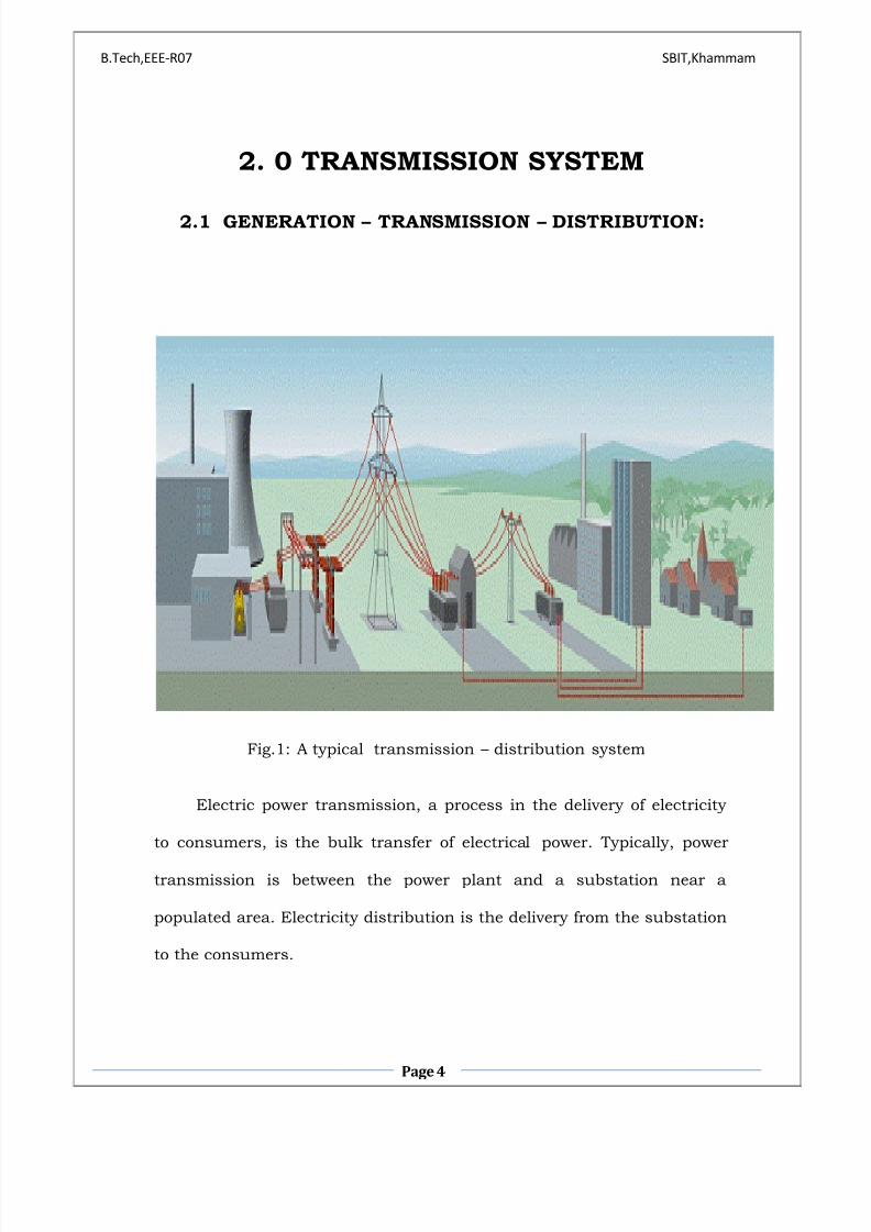
Fig.1: A typical transmission ² distribution system
Electric power transmission, a process in the delivery of electricity
to consumers, is the bulk transfer of electrical power. Typically, power
transmission is between the power plant and a substation near a
populated area. Electricity distribution is the delivery from the substation
to the consumers.

8/8/2019 Copy of Global Positioning Systems
http://slidepdf.com/reader/full/copy-of-global-positioning-systems 5/48
B.Tech,EEE-R07 SBIT,Khammam
Page 5
Electric power transmission allows distant energy sources (such as
hydroelectric power plants) to be connected to consumers in population
centers, and may allow exploitation of low-grade fuel resources that would
otherwise be too costly to transport to ge nerating facilities. Due to the
large amount of power involved, transmission normally takes place at high
voltage (110 kV or above). Electricity is usually transmitted over long
distance through overhead power transmission lines. Underground power
transmission is used only in densely populated areas due to its high cost
of installation and maintenance, and because the high reactive power
produces large charging currents and difficulties in voltage management. A
power transmission system is sometimes referre d to colloquially as a
"grid"; however, for reasons of economy, the network is not a mathematical
grid. Redundant paths and lines are provided so that power can be routed
from any power plant to any load center, through a variety of routes, based
on the economics of the transmission path and the cost of power. Much
analysis is done by transmission companies to determine the maximum
reliable capacity of each line, which, due to system stability
considerations, may be less than the physical or thermal limit o f the line.

8/8/2019 Copy of Global Positioning Systems
http://slidepdf.com/reader/full/copy-of-global-positioning-systems 6/48
B.Tech,EEE-R07 SBIT,Khammam
Page 6
2.2 TRANSMISSION LINE PROTECTION
Transmission lines are a vital part of the electrical distribution
system, as they provide the path to transfer power between generation
and load. Transmission lines operate at voltage levels from 69kV to
765kV, and are ideally tightly interconnected for reliable operation.
Factors like de-regulated market environment, economics, right of-way
clearance and environmental requirements have pushed utilities to
operate transmission lines close to their operating limits. Any fault, if not
detected and isolated quickly will cascade into a system wide disturbance
causing widespread outages for a tightly interconnected system operating
close to its limits. Transmission protection systems are designed to
identify the location of faults and isolate only the faulted section. The key
challenge to the transmission line protection lies in reliably detecting and
isolating faults compromising the security of the system.

8/8/2019 Copy of Global Positioning Systems
http://slidepdf.com/reader/full/copy-of-global-positioning-systems 7/48
8/8/2019 Copy of Global Positioning Systems
http://slidepdf.com/reader/full/copy-of-global-positioning-systems 8/48
B.Tech,EEE-R07 SBIT,Khammam
Page 8
The more detailed factors for transmission line protection directly
address dependability and security for a specific application. The
protection system selected should provide redundancy to limit the impact
of device failure, and backup protection to ensure dependability.
Reclosing may be applied to keep the line in service for temporary faults,
such as lightning strikes. The maximum load current level will impact the
sensitivity of protection functions, and may require adjustment to
protection functions settings during certain operating circumstances.
Single-pole tripping applications impact the performance requirements of
distance elements, differential elements, and communications schemes.
The physical construction of the transmission line is also a factor in
protection system application. The type of conductor, the size of
conductor, and spacing of conductors determines the impedance of the
line, and the physical response to short circuit conditions, as well as line
charging current. In addition, the number of line terminals determines
load and fault current flow, which must be accounted for by the
protection system. Parallel lines also impact relaying, as mutual coupling
influences the ground current measured by protective relays. The
presence of tapped transformers on a line, or reactive compensation
devices such as series capacitor banks or shunt reactors, also influences
the choice of protection system, and the actual protection device settings.

8/8/2019 Copy of Global Positioning Systems
http://slidepdf.com/reader/full/copy-of-global-positioning-systems 9/48
B.Tech,EEE-R07 SBIT,Khammam
Page 9
2.4 WHAT IS TRAVELING WAVE FAULT LOCATION ?
Faults on the power transmission system cause transients that
propagate along the transmission line as waves. Each wave is a composite of
frequencies, ranging from a few kilohertz to several megahertz, having a fast
rising front and a slower decaying tail. Composite waves have a propagation
velocity and characteristic impedance and travel near the speed of light away
from the fault location toward line ends. They continue to travel throughout
the power system until they diminish due to impedance and reflection waves
and a new power system equilibrium is reached. The location of faults is
accomplished by precisely time-tagging wave fronts as they cross a known
point typically in substations at line ends. With wave s time tagged to sub
microsecond resolution of 30 m, fault location accuracy of 300 m can be
obtained. Fault location can then be obtained by multiplying the wave
velocity by the time difference in line ends. This collection and calculation of
time data is usually done at a master station. Master station information
polling time should be fast enough for system operator needs.
Fig.3: Fault location in transmission line
8/8/2019 Copy of Global Positioning Systems
http://slidepdf.com/reader/full/copy-of-global-positioning-systems 10/48
B.Tech,EEE-R07 SBIT,Khammam
Page
10
2.5 BENEFITS OF TRAVELING WAVE FAULT
LOCATION
Early fault locators used pulsed radar. This technique uses
reflected radar energy to determine the fault location. Radar
equipment is typically mobile or located at substations and requires
manual operation. This technique is popular for location of
permanent faults on cable sections when the cable is de -energized.
Impedance-based fault locators are a popular means of transmission
line fault locating. They provide algorithm advances that correct for
fault resistance and load current inaccuracies. Line length acc uracies
of ±5% are typical for single-ended locators and 1-2% for two-ended
locator systems. Traveling wave fault locators are becoming popular
where higher accuracy is important. Long lines, difficult accessibility
lines, high voltage direct current (HVDC), and series-compensated
lines are popular applications. Accuracies of <300 meters have been
achieved on 500 kV transmission lines with this technique. Hewlett-
Packard has developed a GPS-based sub microsecond timing system
that has proven reliable in several utility traveling wave projects. This
low-cost system can also be used as the substation master clock.

8/8/2019 Copy of Global Positioning Systems
http://slidepdf.com/reader/full/copy-of-global-positioning-systems 11/48
B.Tech,EEE-R07 SBIT,Khammam
Page
11
2.6 TRAVELING WAVE FAULT LOCATION THEORY
Traveling wave fault locators make use of the transient signals
generated by the fault. When a line fault occurs, such as an insulator
flashover or fallen conductor, the abrupt change in voltage at the point of
the fault generates a high frequency electromagnetic impulse called the
traveling wave which propagates along the line in both directions away
from the fault point at speeds close to that of light. The fault location is
determined by accurately time-tagging the arrival of the traveling wave at
each end of the line and comparing the time difference to the total
propagation time of the line.
Position is Based on Time
T + 3
Distance between satellite
and receiver = ³3 times the
speed of light´
T
Signal leaves satelliteat time ³T´
Signal is picked up by the
receiver at time ³T + 3´
8/8/2019 Copy of Global Positioning Systems
http://slidepdf.com/reader/full/copy-of-global-positioning-systems 12/48
B.Tech,EEE-R07 SBIT,Khammam
Page
12
Unlike impedance-based fault location systems, the traveling wave
fault locator is unaffected by load conditions, high ground resistance and
most notably, series capacitor banks. This fault locating technique relies
on precisely synchronized clocks at the line terminals which can
accurately time-tag the arrival of the traveling wave. The propagation
velocity of the traveling wave is roughly 300 meters per microsecond
which in turn requires the clocks to be synchronized with respect to each
other by less than one microsecond.
Precisely synchronized clocks are the key element in the
implementation of this fault location technique. The required level of clock
accuracy has only recently been available at reasonable cost with the
introduction of the Global Positioning System.
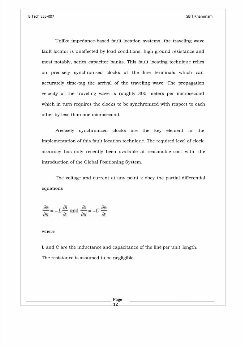
The voltage and current at any point x obey the partial differential
equations
where
L and C are the inductance and capacitance of the line per unit length.
The resistance is assumed to be negligible .
8/8/2019 Copy of Global Positioning Systems
http://slidepdf.com/reader/full/copy-of-global-positioning-systems 13/48
B.Tech,EEE-R07 SBIT,Khammam
Page
13
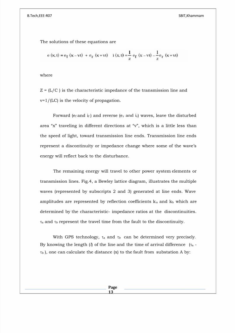
The solutions of these equations are
where
Z = (L/C ) is the characteristic impedance of the transmission line and
v=1/(LC) is the velocity of propagation.
Forward (ef and if ) and reverse (er and ir) waves, leave the disturbed
area ´xµ traveling in different directions at ´vµ, which is a little less than
the speed of light, toward transmission line ends. Transmission line ends
represent a discontinuity or impedance change where some of the wave·s
energy will reflect back to the disturbance.
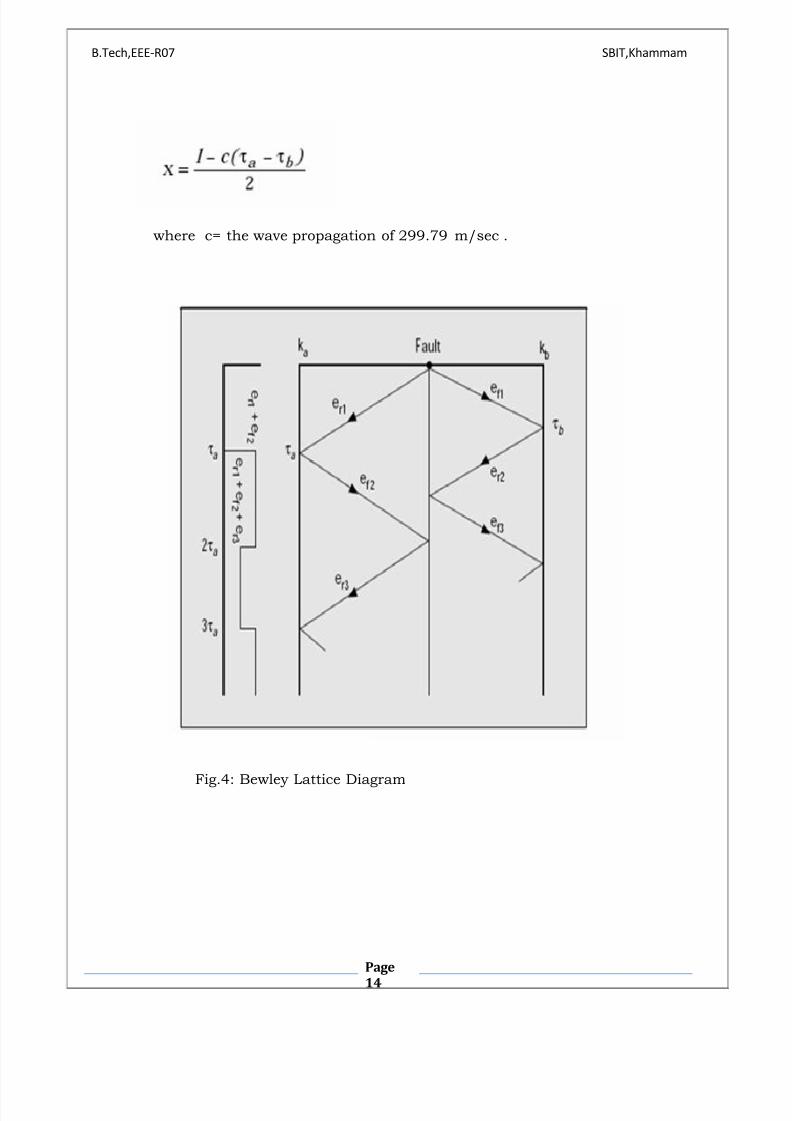
The remaining energy will travel to other power system elements or
transmission lines. Fig.4, a Bewley lattice diagram, illustrates the multiple
waves (represented by subscripts 2 and 3) generated at line ends. Wave
amplitudes are represented by reflection coefficients ka and kb which are
determined by the characteristic- impedance ratios at the discontinuities.
a and b represent the travel time from the fault to the discontinuity.
With GPS technology, a and b can be determined very precisely.
By knowing the length (l ) of the line and the time of arrival difference (a -
b ), one can calculate the distance (x) to the fault from substation A by:
8/8/2019 Copy of Global Positioning Systems
http://slidepdf.com/reader/full/copy-of-global-positioning-systems 14/48
B.Tech,EEE-R07 SBIT,Khammam
Page
14
where c= the wave propagation of 299.79 m/sec .
Fig.4: Bewley Lattice Diagram

8/8/2019 Copy of Global Positioning Systems
http://slidepdf.com/reader/full/copy-of-global-positioning-systems 15/48
B.Tech,EEE-R07 SBIT,Khammam
Page
15
3.0 GLOBAL POSITIONING SYSTEM
3.1 WHAT IS GPS ?
The Global Positioning System (GPS) is a satellite-based navigation
system made up of a network of 24 satellites placed into orbit. GPS was
originally intended for military applications, but in the 1980s, the
government made the system available for civilian use. GPS works in any
weather conditions, anywhere in the world, 24 hours a day. GPS
Technology allows precise determination of location, velocity, direction,
and time. GPS are space-based radio positioning systems that provide
time and three-dimensional position and velocity information to suitably
equipped users anywhere on or near the surface of the earth (and
sometimes off the earth). Concept of satellite navigation was first
conceived after the launch of Sputnik 1 in 1957 when scientists realized
that by measuring the frequency shifts in the small bleeps emanating
from this first space vehicle it was possible to locate a point on the earth's
surface. The NAVSTAR system, operated by the US Department of
Defense, is the first such system widely available to civilian users. The
Russian system, GLONASS, is similar in operation and may prove
complimentary to the NAVSTAR system. Current GPS systems enable
users to determine their three dimensional differential position, velocity
and time. By combining GPS with current and future computer mapping
techniques, we will be better able to identify and manage our natural
8/8/2019 Copy of Global Positioning Systems
http://slidepdf.com/reader/full/copy-of-global-positioning-systems 16/48
B.Tech,EEE-R07 SBIT,Khammam
Page
16
resources. Intelligent fault location systems will provide efficient routes to
our destinations, saving millions of dollars . Businesses with large
amounts of outside plant (railroads, utilities) will be able to manage their
resources more efficiently, reducing consumer costs.
Therefore, GPS systems help to determine the accurate location of
faults on power transmission systems which can save time and resources
for the electric utility industry. Line searches for faults are costly and can
be inconclusive. Accurate information needs can be acquired quickly in a
form most useful to the power system operator communicating to field
personnel.
Fig.5: Constellation of 24 Satellites
8/8/2019 Copy of Global Positioning Systems
http://slidepdf.com/reader/full/copy-of-global-positioning-systems 17/48
B.Tech,EEE-R07 SBIT,Khammam
Page
17
3.2 WHY SHOULD WE GO FOR GPS ?
7777777777777ffbnkjh.077
y To know the exact fault location.
y To avoid repeated power blackouts.
y As time and frequency enable efficient power transmission and
distribution.
y Very accurate fault detectors which even gives 3-D view.
y Is accurate to within 1micro-second at any point on the earth.
y To enable continuous power supply.
y Cheaper way of fault detection.
3.3 HOW DOES GPS WORKS?
GPS satellites circle the earth twice a day in a very precise orbit and
transmit signal information to earth. GPS receivers take this information
and use triangulation to calculate the user's exact location. Essentially,
the GPS receiver compares the time a signal was transmitted by a satellite
with the time it was received. The time difference tells the GPS receiver
how far away the satellite is. Now, with distance measurements from a
few more satellites, the receiver can determine the user's position and
display it on the unit's electronic map. By knowing the distance from
another satellite, the possible positions of the location are narrowed down
to two points (Two intersecting circles have two points in common). A GPS

8/8/2019 Copy of Global Positioning Systems
http://slidepdf.com/reader/full/copy-of-global-positioning-systems 18/48
B.Tech,EEE-R07 SBIT,Khammam
Page
18
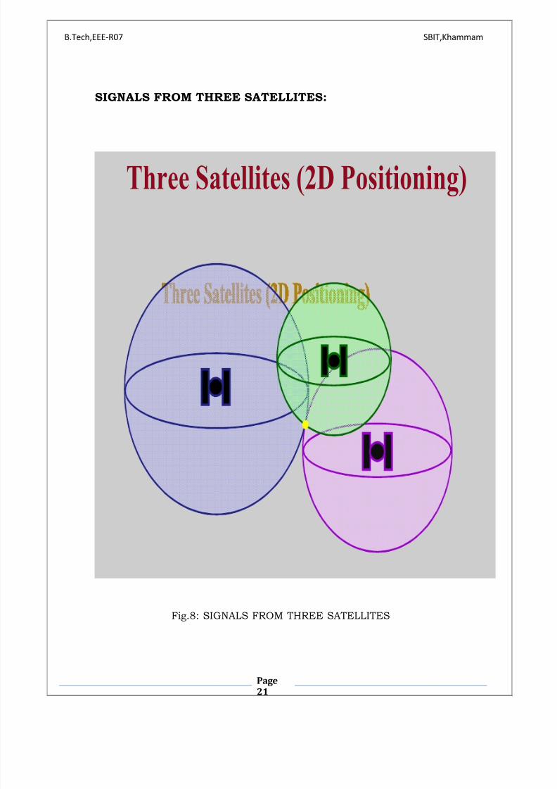
receiver must be locked on to the signal of at least three satellites to
calculate a 2D position (latitude and longitude) and track movement. With
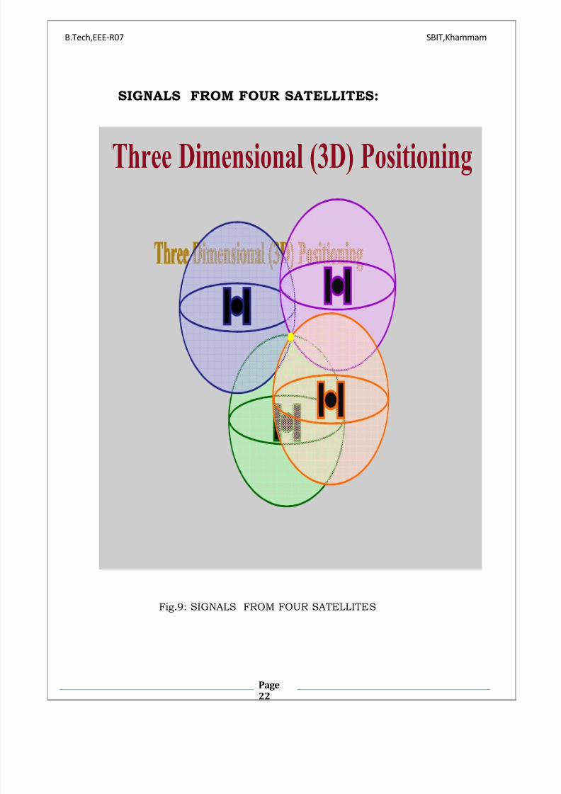
four or more satellites in view, the receiver can determine the user's 3D
position (latitude, longitude and altitude).
Once the user's position has been determined, the GPS unit can
calculate other information, such as speed, bearing, track, trip distance,
distance to destination, sunrise and sunset time and more. Accurate 3-D
measurements require four satellites. To achieve 3-D real time
measurements, the receivers need at least four channels , which are as
shown follows:

8/8/2019 Copy of Global Positioning Systems
http://slidepdf.com/reader/full/copy-of-global-positioning-systems 19/48
B.Tech,EEE-R07 SBIT,Khammam
Page
19
SIGNAL FROM ONE SATELLITE:
Signal From One Satellite
The receiver is
somewhere on
this sphere.
Fig.6: SIGNAL FROM ONE SATELLITE

8/8/2019 Copy of Global Positioning Systems
http://slidepdf.com/reader/full/copy-of-global-positioning-systems 20/48
B.Tech,EEE-R07 SBIT,Khammam
Page
20
SIGNALS FROM TWO SATELLITES:
Signals From Two Satellites
Fig.7: SIGNALS FROM TWO SATELLITES
8/8/2019 Copy of Global Positioning Systems
http://slidepdf.com/reader/full/copy-of-global-positioning-systems 21/48
B.Tech,EEE-R07 SBIT,Khammam
Page
21
SIGNALS FROM THREE SATELLITES:
Three Satellites (2D Positioning)
Fig.8: SIGNALS FROM THREE SATELLITES
8/8/2019 Copy of Global Positioning Systems
http://slidepdf.com/reader/full/copy-of-global-positioning-systems 22/48
B.Tech,EEE-R07 SBIT,Khammam
Page
22
SIGNALS FROM FOUR SATELLITES:
Three Dimensional (3D) Positioning
Fig.9: SIGNALS FROM FOUR SATELLITES
8/8/2019 Copy of Global Positioning Systems
http://slidepdf.com/reader/full/copy-of-global-positioning-systems 23/48
B.Tech,EEE-R07 SBIT,Khammam
Page
23
3.4 THE GPS SATELLITE SYSTEM
The 24 satellites that make up the GPS space segment are orbiting
the earth about 12,000 miles above us. They are constantly moving,
making two complete orbits in less than 24 hours. These satellites are
traveling at speeds of roughly 7,000 miles an hour. GPS satellites are
powered by solar energy. They have backup batteries onboard to keep
them running in the event of a solar eclipse, when there's no solar power.
Small rocket boosters on each satellite keep them flying in the correct
path. Here are some other interesting facts about the GPS satellites (also
called NAVSTAR, the official U.S. Department of Defense name for GPS):
1. The first GPS satellite was launched in 1978.
2. A full constellation of 24 satellites was achieved in 1994.
3. Each satellite is built to last about 10 years. Replacements are
constantly being built and launched into orbit.
4. A GPS satellite weighs approximately 2,000 pounds and is about 17
feet across with the solar panels extended.
5. Transmitter power is only 50 watts or less.

8/8/2019 Copy of Global Positioning Systems
http://slidepdf.com/reader/full/copy-of-global-positioning-systems 24/48
B.Tech,EEE-R07 SBIT,Khammam
Page
24
3.5 WHAT·S THE SIGNAL?
GPS satellites transmit two low power radio signals, designated L1
and L2. GPS uses the L1 frequency of 1575.42 MHz in the UHF band. The
signals travel by line of sight, meaning they will pass through clouds,
glass and plastic but will not go through most solid objects such as
buildings and mountains. A GPS signal contains three different bits of
information ³ a pseudorandom code, ephemeris data and almanac data.
1) PSEUDORANDOM CODE:
The pseudorandom code is simply an I.D. code that identifies which
satellite is transmitting information. We can view this number on your
GPS unit's satellite page, as it identifies which satellites it's receiving.
2) EPHEMERIS DATA:
Ephemeris data tells the GPS receiver where each GPS satellite
should be at any time throughout the day. Each satellite transmits
ephemeris data showing the orbital information for that satellite and for
every other satellite in the system.
8/8/2019 Copy of Global Positioning Systems
http://slidepdf.com/reader/full/copy-of-global-positioning-systems 25/48
B.Tech,EEE-R07 SBIT,Khammam
Page
25
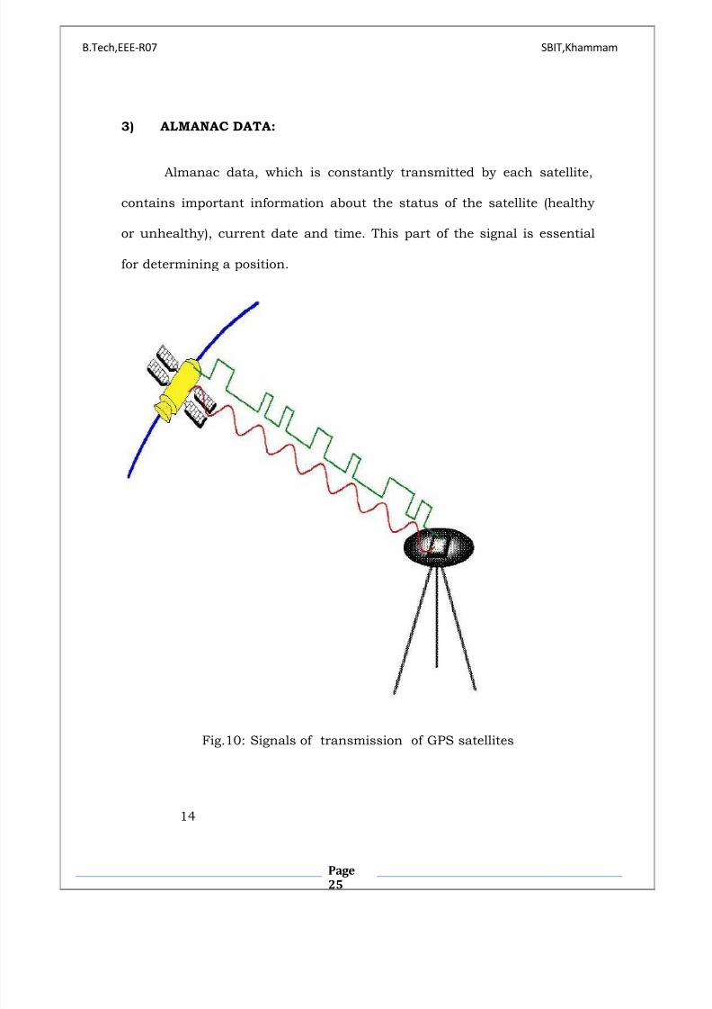
3) ALMANAC DATA:
Almanac data, which is constantly transmitted by each satellite,
contains important information about the status of the satellite (healthy
or unhealthy), current date and time. This part of the signal is essential
for determining a position.
Fig.10: Signals of transmission of GPS satellites
14
8/8/2019 Copy of Global Positioning Systems
http://slidepdf.com/reader/full/copy-of-global-positioning-systems 26/48
B.Tech,EEE-R07 SBIT,Khammam
Page
26
All GPS satellites have several atomic clocks. The signal that is
sent out is a random sequence, each part of which is different from every
other, called pseudo-random code. This random sequence is repeated
continuously. All GPS receivers know this sequence and repeat it
internally. Therefore, satellites and the receivers must be in synch. The
receiver picks up the satellite's transmission and compares the incoming
signal to its own internal signal. By co mparing how much the satellite
signal is lagging, the travel time becomes known.
3.6 GPS SIGNAL CHARACTERISTICS
The satellites transmit on two L-band frequencies: L1 =
1575.42 MHz and L2 = 1227.6 MHz. Three pseudo-random noise (PRN)
ranging codes are in use.
y The coarse/acquisition (C/A) code has a 1.023 MHz chip rate,
a period of 1 millisecond (ms) and is used primarily to acquire the P -code.
y The precision (P) code has a 10.23 MHz rate, a period of 7
days and is the principal ranging code.
y The Y-code is used in place of the P-code whenever the anti-
spoofing (A-S) mode of operation is activated.
The C/A code is available on the L1 frequency and the P -code is
available on both L1 and L2. The various satellites all transmit on the
same frequencies, L1 and L2, but with individual code assignments.

8/8/2019 Copy of Global Positioning Systems
http://slidepdf.com/reader/full/copy-of-global-positioning-systems 27/48
B.Tech,EEE-R07 SBIT,Khammam
Page
27
Due to the spread spectrum characteristic of the signals, the
system provides a large margin of resistance to interference. Each satellite
transmits a message containing its orbital elements, clock behavior,
system time and status messages. In addition, an almanac is also
provided which gives the approximate data for each active satellite. This
allows the user set to find all satellites once the first has been acquired.
3.7 GPS CAPABILITIES
The GPS is a DoD developed, worldwide, satellite-based radio
transmission system that will be the DoD's primary radio transmission
system well into the next century. The constellation consists of 24
operational satellites. The U.S. Air Force Space Command (AFSC) formally
declared the GPS satellite constellation as having met the requirement
for Full Operational Capability (FOC) as of April 27, 1995. Requirements
include 24 operational satellites (Block II/IIA) functioning in their
assigned orbits and successful testing completed for operational
functionality.
Prior to FOC an Initial Operational Capability (IOC) was
declared on December 8, 1993 when 24 GPS satellites (Block-Iand Block-
II/IIA) were operating in their assigned orbits, available for use and
providing the Standard Positioning Service (SPS) levels specified below.
8/8/2019 Copy of Global Positioning Systems
http://slidepdf.com/reader/full/copy-of-global-positioning-systems 28/48
B.Tech,EEE-R07 SBIT,Khammam
Page
28
GPS provides two levels of service: Standard Positioning
Service and the Precise Positioning Service and are as follows:
1) STANDARD POSITIONING SERVICE :
The Standard Positioning Service (SPS) is a positioning and
timing service which will be available to all GPS users on a continuous,
worldwide basis with no direct charge. SPS will be provided on the GPS L1
frequency which contains a coarse acquisition (C/A) code and a data
message. SPS provides a predictable positioning accuracy of 100 meters
(95 percent) horizontally and 156 meters (95 percent) vertically and time
transfer accuracy to UTC within 340 nanoseconds (95 percent).
2) PRECISE POSITIONING SERVICE:
The Precise Positioning Service (PPS) is a highly accurate
positioning, velocity and timing service which will be available on a
continuous, worldwide basis to users authorized by the U.S. P(Y)
code capable user equipment provides a predictable positioning accuracy
of at least 22 meters (95 percent) horizontally and 27.7 meters vertically
and time transfer accuracy to UTC within 200 nanoseconds (95 percent).
PPS will be the data transmitted on the GPS L1 and L2 frequencies. PPS
was designed primarily for U.S. military use. It will be denied to
unauthorized users by the use of cryptography. PPS will be made
available to U.S. and U.S. Federal Government users. Limited, non-

8/8/2019 Copy of Global Positioning Systems
http://slidepdf.com/reader/full/copy-of-global-positioning-systems 29/48
B.Tech,EEE-R07 SBIT,Khammam
Page
29
Federal Government, civil use of PPS, both domestic and foreign, will be
considered upon request and authorized on a case -by-case basis,
provided:
It is in the U.S. national interest to do so.
Specific GPS security requirements can be met by the
applicant.
A reasonable alternative to the use of PPS is not available.
SELECTIVE AVAILABILITY, ANTI-SPOOFING:
Selective Availability (SA), the denial of full accuracy, is
accomplished by manipulating navigation message orbit data (epsilon)
and/or satellite clock frequency (dither).
Anti-spoofing (A-S) guards against fake transmissions of
satellite data by encrypting the P-code to form the Y-code.
SA will be implemented on Block II at the SPS levels, as soon as
each Block II satellite is operational.
HAPTER-14CCCCC
3.8 HOW ACCURATE IS GPS?
Today's GPS receivers are extremely accurate, due to their parallel
multi-channel design. 12 parallel channel receivers are quick to lock onto
satellites when first turned on and they maintain strong locks, even in
dense foliage or urban settings with tall buildings. Certain atmospheric
factors and other sources of error can affect the accuracy of GPS
8/8/2019 Copy of Global Positioning Systems
http://slidepdf.com/reader/full/copy-of-global-positioning-systems 30/48
B.Tech,EEE-R07 SBIT,Khammam
Page
30
receivers. GPS receivers are accurate to within 15 meters on average.
Newer GPS receivers with WAAS (Wide Area Augmentation System)
capability can improve accuracy to less than three meters on average. No
additional equipment or fees are required to take advantage of WAAS.
Users can also get better accuracy with Differential GPS (DGPS), which
corrects GPS signals to within an average of three to five meters. The U.S.
Coast Guard operates the most common DGPS correction service. This
system consists of a network of towers that receive GPS signals and
transmit a corrected signal by beacon transmitters. In order to get the
corrected signal, users must have a differential beacon receiver and
beacon antenna in addition to their GPS.
8/8/2019 Copy of Global Positioning Systems
http://slidepdf.com/reader/full/copy-of-global-positioning-systems 31/48
B.Tech,EEE-R07 SBIT,Khammam
Page
31
4.0 FAULT LOCATION METHODS
4.1 TIME DOMAIN REFLECTOMETERS
Early fault locators were based on pulse radar techniques. These
devices known as time domain reflectometers (TDRs), are commonly used
for locating faults in buried cables where visual inspection is not possible
without excavation. This technique makes use of a "probe" pulse that is
launched into one end of the cable and relies on the pulse being reflected
back to the source due to an electrical discontinuity a t the faulted
location. The fault location is determined by measuring the time delay
from launching the pulse and receiving its reflection. There is, however,
little interest in applying this method to overhead transmission lines.
Several factors make this technique impracticable.
Unlike cables which are physically and electrically uniform
throughout its length, overhead lines have inherent discontinuities such
as tower structures, conductor variations, etc. that cause unwanted
secondary reflections which interfere with detecting the reflected "probe"
pulse.
The faulted line must be taken out of service to conduct testing and
special precautions must be taken to ensure mutual inductance effects
from healthy adjacent lines and nearby energized equipment does not
pose a safety hazard.

8/8/2019 Copy of Global Positioning Systems
http://slidepdf.com/reader/full/copy-of-global-positioning-systems 32/48
B.Tech,EEE-R07 SBIT,Khammam
Page
32
The fault must be permanent (e.g.. solid short or open
conductors) to ensure a strong reflected signal. Difficult to find faults
such as ice build-up, galloping conductors, etc., conveniently disappear
by the time the fault location equipment can be mobilized and put into
service.
Time domain reflectors used on transmission lines for many years
before largely abandoning this technique due to its complexity and small
gains.
4.2 IMPEDENCE-BASED FAULT LOCATON
METHODS
The largest area of development on fault location methods are those
based on the measurement of system frequency (6OHz) signals. These
methods make use of information from the transmission lines that are
already available for protective relaying purposes (i.e . line voltage and
current). In the most general sense, these techniques analyze the
impedance characteristics of the line to determine the fault location.
Early fault locators were based on the reactance method where fault
location is determined by measuring the ratio of the reactance of the
faulted line at the source end to the unfaulted line reactance, the
assumption being that the fault impedance is purely resistive.
8/8/2019 Copy of Global Positioning Systems
http://slidepdf.com/reader/full/copy-of-global-positioning-systems 33/48
B.Tech,EEE-R07 SBIT,Khammam
Page
33
More complex algorithms make use of pre- and post-fault
conditions to reduce the effects of sources (except for the virtual source at
the fault) and loads. The development of digital fault recorders and digital
protective relays has made it possible to implement better and
computationally more complex algorithms. Many of these methods involve
simultaneous solutions of non-linear equations which can easily be
implemented using iterative techniques. On the 500 kV system where
accurate fault location is of much greater importance, the use of series
compensation precludes the use of these relays for fault location. In long
transmission lines, reactive compensation in the form of a series capacitor
is typically inserted at the midpoint of the line to compensate for the line
inductance and increase the load carrying capacity of the line.
A fault on a series compensated line produces transient frequencies
below the power system frequency that are the result of the natural
resonance of the series capacitance and system inductance. The frequency
of these oscillations depends largely on the sou rce impedance and can lie
close to the power system frequency. These transient frequencies can
produce spurious outputs, causing inaccurate fault location.
8/8/2019 Copy of Global Positioning Systems
http://slidepdf.com/reader/full/copy-of-global-positioning-systems 34/48
B.Tech,EEE-R07 SBIT,Khammam
Page
34
4.3 TRAVELLING WAVE FAULT LOCATION
Traveling wave fault locators make use of the transient signals
generated by the fault. When a line fault occurs, such as an insulator
flashover or fallen conductor, the abrupt change in voltage at the point of
the fault generates a high frequency electromagnetic impulse called the
traveling wave which propagates along the line in both directions away
from the fault point at speeds close to that of light. The fault location is
determined by accurately time-tagging the arrival of the traveling wave at
each end of the line and comparing the time difference to the total
propagation time of the line.
Unlike impedance-based fault location systems, the traveling wave
fault locator is unaffected by load conditions, high ground resistance and
most notably, series capacitor banks. This fault locating technique relies
on precisely synchronized clocks at the line terminals which can
accurately time-tag the arrival of the traveling wave.
The propagation velocity of the traveling wave is roughly 300 meters
per microsecond which in turn requires the clocks to be synchronized with
respect to each other by less than one microsecond.

8/8/2019 Copy of Global Positioning Systems
http://slidepdf.com/reader/full/copy-of-global-positioning-systems 35/48
B.Tech,EEE-R07 SBIT,Khammam
Page
35
Precisely synchronized clocks is the key element in the
implementation of this fault location technique. The required level of clock
accuracy has only recently been available at reasonable cost with the
introduction of the Global Positioning System. CBasic fault locator principle
figure is as follows:
Fig.11: Travelling wave fault location

8/8/2019 Copy of Global Positioning Systems
http://slidepdf.com/reader/full/copy-of-global-positioning-systems 36/48
B.Tech,EEE-R07 SBIT,Khammam
Page
36
5.0 IMPLEMENTATION AND TESTING
Evaluation of the fault locator involved the installation of GPS timing
receivers at four 500 kV substations, as in Fig.12. A especially developed
Fault Transient Interface Unit (FTIU) connects to the transmission lines
and discriminates for a valid traveling wave. The FTIU produces a TTL-
level trigger pulse that is coincident with the leading edge of the traveling
wave.
A time-tagging input function was provided under special request to
the GPS receiver manufacturer. This input accepts the TTL level logic
pulse from the FTIU and time tags the arrival of the fault-generated
traveling wave. The time tag function is accurate to within 300
nanoseconds of UTC - well within the overall performance requirement of
timing to within 1microsecond.
The fault locator tested by placing B-phase to ground faults on line
using a high speed ground switch. Twelve faults were applied to the line
and the fault locator successfully located all twelve faults to well within
the design goal of plus or minus one tower span (300 meters) accuracy.
The results are summarized in Table 1.
8/8/2019 Copy of Global Positioning Systems
http://slidepdf.com/reader/full/copy-of-global-positioning-systems 37/48
B.Tech,EEE-R07 SBIT,Khammam
Page
37
5.1 ADDITIONAL SOURCES OF VERIFICATION :
The fault locator responds to any traveling wave impulse with
sufficient energy in the 35 kHz to 350 kHz range. These impulses are not
limited to those generated by actual transmission line faults. Routine
switching of substation equipment also produces similar fast rise time
impulses which are also detected and time tagged by the fault locator.
These station-generated traveling waves provide an opportunity to test
(and calibrate) the fault locator by comparing the measured results
against the total propagation time of the line a known quantity. Traveling
waves generated by routine operation of 500 kV equipment at NIC, KLY
and ING substations over a period of one year indicated repeatability of
fault location measurements to within the one microsecond or 300 meter
performance accuracy goal. The values are summarized in Table 2.
5.2 EFFECTS OF SERIES CAPACITOR BANKS :
A prime consideration leading to the development a traveling wave
fault locator was the use of series capacitor banks has made it very
difficult if not impossible for the system frequency (60Hz) or impedance-
based fault location techniques to operate properly i.e. fault location using
digital relays and digital fault recorders. The high frequency fault-

8/8/2019 Copy of Global Positioning Systems
http://slidepdf.com/reader/full/copy-of-global-positioning-systems 38/48
B.Tech,EEE-R07 SBIT,Khammam
Page
38
generated traveling waves on the other hand, are not affected by series
capacitor banks. There are series capacitor banks installed on lines .
Testing using traveling waves generated by reactor switching at NIC and
KLY showed the capacitor banks did not have any noticeable effects on
the propagation of the traveling waves.
5.3 DISTORTION AND ATTENUATION OF
TRAVELING WAVES
The accuracy of fault location depends on the ability to accurately
time tagging the arrival of the traveling wave at each line terminal. The
traveling wave once generated, is subject to attenuation and distortion as
it propagates along the transmission line. Attenuation occurs due to
resistive and radiated losses. Distortion of the waveform occurs due to a
variety of factors including bandwidth limitations of the transmission line,
dispersion from different propagation constants of phase -to-phase and
phase-to-ground components, etc. These effects combine to degrade the
quality of the "leading edge" of the traveling wave at large distances from
the fault inception point. The accuracy of time tagging the traveling wave
diminishes for the substations far away from the fault. Experience with
the evaluation system has shown that the traveling wave is relatively
"undistorted" for distances less than 350 km. To effectively reduce the
effects of attenuation and distortion requires traveling wave detector
installations spaced at regular intervals.

8/8/2019 Copy of Global Positioning Systems
http://slidepdf.com/reader/full/copy-of-global-positioning-systems 39/48
B.Tech,EEE-R07 SBIT,Khammam
Page
39
CASE STUDY:
For B.C. Hydro, this translates to installing fault location equipment at
fourteen out of nineteen 500 kV substations.
Fault Locator System Test:
Calculated cumulative arc length from NIC substation to the fault =
131,694.5 meters.
Table 1: Fault locator output and its difference from estimated value
TestFault Locator Output
(meters)
Difference from Estimated
Value (meters)
1 131725 30
2 131819 124
3 131721 26
4 131803 108
5 131800 105
6 131834 139
7 131730 35
8 131697 2
9 131829 134
10 131806 111
11 131810 115
12 131814 119

8/8/2019 Copy of Global Positioning Systems
http://slidepdf.com/reader/full/copy-of-global-positioning-systems 40/48
B.Tech,EEE-R07 SBIT,Khammam
Page
40
Table 2: Fault Locator Response to Traveling Waves Generated by the
Routine Switching of Substation Equipment:
Line estimated T p (sec) Measured T p (sec)
501 499
66 67
850 851
900 896
901 901
The distance to the fault from the line terminals is given by:
Where Vp is the velocity of propagation for the line and

8/8/2019 Copy of Global Positioning Systems
http://slidepdf.com/reader/full/copy-of-global-positioning-systems 41/48
B.Tech,EEE-R07 SBIT,Khammam
Page
41
Denotes stations with travelling wave-detector installations
Fig.12: Fault Locator Installations and Testing

8/8/2019 Copy of Global Positioning Systems
http://slidepdf.com/reader/full/copy-of-global-positioning-systems 42/48
B.Tech,EEE-R07 SBIT,Khammam
Page
42
6.0 GPS SYNCHRONISATION SYSTEM
GPS time Synchronization: Power system reliability starts with
precision timing.
Precision timing is required for monitoring and control of
electrical power networks where power system reliability is important.
Circuit breaker control schemes require precise timing to ensure
proper operation, and Sequence of Events Recording systems report
events with one-millisecond precision to aid diagnostics and
troubleshooting. Typical ´critical powerµ applications include electric
utility networks, data centres, hospitals, water treatment plants,
refineries, and other process industries.

8/8/2019 Copy of Global Positioning Systems
http://slidepdf.com/reader/full/copy-of-global-positioning-systems 43/48
B.Tech,EEE-R07 SBIT,Khammam
Page
43
Global Positioning Systems can be used to provide a precise
time reference for power system devices in an electrical network,
ensuring time synchronization even across great distances. A generic
GPS system architecture is shown below:
Generic GPS Synchronisation Architecture for Power Systems
A GPS antenna receives a time signal from the system of
satellites orbiting the Earth. A GPS receiver accepts raw time data
from the antenna and converts it to one or more time protocols.
Each power system device accepts a sync pulse, usually via a
8/8/2019 Copy of Global Positioning Systems
http://slidepdf.com/reader/full/copy-of-global-positioning-systems 44/48
B.Tech,EEE-R07 SBIT,Khammam
Page
44
dedicated, high-speed digital input. The device then sets its internal
clock by decoding the supported time protocol.
Power companies and utilities have fundamental requirements for
time and frequency to enable efficient power transmission and
distribution. Repeated power blackouts have demonstrated to power
companies the need for improved time synchronization throughout the
power grid. Analyses of these blackouts have led many companies to place
GPS-based time synchronization devices in power plants and substations.
By analyzing the precise timing of an electrical anomaly as it propagates
through a grid, engineers can trace back the exact location of a power line
break.
8/8/2019 Copy of Global Positioning Systems
http://slidepdf.com/reader/full/copy-of-global-positioning-systems 45/48
B
¡
ec ¢
£
¤ ¤ ¤ - ¥ 07 SB ¦
¡
£
§ ¢ ¨ © © ¨ ©
P
45
S/S A S/S B
GRL100 GRL100
GPS communication GPS receiver System
Sampling Sampling receiver OSC OSC
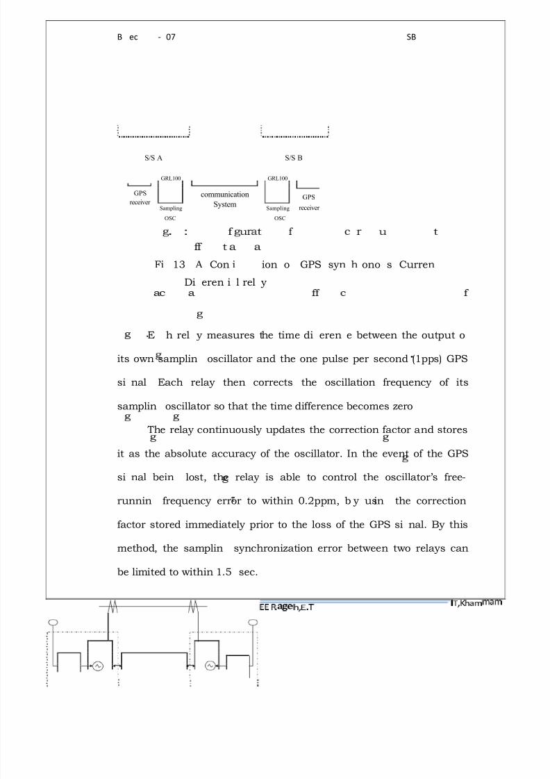
Fi
13 A Con i
ion o GPS syn! h ono s Curren
Di eren i l rel y
E !
h rel y measures the time di eren! e between the output o
its own samplin oscillator and the one pulse per second (1pps) GPS
si nal
Each relay then corrects the oscillation frequency of its
samplin
oscillator so that the time difference becomes zero
The relay continuousl y updates the correction factor and stores
it as the absolute accuracy of the oscillator. In the event of the GPS
si nal bein lost, the relay is able to control the oscillator·s free-
runnin frequency error to within 0.2ppm, b y usin the correction
factor stored immediatel y prior to the loss of the GPS si nal. By this
method, the samplin synchronization error between two relays can
be limited to within 1.5" sec.

8/8/2019 Copy of Global Positioning Systems
http://slidepdf.com/reader/full/copy-of-global-positioning-systems 46/48
B.Tech,EEE-R07 SBIT,Khammam
Page
46
Fig.14 shows the GPS standard time signal that is provided to
the relay from the GPS receiver. The standard time data is encoded so
that any failure or corruption of the standard time signal can be
detected by the relays, thus ensuring that sampling synchronization
control is not adversely affected.
St# $ d# % d &
' ' ( (
i) $ # l
Ti0 1 d#
t#
&
( 1 2 3 $
d
Fig.14: GPS standard time signal

8/8/2019 Copy of Global Positioning Systems
http://slidepdf.com/reader/full/copy-of-global-positioning-systems 47/48
B.Tech,EEE-R07 SBIT,Khammam
Page
47
CHAPTER-1CHAPTER-204
7.0 CONCLUSION
Thus the use of GPS in protection of transmission systems is
beneficial with respect to
Value regarding programmatic goals: more reliable monitoring using
GPS related technologies.
Technical merit: new fault location algorithm based on new input
data.
Overall performance: on time, with all goals met so far.
8/8/2019 Copy of Global Positioning Systems
http://slidepdf.com/reader/full/copy-of-global-positioning-systems 48/48
B.Tech,EEE-R07 SBIT,Khammam
8.0 REFERENCES :
1. Transmission lines and networks ² Umesh Sinha
2. Communication & Control in electric power systems-applications-
M. Shahidehpeur and Yaouyu Wang, google books
3. Global Positioning Systems- Pratap Mishra and Per Enge
4. Wikipedia of transmission line protection methods and Global
Positioning Systems
5. Website of National Institute of standards &Technology (NIST) time
and frequency division.