Embed Size (px)
Citation preview
1
N ki F d lN ki F d l1 Networking FundamentalsNetworking Fundamentals1
Copyleft © 2005, Binnur Kurt
s1
Objectives
►Define basic networking terms►Describe some commonly used network applications►Describe the main purposes and functions of computer
rkin
g Fu
ndam
enta
l ►Describe the main purposes and functions of computer networking
►Describe the history and purposes of the OSI reference model
9
Net
wor
BTE550 – Internet and Intranet Applications
2
s1
Objectives (Cont.)
►Discuss the functions of each of the seven layers of the OSI reference model and provide examples of each
►Describe the basic process of communication between the
rkin
g Fu
ndam
enta
l ►Describe the basic process of communication between thelayers of the OSI reference model
►Describe the functions of the TCP/protocol stack and provide examples of each layer’s function
►Compare the TCP/IP protocol stack to the OSI reference model
10
Net
wor
BTE550 – Internet and Intranet Applications
s1
Basic Networking Terminology►NIC►Media►Protocol
rkin
g Fu
ndam
enta
l ►Protocol►NOS►Connectivity devices►LAN►MAN►WAN
11
Net
wor
BTE550 – Internet and Intranet Applications
►WAN►Physical topology►Logical topology
3
s1
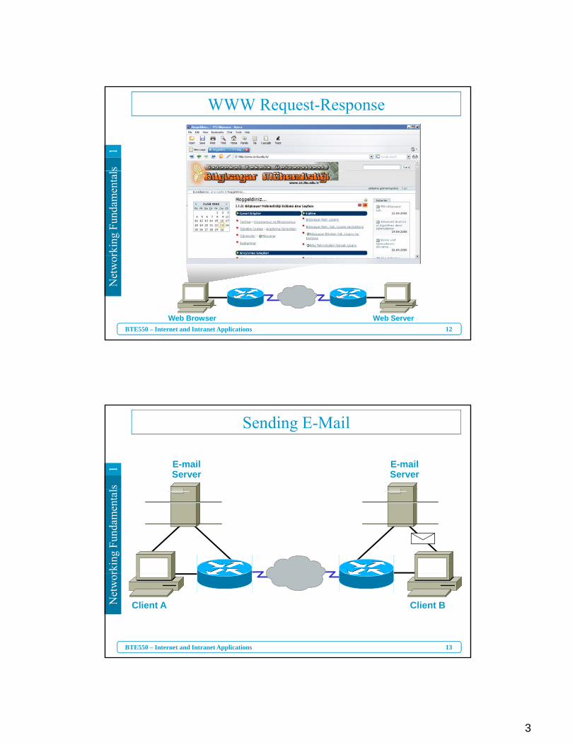
WWW Request-Responserk
ing
Fund
amen
tal
12
Net
wor
BTE550 – Internet and Intranet ApplicationsWeb Browser Web Server
s1
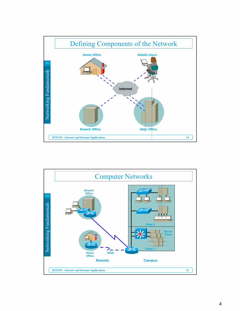
Sending E-Mail
E-mailServer
E-mailServer
rkin
g Fu
ndam
enta
l
13
Net
wor
BTE550 – Internet and Intranet Applications
Client A Client B
4
s1
Defining Components of the NetworkHome Office Mobile Users
rkin
g Fu
ndam
enta
l
Internet
14
Net
wor
BTE550 – Internet and Intranet Applications
Branch Office Main Office
s1
Computer Networks
BranchOffice
rkin
g Fu
ndam
enta
l
Floor 2
ServerFarm
15
Net
wor
BTE550 – Internet and Intranet Applications
HomeOffice
ISDN
Remote Campus
Floor 1
5
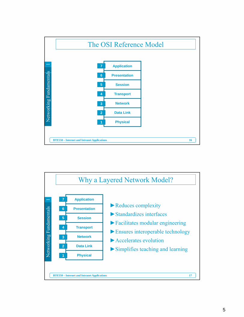
s1 Application
The OSI Reference Model
7
rkin
g Fu
ndam
enta
l Presentation
Session
Transport
Network
6
5
4
3
16
Net
wor
BTE550 – Internet and Intranet Applications
Data Link
Physical
2
1
s1
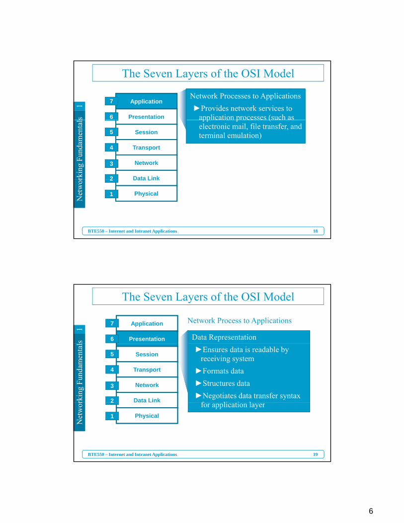
Why a Layered Network Model?
►Reduces complexityApplication
Presentation
7
6
rkin
g Fu
ndam
enta
l p y►Standardizes interfaces►Facilitates modular engineering►Ensures interoperable technology►Accelerates evolution
Presentation
Session
Transport
Network
6
5
4
3
17
Net
wor
BTE550 – Internet and Intranet Applications
►Simplifies teaching and learningData Link
Physical
2
1
6
s1
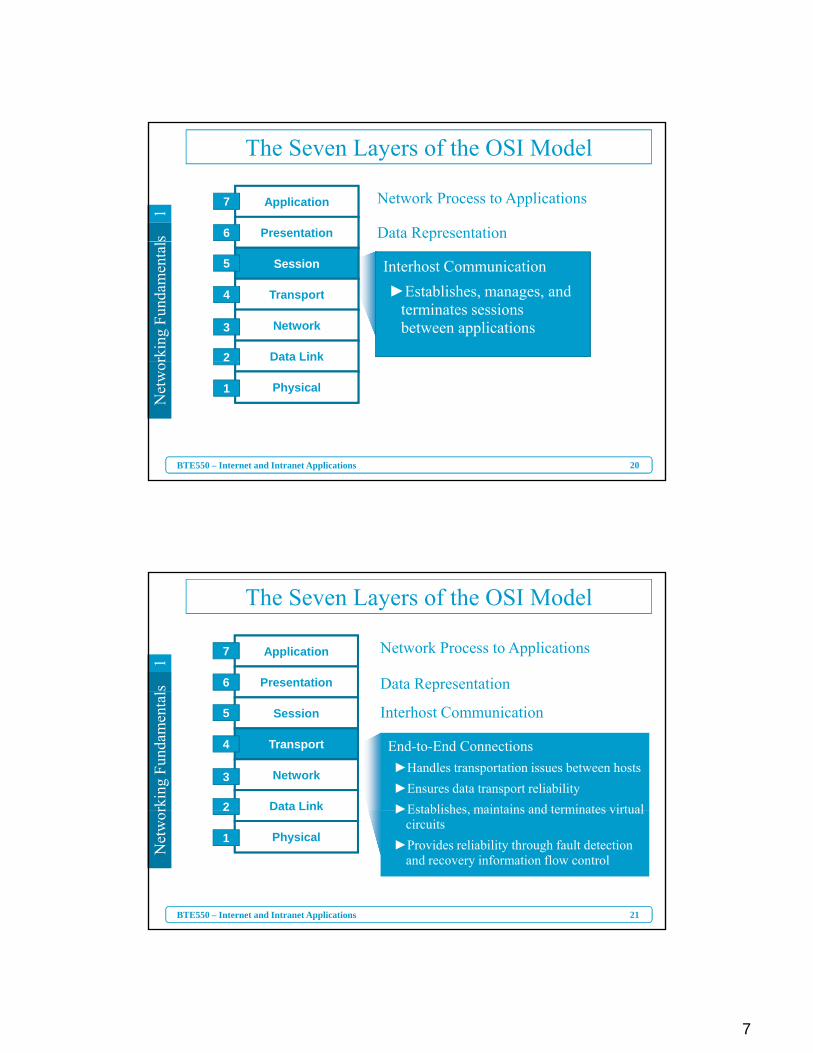
The Seven Layers of the OSI Model
Network Processes to Applications►Provides network services to
application processes (such as
Application
Presentation
7
6
rkin
g Fu
ndam
enta
l pp c o p ocesses (suc selectronic mail, file transfer, and terminal emulation)Session
Transport
Network
Data Link
5
4
3
2
18
Net
wor
BTE550 – Internet and Intranet Applications
Data Link
Physical
2
1
s1
The Seven Layers of the OSI Model
Data Representation
Network Process to ApplicationsApplication
Presentation
7
6
rkin
g Fu
ndam
enta
l
►Ensures data is readable byreceiving system
►Formats data►Structures data►Negotiates data transfer syntax
f li ti l
Session
Transport
Network
Data Link
5
4
3
2
19
Net
wor
BTE550 – Internet and Intranet Applications
for application layerPhysical
2
1
7
s1
The Seven Layers of the OSI Model
Network Process to Applications
Data Representation
Application
Presentation
7
6
rkin
g Fu
ndam
enta
l
Interhost Communication►Establishes, manages, and
terminates sessions between applications
Session
Transport
Network
Data Link
5
4
3
2
20
Net
wor
BTE550 – Internet and Intranet Applications
Physical
2
1
s1
The Seven Layers of the OSI Model
Network Process to Applications
Data Representation
Application
Presentation
7
6
rkin
g Fu
ndam
enta
l
End-to-End Connections►Handles transportation issues between hosts►Ensures data transport reliability►Establishes maintains and terminates virtual
Interhost Communication
p
Session
Transport
Network
Data Link
5
4
3
2
21
Net
wor
BTE550 – Internet and Intranet Applications
►Establishes, maintains and terminates virtual circuits
►Provides reliability through fault detection and recovery information flow control
Physical
2
1

8
s1
The Seven Layers of the OSI Model
Network Process to Applications
Data Representation
Application
Presentation
7
6
rkin
g Fu
ndam
enta
l
Data Delivery►Provides connectivity and path
selection between two host
End-to-End Connections
Interhost CommunicationSession
Transport
Network
Data Link
5
4
3
2
22
Net
wor
BTE550 – Internet and Intranet Applications
selection between two host systems
►Routes data packets►Selects best path to deliver data
Physical
2
1
s1
The Seven Layers of the OSI Model
Network Process to Applications
Data Representation
Application
Presentation
7
6
rkin
g Fu
ndam
enta
l
Access to Media
End-to-End Connections
Data Delivery
Interhost CommunicationSession
Transport
Network
Data Link
5
4
3
2
23
Net
wor
BTE550 – Internet and Intranet Applications
Access to Media►Defines how data is formatted for
transmission and how access to the network is controlled
Physical1
9
s1
The Seven Layers of the OSI Model
Network Process to Applications
Data Representation
Application
Presentation
7
6
rkin
g Fu
ndam
enta
l
End-to-End Connections
Data Delivery
Access to Media
Interhost CommunicationSession
Transport
Network
Data Link
5
4
3
2
24
Net
wor
BTE550 – Internet and Intranet Applications
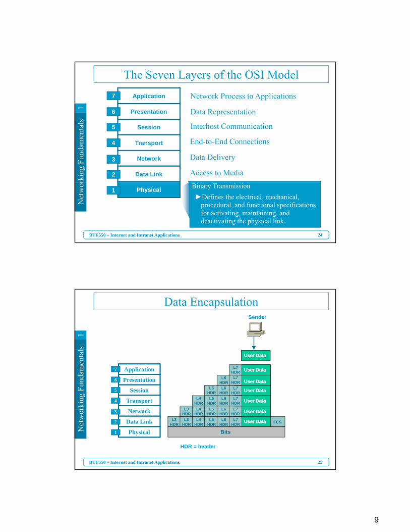
Binary Transmission►Defines the electrical, mechanical,
procedural, and functional specifications for activating, maintaining, anddeactivating the physical link.
Physical1
s1
Data EncapsulationSender
rkin
g Fu
ndam
enta
l
User DataUser Data
User DataUser Data
User DataUser Data
User DataUser Data
User DataUser DataL7
L7HDR
L7HDR
L7HDR
L7HDR
L6
L6HDR
L6HDR
L6HDR
L5
L5HDR
L5HDR
L4
L4HDR
L3
Application
Presentation
Session
Transport
N t k
7
6
5
4
25
Net
wor
BTE550 – Internet and Intranet Applications
HDR = header
Bits
User DataUser Data
User DataUser DataL2
HDRL3
HDRL4
HDRL5
HDRL6
HDRL7
HDR FCS
L7HDR
L6HDR
L5HDR
L4HDR
L3HDRNetwork
Data Link
Physical
3
2
1
10
s1
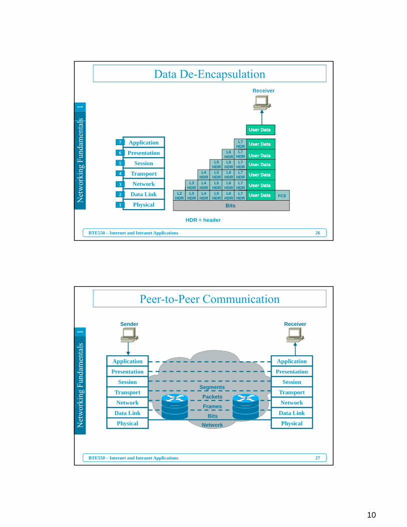
Data De-EncapsulationReceiver
rkin
g Fu
ndam
enta
l
Application
Presentation
Session
Transport
7
6
5
4
User DataUser Data
User DataUser Data
User DataUser Data
User DataUser Data
User DataUser DataL7HDR
L7HDR
L7HDR
L7HDR
L6HDR
L6HDR
L6HDR
L5HDR
L5HDR
L4HDR
26
Net
wor
BTE550 – Internet and Intranet Applications
Network
Data Link
Physical
3
2
1
HDR = header
Bits
User DataUser Data
User DataUser DataL2
HDRL3
HDRL4
HDRL5
HDRL6
HDRL7
HDR FCS
L7HDR
L6HDR
L5HDR
L4HDR
L3HDR
s1
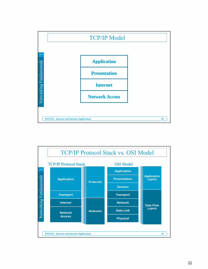
Peer-to-Peer Communication
ReceiverSender
rkin
g Fu
ndam
enta
l
Frames
Packets
Segments
Application
Presentation
Session
Transport
Network
Application
Presentation
Session
Transport
Network
27
Net
wor
BTE550 – Internet and Intranet Applications
NetworkBits
FramesData Link
Physical
Data Link
Physical
11
s1
ApplicationApplication
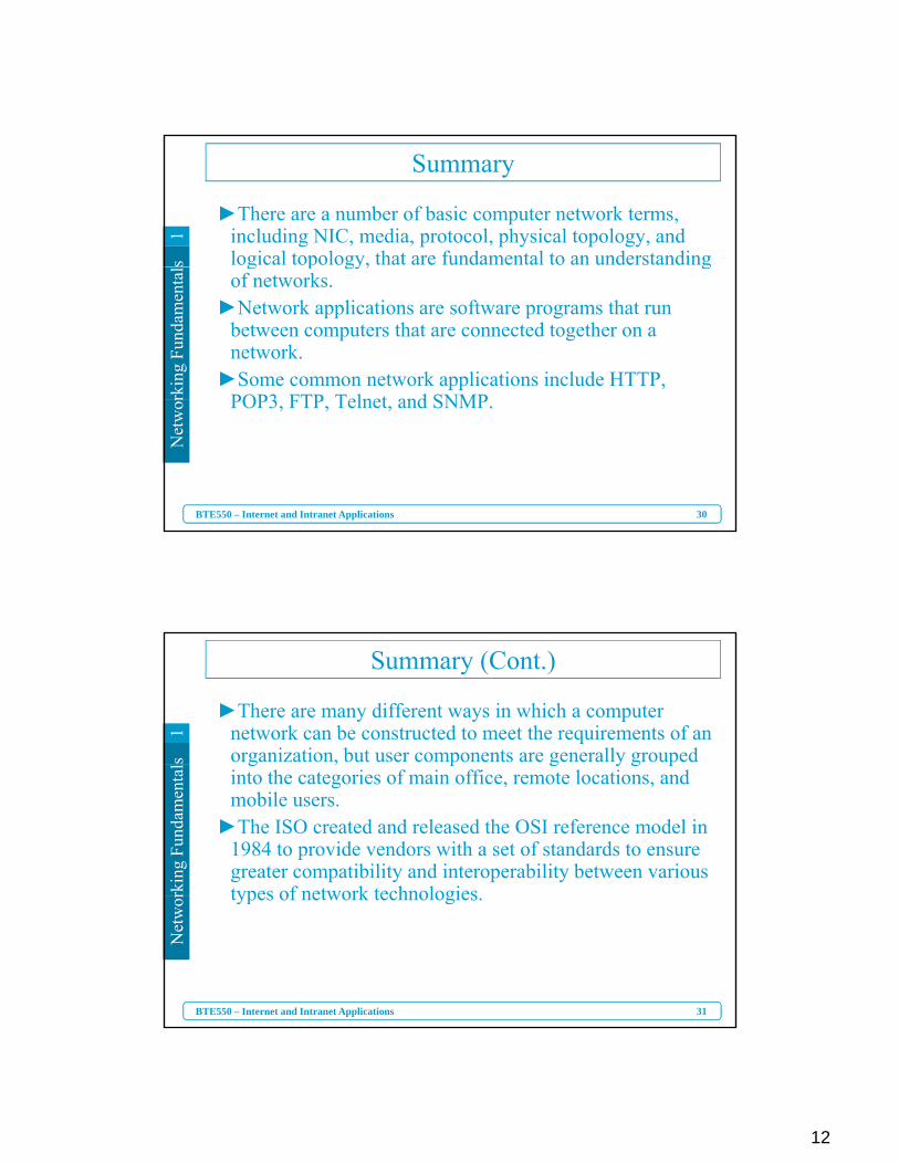
TCP/IP Modelrk
ing
Fund
amen
tal ApplicationApplication
PresentationPresentation
InternetInternet
28
Net
wor
BTE550 – Internet and Intranet Applications
Network AccessNetwork Access
s1
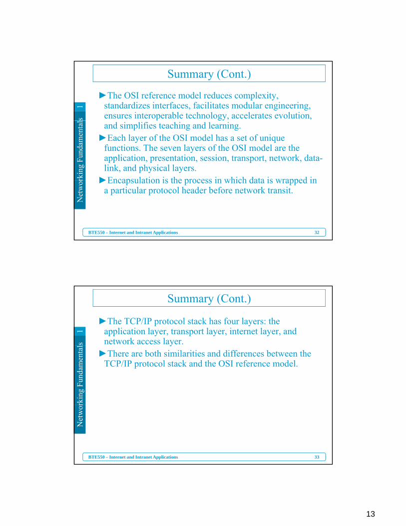
TCP/IP Protocol Stack vs. OSI Model
Application
TCP/IP Protocol StackTCP/IP Protocol Stack OSI ModelOSI Model
Application
rkin
g Fu
ndam
enta
l
Presentation
Session
Transport
Network
Application
Transport
Internet
Protocols
Data Flow
ApplicationLayers
29
Net
wor
BTE550 – Internet and Intranet Applications
Data Link
Physical
NetworkAccess
NetworksLayers
12
s1
Summary
►There are a number of basic computer network terms, including NIC, media, protocol, physical topology, and logical topology, that are fundamental to an understanding
rkin
g Fu
ndam
enta
l g p gy, gof networks.
►Network applications are software programs that run between computers that are connected together on a network.
►Some common network applications include HTTP, POP3 FTP Telnet and SNMP
30
Net
wor
BTE550 – Internet and Intranet Applications
POP3, FTP, Telnet, and SNMP.
s1
Summary (Cont.)
►There are many different ways in which a computer network can be constructed to meet the requirements of an organization, but user components are generally grouped
rkin
g Fu
ndam
enta
l g , p g y g pinto the categories of main office, remote locations, and mobile users.
►The ISO created and released the OSI reference model in 1984 to provide vendors with a set of standards to ensure greater compatibility and interoperability between various types of network technologies
31
Net
wor
BTE550 – Internet and Intranet Applications
types of network technologies.
13
s1
Summary (Cont.)
►The OSI reference model reduces complexity, standardizes interfaces, facilitates modular engineering, ensures interoperable technology, accelerates evolution,
rkin
g Fu
ndam
enta
l and simplifies teaching and learning.►Each layer of the OSI model has a set of unique
functions. The seven layers of the OSI model are the application, presentation, session, transport, network, data-link, and physical layers.
►Encapsulation is the process in which data is wrapped in
32
Net
wor
BTE550 – Internet and Intranet Applications
►Encapsulation is the process in which data is wrapped in a particular protocol header before network transit.
s1
Summary (Cont.)
►The TCP/IP protocol stack has four layers: the application layer, transport layer, internet layer, and network access layer.
rkin
g Fu
ndam
enta
l y►There are both similarities and differences between the
TCP/IP protocol stack and the OSI reference model.
33
Net
wor
BTE550 – Internet and Intranet Applications
14
s1
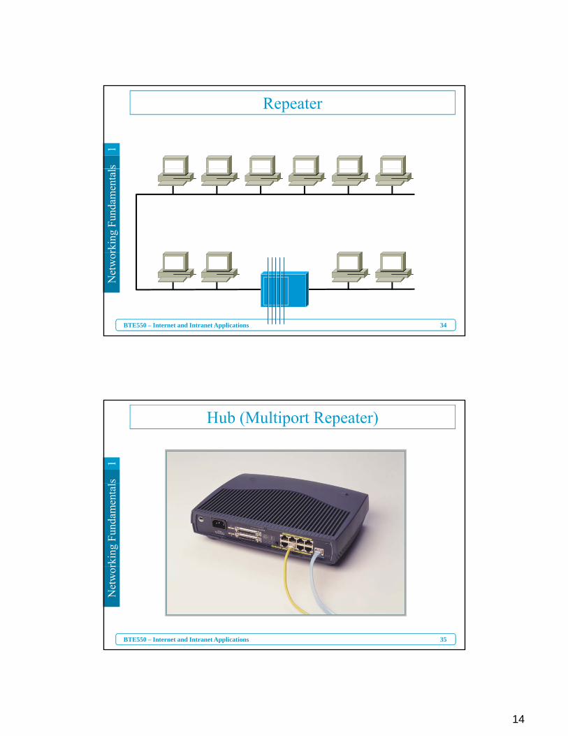
Repeaterrk
ing
Fund
amen
tal
34
Net
wor
BTE550 – Internet and Intranet Applications
s1
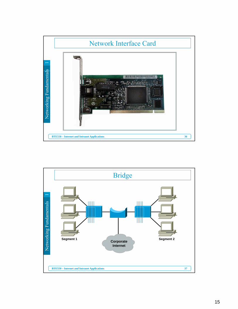
Hub (Multiport Repeater)
rkin
g Fu
ndam
enta
l
35
Net
wor
BTE550 – Internet and Intranet Applications
15
s1
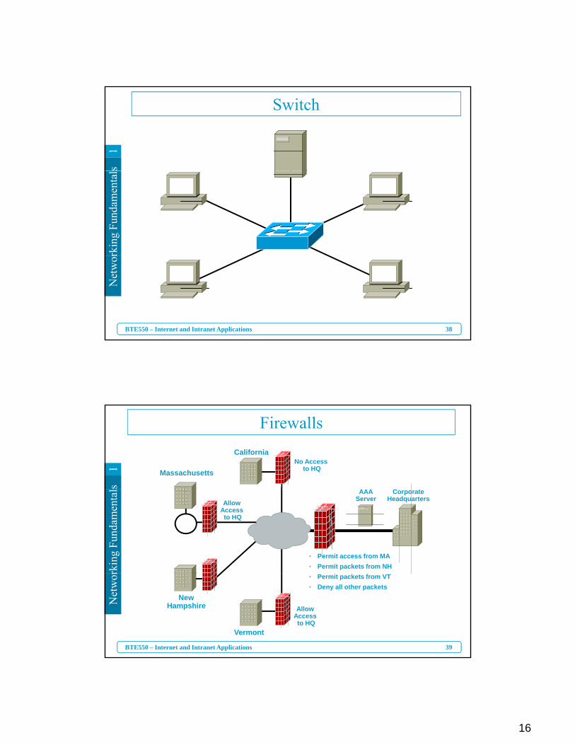
Network Interface Cardrk
ing
Fund
amen
tal
36
Net
wor
BTE550 – Internet and Intranet Applications
s1
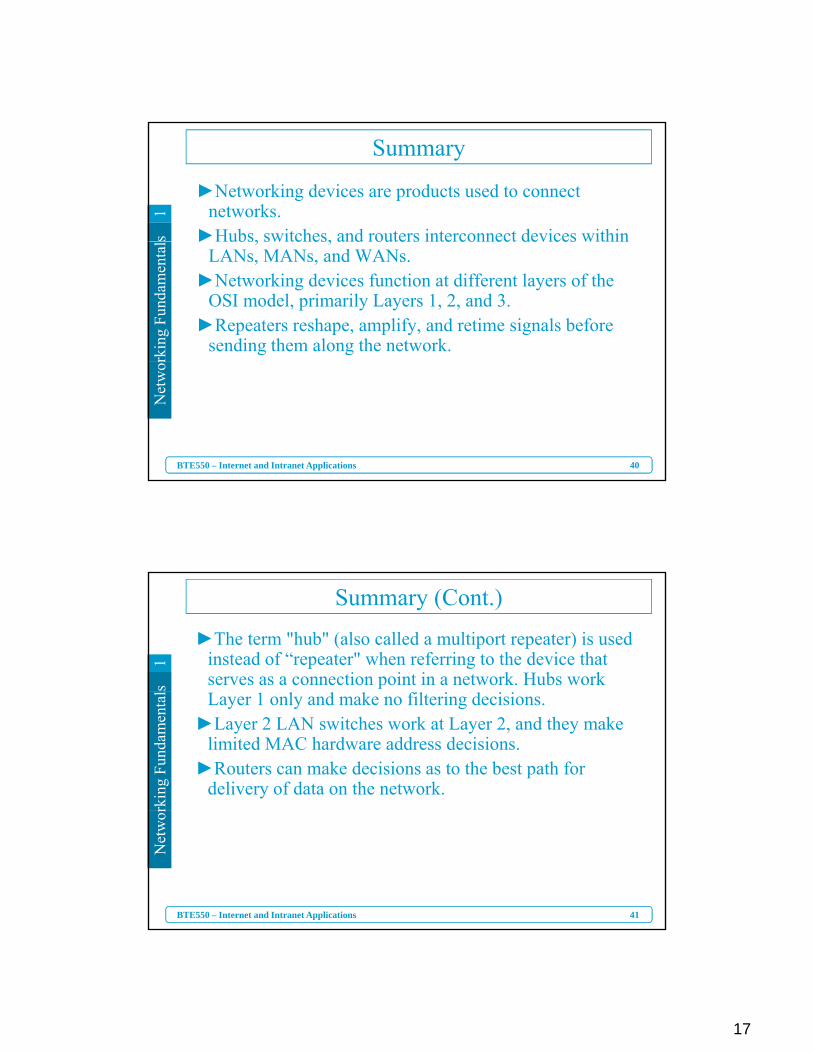
Bridge
rkin
g Fu
ndam
enta
l
S t 2S t 1
37
Net
wor
BTE550 – Internet and Intranet Applications
Segment 2Segment 1CorporateInternet
16
s1
Switchrk
ing
Fund
amen
tal
38
Net
wor
BTE550 – Internet and Intranet Applications
s1
FirewallsCalifornia
MassachusettsNo Access
to HQ
rkin
g Fu
ndam
enta
l
Allow Access to HQ
AAAServer
• Permit access from MA• Permit packets from NH
CorporateHeadquarters
39
Net
wor
BTE550 – Internet and Intranet Applications
Vermont
NewHampshire
• Permit packets from VT• Deny all other packets
Allow Access to HQ
17
s1
Summary
►Networking devices are products used to connect networks.
►Hubs, switches, and routers interconnect devices within
rkin
g Fu
ndam
enta
l ►Hubs, switches, and routers interconnect devices within LANs, MANs, and WANs.
►Networking devices function at different layers of the OSI model, primarily Layers 1, 2, and 3.
►Repeaters reshape, amplify, and retime signals before sending them along the network.
40
Net
wor
BTE550 – Internet and Intranet Applications
s1
Summary (Cont.)
►The term "hub" (also called a multiport repeater) is used instead of “repeater" when referring to the device that serves as a connection point in a network. Hubs work
rkin
g Fu
ndam
enta
l Layer 1 only and make no filtering decisions. ►Layer 2 LAN switches work at Layer 2, and they make
limited MAC hardware address decisions. ►Routers can make decisions as to the best path for
delivery of data on the network.
41
Net
wor
BTE550 – Internet and Intranet Applications
18
s1
Summary (Cont.)►Working at Layers 2, 3, and 4, multilayer switches enable
implementation of Layer 3 QoS and security functionality and perform many of the same functions as routers do, but
rkin
g Fu
ndam
enta
l in hardware.►Voice gateways, DSLAMs, and optical devices are newer
types of network connectivity devices.►Firewalls and AAA servers provide security to the
network.
42
Net
wor
BTE550 – Internet and Intranet Applications
s1
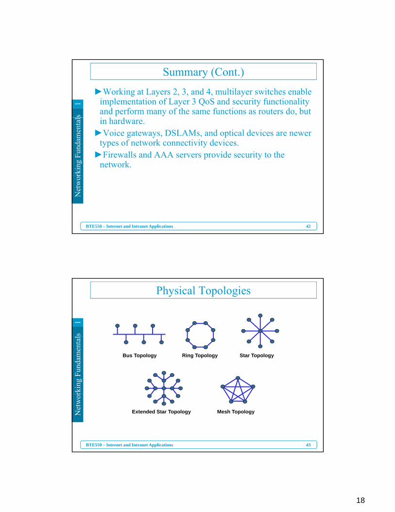
Physical Topologies
rkin
g Fu
ndam
enta
l
Bus Topology Ring Topology Star Topology
43
Net
wor
BTE550 – Internet and Intranet Applications
Mesh TopologyExtended Star Topology
19
s1
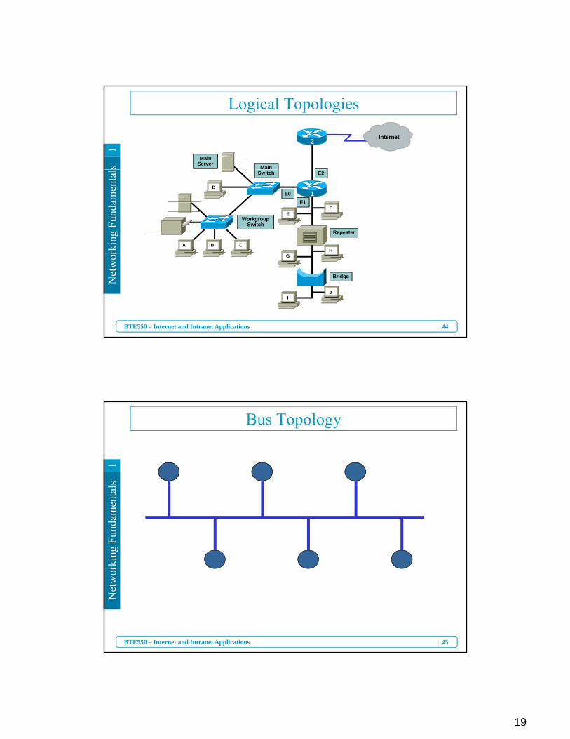
Logical Topologies
Main
Main Server
Internet2
rkin
g Fu
ndam
enta
l
Repeater
WorkgroupSwitch
Switch
D
EF
H
E0
E2
E11
A CB
44
Net
wor
BTE550 – Internet and Intranet Applications
Bridge
G
IJ
s1
Bus Topology
rkin
g Fu
ndam
enta
l
45
Net
wor
BTE550 – Internet and Intranet Applications
20
s1
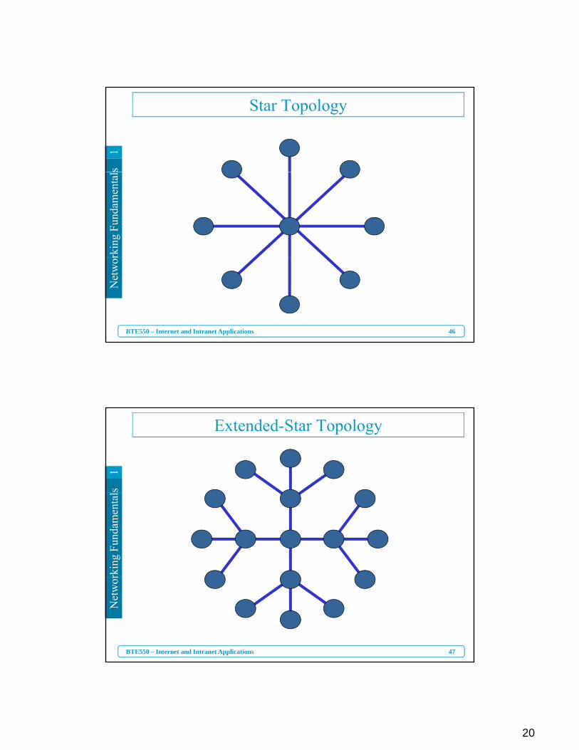
Star Topologyrk
ing
Fund
amen
tal
46
Net
wor
BTE550 – Internet and Intranet Applications
s1
Extended-Star Topology
rkin
g Fu
ndam
enta
l
47
Net
wor
BTE550 – Internet and Intranet Applications
21
s1
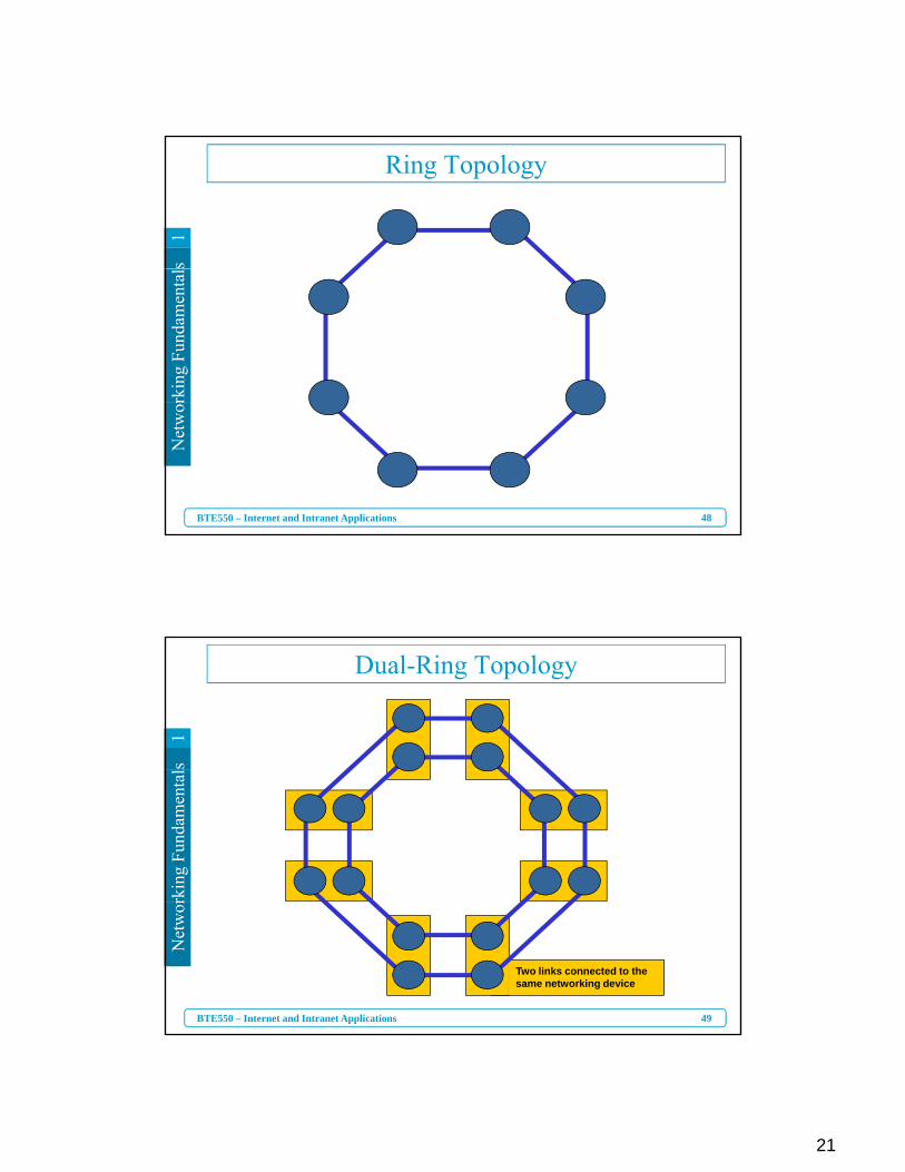
Ring Topologyrk
ing
Fund
amen
tal
48
Net
wor
BTE550 – Internet and Intranet Applications
s1
Dual-Ring Topology
rkin
g Fu
ndam
enta
l
49
Net
wor
BTE550 – Internet and Intranet Applications
Two links connected to thesame networking device
22
s1
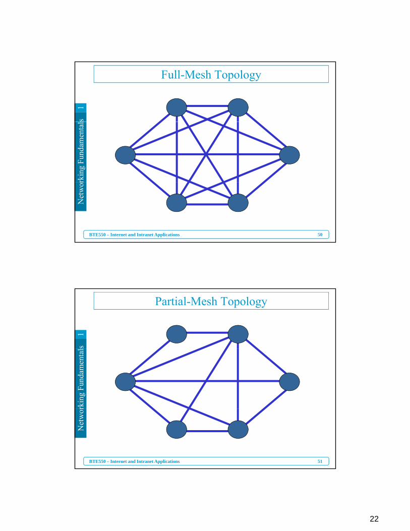
Full-Mesh Topologyrk
ing
Fund
amen
tal
50
Net
wor
BTE550 – Internet and Intranet Applications
s1
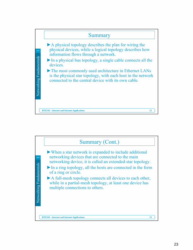
Partial-Mesh Topology
rkin
g Fu
ndam
enta
l
51
Net
wor
BTE550 – Internet and Intranet Applications
23
s1
Summary►A physical topology describes the plan for wiring the
physical devices, while a logical topology describes how information flows through a network.
rkin
g Fu
ndam
enta
l
►In a physical bus topology, a single cable connects all the devices.
►The most commonly used architecture in Ethernet LANs is the physical star topology, with each host in the network connected to the central device with its own cable.
52
Net
wor
BTE550 – Internet and Intranet Applications
s1
Summary (Cont.)
►When a star network is expanded to include additional networking devices that are connected to the main networking device, it is called an extended-star topology.
rkin
g Fu
ndam
enta
l
►In a ring topology, all the hosts are connected in the form of a ring or circle.
►A full-mesh topology connects all devices to each other, while in a partial-mesh topology, at least one device has multiple connections to others.
53
Net
wor
BTE550 – Internet and Intranet Applications
24
s1
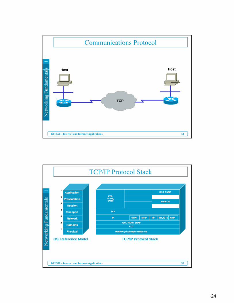
Communications Protocol
Host Host
rkin
g Fu
ndam
enta
l
TCP
Host Host
54
Net
wor
BTE550 – Internet and Intranet Applications
s1
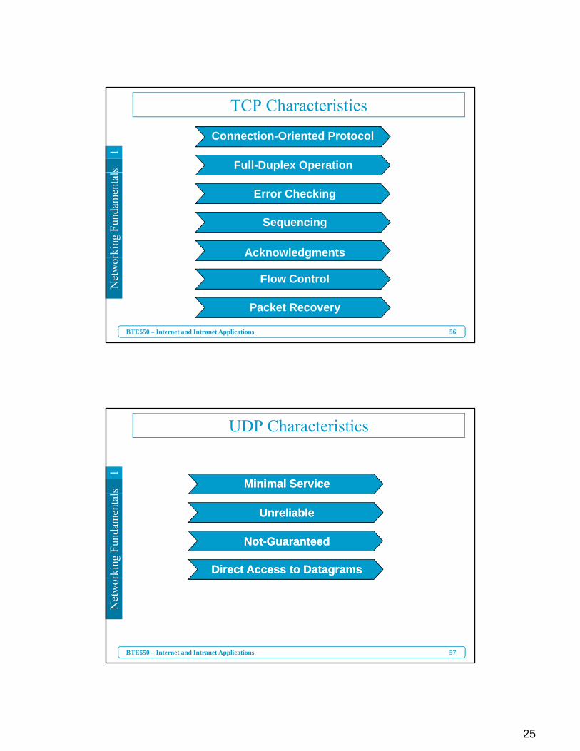
TCP/IP Protocol Stack
FTP,TelnetFTP,
Telnet
DNS, SNMPDNS, SNMP7
6
ApplicationApplication
PresentationPresentation
rkin
g Fu
ndam
enta
l
TCPTCP
ICMPICMP
Telnet,SMTPTelnet,SMTP
IPIP OSPFOSPF IGRPIGRP RIPRIP INT, IS-ISINT, IS-IS
NetBIOSNetBIOS
ARP, RARP, SNAPARP, RARP, SNAPLLCLLC
Many Physical ImplementationsMany Physical Implementations
5
4
3
2
1
PresentationPresentation
SessionSession
TransportTransport
NetworkNetwork
Data-linkData-link
PhysicalPhysical
55
Net
wor
BTE550 – Internet and Intranet Applications
TCP/IP Protocol StackOSI Reference Model
25
s1
TCP Characteristics
Connection-Oriented Protocol
Full-Duplex Operation
rkin
g Fu
ndam
enta
l
Error Checking
Sequencing
Acknowledgments
56
Net
wor
BTE550 – Internet and Intranet Applications
g
Flow Control
Packet Recovery
s1
UDP Characteristics
Minimal ServiceMinimal Service
rkin
g Fu
ndam
enta
l
UnreliableUnreliable
Not-GuaranteedNot-Guaranteed
Direct Access to DatagramsDirect Access to Datagrams
57
Net
wor
BTE550 – Internet and Intranet Applications
26
s1
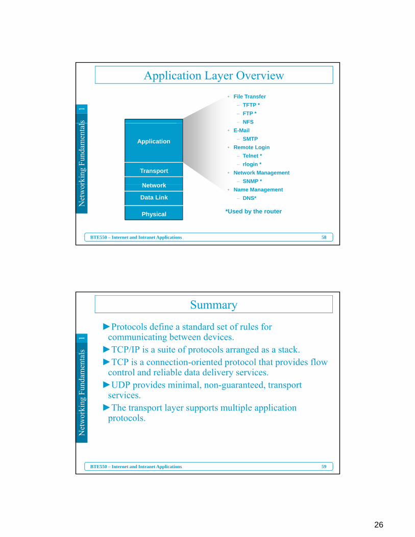
• File Transfer– TFTP *– FTP *– NFS
Application Layer Overviewrk
ing
Fund
amen
tal
Application
Transport
Net ork
NFS• E-Mail
– SMTP• Remote Login
– Telnet *– rlogin *
• Network Management– SNMP *
58
Net
wor
BTE550 – Internet and Intranet Applications
*Used by the router
Network
Data Link
Physical
• Name Management– DNS*
s1
Summary
►Protocols define a standard set of rules for communicating between devices.
►TCP/IP is a suite of protocols arranged as a stack.
rkin
g Fu
ndam
enta
l ►TCP/IP is a suite of protocols arranged as a stack.►TCP is a connection-oriented protocol that provides flow
control and reliable data delivery services.►UDP provides minimal, non-guaranteed, transport
services. ►The transport layer supports multiple application
59
Net
wor
BTE550 – Internet and Intranet Applications
protocols.
27
s1
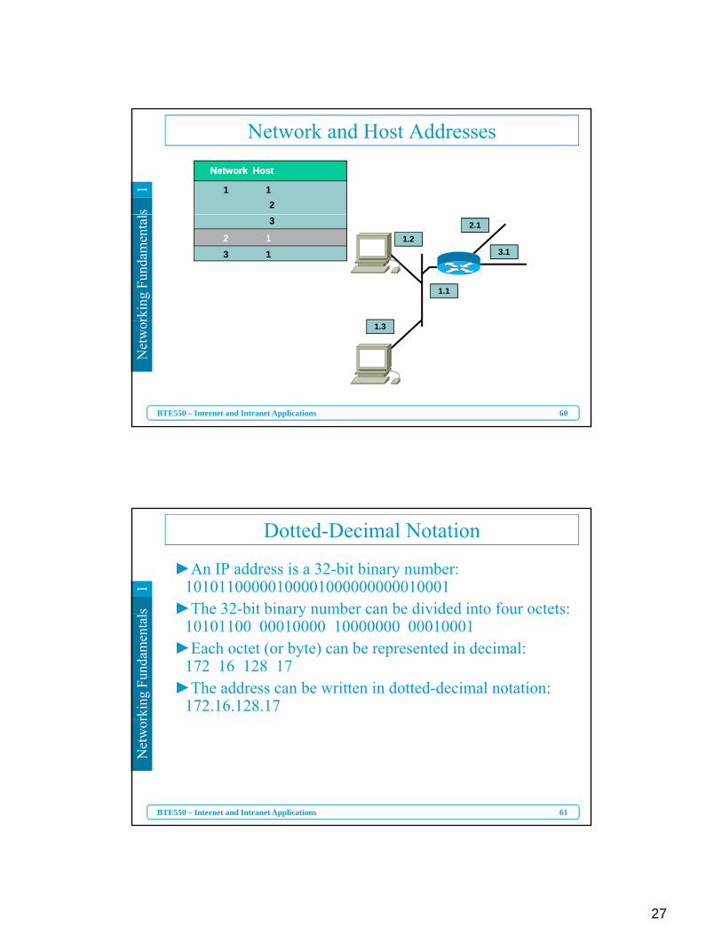
Network and Host Addresses
Network HostNetwork Host
1 12
rkin
g Fu
ndam
enta
l
3.1
2.11.2
1.1
2 13 1
3
60
Net
wor
BTE550 – Internet and Intranet Applications
1.3
s1
Dotted-Decimal Notation
►An IP address is a 32-bit binary number:10101100000100001000000000010001
►The 32-bit binary number can be divided into four octets:
rkin
g Fu
ndam
enta
l ►The 32 bit binary number can be divided into four octets: 10101100 00010000 10000000 00010001
►Each octet (or byte) can be represented in decimal:172 16 128 17
►The address can be written in dotted-decimal notation: 172.16.128.17
61
Net
wor
BTE550 – Internet and Intranet Applications
28
s1
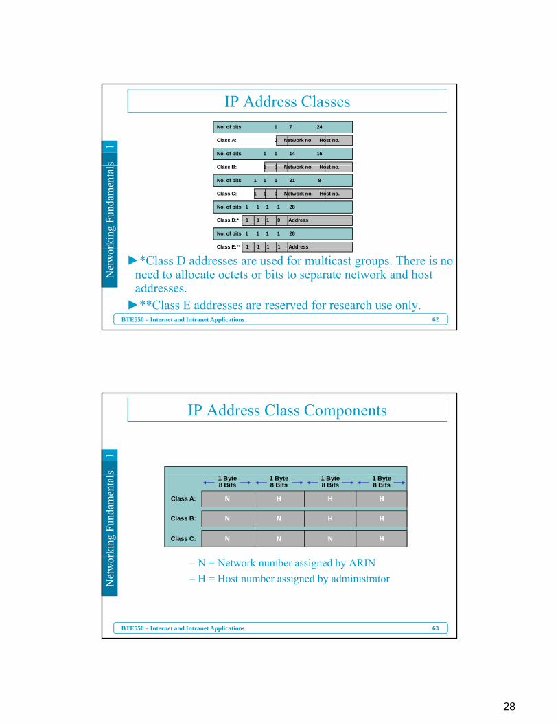
IP Address ClassesNo. of bits 1 7 24
No. of bits 1 1 14 16
Class A: 0 Network no. Host no.
Cl B 1 0 N t k H t
rkin
g Fu
ndam
enta
l
No. of bits 1 1 1 21 8
No. of bits 1 1 1 1 28
No. of bits 1 1 1 1 28
Class B: 1 0 Network no. Host no.
Class C: 1 1 0 Network no. Host no.
Class D:* 1 1 1 0 Address
Class E:** 1 1 1 1 Address
62
Net
wor
BTE550 – Internet and Intranet Applications
►*Class D addresses are used for multicast groups. There is no need to allocate octets or bits to separate network and host addresses.
►**Class E addresses are reserved for research use only.
Class E: 1 1 1 1 Address
s1
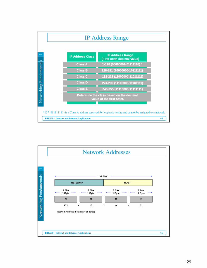
IP Address Class Components
rkin
g Fu
ndam
enta
l
Class A:
Class B:
Class C: NN
HH
1 Byte8 Bits
1 Byte8 Bits
1 Byte8 Bits
1 Byte8 Bits
HH HH
HH HH
HHNN NN
NN NN
NN
63
Net
wor
BTE550 – Internet and Intranet Applications
– N = Network number assigned by ARIN– H = Host number assigned by administrator
29
s1
IP Address Range
IP Address ClassIP Address Class IP Address Range(First octet decimal value)
IP Address Range(First octet decimal value)
rkin
g Fu
ndam
enta
l
Class AClass A
Class BClass B
Class CClass C
Class DClass D
Class EClass E
1-126 (00000001-01111110) *1-126 (00000001-01111110) *
128-191 (10000000-10111111)128-191 (10000000-10111111)
192-223 (11000000-11011111)192-223 (11000000-11011111)
224-239 (11100000-11101111)224-239 (11100000-11101111)
240-255 (11110000-11111111)240-255 (11110000-11111111)
64
Net
wor
BTE550 – Internet and Intranet Applications
*127 (011111111) is a Class A address reserved for loopback testing and cannot be assigned to a network.
Determine the class based on the decimal value of the first octet.
Determine the class based on the decimal value of the first octet.
s1
Network Addresses
32 Bit
rkin
g Fu
ndam
enta
l
172 0016
8 Bits1 Byte
8 Bits1 Byte
8 Bits1 Byte
8 Bits1 Byte
32 Bits
NETWORK HOST
N HN H
• • •
65
Net
wor
BTE550 – Internet and Intranet Applications
Network Address (host bits = all zeros)
30
s1
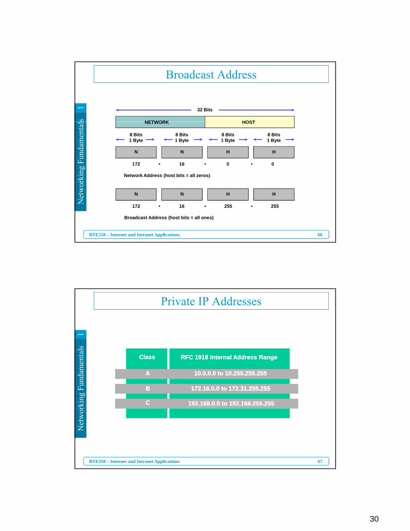
Broadcast Address
32 Bits
NETWORK HOST
rkin
g Fu
ndam
enta
l
172 0016
Network Address (host bits = all zeros)
8 Bits1 Byte
8 Bits1 Byte
8 Bits1 Byte
8 Bits1 Byte
NETWORK HOST
N HN H
• • •
66
Net
wor
BTE550 – Internet and Intranet Applications
Broadcast Address (host bits = all ones)
N HN H
255 255172 16• • •
s1
Private IP Addresses
rkin
g Fu
ndam
enta
l
ClassClass RFC 1918 Internal Address RangeRFC 1918 Internal Address Range
AA
BB
CC
10.0.0.0 to 10.255.255.25510.0.0.0 to 10.255.255.255
172.16.0.0 to 172.31.255.255172.16.0.0 to 172.31.255.255
192.168.0.0 to 192.168.255.255192.168.0.0 to 192.168.255.255
67
Net
wor
BTE550 – Internet and Intranet Applications
31
s1
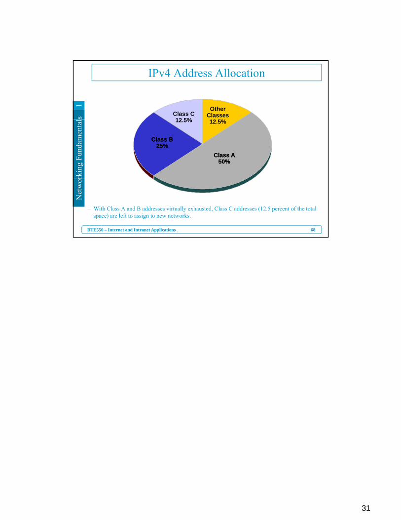
IPv4 Address Allocation
Class C12 5%
Other Classes
rkin
g Fu
ndam
enta
l 12.5%
Class B 25%
Class B 25%
Class A 50%
Class A 50%
12.5%
68
Net
wor
BTE550 – Internet and Intranet Applications
– With Class A and B addresses virtually exhausted, Class C addresses (12.5 percent of the total space) are left to assign to new networks.