Embed Size (px)
Citation preview

Quartetimaging Housing Frame
Guide to Installation and OperationM028-9900-300
Copyright 1999 Miranda Technologies Inc.Specifications may be subject to change.
Printed in CanadaJune 1999
Qua
rtet
imaging Series

WARRANTY POLICIES
Warranty Statement
Miranda Technologies Inc. warrants that the equipment it manufactures shall be free from defects in material andworkmanship for a period of two (2) years from the date of shipment from the factory. If equipment fails due tosuch defects, Miranda Technologies Inc. will, at its option, repair or provide a replacement for the defective part orproduct.
Equipment that fails after the warranty period, has been operated or installed in a manner other than thatspecified by Miranda, or has been subjected to abuse or modification, will be repaired for time and materialcharges at the Buyer’s expense.
All out-of-warranty repairs are warranted for a period of ninety (90) days from the date of shipment from thefactory.
Miranda Technologies Inc. makes no other warranties, expressed or implied, of merchantability, fitness for aparticular purpose or otherwise. Miranda’s liability for any cause, including breach of contract, breach of warranty,or negligence, with respect to products sold by it, is limited to repair or replacement by Miranda, at its solediscretion.
In no event shall Miranda Technologies Inc. be liable for any incidental or consequential damages, including lossof profits.
Effective January 1, 1999
Warranty Exchange Policies
Miranda Technologies Inc. warrants that the equipment it manufactures shall be free from defects in materialsand workmanship for a period of two (2) years from the date of shipment from the factory. If equipment fails dueto such defects, Miranda will provide repair of the failed unit under the terms of the Miranda warranty.
If the equipment has been proven to be defective on arrival, Miranda will ship a new product in exchange, usuallywithin 36 hours of factory notification.
If the equipment to be repaired is essential and the customer so requests, Miranda will, at its option, provide aservice replacement or loaner part or product, usually within 36 hours of factory notification, weekends andholidays excluded.
All warranty exchange or loaner parts or products shall be shipped to the Buyer with a packing list clearlydescribing the items and stating the date of shipment. Repaired parts or products will be shipped to the Buyerwith a similar packing list.
In the case of exchange, the defective products or parts must be returned to Miranda within fifteen (15) days fromreceipt by the customer of the exchange product.
In the case of a loaner, the loaned products or parts must be returned to Miranda within fifteen (15) days fromreceipt by the customer of the repaired equipment.
If the equipment is not returned within fifteen (15) days, as described for either exchanges or loans, A RentalInvoice will be generated. Rental terms will be fifteen (15) percent of the current list price of the products or partsper month or a fraction thereof.
Before returning the equipment to Miranda Technologies Inc., for any reason, the Buyer must first obtain a ReturnAuthorization Number from Miranda Technologies Inc.
Miranda Technologies Inc will pay freight and insurance charges for the delivery of the loaner or exchangeproducts or parts. Freight and insurance charges for the return of the defective product or part will also be paid byMiranda Technologies.
Out-Of-Warranty Repair Policy
Miranda will service out-of-warranty repairs using the following model:
Miranda will charge 10% of the current list price of the product, with a minimum charge of $100.Products whose list price is under $100 will be replaced at a charge equal to current list prices.In the case of obsolete products, the last published list price for the products will apply.

2
In the case of a product deemed beyond repair, the customer must purchase a new product at current retailprices.
All out-of-warranty repairs are warranted for a period of 90 days from the date of shipment from the factory.
Before returning the equipment to Miranda Technologies Inc., for any reason, the Buyer must first obtain a ReturnAuthorization Number from Miranda Technologies Inc.
The Buyer will pay freight and insurance charges for the return of the defective product or part to themanufacturer for repair. Miranda Technologies will pay freight and insurance charges for the return of the repairedproduct or part to the Buyer.
Out-Of Warranty Equipment Updates and Spare Parts Policy
Miranda Technologies will charge cost plus 20% of the parts costs and $40.00 shipping and handling for out-of-warranty equipment updates, or the sales of spare parts.
SAFETY COMPLIANCE
This equipment complies with:
- CSA C22.2 No. 1-94 / Standard for audio, video, and similar electronic equipment.- UL No. 1419 / Standard for professional video and audio equipment.
An appropriately listed mains supply power cord with following characteristics must be usedfor the connection of the equipment.
- Listed 3 pin grounding type- 18/3 AWG, type SVT or SJT
- EN60065: 1993 (EN60065-1:1985/ A2:1989/ A3:1992) Part 1 /European Standard - Safetyrequirements for mains operated and related apparatus for household and similar general use.
ELECTROMAGNETIC COMPATIBILITY
- This equipment has been tested for verification of compliance with FCC Part 15, SubpartB, class A requirements for Digital Devices.
- This equipment complies with the requirements of EN55022 Class A, ElectromagneticEmissions, En 60555-2 & -3, Disturbance in Supply Systems and EN50082-1,Electromagnetic Immunity.
How to contact us:
Head Office Europe
Miranda Technologies Inc. Miranda S.A.2323, Halpern BP 87St-Laurent (Quebec) 93511 Montreuil CedexCanada H4S 1S3 France
Tel.: 1 (514) 333-1772 Tel.: +33 (0) 1 55 86 87 88Fax.: 1 (514) 333-9828 Fax.: +33 (0) 1 55 86 00 29
Toll free: 1-800-224-9828
www.miranda.com

3
CONTENTS
page
1 imaging Quartet Housing frames........................................ 5
1.1 Introduction..................................................................………........... 51.2 Features....................................................................……….............. 5
2 Overview ........................................................…….............. 7
2.1 Front Panel..........................................................………................... 72.2 Rear Panel................................................................……….............. 8
2.2.1 Quartet........................................................……….............. 82.2.2 Quartet-C.......................................................………............ 82.2.3 Quartet-M......................................................………............. 92.2.4 Quartet-A-75.................................................………............. 92.2.5 Quartet-A-110....................................................………........ 102.2.6 Quartet-M-A-75..............................................………............ 102.2.7 Quartet-M-A-110........................................………................ 11
3 Installation......................................................….…....……. 13
3.1 Rack Mount Installation................................................………...........133.2 DC Power Redundancy…………………............................................ 133.3 Power Supply Removal and Installation.............................……….....143.4 RS-422 Serial Connection..............................................……….........163.5 RS-422 Serial ID Assignment.......................................……….......... 173.6 RS-422 Cable Construction.........................................………........... 193.7 Installing an imaging Series Module.........................……….............. 203.8 Removing an imaging Series Module.........................………............ 203.9 Rear Panel Label.......................................................………............. 213.10 Air Filter Removal and Cleaning...............................……….............. 223.11 imaging Extender Module.........................................……….............. 23
4 Power Supply.....................…………………………….……....25
4.1 Powering Up and Local Power Monitoring.............................…….... 254.2 Remote Power Supply Alarm and Cable Construction (optional)…...26
5 Specifications......................................................……….......27

4

5
1 imaging Quartet Housing Frames
1.1 Introduction
The imaging Quartet housing frame family support and provide power to amaximum of 4 imaging series modules in the same single rack unit housing frame.A Quartet, Quartet-C or Quartet-M housing frame can accommodate anycombination of imaging series video modules; a Quartet-A-75, -A-110, -M-A-75 or–M-A-110 housing frame can accommodate any combination of imaging audiomodules (combination of video and audio modules are not possible within the samehousing frame).
Two imaging Quartet housing frames can be interconnected via a rear panelconnector in order to provide power redundancy. In a redundant dual housing frameinstallation, the power supply installed in the second frame is in back-up mode,which maintains DC power levels in case of a local power supply failure. Refer tosection 3.2, DC Power Redundancy for more details.
Some Quartet housing frames are equipped with an RS-422 serial interfaceproviding remote configuration of imaging modules using Miranda's ICP-Sapplication. An RS-422 loop-through allows Quartet housing frames to be daisychained together and controlled by a host computer.
Audio modules can now be installed in Quartet housing frame supporting 75 ohm or110 ohm I/O connections.
1.2 Features
The following features are common to all Quartet housing frames.
• Houses and powers up to 4 imaging series modules• Universal power supply• Front panel status LEDs• 1 RU construction
Table 1.1 indicates the Quartet housing frames which support the followingfeatures.
• ICP-S interface to remote station, allowing up to 16 Quartet, 16 Symphonie,and 16 Solo housing frames to be linked on a single daisy chain providingaccess to up to 336 imaging modules.
• DC power redundancy• Multi-purpose RJ-45 I/O connector• 75 ohm I/O connector• 110 ohm I/O connector• Power supply remote monitoring

6
Table 1.1 imaging Quartet features
ICP-S
Powerredundancy
Power SupplyRemote Monitoring
RJ-45I/O
75 ohmI/O
110 ohmI/O
Quartet * �
Quartet-C �
Quartet-M � � � �
Quartet-A-75 � � � � �
Quartet-A-110 � � � � � �
Quartet-M-A-75 � � � � �
Quartet-M-A-110 � � � � � �
* In this table and in section 2.2.1, the name Quartet designates a basic frame. Frameswith more features are designated by their suffixes such as –C, -M, etc.In this manual, the term Quartet generally refers to all models when installation, powersupply, module installation and similar subjects are concerned.

7
2 Overview
2.1 Front Panel
The front panel consists of 4 mounting holes for rack mount installation, 2 handles,2 thumb screws, and a set of air vents. Make sure the air vents are never blocked.This may cause the housing frame to overheat and possibly breakdown.
To remove the front panel, rotate the thumb screws counter clockwise and pull onthe handles. Referring to Figure 2.1, Quartet houses up to 4 imaging seriesmodules and a power supply. Each module includes a module ejector for easymodule removal. For proper cooling, do not leave the front panel removed for along period of time when power is on.
Figure 2.1 imaging Quartet front panel
Front Panel - Exterior
Handle
Thumb screw
Mounting hole
Air vents
Imaging Quartet
Front Panel - Interior
Power supplyModule #1
Module #3
Module #2
Module #4Module ejector
10

8
2.2 Rear Panel
2.2.1 Quartet
The Quartet rear panel is composed of an AC receptacle, a fan assembly, a DCpower connector for power redundancy, and 32 BNC connectors. The BNCconnectors are combined to form groups of 8. Each group belongs to one of thehousing frame's internal modules. Refer to Figure 2.2 for module and BNCreferencing.
Figure 2.2 Quartet rear panel
AC power connectorFan assembly
DC powerconnector Module #1 connectorsModule #2 connectors
Module #4 connectors Module #3 connectors
2.2.2 Quartet-C
The Quartet-C rear panel is very much similar to that of Quartet's. It is composed ofan AC receptacle, a fan assembly, an ICP-S (RS-422) interface port with loop-through, a rotary switch required for ICP-S serial ID assignments in a daisy chaininstallation, and 32 BNC connectors. The BNC connectors are combined to formgroups of 8. Each group belongs to one of the housing frame's internal modules.Refer to Figure 2.3 for module and BNC referencing.
Figure 2.3 Quartet-C rear panel
Module #1 connectorsModule #2 connectors
Module #4 connectors Module #3 connectors
RS-422 interface portwith loop-through
RS-422
RS-422 serial ID assignmentrotary switch
AC power connectorFan assembly
9
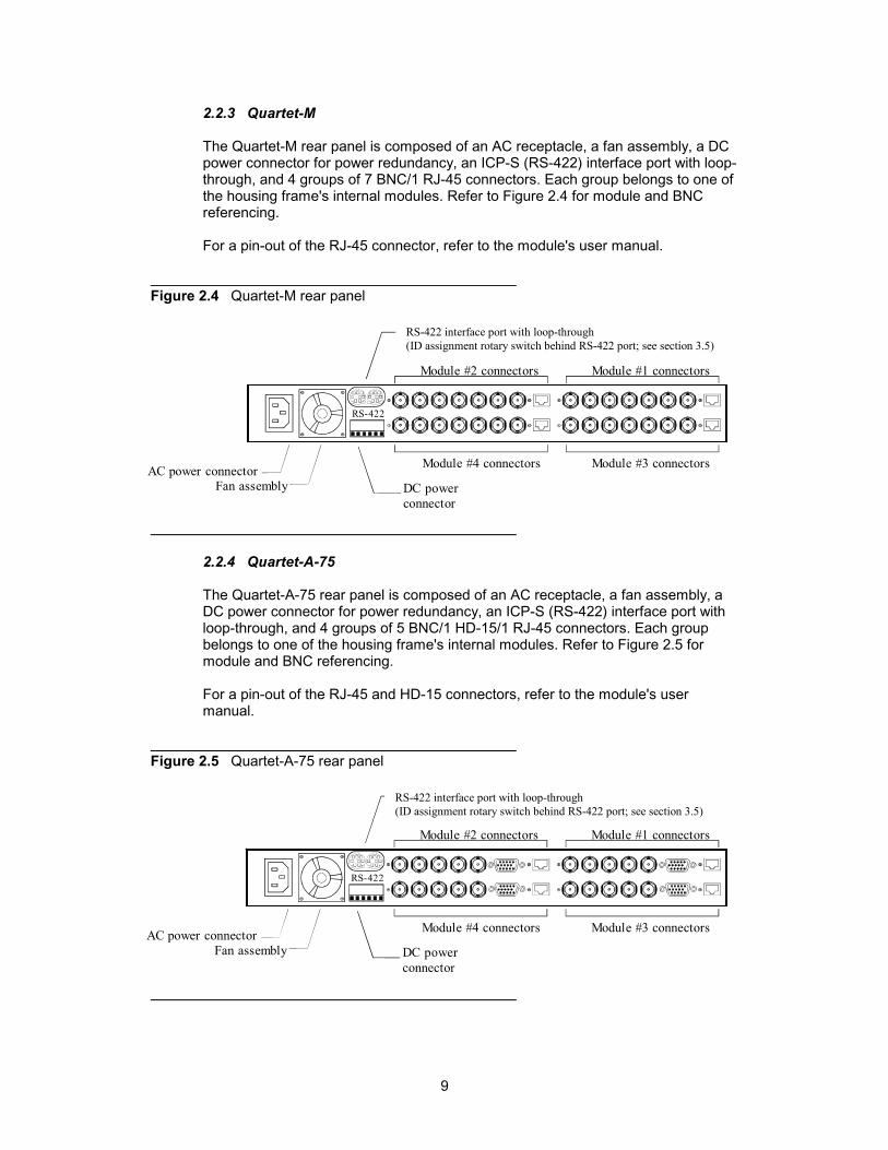
2.2.3 Quartet-M
The Quartet-M rear panel is composed of an AC receptacle, a fan assembly, a DCpower connector for power redundancy, an ICP-S (RS-422) interface port with loop-through, and 4 groups of 7 BNC/1 RJ-45 connectors. Each group belongs to one ofthe housing frame's internal modules. Refer to Figure 2.4 for module and BNCreferencing.
For a pin-out of the RJ-45 connector, refer to the module's user manual.
Figure 2.4 Quartet-M rear panel
2.2.4 Quartet-A-75
The Quartet-A-75 rear panel is composed of an AC receptacle, a fan assembly, aDC power connector for power redundancy, an ICP-S (RS-422) interface port withloop-through, and 4 groups of 5 BNC/1 HD-15/1 RJ-45 connectors. Each groupbelongs to one of the housing frame's internal modules. Refer to Figure 2.5 formodule and BNC referencing.
For a pin-out of the RJ-45 and HD-15 connectors, refer to the module's usermanual.
Figure 2.5 Quartet-A-75 rear panel
Module #1 connectorsModule #2 connectors
Module #4 connectors Module #3 connectorsAC power connectorFan assembly DC power
connector
RS-422
RS-422 interface port with loop-through(ID assignment rotary switch behind RS-422 port; see section 3.5)
Module #1 connectorsModule #2 connectors
Module #4 connectors Module #3 connectorsAC power connectorFan assembly DC power
connector
RS-422
RS-422 interface port with loop-through(ID assignment rotary switch behind RS-422 port; see section 3.5)

10
2.2.5 Quartet-A-110
The Quartet-A-110 rear panel is composed of an AC receptacle, a fan assembly, aDC power connector for power redundancy, an ICP-S (RS-422) interface port withloop-through, and 4 groups of 2 BNC/1 HD-26/1 HD-15/1 RJ-45 connectors. Eachgroup belongs to one of the housing frame's internal modules. Refer to Figure 2.6for module and BNC referencing.
For a pin-out of the RJ-45, HD-15, and HD-26 connectors, refer to the module'suser manual.
Figure 2.6 Quartet-A-110 rear panel
2.2.6 Quartet-M-A-75
The Quartet-M-A-75 rear panel is composed of an AC receptacle, a fan assembly,a DC power connector for power redundancy, an ICP-S (RS-422) interface port withloop-through, 2 groups of 5 BNC/1 HD-15/1 RJ-45 connectors as in the Quartet-A-75, and 2 groups of 7 BNC/1 RJ-45 connectors as in the Quartet-M. Each groupbelongs to one of the housing frame's internal modules. Refer to Figure 2.7 formodule and BNC referencing.
For a pin-out of the RJ-45, and HD-15 connectors, refer to the module's usermanual.
Figure 2.7 Quartet-M-A-75 rear panel
Module #1 connectorsModule #2 connectors
Module #4 connectors Module #3 connectorsAC power connectorFan assembly DC power
connector
RS-422
RS-422 interface port with loop-through(ID assignment rotary switch behind RS-422 port; see section 3.5)
Module #1 connectorsModule #2 connectors
Module #4 connectors Module #3 connectorsAC power connectorFan assembly DC power
connector
RS-422
RS-422 interface port with loop-through(ID assignment rotary switch behind RS-422 port; see section 3.5)
11
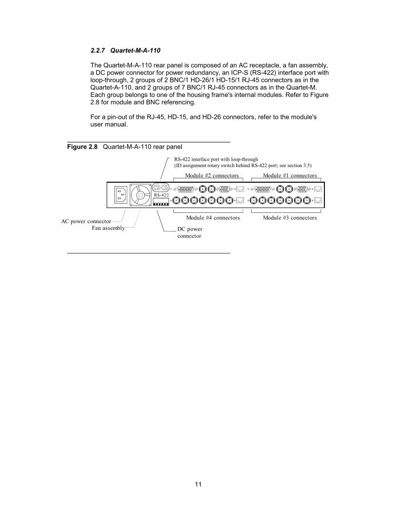
2.2.7 Quartet-M-A-110
The Quartet-M-A-110 rear panel is composed of an AC receptacle, a fan assembly,a DC power connector for power redundancy, an ICP-S (RS-422) interface port withloop-through, 2 groups of 2 BNC/1 HD-26/1 HD-15/1 RJ-45 connectors as in theQuartet-A-110, and 2 groups of 7 BNC/1 RJ-45 connectors as in the Quartet-M.Each group belongs to one of the housing frame's internal modules. Refer to Figure2.8 for module and BNC referencing.
For a pin-out of the RJ-45, HD-15, and HD-26 connectors, refer to the module'suser manual.
Figure 2.8 Quartet-M-A-110 rear panel
Module #1 connectorsModule #2 connectors
Module #4 connectors Module #3 connectorsAC power connectorFan assembly DC power
connector
RS-422
RS-422 interface port with loop-through(ID assignment rotary switch behind RS-422 port; see section 3.5)

12

13
3 Installation
3.1 Rack Mount Installation
Quartet housing frames can be mounted in a standard 19" rack. The unit's frontpanel is secured to the rack by installing the appropriate rack screws and nylonwashers. The front panel's paint finish may be damaged if nylon washers are notused.
For proper ventilation, make sure that the front panel is installed and that the frontpanel air vents and rear panel fan assembly are not blocked when power is on.
3.2 DC Power Redundancy
For those Quartet housing frames supporting DC power redundancy, the externalDC power supply connector may be used to get DC power from a second Quartethousing frame or a Quartet-RPS frame. Interconnecting two Quartet framesequipped with a DC connector is possible if the total power consumption for allimaging modules installed into the two housing frames (for a maximum of 8) doesnot surpass the current capacity of one power supply. To find out how muchcurrent is required for the installed modules, refer to the Specifications section ofthe module’s Guide to Installation and Operation. If the total consumptionsurpasses the current capacity, a dedicated redundant power supply may beinstalled in a Quartet-RPS frame which may hold up to three power suplies forredundancy purpose. In both cases, during normal operation both power suppliesare active. If a power supply fails, the other power supply instantaneously providespower to all modules. The FAIL LED will be switched on in the defective unit toindicate its malfunction. In Quartet-RPS and Quartet frames listed in Table 1.1, adry contact may be wired to a remote monitoring system to indicate the powersupply failure. Refer to section 4 Power Supply for more details.
Figure 3.1 indicates how to interconnect two imaging Quartet housing frames. Referto figures 3.2 and 3.3 for cable construction.
Figure 3.1 Dual Quartet Frame Interconnection
imaging Quartet Tray
imaging Quartet Tray

14
Figure 3.2 describes the cable required to interconnect the Quartet frames. Asshown in this diagram, #18 AWG wires are connected between the two terminalstrips (shipped with the frames) in a pin-to-pin fashion. Make sure the terminalscrews are secured tightly. Figure 3.3 provides the DC connector’s pinout viewedfrom the rear panel of a Quartet frame.
Figure 3.2 DC cable construction
Terminal strip(top view)
Terminal strip(top view)
#18 AWG
Figure 3.3 DC connector pinout
-8V+6VGND GND-15V+15V
External DC connector(Quartet and Quartet RPS rear panels)
3.3 Power Supply Removal and Installation
Follow these steps in order to remove the Quartet power supply.
1. Remove the front panel by rotating the thumb screws counter clockwise. Pull onthe handles.
2. Turn off the power supply by placing the Power switch in the "0" position.
3. Remove the AC power cord from the rear panel.

15
4. Using a flat-edge screwdriver, detach the power supply from the housing frameby unscrewing the power supply retaining screw. The retaining screw is spring-loaded and remains at all times fastened to the power supply.
5. Pull gently on the power supply handle.
Follow these steps in order to install a power supply within a Quartet housing frame.
1. Remove the front panel by rotating the thumb screws counter clockwise. Pull onthe handles.
2. Insert the power supply in its assigned slot and gently push the power supplytowards the rear of the housing frame. Firmly push the power supply in order toattach it to the back plane.
3. Using a flat-edge screwdriver, secure the power supply to the housing frame byscrewing the power supply retaining screw.
4. Install the AC power cord to the rear panel.
16
3.4 RS-422 Serial Connection
For those Quartet housing frames supporting ICP-S, the rear panel includes 2identical RS-422 ports which may be used interchangeably as the source or daisychain loop-through. This port directs communication between a series of housingframes and a remote Windows NT workstation. A module's configuration may bemodified from this workstation without the need to push buttons or position jumpers.Refer to the following steps for a single Quartet or multi-Quartet to remote WindowsNT workstation installation.
Single Quartet Installation:
1. Connect the RS-422 cable of Figure 3.7 between the PC/RS-422 converter andone of the RS-422 ports situated on Quartet's rear panel.
2. Connect the Windows NT workstation and the PC/RS-422 converter with aproper cable. Refer to the converter vendor documentation.
3. The final step in a single Quartet installation is the serial identificationassignment required for the housing frame. Refer to section 3.5 RS-422 SerialID Assignment.
Multi-Quartet Installation:
1. Connect the RS-422 cable of Figure 3.7 between the PC/RS-422 converter andone of the RS-422 ports situated on the first housing frame in the daisy chain.
2. Connect the Windows NT workstation and the PC/RS-422 converter with aproper cable. Refer to the converter vendor documentation.
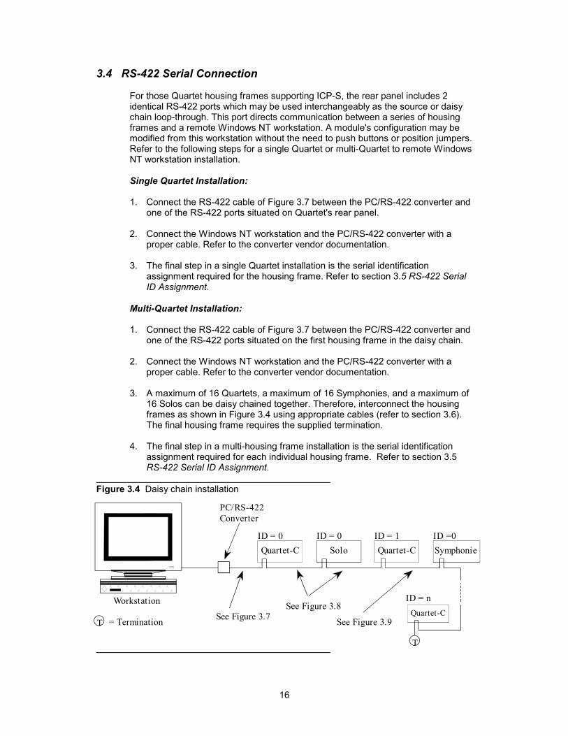
3. A maximum of 16 Quartets, a maximum of 16 Symphonies, and a maximum of16 Solos can be daisy chained together. Therefore, interconnect the housingframes as shown in Figure 3.4 using appropriate cables (refer to section 3.6).The final housing frame requires the supplied termination.
4. The final step in a multi-housing frame installation is the serial identificationassignment required for each individual housing frame. Refer to section 3.5RS-422 Serial ID Assignment.
Figure 3.4 Daisy chain installation
T
PC/RS-422Converter
ID = 0 ID = 0
ID = n
ID = 1 ID =0
See Figure 3.7See Figure 3.8
SymphonieQuartet-CSoloQuartet-C
= TerminationTQuartet-C
Workstation
See Figure 3.9

17
3.5 RS-422 Serial ID Assignment
In a multi-housing frame installation, each frame must be recognized by theworkstation. The only way to accomplish this is to assign an identification code toeach member of the daisy chain. This is similar to assigning different addresses tobuildings on a street. Follow these steps in order to identify each housing frame inthe daisy chain.
Assigning the RS-422 Serial ID on Quartet-C
1. Locate the ID rotary switch on Quartet-C's rear panel. Refer to Figure 3.5.
2. Using a small flat-edge screwdriver, identify each housing frame by setting aunique address to each. The available addresses are 0, 1, 2, 3, 4, 5, 6, 7, 8, 9,A, B, C, D, E, and F producing a total of 16 ID assignments. Two Quartethousing frames cannot have the same address. However, a Quartet housingframe, a Symphonie housing frame and a Solo housing frame can have thesame address.
3. Configure the workstation software to reflect the ID assignments of step 2.
Figure 3.5 Serial ID rotary switch location
RS-422
RS-422 serial ID assignmentrotary switch
Quartet-C rear panel
0 1 2
3 4 5 6 7 8 9 A B C D E F
18
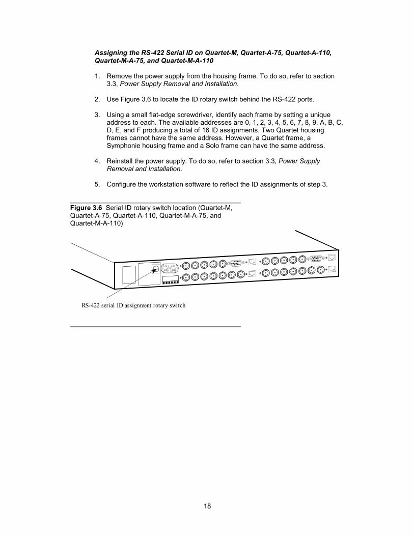
Assigning the RS-422 Serial ID on Quartet-M, Quartet-A-75, Quartet-A-110,Quartet-M-A-75, and Quartet-M-A-110
1. Remove the power supply from the housing frame. To do so, refer to section3.3, Power Supply Removal and Installation.
2. Use Figure 3.6 to locate the ID rotary switch behind the RS-422 ports.
3. Using a small flat-edge screwdriver, identify each frame by setting a uniqueaddress to each. The available addresses are 0, 1, 2, 3, 4, 5, 6, 7, 8, 9, A, B, C,D, E, and F producing a total of 16 ID assignments. Two Quartet housingframes cannot have the same address. However, a Quartet frame, aSymphonie housing frame and a Solo frame can have the same address.
4. Reinstall the power supply. To do so, refer to section 3.3, Power SupplyRemoval and Installation.
5. Configure the workstation software to reflect the ID assignments of step 3.
Figure 3.6 Serial ID rotary switch location (Quartet-M,Quartet-A-75, Quartet-A-110, Quartet-M-A-75, andQuartet-M-A-110)
RS-422 serial ID assignment rotary switch

19
3.6 RS-422 Cable Construction
Figure 3.7 describes the cable required between a Quartet housing frame and thePC/RS-422 converter. The mini-DIN8 connector is viewed from the back where theactual wire connections are to be made. The cable construction required betweenQuartet housing frames is described in Figure 3.8. There is a direct pin-to-pinconnection between mini-DIN8 connectors. Use Figure 3.9 to construct a cable forconnection between Quartet and Symphonie housing frames.
Figure 3.7 Cable between Quartet-C and PC/RS-422 converter
Figure 3.8 Cable between Quartet-C/Solo housing frames
Male Mini-DIN8(viewed from back)
Male Mini-DIN8(viewed from front)
876
5
43
21
0
Figure 3.9 Cable between Quartet-C/Solo and Symphonie housing frames
Male Mini-DIN8(viewed from back)
876
5
43
21
0
RX+
TX+
TX-RX-
PC/RS-422 Converter
RX+
TX+
TX-RX-
1
6
5
94 35
8 6
Mini-Din 8(back of connector)
2 1
7
Male DE-9(back of connector)
S
S=Shield

20
3.7 Installing an imaging Series Module
It is not necessary to switch off the power when installing a module into a housingframe. To install a module, follow these steps.
1. Remove the front panel by rotating the thumb screws counter clockwise. Pull onthe handles.
2. Select an empty slot.
3. Carefully place the module between the module guides (refer to Figure 3.10)and slowly push the module towards the rear of the housing frame until themodule's edge connector is secured to the backplane. Pull lightly on the moduleverifying that it does not move.
4. Replace the front panel. Make sure to rotate the thumb screws clockwise inorder to secure the front panel to the chassis.
Figure 3.10 Module guide location
Module guides
10 Place module here
Place module here
3.8 Removing an imaging Series Module
It is not necessary to switch off the power when removing a module from a housingframe. To remove a module, follow these steps.
1. Remove the front panel by rotating the thumb screws counter clockwise. Pull onthe handles.
2. Locate the module you wish to remove.
3. Carefully pull the module ejector until the module is detached from the internalPCB edge connector. Slowly pull out the module.
4. Replace the front panel. Make sure to rotate the thumb screws clockwise inorder to secure the front panel to the chassis.
21
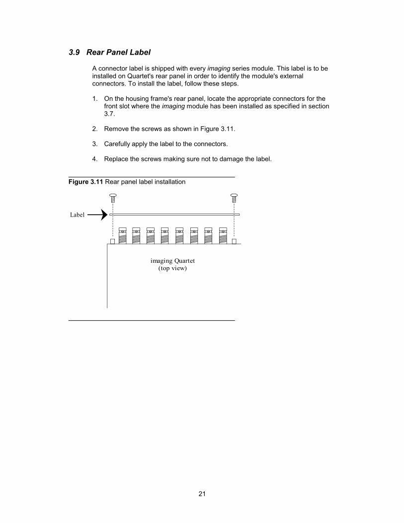
3.9 Rear Panel Label
A connector label is shipped with every imaging series module. This label is to beinstalled on Quartet's rear panel in order to identify the module's externalconnectors. To install the label, follow these steps.
1. On the housing frame's rear panel, locate the appropriate connectors for thefront slot where the imaging module has been installed as specified in section3.7.
2. Remove the screws as shown in Figure 3.11.
3. Carefully apply the label to the connectors.
4. Replace the screws making sure not to damage the label.
Figure 3.11 Rear panel label installation
imaging Quartet(top view)
Label

22
3.10 Air Filter Removal and Cleaning
The imaging housing frame contains a DC powered cooling fan located at the rear.The cooling fan sucks in air via the front panel air vents. Behind the front panel airvents, an air filter prevents dust and air particles from penetrating into the housingframe.
Occasionally, this air filter may have to be removed and properly cleaned in order tomaintain proper ventilation within the housing frame. To remove and clean the airfilter, refer to Figure 3.12 and follow these directions:
1. Remove the front panel by rotating the thumb screws counter clockwise. Pull onthe handles.
2. Carefully remove the lexan membrane and the air filter behind the front panel.
3. Use running water to clean the air filter. Make sure to dry off the air filter beforeattempting to replace it back into its original location.
4. When replacing the air filter, make sure to tuck it back into place behind themetal rails. Reinstall the lexan membrane to block 2/3 of the air filter, as shownon figure 3.12 below.
5. Replace the front panel. Make sure to rotate the thumb screws clockwise inorder to secure the front panel to the chassis.
N.B.: For proper cooling of the imaging modules do not leave the front doorremoved for a long period of time when power is on.
Figure 3.12 Air filter location
Slot Area
Metal rails
Front panel (removed from housing)
Back side of front panell
Air filter
Imaging Quartet
Lexan membrane
23
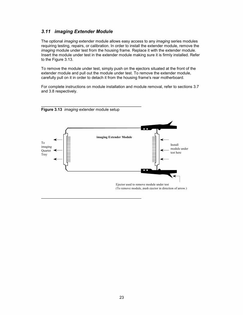
3.11 imaging Extender Module
The optional imaging extender module allows easy access to any imaging series modulesrequiring testing, repairs, or calibration. In order to install the extender module, remove theimaging module under test from the housing frame. Replace it with the extender module.Insert the module under test in the extender module making sure it is firmly installed. Referto the Figure 3.13.
To remove the module under test, simply push on the ejectors situated at the front of theextender module and pull out the module under test. To remove the extender module,carefully pull on it in order to detach it from the housing frame's rear motherboard.
For complete instructions on module installation and module removal, refer to sections 3.7and 3.8 respectively.
Figure 3.13 imaging extender module setup
ToimagingQuartetTray
Installmodule undertest here
imaging Extender Module
Ejector used to remove module under test(To remove module, push ejector in direction of arrow.)

24

25
4 Power Supply
4.1 Powering Up and Local Power Monitoring
To turn on power in a Quartet frame, remove the front panel and place the power switch inthe '1' position. The PWR indicator will light up. The following indicators provide informationon the power supply's status.
• PWR
The PWR LED turns on to indicate the housing frame is powered.
• FAIL
The FAIL LED turns on to indicate that at least one power supply voltage level hasfailed. This may also occur after a thermal shutdown by the power supply. A thermalshutdown occurs at a temperature of 70°C (158°F) setting all output voltage levels to 0.The power supply will restart only when its temperature has dropped to at least 50°C(122°F).
• O/L
This LED lights up to indicate a current overload has been detected on one of the DCpower lines. This indicates a problem with either the power supply or one of the housingframe's modules.
Figure 4.1 Power supply monitoring
PowerFail
Overload
Power switch
10PWR FAIL O/L

26
4.2 Remote Power Failure Alarm and Cable Construction (optional)
The power supply remote monitoring feature in Quartet frames detailed in Table 1.1 informsthe user of a power supply problem. A power failure alarm is provided by the dry contactsof the rear panel mini-Din 8 connector.
Figure 4.2 describes the pinout of the rear panel mini-Din 8 connector. The mini-Din 8connector is viewed from the back where the actual wire connections are to be made. Themini-Din 8 rear panel connector provides a normally closed contact and a normally opencontact. During normal operation, there is a closed contact between pins 1 and 7 and anopen contact between pins 2 and 7. If the power supply fails or experiences a currentoverload, contact between pins 1 and 7 opens and contact between pins 2 and 7 closes.
Figure 4.2 Mini-Din 8 connector pinout (alarm condition)
Male Min-Din 8(viewed from back)
87
6
5
43
21
0
Ground
=Used for RS-422communication (referto section 3.6)

27
5 Specifications
Quartet
I/O connectors: 75 ohm BNC (32)DC power: Terminal strip 6: -8V, +6V, GND, GND, -15V, +15V
Quartet-C
I/O connectors: 75 ohm BNC (32)Serial port: RS-422 on mini-DIN 8 (2)
Quartet-M
I/O connectors: 75 ohm BNC (28)RJ-45 (4)
DC power: Terminal strip 6: -8V, +6V, GND, GND, -15V, +15VSerial port: RS-422 on mini-DIN 8 (2)Power failure alarm: NC contacts on mini-Din 8 (2)
Quartet-A-75
I/O connectors: 75 ohm BNC (20)HD-15 (4)RJ-45 (4)
DC power: Terminal strip 6: -8V, +6V, GND, GND, -15V, +15VSerial port: RS-422 on mini-DIN 8 (2)Power failure alarm: NC contacts on mini-Din 8 (2)
Quartet-A-110
I/O connectors: 75 ohm BNC (8)HD-15 (4)HD-26 (4)RJ-45 (4)
DC power: Terminal strip 6: -8V, +6V, GND, GND, -15V, +15VSerial port: RS-422 on mini-DIN 8 (2)Power failure alarm: NC contacts on mini-Din 8 (2)
Quartet-M-A-75
I/O connectors: 75 ohm BNC (24)HD-15 (2)RJ-45 (4)
DC power: Terminal strip 6: -8V, +6V, GND, GND, -15V, +15VSerial port: RS-422 on mini-DIN 8 (2)Power failure alarm: NC contacts on mini-Din 8 (2)
Quartet-M-A-110
I/O connectors: 75 ohm BNC (18)HD-15 (2)HD-26 (2)
28
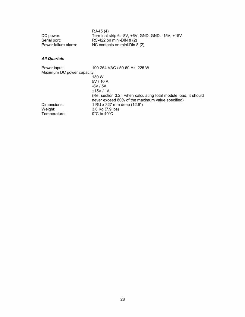
RJ-45 (4)DC power: Terminal strip 6: -8V, +6V, GND, GND, -15V, +15VSerial port: RS-422 on mini-DIN 8 (2)Power failure alarm: NC contacts on mini-Din 8 (2)
All Quartets
Power input: 100-264 VAC / 50-60 Hz, 225 WMaximum DC power capacity:
130 W5V / 10 A-8V / 5A±15V / 1A(Re. section 3.2: when calculating total module load, it shouldnever exceed 80% of the maximum value specified)
Dimensions: 1 RU x 327 mm deep (12.9")Weight: 3.6 Kg (7.9 lbs)Temperature: 0°C to 40°C