Embed Size (px)
Citation preview
Copyright 1999, PRENTICE HALL Chapter 11 1
Intermolecular Forces, Intermolecular Forces, Liquids, and SolidsLiquids, and Solids
Chapter 11Chapter 11
David P. WhiteDavid P. White
University of North Carolina, WilmingtonUniversity of North Carolina, Wilmington
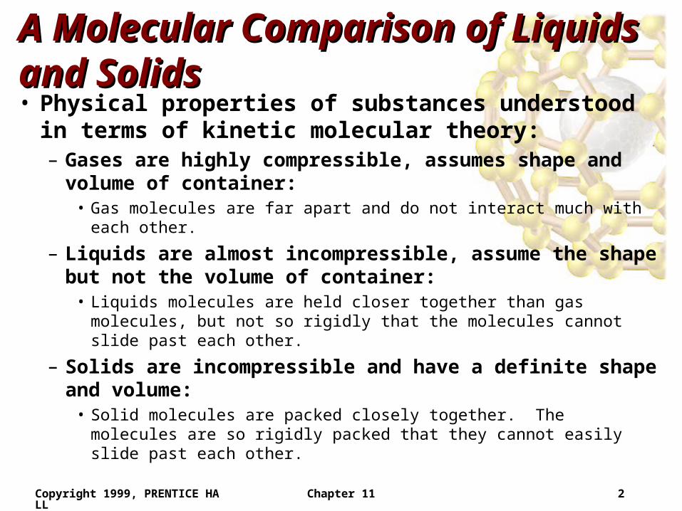
Copyright 1999, PRENTICE HALL Chapter 11 2
A Molecular Comparison of Liquids A Molecular Comparison of Liquids and Solidsand Solids• Physical properties of substances understood in terms
of kinetic molecular theory:– Gases are highly compressible, assumes shape and volume
of container: • Gas molecules are far apart and do not interact much with each other.
– Liquids are almost incompressible, assume the shape but not the volume of container:
• Liquids molecules are held closer together than gas molecules, but not so rigidly that the molecules cannot slide past each other.
– Solids are incompressible and have a definite shape and volume:
• Solid molecules are packed closely together. The molecules are so rigidly packed that they cannot easily slide past each other.
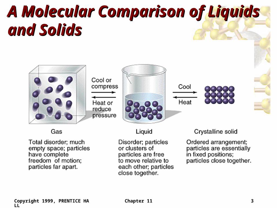
Copyright 1999, PRENTICE HALL Chapter 11 3
A Molecular Comparison of Liquids A Molecular Comparison of Liquids and Solidsand Solids
Copyright 1999, PRENTICE HALL Chapter 11 4
A Molecular Comparison of Liquids A Molecular Comparison of Liquids and Solidsand Solids• Converting a gas into a liquid or solid requires the
molecules to get closer to each other:– cool or compress.
• Converting a solid into a liquid or gas requires the molecules to move further apart: – heat or reduce pressure.
• The forces holding solids and liquids together are called intermolecular forces.
Copyright 1999, PRENTICE HALL Chapter 11 5
Intermolecular ForcesIntermolecular Forces
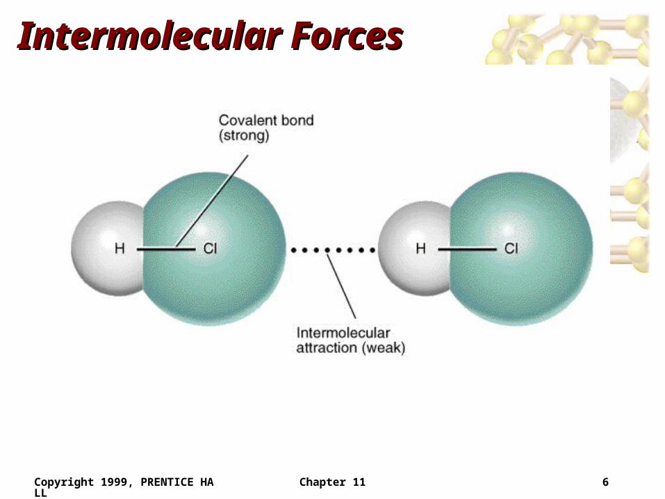
• The covalent bond holding a molecule together is an intramolecular forces.
• The attraction between molecules is an intermolecular force.
• Intermolecular forces are much weaker than intramolecular forces (e.g. 16 kJ/mol vs. 431 kJ/mol for HCl).
• When a substance melts or boils the intermolecular forces are broken (not the covalent bonds).
• When a substance condenses intermolecular forces are formed.
Copyright 1999, PRENTICE HALL Chapter 11 6
Intermolecular ForcesIntermolecular Forces
Copyright 1999, PRENTICE HALL Chapter 11 7
Intermolecular ForcesIntermolecular Forces
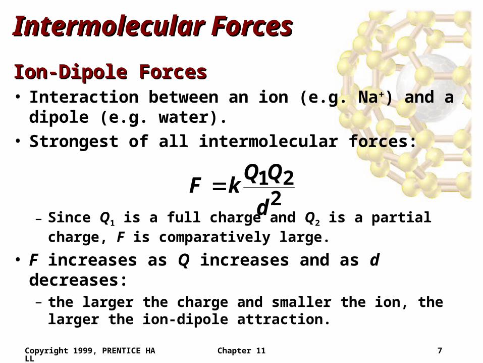
Ion-Dipole ForcesIon-Dipole Forces• Interaction between an ion (e.g. Na+) and a dipole (e.g.
water).• Strongest of all intermolecular forces:
– Since Q1 is a full charge and Q2 is a partial charge, F is comparatively large.
• F increases as Q increases and as d decreases:– the larger the charge and smaller the ion, the larger the ion-
dipole attraction.
221
d
QQkF
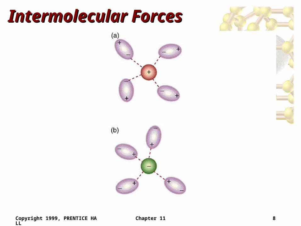
Copyright 1999, PRENTICE HALL Chapter 11 8
Intermolecular ForcesIntermolecular Forces
Copyright 1999, PRENTICE HALL Chapter 11 9
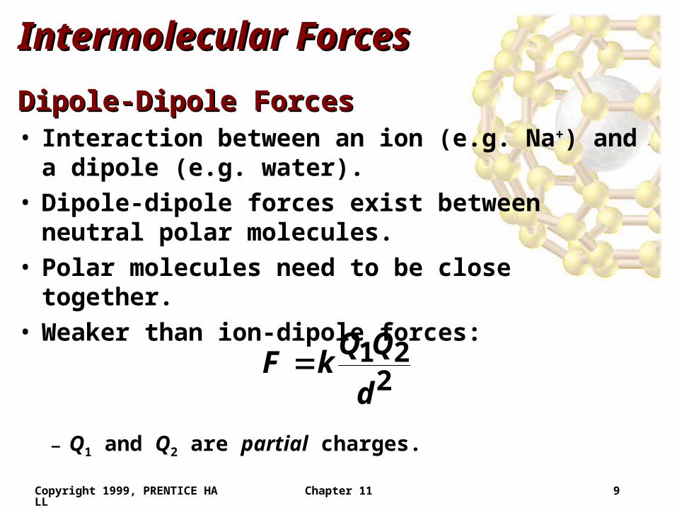
Intermolecular ForcesIntermolecular Forces
Dipole-Dipole ForcesDipole-Dipole Forces• Interaction between an ion (e.g. Na+) and a dipole (e.g.
water).• Dipole-dipole forces exist between neutral polar
molecules.• Polar molecules need to be close together.• Weaker than ion-dipole forces:
– Q1 and Q2 are partial charges.
221
d
QQkF
Copyright 1999, PRENTICE HALL Chapter 11 10
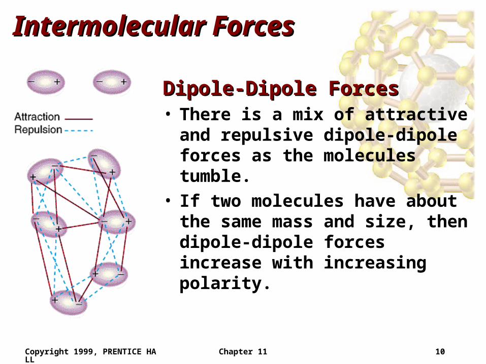
Intermolecular ForcesIntermolecular Forces
Dipole-Dipole ForcesDipole-Dipole Forces• There is a mix of attractive and
repulsive dipole-dipole forces as the molecules tumble.
• If two molecules have about the same mass and size, then dipole-dipole forces increase with increasing polarity.
Copyright 1999, PRENTICE HALL Chapter 11 11
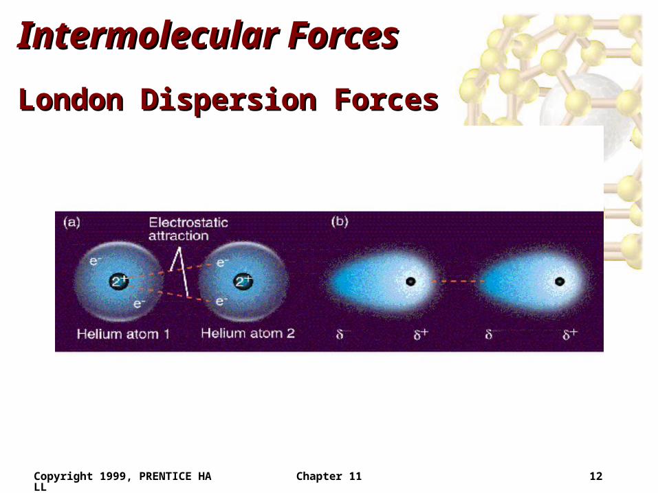
Intermolecular ForcesIntermolecular Forces
London Dispersion ForcesLondon Dispersion Forces• Weakest of all intermolecular forces.• It is possible for two adjacent neutral molecules to
affect each other.• The nucleus of one molecule (or atom) attracts the
electrons of the adjacent molecule (or atom).• For an instant, the electron clouds become distorted.• In that instant a dipole is formed (called an
instantaneous dipole).
Copyright 1999, PRENTICE HALL Chapter 11 12
Intermolecular ForcesIntermolecular Forces
London Dispersion ForcesLondon Dispersion Forces
Copyright 1999, PRENTICE HALL Chapter 11 13
Intermolecular ForcesIntermolecular Forces
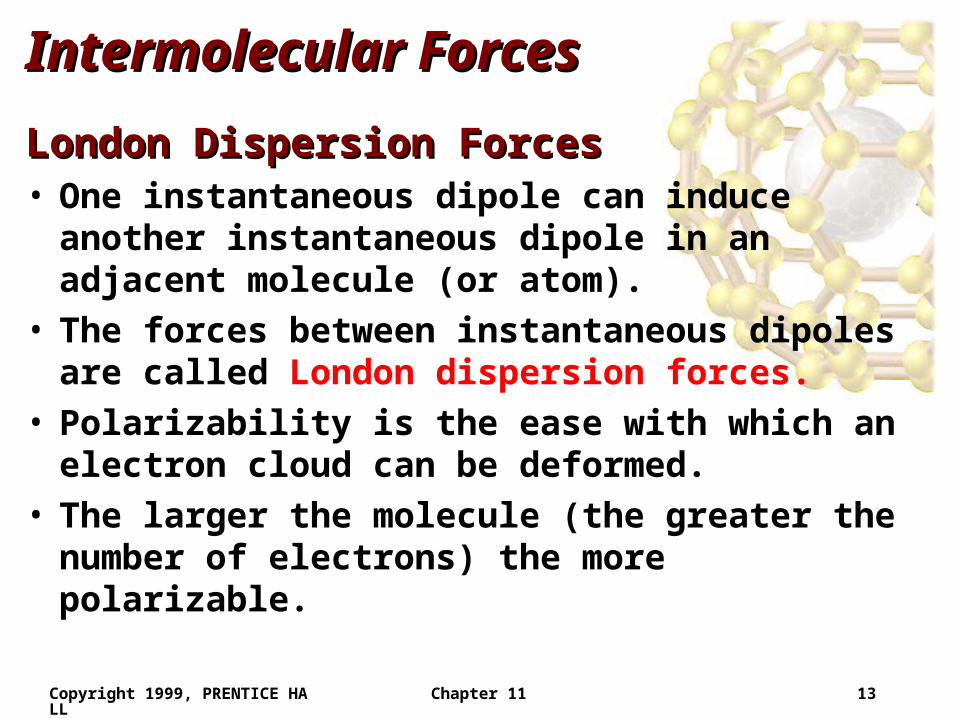
London Dispersion ForcesLondon Dispersion Forces• One instantaneous dipole can induce another
instantaneous dipole in an adjacent molecule (or atom).
• The forces between instantaneous dipoles are called London dispersion forces.
• Polarizability is the ease with which an electron cloud can be deformed.
• The larger the molecule (the greater the number of electrons) the more polarizable.
Copyright 1999, PRENTICE HALL Chapter 11 14
Intermolecular ForcesIntermolecular Forces
London Dispersion ForcesLondon Dispersion Forces
Copyright 1999, PRENTICE HALL Chapter 11 15
Intermolecular ForcesIntermolecular Forces
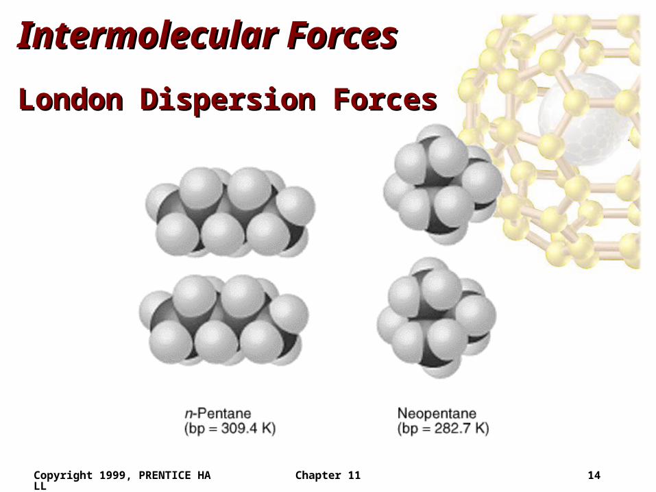
London Dispersion ForcesLondon Dispersion Forces• London dispersion forces increase as molecular
weight increases.• London dispersion forces exist between all molecules.• London dispersion forces depend on the shape of the
molecule.• The greater the surface area available for contact, the
greater the dispersion forces.• London dispersion forces between spherical molecules
are lower than between sausage-like molecules.
Copyright 1999, PRENTICE HALL Chapter 11 16
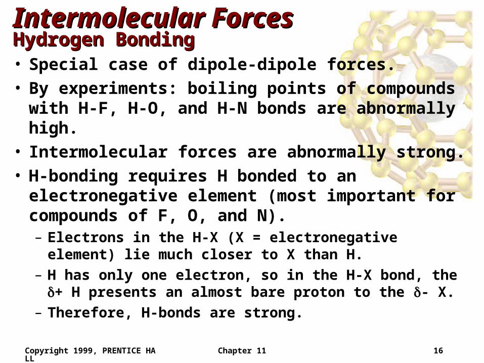
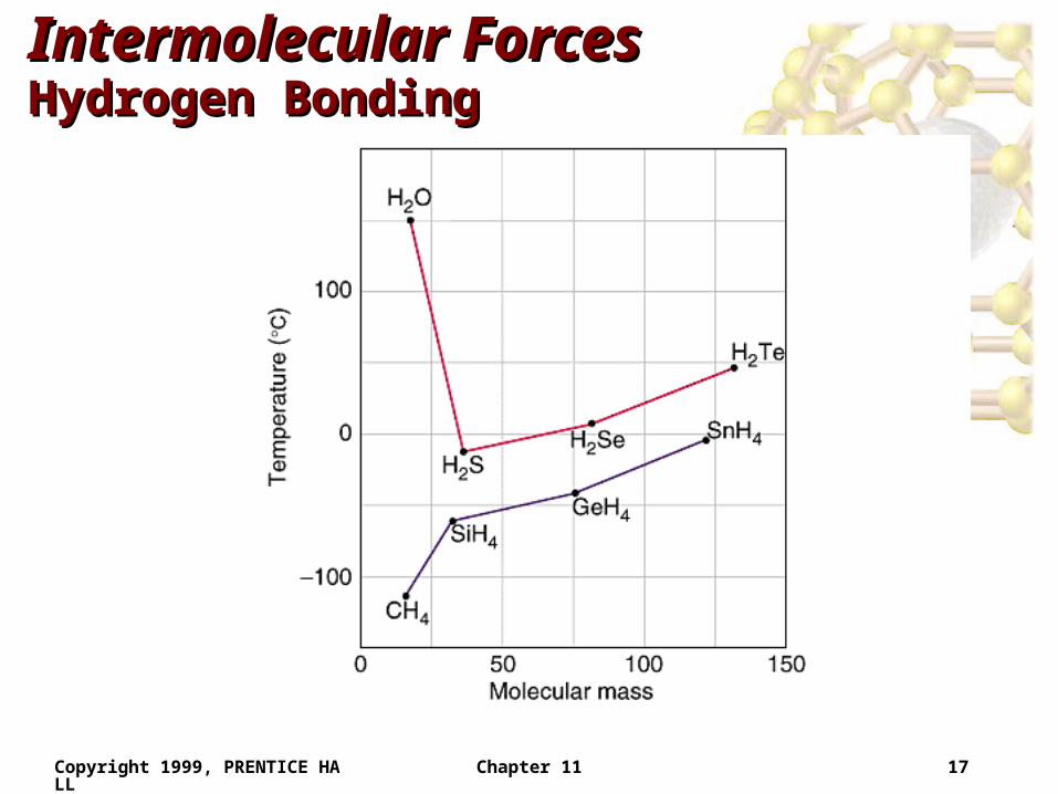
Intermolecular ForcesIntermolecular ForcesHydrogen BondingHydrogen Bonding• Special case of dipole-dipole forces.• By experiments: boiling points of compounds with H-
F, H-O, and H-N bonds are abnormally high.• Intermolecular forces are abnormally strong.• H-bonding requires H bonded to an electronegative
element (most important for compounds of F, O, and N).– Electrons in the H-X (X = electronegative element) lie much
closer to X than H.
– H has only one electron, so in the H-X bond, the + H presents an almost bare proton to the - X.
– Therefore, H-bonds are strong.
Copyright 1999, PRENTICE HALL Chapter 11 17
Intermolecular ForcesIntermolecular ForcesHydrogen BondingHydrogen Bonding
Copyright 1999, PRENTICE HALL Chapter 11 18
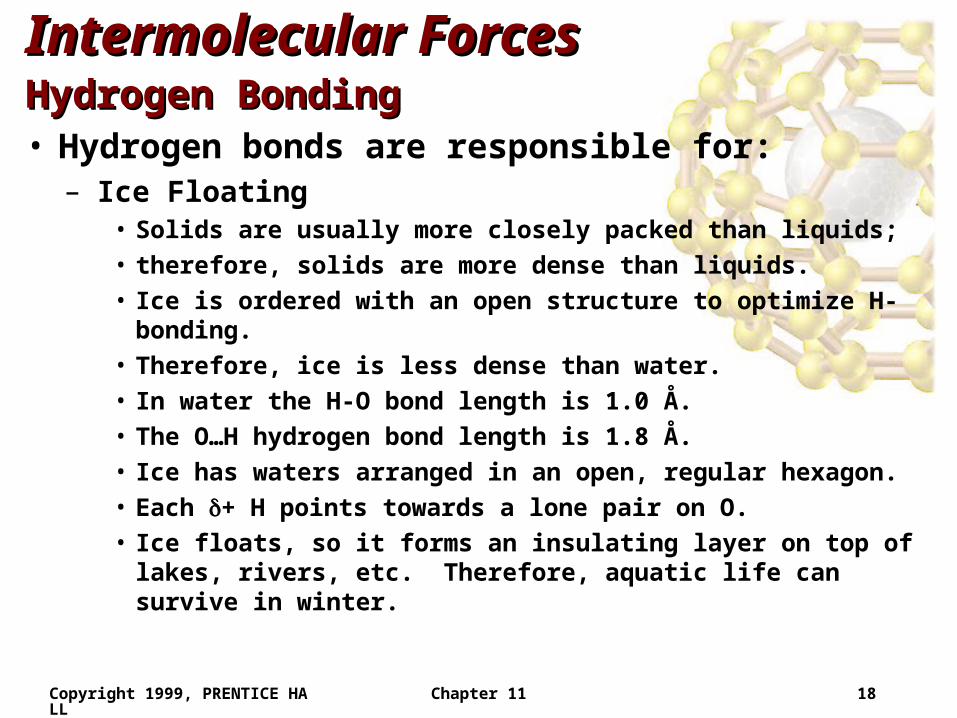
Intermolecular ForcesIntermolecular ForcesHydrogen BondingHydrogen Bonding• Hydrogen bonds are responsible for:
– Ice Floating• Solids are usually more closely packed than liquids;
• therefore, solids are more dense than liquids.
• Ice is ordered with an open structure to optimize H-bonding.
• Therefore, ice is less dense than water.
• In water the H-O bond length is 1.0 Å.
• The O…H hydrogen bond length is 1.8 Å.
• Ice has waters arranged in an open, regular hexagon.
• Each + H points towards a lone pair on O.
• Ice floats, so it forms an insulating layer on top of lakes, rivers, etc. Therefore, aquatic life can survive in winter.
Copyright 1999, PRENTICE HALL Chapter 11 19
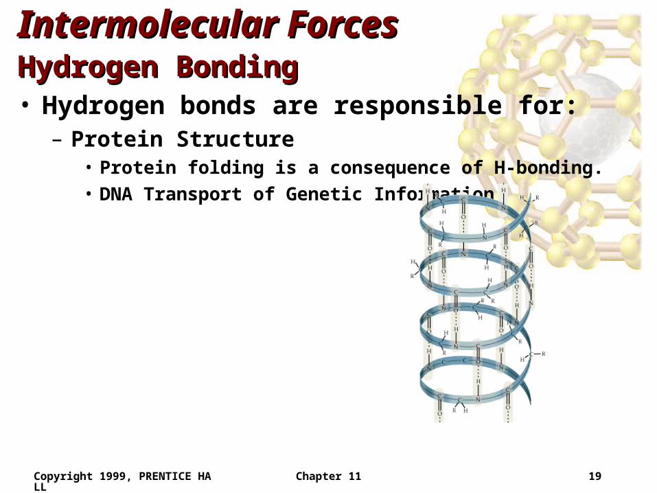
Intermolecular ForcesIntermolecular ForcesHydrogen BondingHydrogen Bonding• Hydrogen bonds are responsible for:
– Protein Structure• Protein folding is a consequence of H-bonding.
• DNA Transport of Genetic Information
Copyright 1999, PRENTICE HALL Chapter 11 20
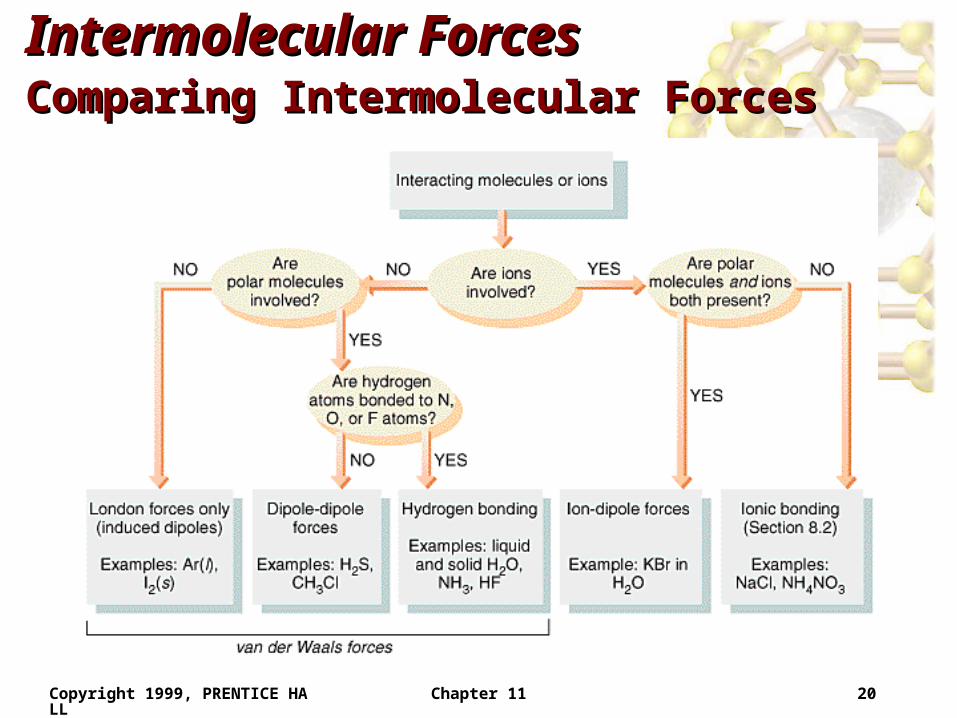
Intermolecular ForcesIntermolecular ForcesComparing Intermolecular ForcesComparing Intermolecular Forces
Copyright 1999, PRENTICE HALL Chapter 11 21
Some Properties of LiquidsSome Properties of Liquids
ViscosityViscosity• Viscosity is the resistance of a liquid to flow.• A liquid flows by sliding molecules over each other.• The stronger the intermolecular forces, the higher the
viscosity.
Surface TensionSurface Tension• Bulk molecules (those in the liquid) are equally
attracted to their neighbors.

Copyright 1999, PRENTICE HALL Chapter 11 22
Some Properties of LiquidsSome Properties of Liquids
Surface TensionSurface Tension
Copyright 1999, PRENTICE HALL Chapter 11 23
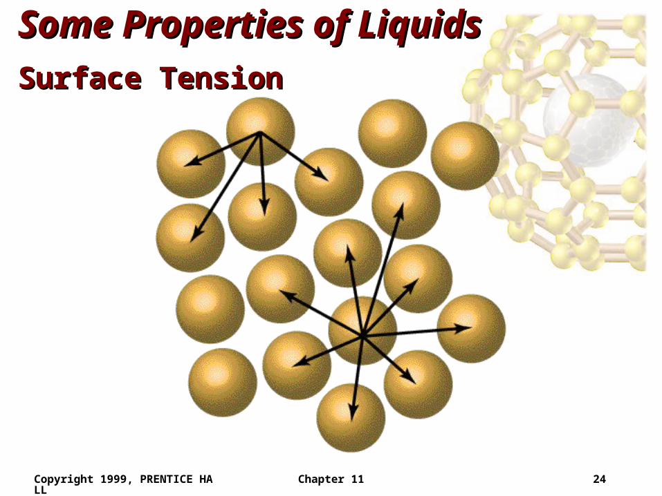
Some Properties of LiquidsSome Properties of Liquids
Surface TensionSurface Tension• Surface molecules are only attracted inwards towards
the bulk molecules.– Therefore, surface molecules are packed more closely than
bulk molecules.
• Surface tension is the amount of energy required to increase the surface area of a liquid.
• Cohesive forces bind molecules to each other.• Adhesive forces bind molecules to a surface.
Copyright 1999, PRENTICE HALL Chapter 11 24
Some Properties of LiquidsSome Properties of Liquids
Surface TensionSurface Tension
Copyright 1999, PRENTICE HALL Chapter 11 25
Some Properties of LiquidsSome Properties of Liquids
Surface TensionSurface Tension• Meniscus is the shape of the liquid surface.
– If adhesive forces are greater than cohesive forces, the liquid surface is attracted to its container more than the bulk molecules. Therefore, the meniscus is U-shaped (e.g. water in glass).
– If cohesive forces are greater than adhesive forces, the meniscus is curved downwards.
• Capillary Action: When a narrow glass tube is placed in water, the meniscus pulls the water up the tube.
Copyright 1999, PRENTICE HALL Chapter 11 26
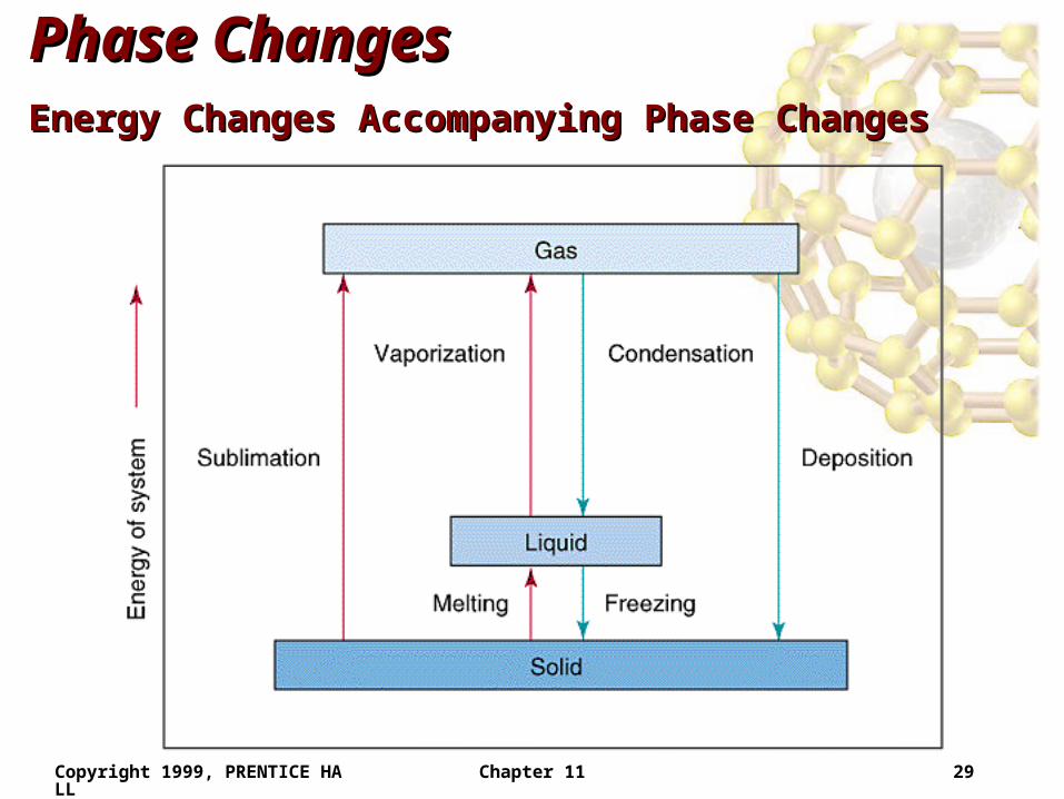
Phase ChangesPhase Changes• Surface molecules are only attracted inwards towards
the bulk molecules.• Sublimation: solid gas.• Vaporization: liquid gas.• Melting or fusion: solid liquid.• Deposition: gas solid.• Condensation: gas liquid.• Freezing: liquid solid.
Energy Changes Accompanying Phase ChangesEnergy Changes Accompanying Phase Changes• Energy change of the system for the above processes
are:
Copyright 1999, PRENTICE HALL Chapter 11 27
Phase ChangesPhase Changes
Energy Changes Accompanying Phase ChangesEnergy Changes Accompanying Phase Changes– Sublimation: Hsub > 0 (endothermic).
– Vaporization: Hvap > 0 (endothermic).
– Melting or Fusion: Hfus > 0 (endothermic).
– Deposition: Hdep < 0 (exothermic).
– Condensation: Hcon < 0 (exothermic).
– Freezing: Hfre < 0 (exothermic).
• Generally heat of fusion (enthalpy of fusion) is less than heat of vaporization:– it takes more energy to completely separate molecules, than
partially separate them.
Copyright 1999, PRENTICE HALL Chapter 11 28
Phase ChangesPhase Changes
Energy Changes Accompanying Phase ChangesEnergy Changes Accompanying Phase Changes• All phase changes are possible under the right
conditions (e.g. water sublimes when snow disappears without forming puddles).
• The sequence
heat solid melt heat liquid boil heat gas
is endothermic.• The sequence
cool gas condense cool liquid freeze cool solid
is exothermic.
Copyright 1999, PRENTICE HALL Chapter 11 29
Phase ChangesPhase Changes
Energy Changes Accompanying Phase ChangesEnergy Changes Accompanying Phase Changes
Copyright 1999, PRENTICE HALL Chapter 11 30
Phase ChangesPhase Changes
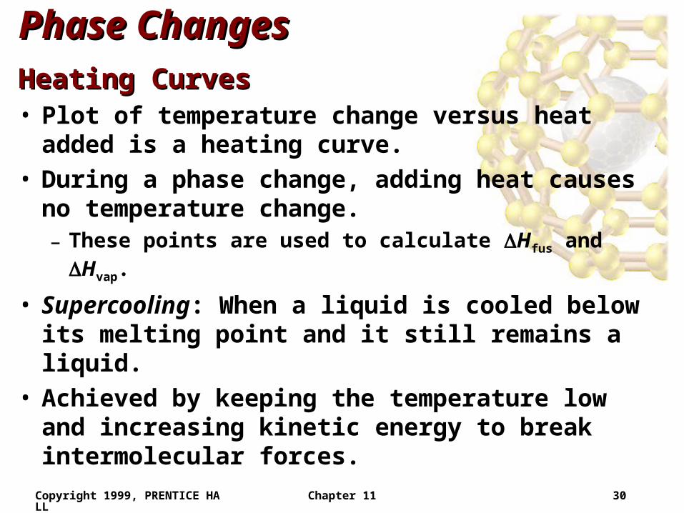
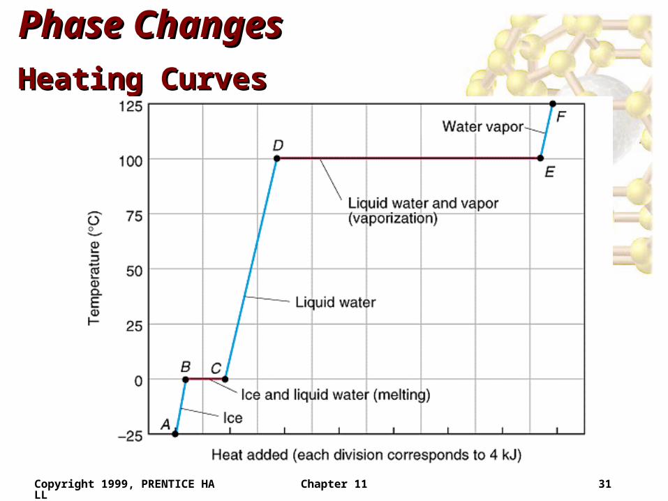
Heating CurvesHeating Curves• Plot of temperature change versus heat added is a
heating curve.• During a phase change, adding heat causes no
temperature change.– These points are used to calculate Hfus and Hvap.
• Supercooling: When a liquid is cooled below its melting point and it still remains a liquid.
• Achieved by keeping the temperature low and increasing kinetic energy to break intermolecular forces.
Copyright 1999, PRENTICE HALL Chapter 11 31
Phase ChangesPhase Changes
Heating CurvesHeating Curves
Copyright 1999, PRENTICE HALL Chapter 11 32
Phase ChangesPhase Changes
Critical Temperature and PressureCritical Temperature and Pressure• Gases liquefied by increasing pressure at some
temperature.• Critical temperature: the minimum temperature for
liquefaction of a gas using pressure.• Critical pressure: pressure required for liquefaction.
Copyright 1999, PRENTICE HALL Chapter 11 33
Vapor PressureVapor Pressure
Explaining Vapor Pressure on the Molecular Explaining Vapor Pressure on the Molecular LevelLevel
• Some of the molecules on the surface of a liquid have enough energy to escape the attraction of the bulk liquid.
• These molecules move into the gas phase.• As the number of molecules in the gas phase
increases, some of the gas phase molecules strike the surface and return to the liquid.
• After some time the pressure of the gas will be constant at the vapor pressure.
Copyright 1999, PRENTICE HALL Chapter 11 34
Vapor PressureVapor Pressure
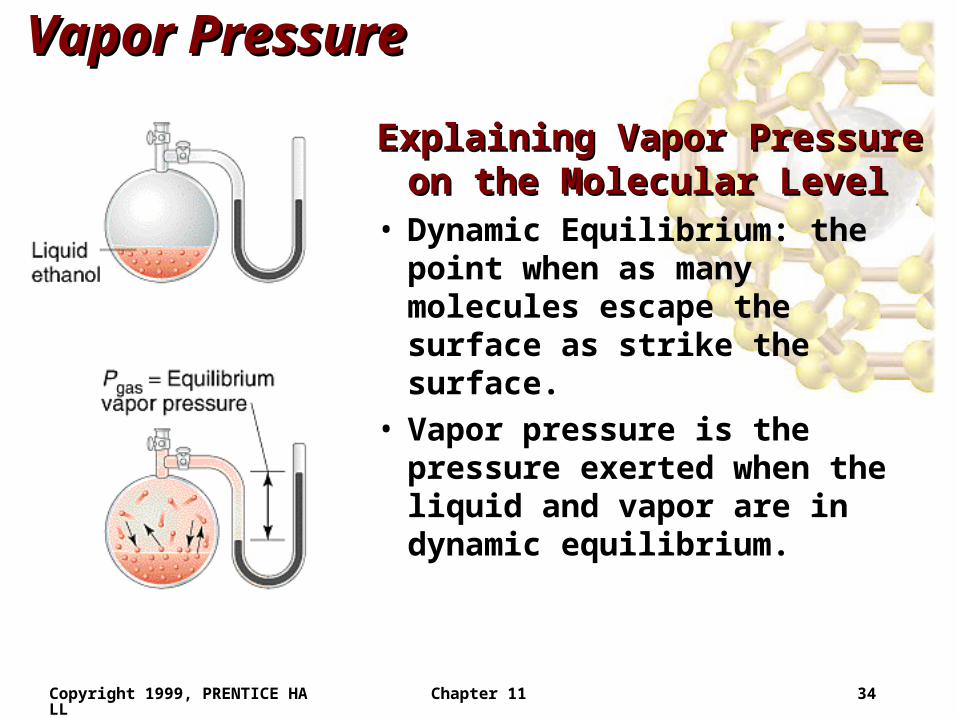
Explaining Vapor Pressure Explaining Vapor Pressure on the Molecular Levelon the Molecular Level
• Dynamic Equilibrium: the point when as many molecules escape the surface as strike the surface.
• Vapor pressure is the pressure exerted when the liquid and vapor are in dynamic equilibrium.
Copyright 1999, PRENTICE HALL Chapter 11 35
Vapor PressureVapor Pressure
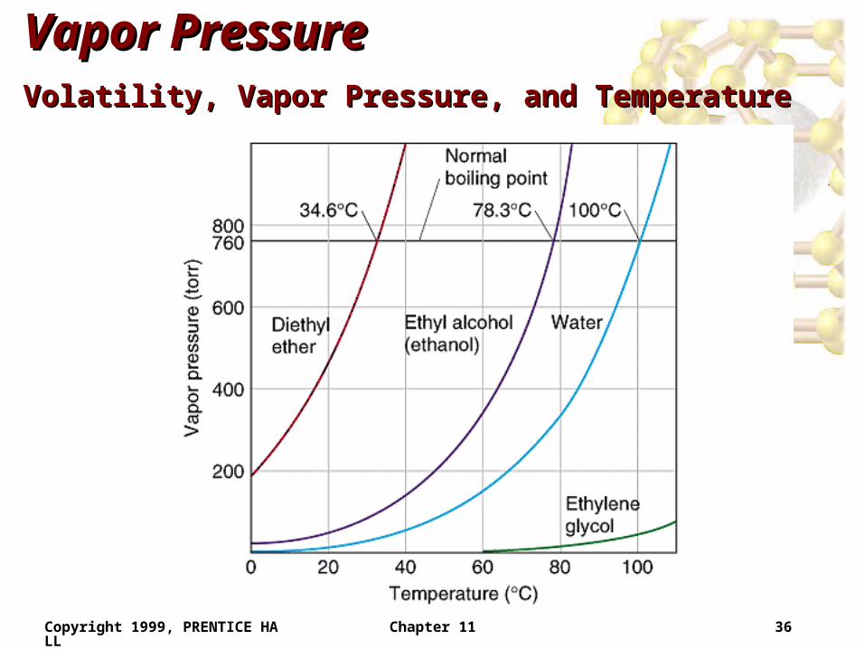
Volatility, Vapor Pressure, and TemperatureVolatility, Vapor Pressure, and Temperature• If equilibrium is never established then the liquid
evaporates.• Volatile substances evaporate rapidly.• The higher the temperature, the higher the average
kinetic energy, the faster the liquid evaporates.
Copyright 1999, PRENTICE HALL Chapter 11 36
Vapor PressureVapor Pressure
Volatility, Vapor Pressure, and TemperatureVolatility, Vapor Pressure, and Temperature
Copyright 1999, PRENTICE HALL Chapter 11 37
Vapor PressureVapor PressureVapor Pressure and Boiling PointVapor Pressure and Boiling Point• Liquids boil when the external pressure equals the
vapor pressure.• Temperature of boiling point increases as pressure
increases.• Two ways to get a liquid to boil: increase temperature
or decrease pressure.– Pressure cookers operate at high pressure. At high
pressure the boiling point of water is higher than at 1 atm. Therefore, there is a higher temperature at which the food is cooked, reducing the cooking time required.
• Normal boiling point is the boiling point at 760 mmHg (1 atm).
Copyright 1999, PRENTICE HALL Chapter 11 38
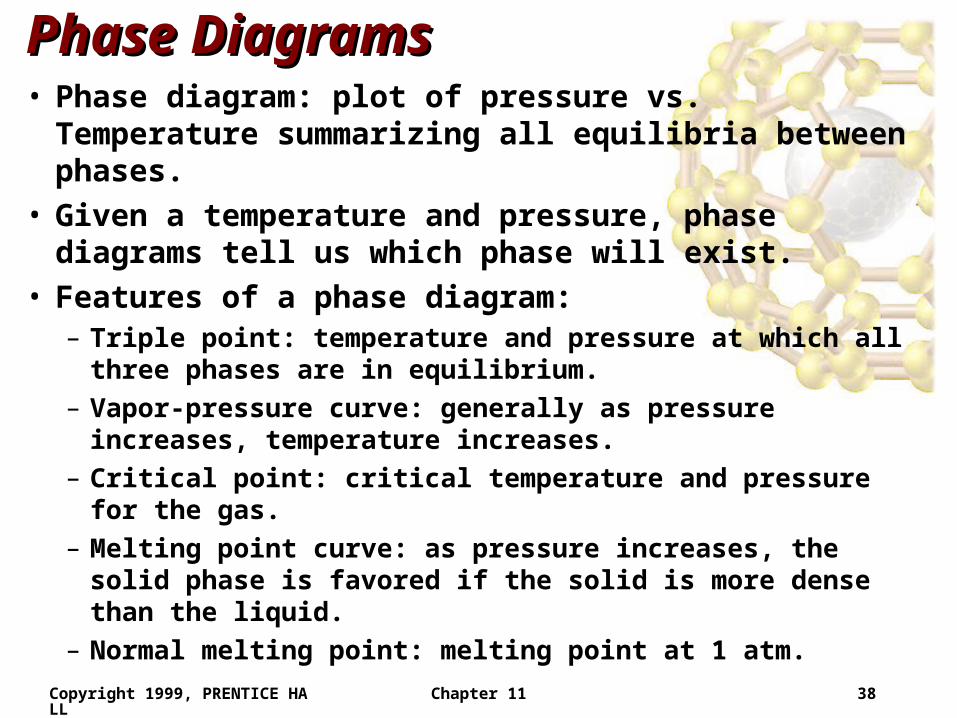
Phase DiagramsPhase Diagrams• Phase diagram: plot of pressure vs. Temperature
summarizing all equilibria between phases.• Given a temperature and pressure, phase diagrams
tell us which phase will exist.• Features of a phase diagram:
– Triple point: temperature and pressure at which all three phases are in equilibrium.
– Vapor-pressure curve: generally as pressure increases, temperature increases.
– Critical point: critical temperature and pressure for the gas.
– Melting point curve: as pressure increases, the solid phase is favored if the solid is more dense than the liquid.
– Normal melting point: melting point at 1 atm.
Copyright 1999, PRENTICE HALL Chapter 11 39
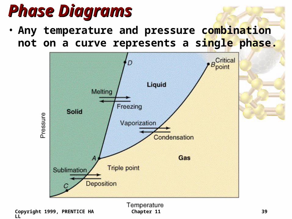
Phase DiagramsPhase Diagrams• Any temperature and pressure combination not on a
curve represents a single phase.
Copyright 1999, PRENTICE HALL Chapter 11 40
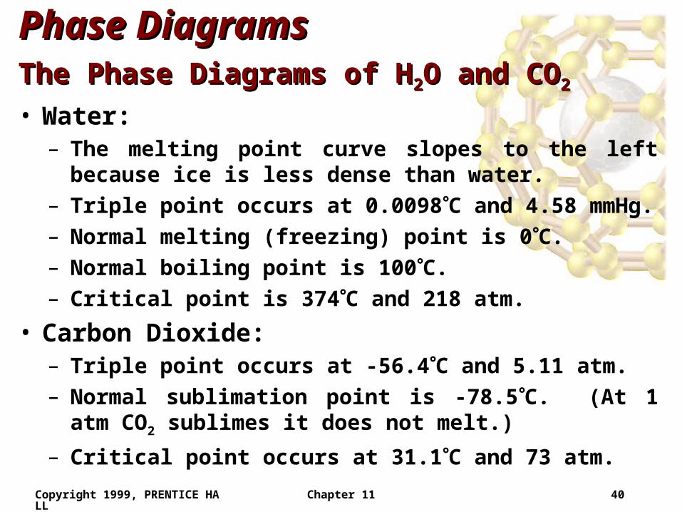
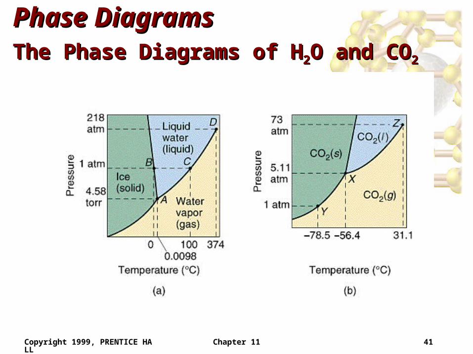
Phase DiagramsPhase DiagramsThe Phase Diagrams of HThe Phase Diagrams of H22O and COO and CO22
• Water:– The melting point curve slopes to the left because ice is less
dense than water.
– Triple point occurs at 0.0098C and 4.58 mmHg.
– Normal melting (freezing) point is 0C.
– Normal boiling point is 100C.
– Critical point is 374C and 218 atm.
• Carbon Dioxide:– Triple point occurs at -56.4C and 5.11 atm.
– Normal sublimation point is -78.5C. (At 1 atm CO2 sublimes it does not melt.)
– Critical point occurs at 31.1C and 73 atm.
Copyright 1999, PRENTICE HALL Chapter 11 41
Phase DiagramsPhase DiagramsThe Phase Diagrams of HThe Phase Diagrams of H22O and COO and CO22
Copyright 1999, PRENTICE HALL Chapter 11 42
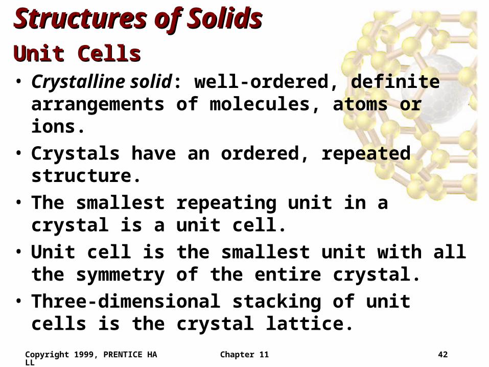
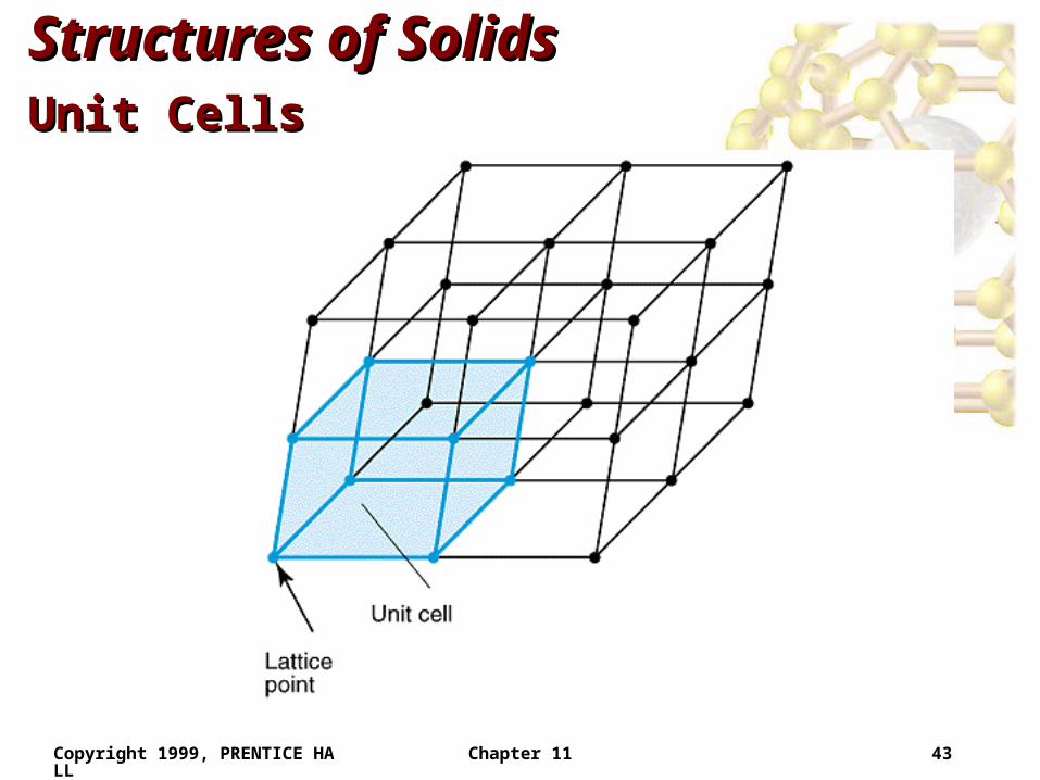
Structures of SolidsStructures of SolidsUnit CellsUnit Cells• Crystalline solid: well-ordered, definite arrangements
of molecules, atoms or ions. • Crystals have an ordered, repeated structure.• The smallest repeating unit in a crystal is a unit cell.• Unit cell is the smallest unit with all the symmetry of
the entire crystal.• Three-dimensional stacking of unit cells is the crystal
lattice.
Copyright 1999, PRENTICE HALL Chapter 11 43
Structures of SolidsStructures of SolidsUnit CellsUnit Cells
Copyright 1999, PRENTICE HALL Chapter 11 44
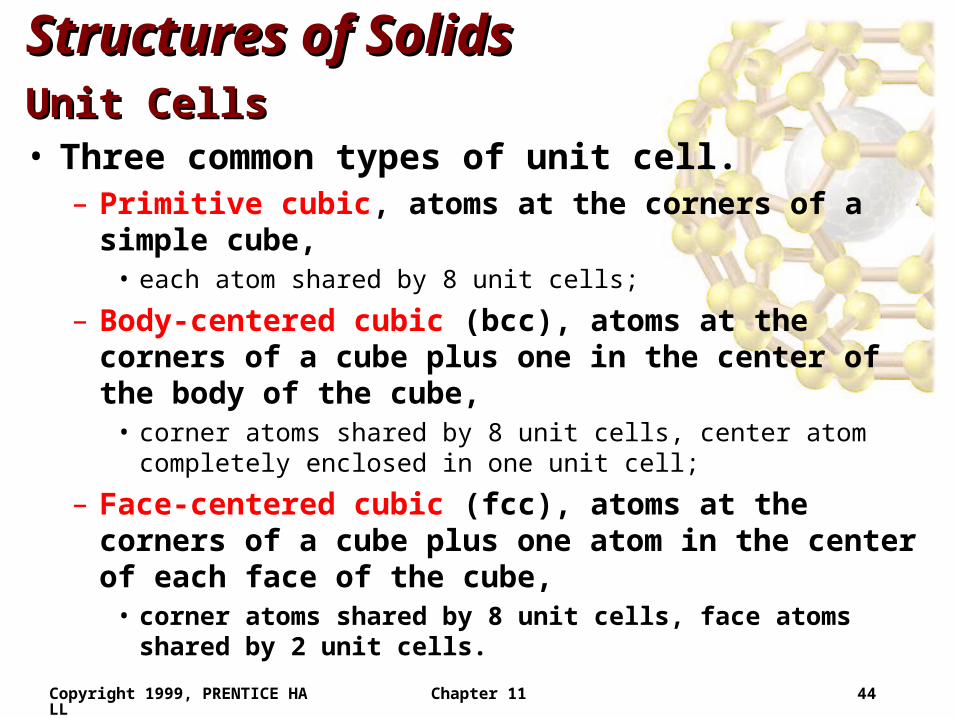
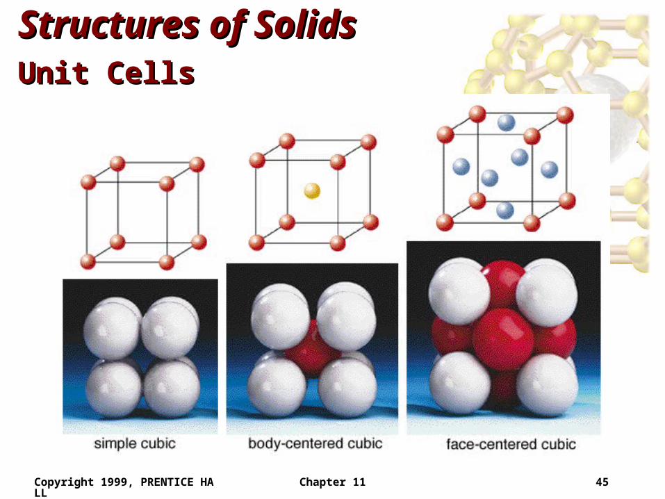
Structures of SolidsStructures of SolidsUnit CellsUnit Cells• Three common types of unit cell.
– Primitive cubic, atoms at the corners of a simple cube,• each atom shared by 8 unit cells;
– Body-centered cubic (bcc), atoms at the corners of a cube plus one in the center of the body of the cube,
• corner atoms shared by 8 unit cells, center atom completely enclosed in one unit cell;
– Face-centered cubic (fcc), atoms at the corners of a cube plus one atom in the center of each face of the cube,
• corner atoms shared by 8 unit cells, face atoms shared by 2 unit cells.
Copyright 1999, PRENTICE HALL Chapter 11 45
Structures of SolidsStructures of SolidsUnit CellsUnit Cells
Copyright 1999, PRENTICE HALL Chapter 11 46
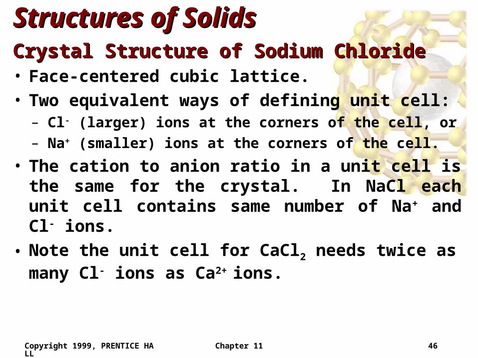
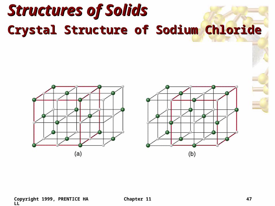
Structures of SolidsStructures of SolidsCrystal Structure of Sodium ChlorideCrystal Structure of Sodium Chloride• Face-centered cubic lattice.• Two equivalent ways of defining unit cell:
– Cl- (larger) ions at the corners of the cell, or
– Na+ (smaller) ions at the corners of the cell.
• The cation to anion ratio in a unit cell is the same for the crystal. In NaCl each unit cell contains same number of Na+ and Cl- ions.
• Note the unit cell for CaCl2 needs twice as many Cl- ions as Ca2+ ions.
Copyright 1999, PRENTICE HALL Chapter 11 47
Structures of SolidsStructures of SolidsCrystal Structure of Sodium ChlorideCrystal Structure of Sodium Chloride
Copyright 1999, PRENTICE HALL Chapter 11 48
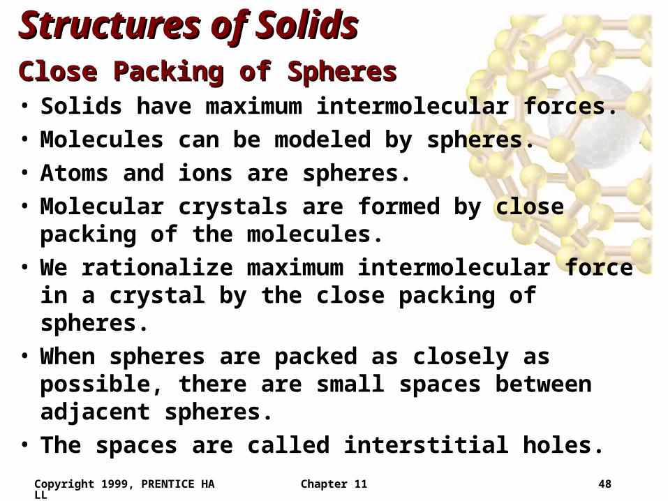
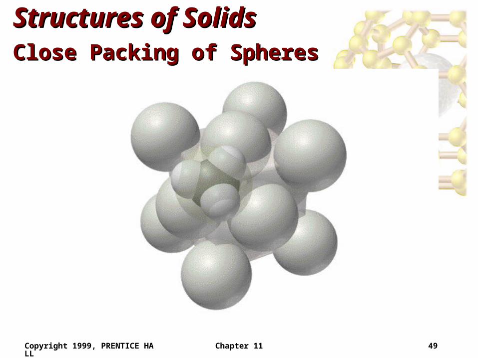
Structures of SolidsStructures of SolidsClose Packing of SpheresClose Packing of Spheres• Solids have maximum intermolecular forces.• Molecules can be modeled by spheres.• Atoms and ions are spheres.• Molecular crystals are formed by close packing of the
molecules.• We rationalize maximum intermolecular force in a
crystal by the close packing of spheres.• When spheres are packed as closely as possible, there
are small spaces between adjacent spheres.• The spaces are called interstitial holes.
Copyright 1999, PRENTICE HALL Chapter 11 49
Structures of SolidsStructures of SolidsClose Packing of SpheresClose Packing of Spheres
Copyright 1999, PRENTICE HALL Chapter 11 50
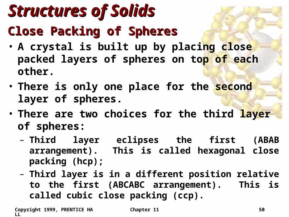
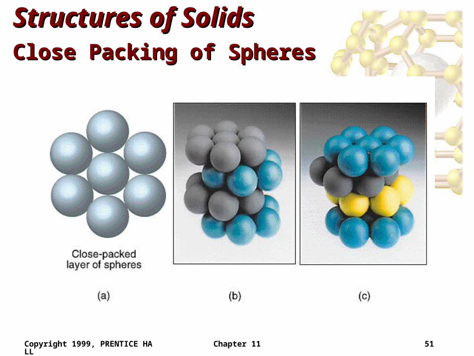
Structures of SolidsStructures of SolidsClose Packing of SpheresClose Packing of Spheres• A crystal is built up by placing close packed layers of
spheres on top of each other.• There is only one place for the second layer of
spheres.• There are two choices for the third layer of spheres:
– Third layer eclipses the first (ABAB arrangement). This is called hexagonal close packing (hcp);
– Third layer is in a different position relative to the first (ABCABC arrangement). This is called cubic close packing (ccp).
Copyright 1999, PRENTICE HALL Chapter 11 51
Structures of SolidsStructures of SolidsClose Packing of SpheresClose Packing of Spheres
Copyright 1999, PRENTICE HALL Chapter 11 52
Structures of SolidsStructures of SolidsClose Packing of SpheresClose Packing of Spheres• Each sphere is surrounded by 12 other spheres (6 in
one plane, 3 above and 3 below).• Coordination number: the number of spheres directly
surrounding a central sphere.• Hexagonal and cubic close packing are different from
the cubic unit cells.• If unequally sized spheres are used, the smaller
spheres are placed in the interstitial holes.
Copyright 1999, PRENTICE HALL Chapter 11 53
Structures of SolidsStructures of SolidsX-Ray DiffractionX-Ray Diffraction• When waves are passed through a narrow slit they
are diffracted.• When waves are passed through a diffraction grating
(many narrow slits in parallel) they interact to form a diffraction pattern (areas of light and dark bands).
• Efficient diffraction occurs when the wavelength of light is close to the size of the slits.
• The spacing between layers in a crystal is 2 - 20 Å, which is the wavelength range for X-rays.
Copyright 1999, PRENTICE HALL Chapter 11 54
Structures of SolidsStructures of SolidsX-Ray DiffractionX-Ray Diffraction
Copyright 1999, PRENTICE HALL Chapter 11 55
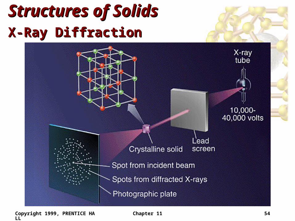
Structures of SolidsStructures of SolidsX-Ray DiffractionX-Ray Diffraction• X-ray diffraction (X-ray crystallography):
– X-rays are passed through the crystal and are detected on a photographic plate.
– The photographic plate has one bright spot at the center (incident beam) as well as a diffraction pattern.
– Each close packing arrangement produces a different diffraction pattern.
– Knowing the diffraction pattern, we can calculate the positions of the atoms required to produce that pattern.
– We calculate the crystal structure based on a knowledge of the diffraction pattern.
Copyright 1999, PRENTICE HALL Chapter 11 56
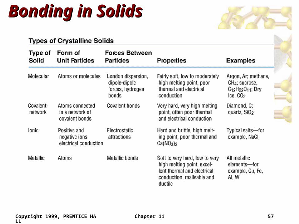
Bonding in SolidsBonding in Solids
• There are four types of solid:– Molecular (formed from molecules) - usually soft with low
melting points and poor conductivity.
– Covalent network (formed from atoms) - very hard with very high melting points and poor conductivity.
– Ions (formed form ions) - hard, brittle, high melting points and poor conductivity.
– Metallic (formed from metal atoms) - soft or hard, high melting points, good conductivity, malleable and ductile.
Copyright 1999, PRENTICE HALL Chapter 11 57
Bonding in SolidsBonding in Solids
Copyright 1999, PRENTICE HALL Chapter 11 58
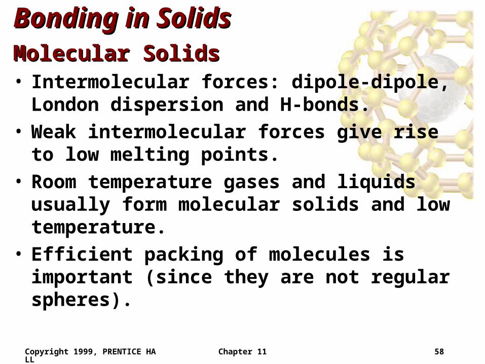
Bonding in SolidsBonding in SolidsMolecular SolidsMolecular Solids• Intermolecular forces: dipole-dipole, London
dispersion and H-bonds.• Weak intermolecular forces give rise to low melting
points.• Room temperature gases and liquids usually form
molecular solids and low temperature.• Efficient packing of molecules is important (since they
are not regular spheres).
Copyright 1999, PRENTICE HALL Chapter 11 59
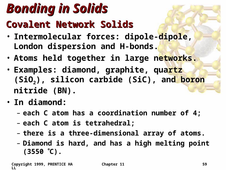
Bonding in SolidsBonding in SolidsCovalent Network SolidsCovalent Network Solids• Intermolecular forces: dipole-dipole, London
dispersion and H-bonds.• Atoms held together in large networks.
• Examples: diamond, graphite, quartz (SiO2), silicon carbide (SiC), and boron nitride (BN).
• In diamond: – each C atom has a coordination number of 4;
– each C atom is tetrahedral;
– there is a three-dimensional array of atoms.
– Diamond is hard, and has a high melting point (3550 C).
Copyright 1999, PRENTICE HALL Chapter 11 60
Bonding in SolidsBonding in SolidsCovalent Network SolidsCovalent Network Solids
Copyright 1999, PRENTICE HALL Chapter 11 61
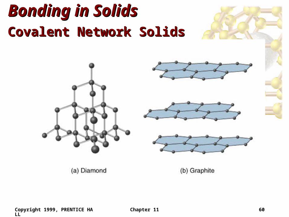
Bonding in SolidsBonding in SolidsCovalent Network SolidsCovalent Network Solids• In graphite
– each C atom is arranged in a planar hexagonal ring;
– layers of interconnected rings are placed on top of each other;
– the distance between C atoms is close to benzene (1.42 Å vs. 1.395 Å in benzene);
– the distance between layers is large (3.41 Å);
– electrons move in delocalized orbitals (good conductor).
Copyright 1999, PRENTICE HALL Chapter 11 62
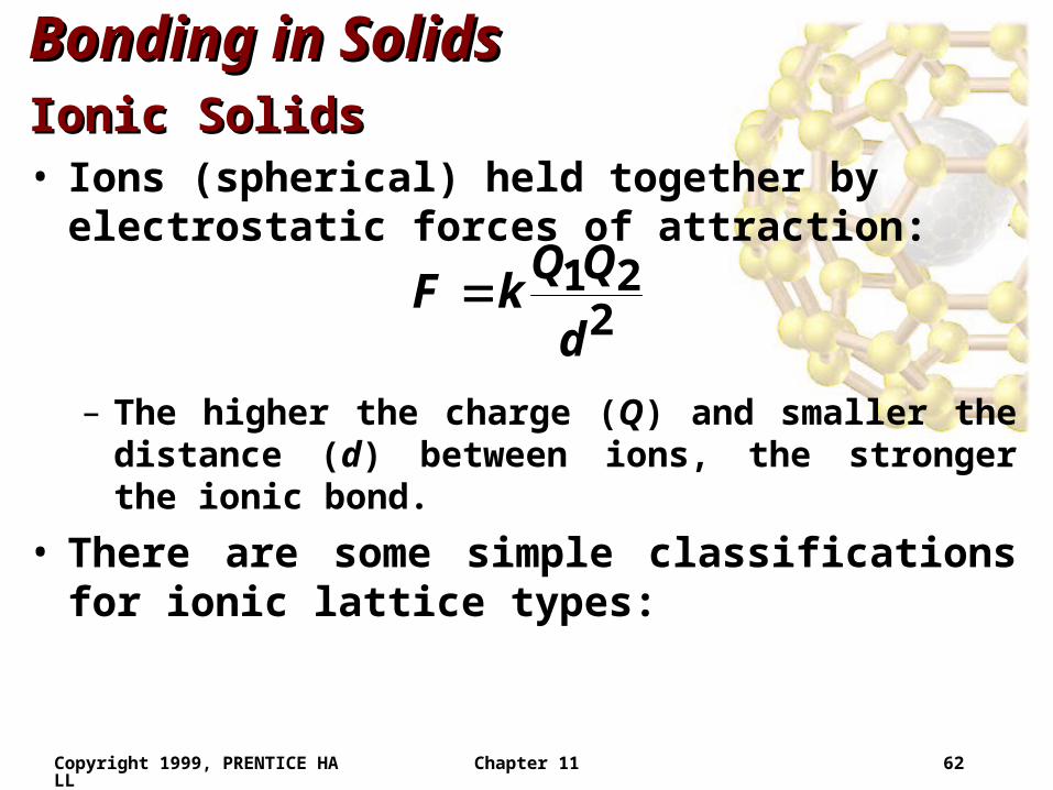
Bonding in SolidsBonding in SolidsIonic SolidsIonic Solids• Ions (spherical) held together by electrostatic forces of
attraction:
– The higher the charge (Q) and smaller the distance (d) between ions, the stronger the ionic bond.
• There are some simple classifications for ionic lattice types:
221
d
QQkF
Copyright 1999, PRENTICE HALL Chapter 11 63
Bonding in SolidsBonding in SolidsIonic SolidsIonic Solids
Copyright 1999, PRENTICE HALL Chapter 11 64
Bonding in SolidsBonding in Solids
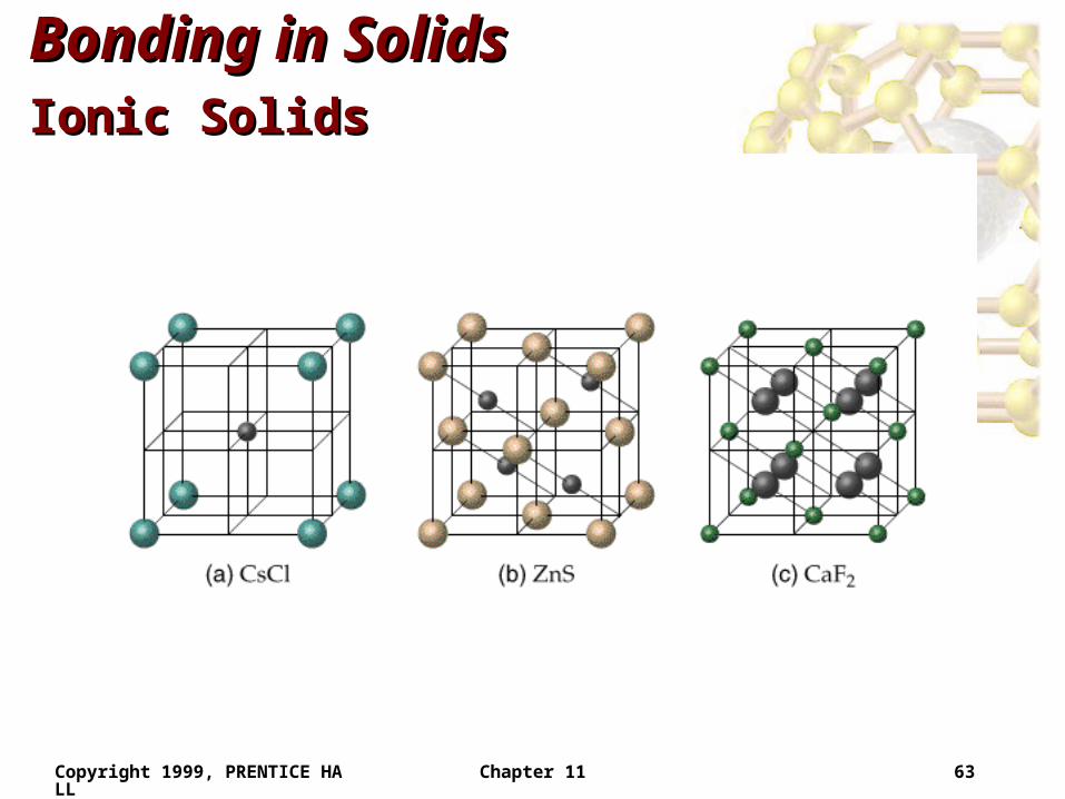
Ionic SolidsIonic Solids– NaCl Structure
• Each ion has a coordination number of 6.
• Face-centered cubic lattice.
• Cation to anion ratio is 1:1.
• Examples: LiF, KCl, AgCl and CaO.
– CsCl Structure• Cs+ has a coordination number of 8.
• Different from the NaCl structure (Cs+ is larger than Na+).
• Cation to anion ratio is 1:1.
Copyright 1999, PRENTICE HALL Chapter 11 65
Bonding in SolidsBonding in SolidsIonic SolidsIonic Solids
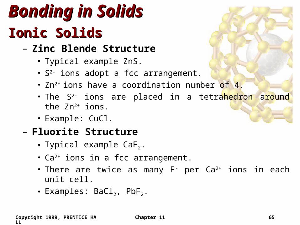
– Zinc Blende Structure• Typical example ZnS.
• S2- ions adopt a fcc arrangement.
• Zn2+ ions have a coordination number of 4.
• The S2- ions are placed in a tetrahedron around the Zn2+ ions.
• Example: CuCl.
– Fluorite Structure• Typical example CaF2.
• Ca2+ ions in a fcc arrangement.
• There are twice as many F- per Ca2+ ions in each unit cell.
• Examples: BaCl2, PbF2.
Copyright 1999, PRENTICE HALL Chapter 11 66
Bonding in SolidsBonding in Solids
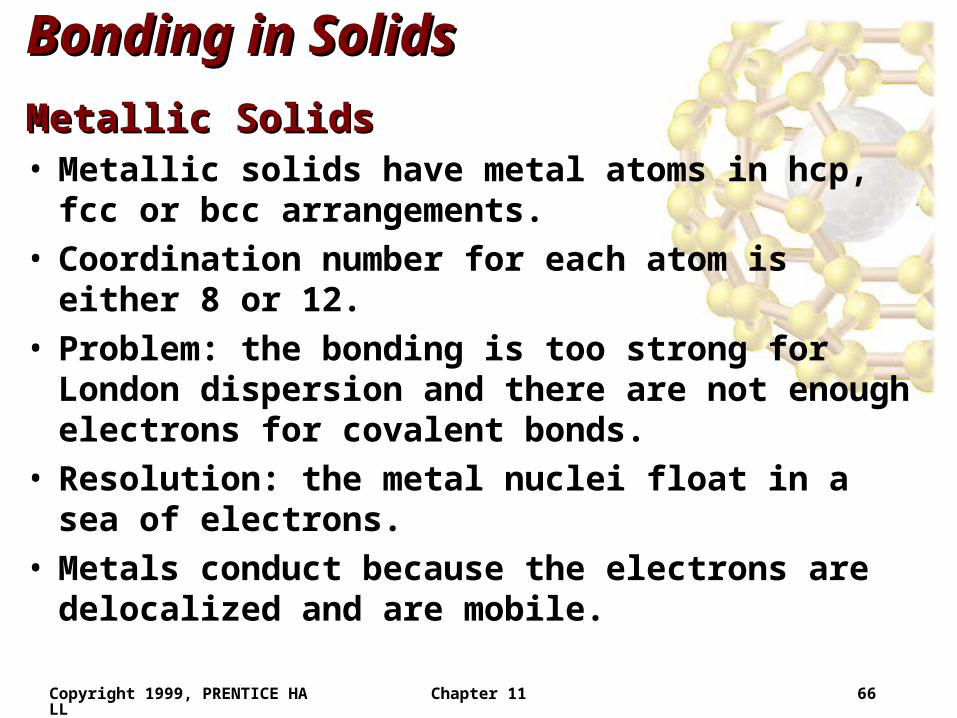
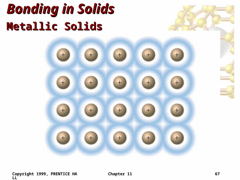
Metallic SolidsMetallic Solids• Metallic solids have metal atoms in hcp, fcc or bcc
arrangements.• Coordination number for each atom is either 8 or 12.• Problem: the bonding is too strong for London
dispersion and there are not enough electrons for covalent bonds.
• Resolution: the metal nuclei float in a sea of electrons.• Metals conduct because the electrons are delocalized
and are mobile.
Copyright 1999, PRENTICE HALL Chapter 11 67
Bonding in SolidsBonding in SolidsMetallic SolidsMetallic Solids
Copyright 1999, PRENTICE HALL Chapter 11 68
End of Chapter 11End of Chapter 11
Intermolecular Forces, Intermolecular Forces, Liquids, and SolidsLiquids, and Solids