Embed Size (px)
Citation preview
Copyright © 2009 Pearson Education, Inc.
Admin:
• Register for MasteringPhysics• www.masteringphysics.com• Course ID: MPHOLDER67874• 121/132 Registered
• First graded assignment is posted.• Due Monday 23rd
• Assignments make up 20% of your grade• Late assignments receive a 25% penalty (unless
you get an approved extension from me)

Copyright © 2009 Pearson Education, Inc.
Today• Meters• More on sources
Copyright © 2009 Pearson Education, Inc.
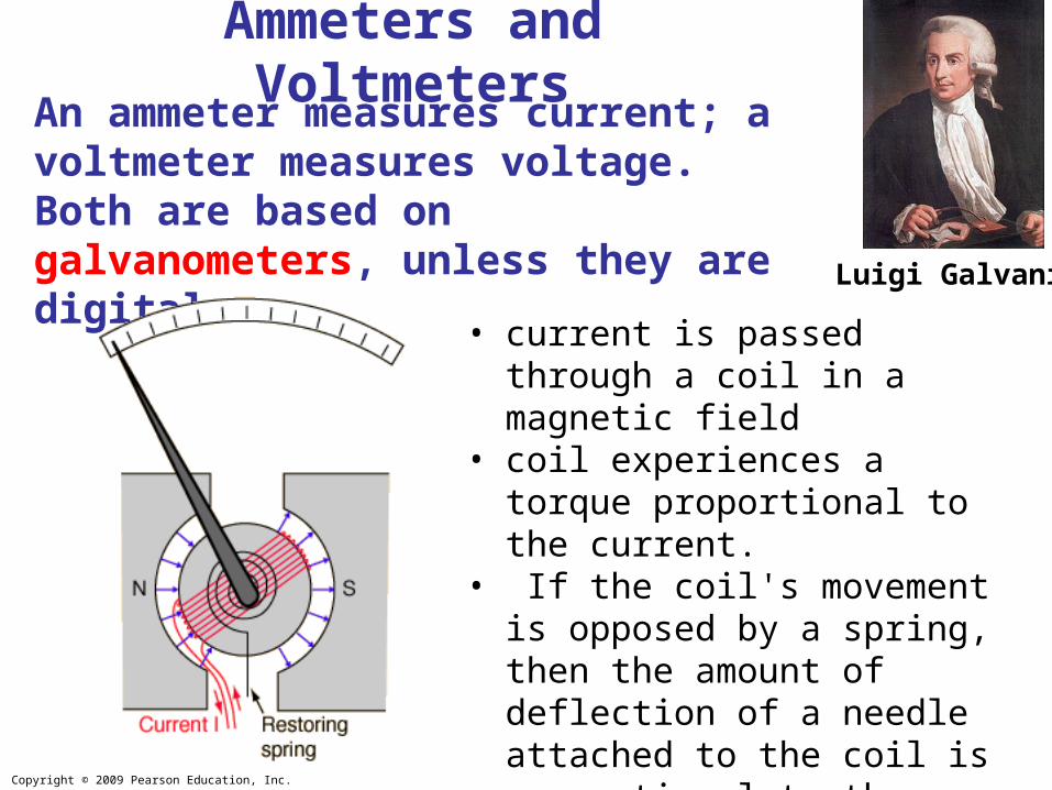
An ammeter measures current; a voltmeter measures voltage. Both are based on galvanometers, unless they are digital.
Ammeters and Voltmeters
• current is passed through a coil in a magnetic field
• coil experiences a torque proportional to the current.
• If the coil's movement is opposed by a spring, then the amount of deflection of a needle attached to the coil is proportional to the current passing through the coil.
Luigi Galvani
Copyright © 2009 Pearson Education, Inc.
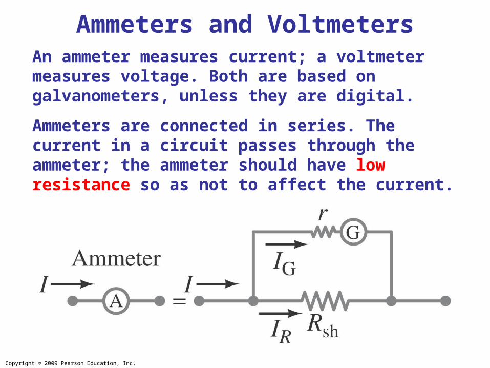
An ammeter measures current; a voltmeter measures voltage. Both are based on galvanometers, unless they are digital.
Ammeters are connected in series. The current in a circuit passes through the ammeter; the ammeter should have low resistance so as not to affect the current.
Ammeters and Voltmeters
Copyright © 2009 Pearson Education, Inc.
Ammeters and Voltmeters
Example: Ammeter design.
Design an ammeter to read 1.0 A at full scale using a galvanometer with a full-scale sensitivity of 50 μA and a resistance r = 30 Ω.
Copyright © 2009 Pearson Education, Inc.
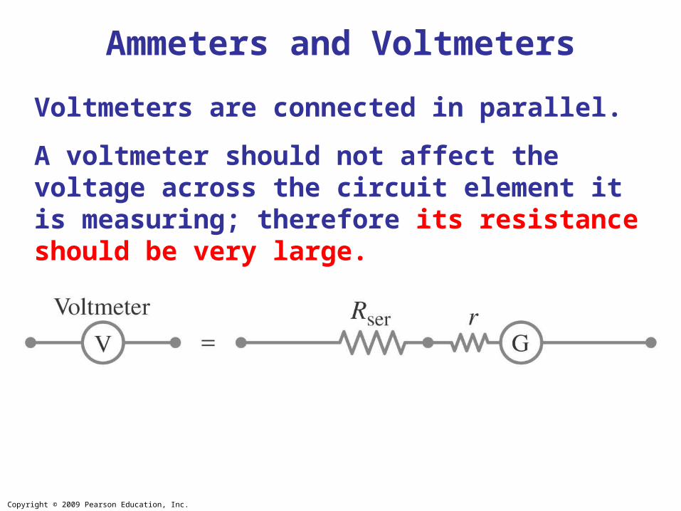
Voltmeters are connected in parallel.
A voltmeter should not affect the voltage across the circuit element it is measuring; therefore its resistance should be very large.
Ammeters and Voltmeters
Copyright © 2009 Pearson Education, Inc.
Ammeters and Voltmeters
Example : Voltmeter design.
Using a galvanometer with internal resistance 30 Ω and full-scale current sensitivity of 50 μA, design a voltmeter that reads from 0 to 15 V.
Copyright © 2009 Pearson Education, Inc.
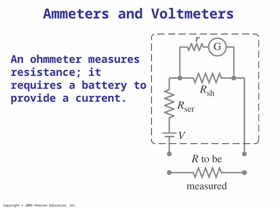
An ohmmeter measures resistance; it requires a battery to provide a current.
Ammeters and Voltmeters
Copyright © 2009 Pearson Education, Inc.
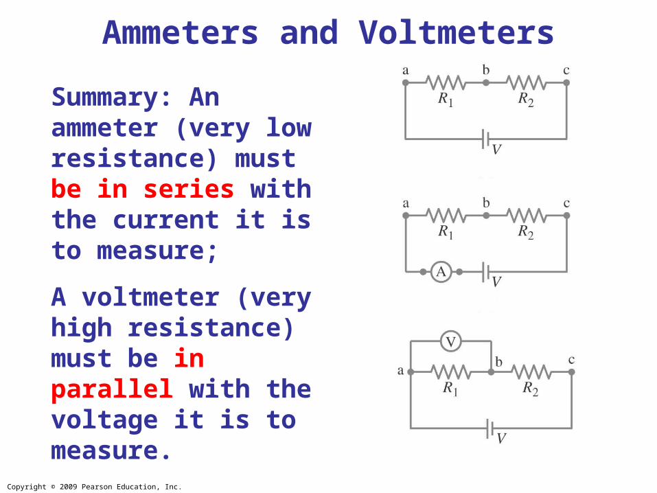
Summary: An ammeter (very low resistance) must be in series with the current it is to measure;
A voltmeter (very high resistance) must be in parallel with the voltage it is to measure.
Ammeters and Voltmeters
Copyright © 2009 Pearson Education, Inc.
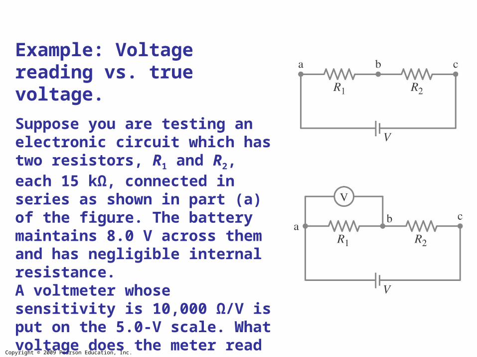
Example: Voltage reading vs. true voltage.
Suppose you are testing an electronic circuit which has two resistors, R1 and R2, each 15 kΩ, connected in series as shown in part (a) of the figure. The battery maintains 8.0 V across them and has negligible internal resistance. A voltmeter whose sensitivity is 10,000 Ω/V is put on the 5.0-V scale. What voltage does the meter read when connected across R1, and what error is caused by the finite resistance of the meter?

Copyright © 2009 Pearson Education, Inc.
More on Sources• Sources and Loads
– Source + load = simplest description of any electrical system– Voltage sources and current sources – provide prescribed voltages / currents– Ideal sources: can provide any amount of energy– In the ideal case, Voltage / Current values are not affected by load
– Ideal voltage source: • Output voltage does not change with current• Current supplied is determined by load• Zero internal resistance
– Ideal current source:• Output current does not change with voltage• Voltage generated is determined by load• Infinite internal resistance
battery
Copyright © 2009 Pearson Education, Inc.
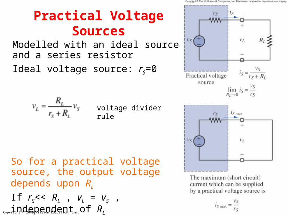
Practical Voltage Sources
Modelled with an ideal source and a series resistor
Ideal voltage source: rS=0
So for a practical voltage source, the output voltage depends upon RLIf rS<< RL , vL = vS , independent of RL
voltage dividerrule
Copyright © 2009 Pearson Education, Inc.
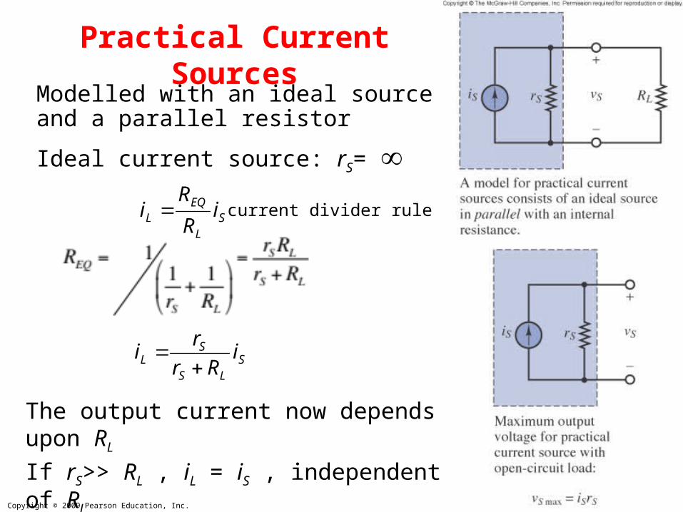
Practical Current SourcesModelled with an ideal source and a parallel resistor
Ideal current source: rS=
The output current now depends upon RLIf rS>> RL , iL = iS , independent of RL
SL
EQL i
R
Ri
SLS
SL i
Rr
ri
current divider rule