Embed Size (px)
Citation preview

Copyright © 2011 by Denny Lin 1
Computer Music Synthesis
Chapter 6Based on “Excerpt from Designing Sound”
by Andy FarnellSlides by Denny Lin
Copyright © 2011 by Denny Lin 2
Shaping sound
• 6.1 Amplitude dependent signal shaping
• 6.2 Periodic functions
• 6.3 Other functions
• 6.4 Time dependent signal shaping
Copyright © 2011 by Denny Lin 3
6.1 Amplitude dependent signal shaping
• Arithmetic is used to scale, shift, and invert signals
• Addition and multiplication are commutative
• Subtraction and division are not commutative
• It is better to multiply by decimal fractions and reserve divide for processing variable signals
Copyright © 2011 by Denny Lin 4
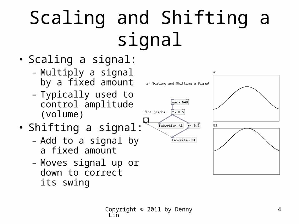
Scaling and Shifting a signal
• Scaling a signal:– Multiply a signal by a
fixed amount– Typically used to
control amplitude (volume)
• Shifting a signal:– Add to a signal by a
fixed amount– Moves signal up or
down to correct its swing

Copyright © 2011 by Denny Lin 5
Inverting and Complementing a Signal
• Inverting a signal:– Multiply by -1– Changes phase by 180
degrees ()
• Complementing a signal:– Given signal a, its
complement is 1 – a– Has same direction as
signal inverse, but its signal polarity is retained, and defined between 0.0 and 1.0
Copyright © 2011 by Denny Lin 6
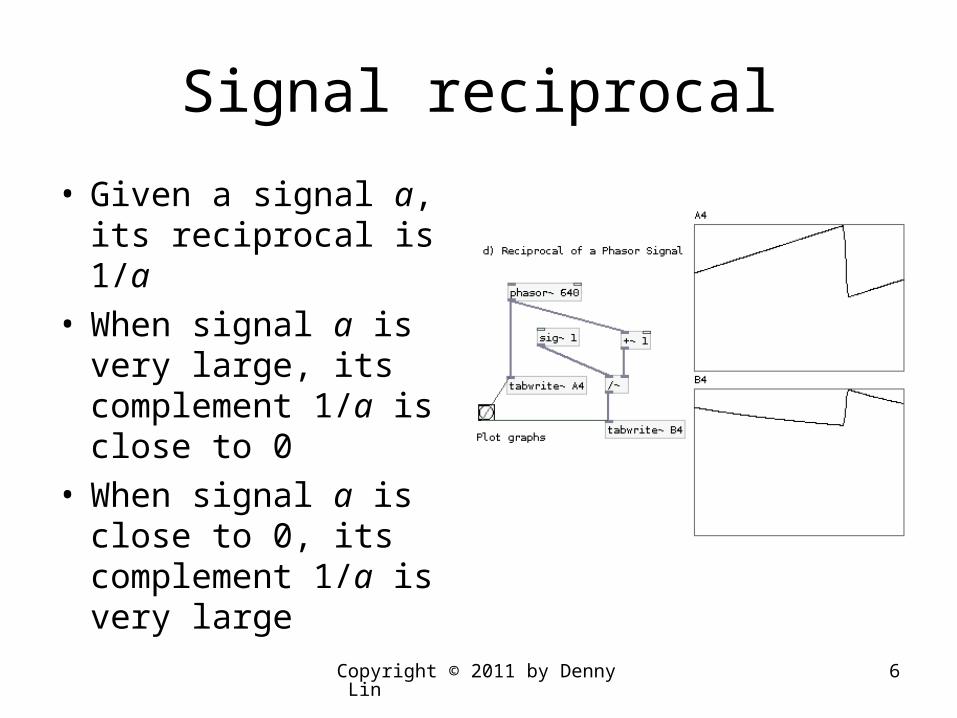
Signal reciprocal
• Given a signal a, its reciprocal is 1/a
• When signal a is very large, its complement 1/a is close to 0
• When signal a is close to 0, its complement 1/a is very large
Copyright © 2011 by Denny Lin 7
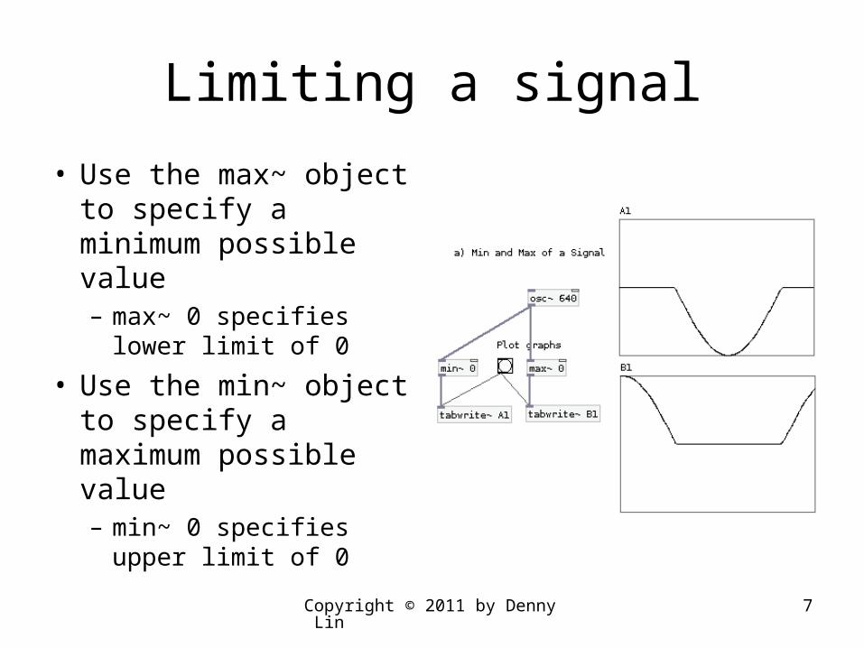
Limiting a signal
• Use the max~ object to specify a minimum possible value– max~ 0 specifies lower
limit of 0
• Use the min~ object to specify a maximum possible value– min~ 0 specifies upper
limit of 0

Copyright © 2011 by Denny Lin 8
Wave Shaping and Clipping
• A phasor can be shaped into any other waveform
• A cosine waveform can be easily shaped into a square wave
• Use the clip~ object to limit the output within a specified range
Copyright © 2011 by Denny Lin 9
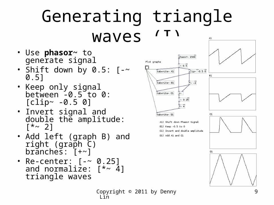
Generating triangle waves (I)
• Use phasor~ to generate signal
• Shift down by 0.5: [-~ 0.5]• Keep only signal between
-0.5 to 0: [clip~ -0.5 0]• Invert signal and double
the amplitude: [*~ 2]• Add left (graph B) and
right (graph C) branches: [+~]
• Re-center: [-~ 0.25] and normalize: [*~ 4] triangle waves
Copyright © 2011 by Denny Lin 10
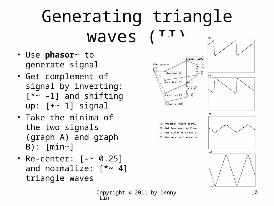
Generating triangle waves (II)
• Use phasor~ to generate signal
• Get complement of signal by inverting: [*~ -1] and shifting up: [+~ 1] signal
• Take the minima of the two signals (graph A) and graph B): [min~]
• Re-center: [-~ 0.25] and normalize: [*~ 4] triangle waves
Copyright © 2011 by Denny Lin 11
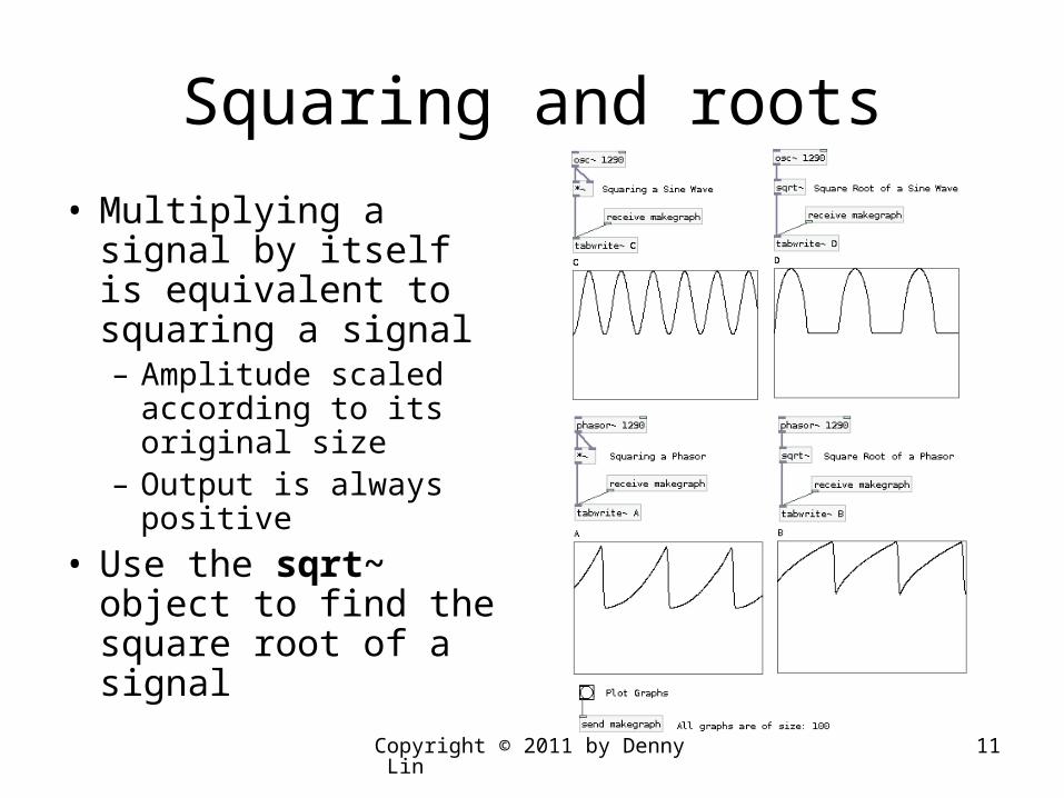
Squaring and roots
• Multiplying a signal by itself is equivalent to squaring a signal– Amplitude scaled
according to its original size
– Output is always positive
• Use the sqrt~ object to find the square root of a signal
Copyright © 2011 by Denny Lin 12
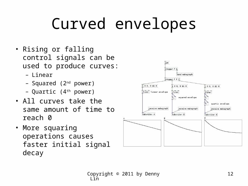
Curved envelopes
• Rising or falling control signals can be used to produce curves:– Linear– Squared (2nd power)– Quartic (4th power)
• All curves take the same amount of time to reach 0
• More squaring operations causes faster initial signal decay
Copyright © 2011 by Denny Lin 13
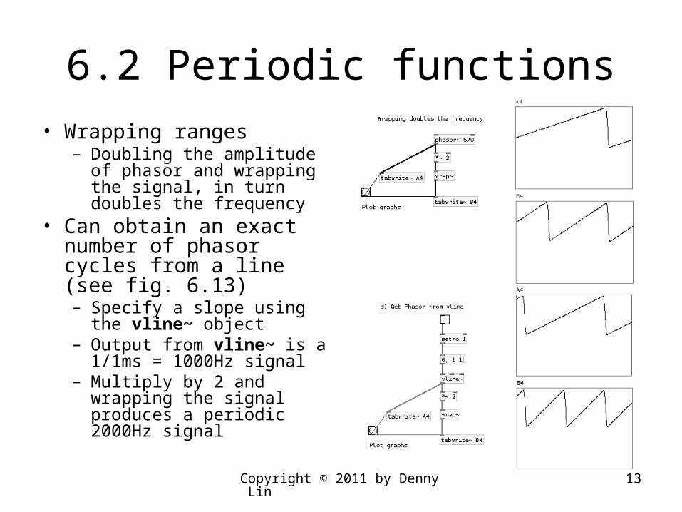
6.2 Periodic functions
• Wrapping ranges– Doubling the amplitude of
phasor and wrapping the signal, in turn doubles the frequency
• Can obtain an exact number of phasor cycles from a line (see fig. 6.13)– Specify a slope using the vline~ object
– Output from vline~ is a 1/1ms = 1000Hz signal
– Multiply by 2 and wrapping the signal produces a periodic 2000Hz signal
Copyright © 2011 by Denny Lin 14
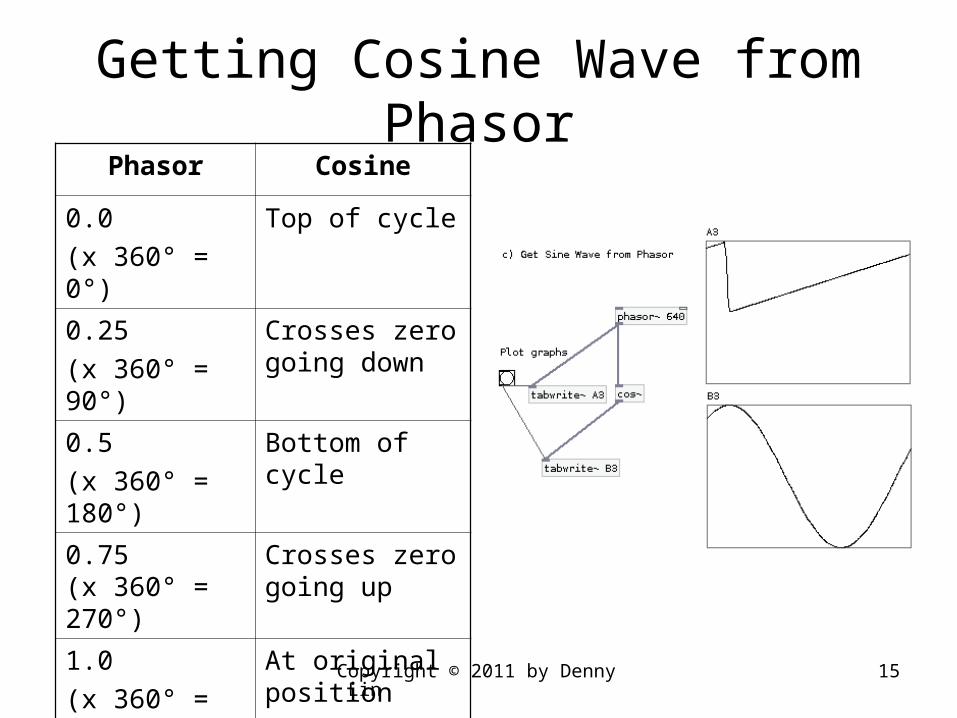
Cosine function
• A cosine oscillator can be derived from a phasor~ object
• The phasor~ object always produces a uni-polar signal in the range 0.0 to 1.0
• The cos~ object produces a bipolar waveform in the range -1.0 to 1.0
Copyright © 2011 by Denny Lin 15
Getting Cosine Wave from PhasorPhasor Cosine
0.0
(x 360° = 0°)
Top of cycle
0.25
(x 360° = 90°)
Crosses zero going down
0.5
(x 360° = 180°)
Bottom of cycle
0.75(x 360° = 270°)
Crosses zero going up
1.0
(x 360° = 360°)
At original position
Copyright © 2011 by Denny Lin 16
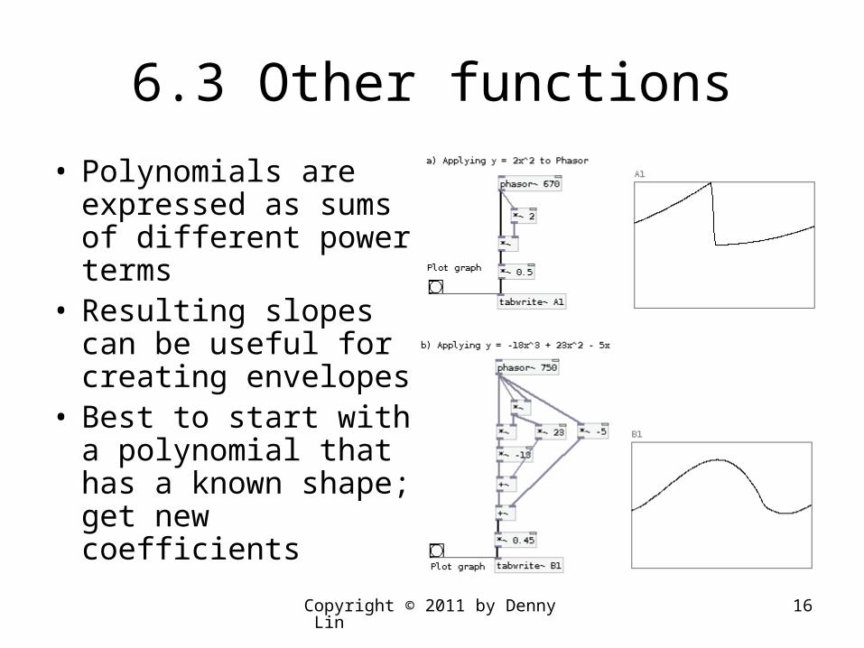
6.3 Other functions
• Polynomials are expressed as sums of different power terms
• Resulting slopes can be useful for creating envelopes
• Best to start with a polynomial that has a known shape; get new coefficients
Copyright © 2011 by Denny Lin 17
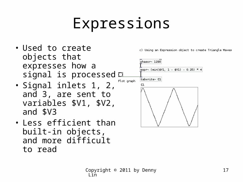
Expressions
• Used to create objects that expresses how a signal is processed
• Signal inlets 1, 2, and 3, are sent to variables $V1, $V2, and $V3
• Less efficient than built-in objects, and more difficult to read

Copyright © 2011 by Denny Lin 18
6.4 Time dependent signal shaping
• Delay
• Phase cancellation
• Filters– User friendly filters– Integration– Differentiation
Copyright © 2011 by Denny Lin 19
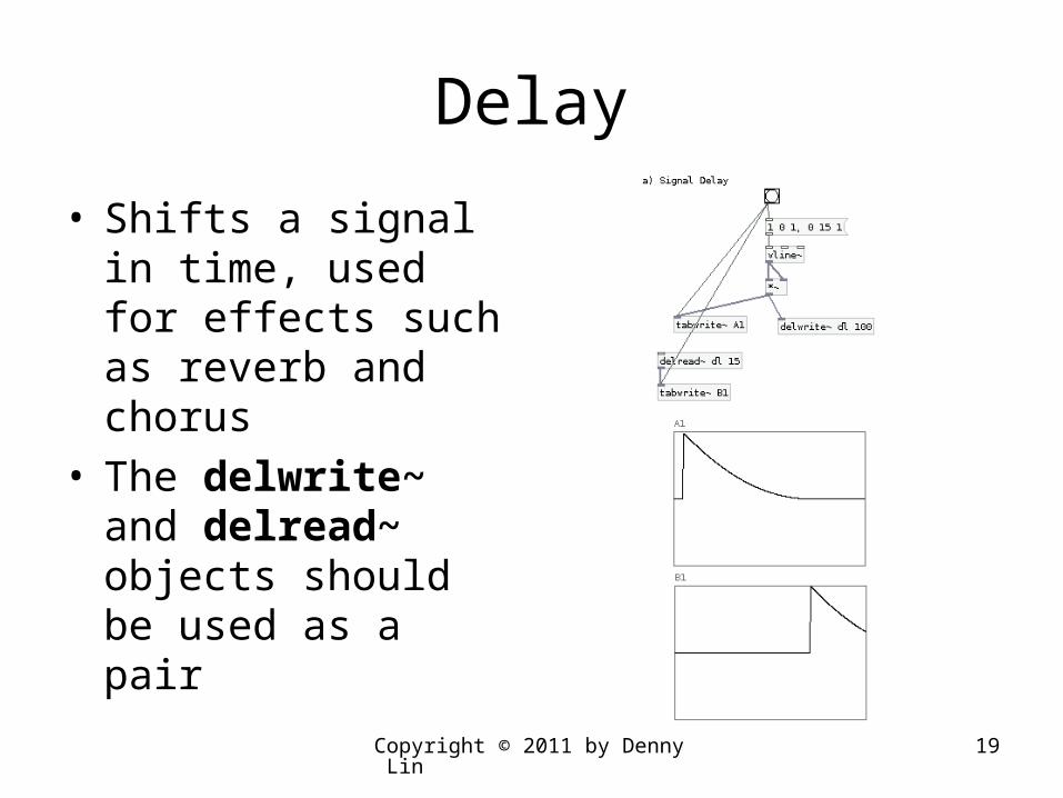
Delay
• Shifts a signal in time, used for effects such as reverb and chorus
• The delwrite~ and delread~ objects should be used as a pair

Copyright © 2011 by Denny Lin 20
Phase cancellation• Can use a delay to create a signal
that is 180 degrees out of phase (anti-phase signal) with respect to the original signal
• Mixing the original with the anti-phase signals, causes phase cancellation, so output is 0
• When the two signals are in phase, the output is 2 times the original signal
• Output amplitude may depend on the delay (given a fixed frequency), or the frequency (given a fixed delay)
• Controlling this effect is equivalent to filtering the signal
Copyright © 2011 by Denny Lin 21
Filters
• When the amplitude is reinforced by the coincidence of signal delay and period, a pole is formed
• When the delay time is half the period causing phase cancellation, a zero is formed
• Filters can be created by controlling which frequencies are amplified and which are cancelled

Copyright © 2011 by Denny Lin 22
The rpole~ object
• Low-pass filters an audio signal fed to its left inlet; can act as an integrator
• Recursive filter• The first argument or audio signal fed to its right
inlet, defines the real-valued filter co-efficient a[n] in:
• y[n] = y[n-1] + a[n] * x[n]– where y[n] is the output– x[n] is the input– Filter is not stable when |a[n]| > 1
Copyright © 2011 by Denny Lin 23
The rzero~ object
• High-pass filters an audio signal fed to its left inlet; can act as a differentiator
• Non-recursive filter• The first argument or audio signal fed to its right
inlet, defines the real-valued filter co-efficient a[n] in:
• y[n] = x[n] - a[n] * x[n-1]– where y[n] is the output– x[n] is the input– Filter is always stable
Copyright © 2011 by Denny Lin 24
User-Friendly Filters
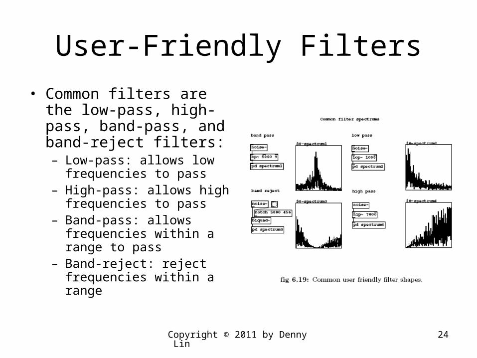
• Common filters are the low-pass, high-pass, band-pass, and band-reject filters:– Low-pass: allows low
frequencies to pass– High-pass: allows high
frequencies to pass– Band-pass: allows
frequencies within a range to pass
– Band-reject: reject frequencies within a range
Copyright © 2011 by Denny Lin 25
Integration
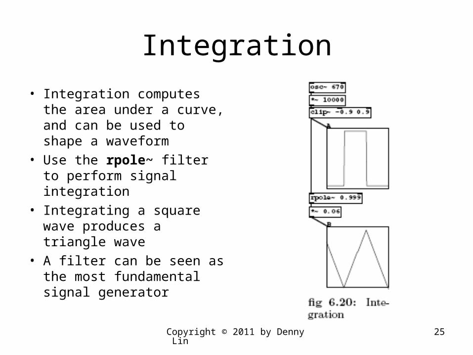
• Integration computes the area under a curve, and can be used to shape a waveform
• Use the rpole~ filter to perform signal integration
• Integrating a square wave produces a triangle wave
• A filter can be seen as the most fundamental signal generator
Copyright © 2011 by Denny Lin 26
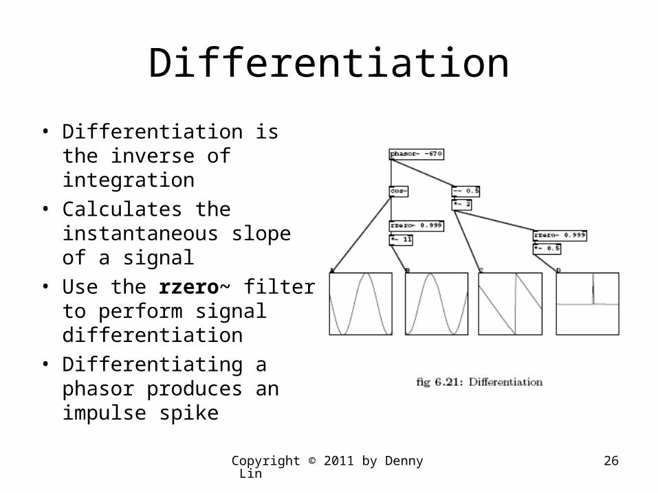
Differentiation
• Differentiation is the inverse of integration
• Calculates the instantaneous slope of a signal
• Use the rzero~ filter to perform signal differentiation
• Differentiating a phasor produces an impulse spike