Embed Size (px)
Citation preview

COPYRIGHT American Society of Mechanical EngineersLicensed by Information Handling ServicesCOPYRIGHT American Society of Mechanical EngineersLicensed by Information Handling Services

A N
ASME B16.1-2001
A M E R I C A N N A T I O N A L S T A N D A R D
FACTORY-PA ADE WROUGHT
BUTTWELDINC FITTINGS
COPYRIGHT American Society of Mechanical EngineersLicensed by Information Handling ServicesCOPYRIGHT American Society of Mechanical EngineersLicensed by Information Handling Services

Date of Issuance: June 22, 2001
This Standard will be revised when the Society approves the issuance of a new edition. There will be no addenda issued to this edition. The next edition of this Standard is scheduled for publication in 2005.
ASME will issue written replies to inquiries concerning interpretation of technical aspects of this Standard.
'. .. r .
- , . . .
..' . .:. . :. _.
ASME is the registered trademark of The American Society of Mechanical Engineers.
This code or standard was developed under procedures accredited as meeting the criteria for American National Standards. The Standards Committee that approved the code or standard was balanced to assure that individuais from competent and concerned interests have had an opportunity to participate. The proposed code or standard was made available for public review and comment that provides an Opportunity for additional public input from industry, academia, regulatory agencies, and the public-at-large.
ASME does not "approve," "rate," or "endorse" any item, construction, proprietary device, or activity.
ASME does not take any position with respect to the validity of any patent rights asserted in connection with any items mentioned in this document, and does not undertake to insure anyone utilizing a standard against liability for infringement of any applicable letters patent, nor assume any such liability, Users of a code or standard are expressly advised that determination of the validity of any such patent rights, and the risk of infringement of such rights, is entirely their own responsibility.
Participation by federal agency representative(s) or person(s) affiliated with industry is not t o be interpreted as government or industry endorsement of this code or standard.
ASME accepts responsibility for only those interpretations of this document issued in accordance with the established ASME procedures and policies, which precludes the issuance of interpretations by individuals.
\
No part of this document may be reproduced in any form, in an electronic retrieval system or otherwise,
without the prior written permission of the publisher.
The American Society of Mechanical Engineers Three Park Avenue, New York, NY 10016-5990
Copyright O 2001 by THE AMERICAN SOCIETY OF MECHANICAL ENGINEERS
All Rights Reserved Printed in U.S.A.
COPYRIGHT American Society of Mechanical EngineersLicensed by Information Handling ServicesCOPYRIGHT American Society of Mechanical EngineersLicensed by Information Handling Services

FOREWORD
In 1921, the American Engineering Standards Committee, later American Standards Association (ASA), organized Sectional Committee B 16 to unify and further develop national standards for pipe flanges and fittings (and, later, for valves, gaskets, and valve actuators). Cosponsors of the B16 Committee were the American Society of Mechanical Engineers (ASME), the Heating and Piping Contractors National Association [now the Mechanical Contractors Association of America (MCAA)], and the Manufacturers Standardization Society of the Valve and Fittings Industry (MSS). Cosponsors were later designated as cosecretariat organizations.
Standardization of welding fittings was initiated in 1937 by a subgroup (designated Subgroup 6) of Subcommittee 3. After consideration of several drafts, a standard was approved by the Committee, cosponsors, and ASA, and published with the designation ASA
Revisions were made in 1950 and 1955 to add sizes up to NPS 24 and to complete coverage of fittings in some sizes. These revisions were approved and published as ASA B16.9-1951 and ASA B16.9-1958. With the subgroup now designated Subcommittee 6 (later Subcommittee F), further revisions were begun to clarify the intent of the standard, to add angularity tolerances, and to include fittings of different types (long radius-reducing elbows and crosses) and smaller sizes (NPS v4 and %). This revision was published as ASA B16.9- 1964 after ASA approval.
After reorganization of ASA, first as the United States of America Standards Institute (USASI), then as the American National Standards Institute (ANSI), with the Sectional Committee being redesignated as an American National Standards Committee, another revision increasing the size range to NPS 48 and revising the text for clarity was approved and published as ANSI B16.9-1971.
In 1975, Subcommittee F began a major revision to bring the standard up to date with current practice and usage. Common fractions were expressed as decimals (but without intending higher precision) and metric dimensional equivalents were added. Provisions for step-wise change of radius for NPS q4 long radius elbows and 180 deg returns were introduced. Following Standards Committee, cosecretariat, and ANSI approval, the revision was published as ANSI B16.9-1978. It was updated by a corrective addendum, B16.9a- 1981, issued in February 1982.
In 1982, American National Standards Committee B16 was reorganized as an ASME Committee operating under procedures accredited by ANSI. In this Edition, the text has been revised and inch dimensions are established as the standard. Following approval by the Standards Committee and ASME, approval as an American National Standard was given by ANSI on November 12, 1986 with the new designation ASME/ANSI B16.9-1986.
In 1991 the Subcommittee reviewed the document and made a number of revisions. Dimensions for short pattern lap joints were also added to this 1993 Edition of the Standard.
In this 2001 Edition, short radius elbows and returns were added which includes all dimensions and tolerances of ASME B 16.28-1994. This Edition also provides metric units as an independent but parallel alternative standard to U.S. Customary units and a Quality System Program Annex.
B 16.9- 1940.
... 111
COPYRIGHT American Society of Mechanical EngineersLicensed by Information Handling ServicesCOPYRIGHT American Society of Mechanical EngineersLicensed by Information Handling Services

Requests for interpretation or suggestions for revision should be sent to the Secretary, B16 Committee, The American Society of Mechanical Engineers, Three Park Avenue, New York, NY 10016.
This Standard was approved as an American National Standard on April 6, 2001.
iv
COPYRIGHT American Society of Mechanical EngineersLicensed by Information Handling ServicesCOPYRIGHT American Society of Mechanical EngineersLicensed by Information Handling Services

ASME STANDARDS COMMIlTEE BI6 Standardization of Valves, Flanges, Fittings, and
Gaskets
(The following is the roster of the Committee at the time of approval of this Standard.)
OFFICERS
W. N. McLean, Chair H. R. Sonderegger, Vice Chair
P. Reddington, Secretary
COMMITIEE PERSONNEL
W. L. Ballis, Columbia Gas Distribution Co. J. E. Betey, Union Carbide Corp. K. M. Bell, Underwriter's Laboratory, Inc. M. L. Blair, US. Coast Guard R. R. Brodin, Fisher Controls International, Inc. A. Cohen, Copper Development Association W. C. Farrell, Jr., Consultant C. E. Floren, Mueller Co. D. R. Frikken, Monsanto Co. M. W. Garland, Frick Co. J. B. Hagen, ABS Americas J. C. Inch, Mueller Brass Co. J. S. John, J Square Engineering Co. G. A. Jolly, Vogt Valve Co. W. G. Knecht, AnchorDarling Valve Co. R. Koester, The William Powell Co. J. H. Longacre, Nibco, Inc. J. H. McCauley, Jr., James H. McCauley, Inc. W. N. Mclean, Newco Valves A. F. Rhodes, Arnco Technology Trust F. C. Rosch. Jr., Techincon Enterprises, Inc. R. A. Schmidt, Ladish Co. H. R. Sonderegger, Tyco Flow Control W. M. Stephan, Flexitallic Inc. T. F. Stroud, Ductile Iron Pipe Research Association R. E. White, Repairs, Inc. D. A. Williams, Southern Company Services L. A. Willis, Dow Chemical Co.
SUBCOMMITTEE F - STEEL THREADED AND WELDING FITTINGS
G. A. Jolly, Chairman, Vogt Valve Co. S. J. Rossi, Secretary, The American Society of Mechanical Engineers P. R. Benavides, Tube Forgings of American, Inc. G. A. Cuccio, Capitol Manufacturing J. P. Elienberger, WFI International D. R. Frikken, Monsanto Co.
V
COPYRIGHT American Society of Mechanical EngineersLicensed by Information Handling ServicesCOPYRIGHT American Society of Mechanical EngineersLicensed by Information Handling Services

R. E. Johnson, Consultant R. C. Lafferty, Penna Machine Works, Inc. D. H. Monroe, Consultant R. A. Schmidt, Ladish Co. H. R. Sonderegger, Tyco Flow Control L. A. Willis, Dow Chemical Co. W. R. Worley, Union Carbide
,
vi
COPYRIGHT American Society of Mechanical EngineersLicensed by Information Handling ServicesCOPYRIGHT American Society of Mechanical EngineersLicensed by Information Handling Services

CONTENTS
... Foreword ............................................................................ 111
Committee Roster .................................................................... v
1 Scope .......................................................................... 1 1.1 General ..................................................................... 1 1.2 Special Fittings .............................................................. 1 1.3 Fabricated Fittings ........................................................... 1 1.4 Standard Units .............................................................. 1 1.5 References .................................................................. 1 1.6 Service Conditions ............................................................ 1 1.7 Welding .................................................................... 1 1.8 Quality Systems ............................................................. 1 1.9 Convention .................................................................. 1
2 Pressure Ratings .............................................................. 1 2.1 Basis of Ratings ............................................................. 1 2.2 Design of Fittings ........................................................... 2
3 Size . . . . . . . . . . . . . . . . . . . . . . . . . . . . . . . . . . . . . . . . . . . . . . . . . . . . . . . . . . . . . . . . . . . . . . . . . . . . 2
4 Marking ........................................................................ 4.1 Standard Marking ............................................................
4.3 Depth of Stamping .......................................................... 4.2 Exceptions . . . . . . . . . . . . . . . . . . . . . . . . . . . . . . . . . . . . . . . . . . . . . . . . . . . . . . . . . . . . . . . . . .
4.4 Compliance .................................................................
5 Material . . . . . . . . . . . . . . . . . . . . . . . . . . . . . . . . . . . . . . . . . . . . . . . . . . . . . . . . . . . . . . . . . . . . . . . .
6 Fitting Dimensions ............................................................ 6.1 General . . . . . . . . . . . . . . . . . . . . . . . . . . . . . . . . . . . . . . . . . . . . . . . . . . . . . . . . . . . . . . . . . . . . . 6.2 Special Dimensions . . . . . . . . . . . . . . . . . . . . . . . . . . . . . . . . . . . . . . . . . . . . . . . . . . . . . . . . . .
7 Surface Contours ...............................................................
8 End Preparation . . . . . . . . . . . . . . . . . . . . . . . . . . . . . . . . . . . . . . . . . . . . . . . . . . . . . . . . . . . . . . .
9 Design Proof Test ............................................................. 9.1 Required Tests . . . . . . . . . . . . . . . . . . . . . . . . . . . . . . . . . . . . . . . . . . . . . . . . . . . . . . . . . . . . . . 9.2 Test Assembly . . . . . . . . . . . . . . . . . . . . . . . . . . . . . . . . . . . . . . . . . . . . . . . . . . . . . . . . . . . . . . 9.3 Test Procedure .............................................................. 9.4 Applicability of Test Results .................................................
2
3 3 3
3
3
10 Production Tests . . . . . . . . . . . . . . . . . . . . . . . . . . . . . . . . . . . . . . . . . . . . . . . . . . . . . . . . . . . . . . 5
vii
COPYRIGHT American Society of Mechanical EngineersLicensed by Information Handling ServicesCOPYRIGHT American Society of Mechanical EngineersLicensed by Information Handling Services
11 Tolerances . . . . . . . . . . . . .. . . . . . . . . . . . . . . . . . . . . . . . . . . . . . . . . . . . . . . . . . . . . . . . . . . . . . . . 5
Figure 1 Maximum Envelope for Welding End Transitions . . .. . . . . . . . . . . . . . . . . . .. . . . . . .. 5
Tables 1 Welding Bevels and Root Face ... . ,. . .. .. . .. ... .. . .. .. . . . . .. . .. . . . . . . . . . . . . . . . . . . 2 Tolerances . . . . . . . . . . . . . . . . . . . . . . . . . . . . . . . . . . . . . . . . . . . . . . . . . . . . . . . , . . , . . . . . . . . . . . . 3 Dimensions of Long Radius Elbows ......... . . . . . . . . . . . . . . . . . . . . . . . . . . . . . . . . . . . . . 4 Dimensions of Long Radius-Reducing Elbows ....... . . . . . . . . . . . . . . . . . . . . . . . . . . . . . . 5 Dimensions of Long Radius Returns . . .. . . . . . . . . . . . . . . . . . . . . . . . . . . . . . . . . . . . . . . . . . . 6 Dimensions of Short Radius Elbows . . . . . . . . . . . . . . . . .. . . . . . . . . . . . . . . . . . . . . . . . . . . . . 7 Dimensions of Short Radius 180 Deg Returns . ... ... .. . . .. .. . .. . . . .. . .. . .. . . . . . . . . 8 Dimensions of Straight Tees and Crosses .. .. .. . .. .. ... ... .. . .. .. . . . . . . . .. . .. . . . . . 9 Dimensions of Reducing Outlet Tees and Reducing Outlet Crosses . . . . . . . . . . . . . . . . . 10 Dimensions of Lap Joint Stub Ends .... .. . .. .. .. . .. ... ... . .. . .. . .. . . . . . . .. . . . . .. . 11 Dimensions of Caps . . . . . . . ....... .. . .. .. . .. . . . . . . . ... . .. .. . .. . . .. . .. . .. . . . . . . . . . 12 Dimensions of Reducers .... .. . .. .. ... .... . .. .. ... .. ... ... .. . . . .. ... . . . .. . . . . . . . . .
4 6 8 9
10 10 11 1 1 12 17 18 19
Mandatory Appendices I II
Nonmandatory Appendices A
Inch Tables . .. .. . . .. . .. . . . . . . . .. . . . .. ... .. . . . . . . . .. . . . . . . .. . .. .. .. . . . . . . . . . . . .. . . References . ... . . . . .. . . .... . .. ... . . . . . . . . . .. .. .. .. . . . .. ... ... .... ..,... . . . . . . . . . . .
21 35
Quality System Program . . . . . . . . . .. . .. . . .. .. . . .. . .. . .. . .. . . .. ... . .. . . . . . . . . . . . . .. . 36
... v111
COPYRIGHT American Society of Mechanical EngineersLicensed by Information Handling ServicesCOPYRIGHT American Society of Mechanical EngineersLicensed by Information Handling Services

ASME 816.9-2001
FACTORY-MADE WROUGHT BUTTWELDING FITTINGS
O
e
1 SCOPE
1.1 General
This Standard covers overall dimensions, tolerances, ratings, testing, and markings for wrought factory-made buttwelding fittings in sizes NPS ‘/2 through 48 (DN 15 through 1200).
1.2 Special Fittings
Fittings may be made to special dimensions, sizes, shapes, and tolerances by agreement between the manu- facturer and the purchaser.
1.3 Fabricated Fittings
Fabricated laterals and other fittings employing cir- cumferential or intersection welds are considered pipe fabrication, and are not within the scope of this Standard.
1.4 Standard Units
The values stated in either metric or U.S. Customary units are to be regarded separately as standard. Within the text, the U.S. Customary units are shown in parentheses. The values stated in each system are not exact equivalents; therefore, each system must be used independently of the other. Combining values from the two systems may result in nonconformance with this Standard.
The designations for pressure rating and size are Class and NPS for both metric and customary dimen- sioned fittings. The designations PN and DN used in international standards are shown for reference conve- nience.
1.5 References
1.5.1 Referenced Standards. Standards and spec- ifications adopted by reference in this Standard are shown in Mandatory Appendix II. It is not considered practical to identify the specific edition of each standard and specification in the individual references. Instead, the specific edition reference is identified in Mandatory Appendix II. A product made in conformance with a prior edition of reference standards and in all other respects conforming to this Standard will be considered to be in conformance.
1.5.2 Codes and Regulations. A fitting used under the jurisdiction of the ASME Boiler and Pressure Vessel Code, the ASME Code for Pressure Piping, or a governmental regulation is subject to any limitation of that code or regulation. This includes any maximum temperature limitation, or rule governing the use of a material at low temperature.
1.6 Service Conditions
Criteria for selection of fitting types and materials suitable for particular fluid service are not within the scope of this Standard.
1.7 Welding
Installation welding requirements are outside the scope of this Standard.
1.8 Quality Systems
Nonmandatory requirements relating to the fitting manufacturer’s Quality System Program are described in Nonmandatory Appendix A.
1.9 Convention
For the purpose of determining conformance with this Standard, the convention for fixing significant digits where limits, maximum or minimum values, are speci- fied shall be rounded off as defined in ASTM E 29. This requires that an observed or calculated value shall be “rounded off’ to the nearest unit in the last right- hand digit used in expressing the limit. Decimal value in the last and tolerances do not imply a particular method of measurement.
2 PRESSURE RATINGS
2.1 Basis of Ratings
The allowable pressure ratings for fittings designed in accordance with this Standard may be calculated as for straight seamless pipe of equivalent material (as shown by comparison of composition and mechanical properties in the respective materiai specifications) in accordance with the rules established in the applicable
1
I
COPYRIGHT American Society of Mechanical EngineersLicensed by Information Handling ServicesCOPYRIGHT American Society of Mechanical EngineersLicensed by Information Handling Services

. .
. .i.., ’ . j . .,: .::<,L.: . .. ,._ ... . ,_ . .
. .
ASME 816.9-2001 FACTORY-MADE WROUGHT BUTWELDING FIlTINGS
a (d) size - the nominal pipe size (NPS) identificatio number related to the end connections shall be used.
(e) compliance - see para 4.4 for standard and special fitting marking.
If) A manufacturer may supplement these mandatory markings with others, including a DN size designation, but confusion with the required marking shall be avoided.
. :: .:~.-..:ii- . ..
sections of ASME B31, Code for Pressure Piping. For the calculation, applicable data for the pipe size, wall thickness, and material that is equivalent to that of the fitting shall be used. Pipe size, wall thickness (or schedule number), and material identity on the fittings are in lieu of pressure rating markings.
2.2 Design of Fittings
The design of fittings shall be established by mathe- matical analyses (e.g. ASME B16.49 for bends) con- tained in nationally recognized pressure vessel or piping codes or at the manufacturer’s option by proof testing in accordance with section 9 of this Standard. In order to meet design or manufacturing requirements, it is expected that some portion of formed fittings may have to be thicker than the pipe wall with which the fittings is intended to be used. The mathematical analyses, if used, may take into account such thicker sections. Records of mathematical analysis and/or successful proof test data shall be available at the manufacturer’s facility for inspection by the purchaser.
3 SIZE
NPS, followed by a dimensionless number, is the designation for nominal fitting size. N P S is related to the reference nominal diameter, DN, used in international standards. The relationship is, typically, as follows:
DN 15 20 25 32 40 50 65 80 100
NPS ‘/2 % 1 1 % 1 % 2 292 3 4
NOTE: For NPSA, the equivalence is: DN=25 (NPS)
4 MARKING
4.1 Standard Marking
the following: Each fitting shall be permanently marked to show
(a) manufacturer’s name or trademark. (b) material identification, either the ASTM or ASME
(c) schedule number’ or nominal wall thickness in grade designation.
m.
’ Schedule number is a dimensionless number that is widely used as a convenient designation for use in ordering pipe and fittings. It is normally associated with a group of standardized pipe wall thickness. Refer to ASME B36.10 and ASME B36.19 for complete details on pipe schedule numbers.
>I
4.2 Exceptions
Where the size of the fitting does not permit complete marking, the identification &ks may be omitted in reverse of the order presented above. O 4.3 Depth of Stamping
Where steel stamps are used, care shall be taken so that the marking is not deep enough or sharp enough to cause cracks or to reduce the wall thickness of the fitting below the minimum allowed.
4.4 Compliance
4.4.1 Standard Fittings. That the fitting was man- ufactured in conformance with this Standard, including all dimensional requirements, is certified by a pre “WP” in the material grade designation marking.
’
”. 4.4.2 Special Fittings. That the fitting was manu-
factured in conformance with this Standard except that dimensional requirements are as agreed between the purchaser and the manufacturer, is certified by a supple- mentary suffix to the material grade designation marking as follows:
(a) S9 applies for fittings in accordance with ASTM A 234 and A 403.
(b) S6 applies for fittings in accordance with ASTM A 420.
(c) S8 applies for fittings in accordance with AS A 815.
(d) SPLD applies for fittings in accordance with ASTM B 361, B 363, and B 366.
5 MATERIAL
Wrought fittings covered by this Standard shall be in accordance with ASTM A 234, A 403, A 420, A 815, B 361, B 363, B 366 or the corresponding standard listed in Section II of the ASME Boiler and Pressure Vessel Code. The t e m wrought denotes fittings made of pipe, tubing, plate, or forgings. Fittings made from block forgings may only be supplied subject O
L
COPYRIGHT American Society of Mechanical EngineersLicensed by Information Handling ServicesCOPYRIGHT American Society of Mechanical EngineersLicensed by Information Handling Services

&pw.&&
FACTORY-MADE WROUGHT BUTTWELDING FITTINGS
agreement between manufacturer and purchaser. Such fittings need not meet the requirements of section 7.
6 FIlTINGS DIMENSIONS
6.1 General
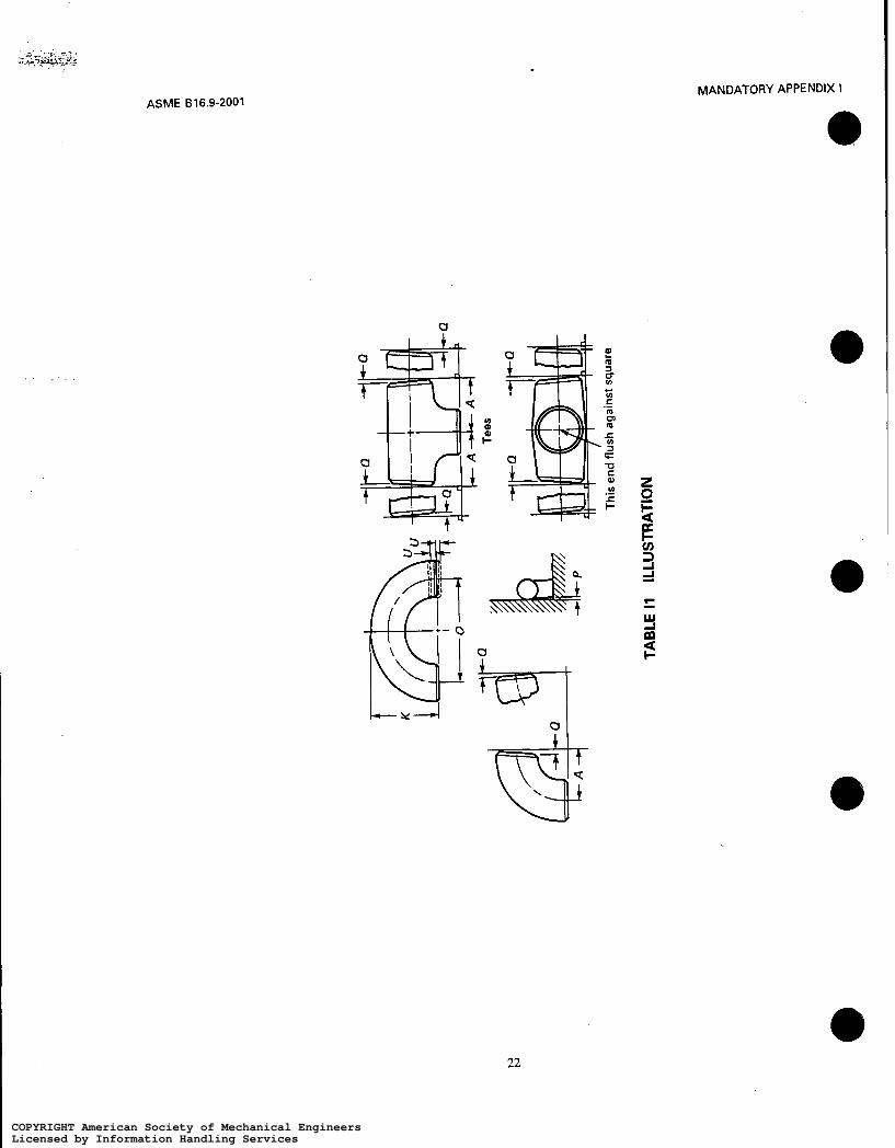
This Standard provides for a fixed position for the welding ends with reference to either the center line of the fittings or the overall dimensions. Dimensional requirements for these fittings are to be found in Tables 3 through 12 and Tables I1 through 112 of Mandatory Appendix 1.
6.2 Special Dimensions
6.2.1 Fatigue Loading. For applications where fatigue loading is a concern, required minimum dimen- sions shall be furnished by the purchaser.
6.2.2 Bore Diameter. Bore diameters, away from the ends, are not specified. If special flow path require- ments are needed, the bore dimensions shall be specified by the purchaser.
6.2.3 Stub Ends. Service conditions and joint con- o
struction often dictate stub end length requirements. Therefore, the purchaser must specify long or short pattern fitting when ordering. (See General Note (c) in Tables 10 and 19.)
ASME 816.9-2001
9 DESIGN PROOF TEST
9.1 Required Tests
Proof tests shall be made as set forth in this Standard when the manufacturer chooses proof testing to qualify the fitting design. Unless otherwise agreed upon between manufacturer and purchaser, the proof test shall be one based on the computed bursting pressure of the fitting and its connecting piping.
9.2 Test Assembly
9.2.1 Representative Components. Fittings that are representative of production and selected for test shall be identified as to material, grade, and lot, includ- ing heat treatment. They shall be inspected for dimen- sional compliance to this Standard.
9.2.2 Other Components. Straight seamless or welded pipe sections whose calculated bursting strength is at least as great as the proof test pressure as calculated in para. 9.3 shall be welded to each end of the fitting to be tested. Any internal misalignment greater than 1.5 mm (0.06 in.) shall be reduced by taper boring at a slope not over 1:3. Length of pipe sections for closures shall be as follows.
(a ) Minimum length of pipe shall be one pipe O.D. for NPS 14 (DN 350) and smaller.
(b) Minimum length of pipe shall be one-half pipe O.D. for NPS greater than 14 (DN 350).
9.3 Test Procedure
Test fluid shall be water or other liquid used for hydrostatic testing. Hydrostatic pressure shall be applied to the assembly. The test is successful if the assembly
proof test defined below,
7 SURFACE CONTOURS
planes, they shall be joined by a circular arc on the external surfaces. The arc may be terminated in tangents.
Where adjacent Openings are not in parallel withstands, without rupture, 105% of the computed e 2St p = - D
8 END PREPARATION
Unless otherwise specified, the details of the welding end preparation shall be in accordance with Table 1. Transitions from the welding bevel to outside surface of the fitting and from the root face to the inside surface of the fitting lying within the maximum envelope shown in Fig. 1 are at the manufacturer’s option except as covered in Note (5) of Fig. 1 or unless otherwise
where D = specified outside diameter of pipe P = computed minimum proof test pressure for
fitting S = actual tensile strength of the test fitting, deter-
mined on a specimen representative of the test fitting, which shall meet the tensile strength requirements of the applicable material of sec- tion 5. specifically ordered. e
3
COPYRIGHT American Society of Mechanical EngineersLicensed by Information Handling ServicesCOPYRIGHT American Society of Mechanical EngineersLicensed by Information Handling Services

ASME B16.9-2001 FACTORY-MADE WROUGHT BUTTWELDING FITTINGS
37.5 deg i2.5 deg
Note (1 1 ' 1.5 (0.06) i1 .O (0.03) (Root face)
r D
Note (1) 1 1.5 (0.06) il .O (0.03) (Root face)
1 deg
(a) Plain Bevel (b) Compound Bevel
TABLE 1 WELDING BEVELS AND ROOT FACE Nominal Wall Thickness, i End Preparation
Cut square or slightly Less than x [Note (2)l chamfer, at manufacturer's option. (Not illustrated.)
x to 22 (0.88) included Plain bevel as in sketch (a) above.
More than 22 (0.88) Compound bevel as in sketch (b) above.
GENERAL NOTES: (a) Dimensions in parentheses are in inches. (b) Other dimensions are in millimeters. NOTES: (1) See section 8 and Fig. 1 for transition contours. (2) x = 5 (0.19) for carbon steel or ferritic alloy steel and 3
(0.12) for austenitic alloy steel.
t = nominal pipe wall thickness of the pipe that fittings of the same pattern. The test of a reducing fitting qualifies reductions to smaller sizes. the fitting marking identifies
NOTE: Any dimensionally consistent system of units may be used.
9.4 Applicability of Test Results
It is not necessary to conduct an individual test of fittings with all combinations of sizes, wall thicknesses, and materiais. A successful proof test on one representa- tive fitting may represent others to the extent described in this Standard.
9.4.1 Size Range. One test fitting may be used to qualify similarly proportioned fittings with a size range from one-haif to twice that for the tested fitting. The test of a non-reducing fitting qualifies reducing
9.4.2 Thickness Range. One test fitting may used to qualify similarly proportioned fittings with ranges from one-half to three times that for the tested fitting. ..
9.4.3 Material Grades. The pressure retaining ca- pacity of a geometrically identical fitting made of various grades of steel will be directly proportional to the tensile properties of the various grades; see para 2.1. Therefore, it is necessary to test only a single material grade in a representative fitting to prove the design of the fitting.
4
COPYRIGHT American Society of Mechanical EngineersLicensed by Information Handling ServicesCOPYRIGHT American Society of Mechanical EngineersLicensed by Information Handling Services

FACTORY-MADE WROUGHT BUTWELDING FITTINGS ACME 816.9-2001
Outside I ----- /-Radius 2 0.05tmin I
Component of Fitting \ \ \ \ \ '.
I Radius 2 0.05tmin I
- . - - - - I Inside I_ itmi,, transition region -
Note (3) 1
Note (1)
NOTES: (1) The value of tmin is whichever of the following is applicable:
(a) the minimum ordered wall thickness of the pipe; (b) 0.875 times the nominal wall thickness of pipe ordered to a pipe schedule wall thickness that has an undertolerance of 12.5%.
(a) the greater of [tmin +4mm (0.16 in.)] or 1.15tmjn when ordered on a minimum wall basis; (b) the greater of [&,,in +4mm (0.16 in.)] or l.lOtnom when ordered on a nominal wall basis.
(3) Weld bevel shown is for illustration only. (4) The weld reinforcement permitted by applicable code may lie outside the maximum envelope. (5) Where transitions using maximum slope do not intersect outside surface within the
(2) The maximum thickness at the end of the component is:
transition region, as shown by phantom outline, maximum slopes shown shall be used. Alternately, radii lying within the envelope may be used.
FIG. 1 MAXIMUM ENVELOPE FOR WELDING END TRANSITIONS
10 PRODUCTION TESTS 11 TOLERANCES
Hydrostatic testing of wrought fittings is not required by this Standard. Ail fittings shall be capable of with- standing, without leakage or impairment of serviceabil- ity, a hydrostatic test pressure required by the applicable piping code for seamless pipe of material equivalent to the fitting material and of the size and wall thickness the fitting marking identifies.
Tolerances for fittings are shown in Tables 2 and I I , and apply to the nominal dimensions given in Tables 3 through 12 and Tables I2 through I1 1 . Where given in the tables, the minimum and maximum dimensions are based on these tolerances. The listings with decimals do not imply precision measurement such as use of vernier, micrometer, electronic readout equipment, etc.
5
COPYRIGHT American Society of Mechanical EngineersLicensed by Information Handling ServicesCOPYRIGHT American Society of Mechanical EngineersLicensed by Information Handling Services

, . .- ACME 816.9-2001
.
U
FACTORY-MADE WROUGHT BUTTWELDING FITTINGS
+ - o
I L Y 4
U I
U C Q In r I-
.- l-
d
6
COPYRIGHT American Society of Mechanical EngineersLicensed by Information Handling ServicesCOPYRIGHT American Society of Mechanical EngineersLicensed by Information Handling Services

FACTORY-MADE WROUGHT BUTIWELDING FIlTINGS ASME 816.9-2001
7
COPYRIGHT American Society of Mechanical EngineersLicensed by Information Handling ServicesCOPYRIGHT American Society of Mechanical EngineersLicensed by Information Handling Services

ASME B16.9-2001 FACTORY-MADE WROUGHT BUTWELDING FITTINGS
TABLE 3 DIMENSIONS OF LONG RADIUS ELBOWS
Center-to-End Nominal Pipe Outside 90Deg 45Deg Size Diameter Elbows, Elbows,
íNPSI DN at Bevel A 8
'/z "/4
1 '/4 1 '/2
21/2
3'4
1
2
3
4
5 6 8
10 12
14 16 18 20 22
24 26 28 30 32
34 36 38 40 42
44 46
15 21.3 38 16 20 [Note (111 26.7 38 19 25 33.4 38 22 32 42.2 48 25 40 48.3 57 29
50 60.3 76 35 65 73.0 95 44 80 88.9 114 51 90 101.6 133 57
1 O0 114.3 152 64
125 141.3 190 79 150 168.3 229 95 200 219.1 305 127 250 273.0 381 159 300 323.8 457 190
350 355.6 533 222 400 406.4 610 254 450 457 686 286 500 508 762 318 550 559 838 343
600 61 O 914 381 650 660 991 405 700 711 1067 438 750 762 1143 470 800 813 1219 502
850 864 1295 533 900 914 1372 565 950 965 1448 600 .,
1 O00 1016 1524 632 1050 1067 1600 660
1100 1118 1676 695 1150 1168 1753 727
48 1200 1219 1829 759
GENERAL NOTE: All dimensions are in millimeters. NOTE: (1) Äand E dimensions of 29 mm and 11 mm, respectively,
may be furnished for NPS 9 4 (DN20) atthe manufacturer's option.
8
COPYRIGHT American Society of Mechanical EngineersLicensed by Information Handling ServicesCOPYRIGHT American Society of Mechanical EngineersLicensed by Information Handling Services

FACTORY-MADE WROUGHT BUTTWELDING FITTINGS ASME 816.9-2001
TABLE 4 DIMENSIONS OF LONG RADIUS-REDUCING ELBOWS
Nominal Nominal Pipe Outside Diameter Center- Pipe Outside Diameter Center-
to-End, Size at Bevel to-End, Size at Bevel
INPS) DN Large End Small End A INPSI DN Large End Small End A
2 x 11/, 50 x 40 60.3 48.3 76 l o x 8 250 x 200 273.0 219.1 381 2 x 15% 5 0 x 32 60.3 42.2 76 1 0 x 6 250x 150 273.0 168.3 38 1 2 x 1 50 x 25 60.3 33.4 76 l o x 5 250 x 125 273.0 141.3 381
2’4 x 2 65 x 50 73.0 60.3 95 12 x 10 300 x 250 323.8 273.0 457 2l/2 x l’/z 65 x 40 73.0 48.3 95 12 x 8 300 x 200 323.8 219.1 457 2l/2 x 15% 65 x 32 73.0 42.2 95 12 x 6 300 x 150 323.8 168.3 457
3 x 2v2 80 x 65 88.9 73.0 114 14x 12 3 5 0 ~ 3 0 @ ‘ ~ 355.6 323.8 533 3 x 2 80 x 50 88.9 60.3 114 14x 10 350 x 250 355.6 273.0 533 3 x 1512 80 x 40 88.9 48.3 114 14 x 8 350 x 200 355.6 219.1 533
3‘12 X 3 90 x 80 101.6 88.9 133 1 6 x 14 400x 350 406.4 355.6 610 3‘12 X 2’/2 90 x 65 101.6 73.0 133 16 x 12 400 x 300 406.4 323.8 610 3’12 X 2 9Ox 50 101.6 60.3 133 1 6 x 10 400x 250 406.4 273.0 61 O
4 X 3’/2 100 X 90 114.3 101.6 152 18x 16 450x400 457 406.4 686 4 x 3 1OOx 80 114.3 88.9 152 1 8 x 14 450x350 457 355.6 686 4 x 2’/2 100 x 65 114.3 73.0 152 18 x 12 450 x 300 457 323.8 686 4 x 2 1OOx 50 114.3 60.3 152 1 8 x 10 450x 250 457 273.0 686
5 x 4 125 x 100 141.3 114.3 190 20 x 18 500 x 450 508 457 762 5 x 372 125x 90 141.3 101.6 190 20 x 16 500x 400 508 406.4 762 5 x 3 125x 80 141.3 88.9 190 2 0 x 14 500x 350 508 355.6 762 5 x 252 1 2 5 ~ 65 141.3 73.0 190 20 x 12 500 x 300 508 323.8 762
6 x 5 150 x 125 168.3 141.3 229 20x 10 500x 250 610 273.0 762 6 x 4 150 x 100 168.3 114.3 229 24 x 22 600 x 550 610 559 914 6 x 3’12 150 x 90 168.3 101.6 229 24x 20 600x 500 610 508 914 6 x 3 150x 80 168.3 88.9 229 2 4 x 18 600 x450 610 457 914
200 x 150 219.1 168.3 305 24 x 16 600 x 400 610 406.4 914 200 x 125 219.1 141.3 305 2 4 x 14 600x350 610 355.6 914
8 x 6 8 x 5 8 x 4 200 x 100 219.1 114.3 305 2 4 x 12 600x300 610 323.8 914
O
GENERAL NOTE: All dimensions are in millimeters.
9
COPYRIGHT American Society of Mechanical EngineersLicensed by Information Handling ServicesCOPYRIGHT American Society of Mechanical EngineersLicensed by Information Handling Services

FACTORY-MADE WROUGHT BUTTWELDING FITTINGS ASME 816.9-2001
I I 4
TABLE 5 DIMENSIONS OF LONG RADIUS RETURNS
No m i n a I Outside Center- Back-
Size at Center, Face, Pipe Diameter to- to-
íNPS) DN Bevel D K
'/2
"/4
1 '/o 1 '12
2 72
1
2
3
4
5 6 8
10 12
14 16 18 20 22 24
3 '/z
15 20 [Note (3)l 25 32 40
50 65 80 90
1 O0
125 150 200 250 300
350 400 450 500 550 600
21.3 26.7 33.4 42.2 48.3
60.3 73.0 88.9
101.6 114.3
141.3 168.3 219.1 273.0 323.8
355.6 406.4 457 508 559 610
76 76 76 95
114
152 190 229 267 305
38 1 457 61 O 762 914
1067 1219 1372 1524 1676 1829
48 51 56 70 83
106 132 159 184 210
262 313 414 518 619
711 813 914
1016 1118 1219
GENERAL NOTE: Ail dimensions are in millimeters. NOTES: (1) See Table 2 for tolerance for alignment of ends U. (2) Dimension A is equal to one-half of dimension O. (3) O and K dimentions of 57 m m and 43 mm, respectively,
may be furnished for NPS 3/4íDN 20) at the manufacturer's ODtion.
TABLE 6 DIMENSIONS OF SHORT RADIUS ELBOWS
Nominal Outside Pipe Diameter Center- Sire at to-End,
(NPS) DN Bevel A
1 25 33.4 25 1 '/4 32 42.2 32 1 '4 40 48.3 38 2 50 60.3 51 214 65 73.0 64
3
4 5 6
8 10 12 14 16
3'4 80 90
1 O0 125 150
200 250 300 350 400
88.9 101.6 114.3 141.3 168.3
219.1 273.0 323.8 355.6 406.4
76 89
102
i;* 203 254 305 356 406
18 450 457 457 20 500 508 508 22 550 559 559 24 600 610 610
GENERAL NOTE: All dimensions are in millimeters.
10
COPYRIGHT American Society of Mechanical EngineersLicensed by Information Handling ServicesCOPYRIGHT American Society of Mechanical EngineersLicensed by Information Handling Services
FACTORY-MADE WROUGHT BUTWELDING FITTINGS
\ .
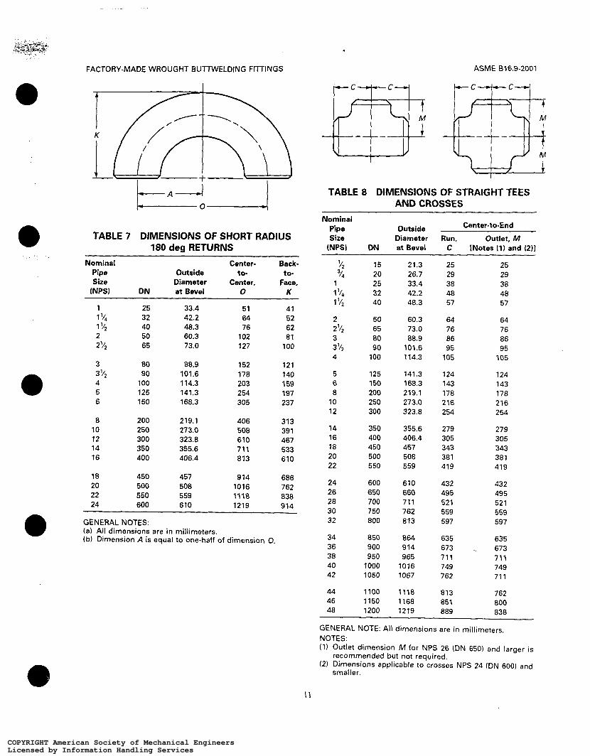
TABLE 7 DIMENSIONS OF SHORT RADIUS 180 deg RETURNS
Nominal Center- Back- Pipe Outside to- to- Size Diameter Center, Face,
íNPS) DN at Bevel O K
O
~~ ~~
1 25 33.4 51 41 1 v4 32 42.2 64 52 1 v2 40 48.3 76 62 2 50 60.3 102 81 2'/2 65 73.0 127 1 O0
3 80 88.9 152 121 3 72 90 101.6 178 140 4 1 O0 1 14.3 203 1 59 5 125 141.3 254 197 6 150 168.3 305 237
8 200 219.1 406 313 10 250 273.0 508 39 1 12 300 323.8 610 467 14 350 355.6 711 533 16 400 406.4 813 610
18 450 457 914 686 20 500 508 1016 762 22 550 559 1118 838 24 600 610 1219 91A
-
GENERAL NOTES: (a) Ali dimensions are i n millimeters. (b) Dimension A is equal to one-half of dimension O.
ASME 816.9-2001
TABLE 8 DIMENSIONS OF STRAIGHT TEES AND CROSSES
Nominal Pipe Outside Center-to-End Size Diameter Run, Outlet, M
(NPSI ON at Bevel C INotes it) and 1211
72 14
1 'I4 1 72
2'12
3 '/*
3
1
2
3
4
5 6 8 10 12
14 16 18 20 22
24 26 28 30 32
34 36 38 40 42
44 46 48
15 20 25 32 40
50 65 80 90
1 O0
125 150 200 250 300
350 400 450 500 550
600 650 700 750 800
850 900 950
1 O00 1050
1100 1150 1200
21.3 26.7 33.4 42.2 48.3
60.3 73.0 88.9 101.6 114.3
141.3 168.3 219.1 273.0 323.8
355.6 406.4 457 508 559
610 660 711 762 813
864 914 965 1016 1067
1118 1168 1219
25 29 38 48 57
64 76 86 95 105
124 143 178 216 254
279 305 343 381 419
432 495 521 559 597
635 673 711 749 762
813 851 889
25 29 38 48 57
64 76 86 95 105
124 143 178 216 254
279 305 343 381 419
432 495 521 559 597
635 673 711 749 71 1
762 800 838
GENERAL NOTE: All dimensions are in millimeters. NOTES: (1) Outlet dimension M for NPS 26 (DN 650) and larger is
(2) Dimensions applicable to crosses NPS 24 (DN 600) and recommended but not required.
smaller.
COPYRIGHT American Society of Mechanical EngineersLicensed by Information Handling ServicesCOPYRIGHT American Society of Mechanical EngineersLicensed by Information Handling Services

ASME 816.9-2001 FACTORY-MADE WROUGHT BUTWELDING FllTINGS
72 -@) k c
TABLE 9 DIMENSIONS OF REDUCING OUTLET TEES AND REDUCING OUTLET CROSSES
Center-to-End Nominal Pipe Size
Outside Diameter at Bevel Outlet, M Run,
(NPS) _ . - DN Run Outlet C
Y2 x Y2 x Y8 1 5 x 1 5 x 10 21.3 17.3 25 '12 x '12 x '14 1 5 x 1 5 x 8 21.3 13.7 25 Y4 x 74 x Y2 2 0 x 2 0 x 15 26.7 21.3 29 29 "4 x 74 x '/a 2 0 x 2 0 x 10 26.7 17.3 29 29 1 X 1 X 7 4 2 5 x 2 5 x 20 33.4 26.7 38 38 1 x 1 x '/2 25 x 25 x 15 33.4 21.3 38 38 1Y4 x I'/~ x 1 32 x 32 x 25 42.2 33.4 48 48 1 V4 x 1 V4 x Y4 32 x 3 2 x 20 42.2 26.7 48 48 I % x I Y ~ x Y ~ 3 2 x 3 2 x 15 42.2 21.3 48 48 1V2 x I ' / ~ x 1V4 40 x 4 0 x 32 48.3 42.2 57 57 l Y 2 x l'/z x 1 4 0 x 4 0 x 25 48.3 33.4 57 57 1'/2 x 1'/2 x Y4 40 x 40 x 20 48.3 26.7 57 57 11/2 x 172 x Y2 4 0 x 4 0 x 15 48.3 21.3 57 57
2 x 2 x I'/! 2 x 2 x I'/~ 2 X 2 X 1 2 X 2 X Y *
5 0 x 50 x 40 5 0 x 5 0 x 32 5 0 x 5 0 x 25 5 0 x 50 x 20
2'12 x 2'12 x 2 65 x 65 x 50 2'/2 x 2'/2 x 1'/2 65 x 65 x 40 2V2 x x 1 5% 65 x 65 x 32 272 x 2Y2 x 1 65 x 65 x 25
80 x 80 x 65 80 x 80 x 50 8Ox 8 0 x 40 80 x 80 x 32
60.3 48.3 64 60.3 42.2 64 60.3 33.4 64 60.3 26.7 64
73.0 60.3 76 73.0 48.3 76 73.0 42.2 76 73.0 33.4 76
88.9 73.0 86 88.9 60.3 86 88.9 48.3 86 88.9 42.2 86
3'/2 X 3'/2 X 3 90 x 90 x 80 101.6 88.9 95 3'/2 X 3'/2 X 2'/2 90 x 90 x 65 101.6 73.0 95 3'/2 X 3'/2 X 2 9Ox 90 x 50 101.6 60.3 95 3'12 X 352 X 1'/2 90 x 90 x 40 101.6 48.3 95
4 X 4 X 3'/2 4 X 4 X 3
4 x 4 ~ 2 4 x 4 x 2V2
4 x 4 x 1'/2
1oox 1oox 90 114.3 101.6 105 1 0 0 x 1 0 0 ~ 80 114.3 88.9 105 100 x 100 x 65 113.3 73.0 105 1 0 0 x 1 0 0 ~ 50 114.3 60.3 105 1OOx 1OOx 40 114.3 48.3 105
51 44
70 67 64 57
83 76 73 70
102 98 95 89 86
5 X 5 X 4 125x 125x 100 141.3 114.3 125 117 5 x 5 x 3v* 1 2 5 x 1 2 5 ~ 90 141.3 101.6 124 114 5 X 5 X 3 125x 125x BO 141.3 88.9 124 111 5 x 5 x 2'4 125 x 125x 65 141.3 73.0 124 108 5 x 5 ~ 2 1 2 5 x 1 2 5 ~ 50 141.3 60.3 124 105
12
COPYRIGHT American Society of Mechanical EngineersLicensed by Information Handling ServicesCOPYRIGHT American Society of Mechanical EngineersLicensed by Information Handling Services

FACTORY-MADE WROUGHT BUTTWELDING FITTINGS : .. . : -. ..
ASME 816.9-2001
TABLE 9 DIMENSIONS OF REDUCING OUTLET TEES AND REDUCING OUTLET CROSSES (CONT'D)
Nominal Pipe Size
(NPS)
Outside Diameter at Center-to-End
Run. Outlet, M Run Outlet C [Note (111
Bevel
DN __ ~
6 x 6 ~ 5 6 x 6 ~ 4
6 x 6 ~ 3 6 x 6 x 3'/2
6 x 6 x 2'/2
-~
150 x 150 x 125 150 x 150 x 100 150x 150x 90 150x 150x 80 1 5 0 x 1 5 0 ~ 65
168.3 168.3 168.3 168.3 168.3
141.3 114.3 101.6 88.9 73.0
143 143 143 143 143
137 130 127 124 121
8 x 8 ~ 6 8 x 8 ~ 5 8 x 8 ~ 4 8 x 8 x 3'/2
200 x 200 x 150 200 x 200 x 125 200 x 200 x 100 200x 200 x 90
219.1 219.1 219.1 219.1
168.3 141.3 114.3 101.6
178 178 178 178
168 162 156 152
, . 10 x 10 x 8 10 x 10 x 6 10 x 10 x 5 10 x 10 x 4
250 x 250 x 200 250 x 250 x 150 250 x 250 x 125 250 x 250 x 100
273.0 273.0 273.0 273.0
219.1 168.3 141.3 114.3
216 216 216 216
203 194 191 184
12 x 12 x 10 1 2 x 1 2 ~ 8 1 2 x 1 2 ~ 6 12 x 12 x 5
300 x 300 x 250 300 x 300 x 200 300 x 300 x 150 300 x 300 x 125
323.8 323.8 323.8 323.8
273.0 219.1 168.3 141.3
254 254 254 254
241 229 219 216
14 x 14 x 12 14 x 14 x 10 14 x 14 x 8 1 4 x 1 4 ~ 6
350 x 350 x 300 350 x 350 x 250 350 x 350 x 200 350 x 350 x 150
355.6 355.6 355.6 355.6
323.8 273.0 219.1 168.3
279 279 27 9 279
270 257 248 238
16 x 16 x 14 16 x 16 x 12 16 x 16 x 10 1 6 x 1 6 ~ 8 1 6 x 1 6 ~ 6
400 x 400 x 350 400 x 400 x 300 400 x 400 x 250 400 x 400 x 200 400 x 400 x 150
406.4 406.4 406.4 406.4 406.4
355.6 323.8 273.0 219.1 168.3
305 305 305 305 305
305 295 283 273 264
18 x 18 x 16 18 x 18 x 14 18 x 18 x 12 18 x 18 x 10 18 x 18 x 8
450 x 450 x 400 450 x 450 x 350 450 x 450 x 300 450 x 450 x 250 450 x 450 x 200
457 457 457 457 457
406.4 355.6 323.8 273.0 219.1
343 343 343 343 343
330 330 32 1 308 298
20 x 20 x 18 20 x 20 x 16 20 x 20 x 14 20X20X 12 20 x 20 x 10 20 x 20 x 8
500 x 500 x 450 500 x 500 x 400 500 x 500 x 350 500 x 500 x 300 500 x 500 x 250 500 x 500 x 200
508 508 508 508 508 508
457 406.4 355.6 323.8 273.0 219.1
38 1 381 38 1 381 38 1 381
368 356 356 346 333 324
22 x 22 x 20 22 x 22 x 18 22 x 22 x 16 22 x 22 x 14 2 2 X 2 2 X 1 2 22 x 22 x 10
550 x 550 x 500 550 x 550 x 450 550 x 550 x 400 550 x 550 x 350 550 x 550 x 300 550 x 550 x 250
559 559 559 559 559 559
508 457 406.4 355.6 323.8 273.0
419 419 419 419 419 419
406 394 38 1 381 37 1 359
(continued)
13
COPYRIGHT American Society of Mechanical EngineersLicensed by Information Handling ServicesCOPYRIGHT American Society of Mechanical EngineersLicensed by Information Handling Services

ASME 816.9-2001 FACTORY-MADE WROUGHT BUTTWELDING FITTINGS
TABLE 9 DIMENSIONS OF REDUCING OUTLET TEES AND REDUCING OUTLET CROSSES (CONT'D)
Outside Diameter at Center-to-End Nominal
Bevel Run, Outlet, M Pipe Size
W S ) DN Run Outlet C [Note Ilil
24 x 24 x 22 24 x 24 x 20 24 x 24 x 18 2 4 x 2 4 ~ 16 24 x 24 x 14 24 x 24 x 12 24 x 24 x 10
26 x 26 x 24 26 x 26 x 22 26 x 26 x 20 26 x 26 x 18 26 x 26 x 16 26 x 26 x 14 26 x 26 x 12
28 x 28 x 26 28 x 28 x 24 28 x 28 x 22 28 x 28 x 20 28 x 28 x 18 28 x 28 x 16 28 x 28 x 14 28 x 28 x 12
30 x 30 x 28 30 x 30 x 26 30 x 30 x 24 30 x 30 x 22 30 x 30 x 20 30 x 30 x 18 30 x 30 x 16 30 x 30 x 14 30 x 30 x 12 30 x 30 x 10
32 x 32 x 30 32 x 32 x 28 32 x 32 x 26 32 x 32 x 24 32 x 32 x 22 32 x 32 x 20 32 x 32 x 18 32 x 32 x 16 32 x 32 x 14
34 x 34 x 32 34 x 34 x 30 34 x 34 x 28 34 x 34 x 26 34 x 34 x 24 34 x 34 x 22 34 x 34 x 20
600 x 600 x 550 600 x 600 x 500 600 x 600 x 450 600 x 600 x 400 600 x 600 x 350 600 x 600 x 300 600 x 600 x 250
650 x 650 x 600 650 x 650 x 550 650 x 650 x 550 650 x 650 x 450 650 x 650 x 400 650 x 650 x 350 650 x 650 x 300
700 x 700 x 650 700 x 700 x 600 700 x 700 x 550 700 x 700 x 500 700 x 700 x 450 700 x 700 x 400 700 x 700 x 350 700x 700 x 300
750 x 750 x 700 750 x 750 x 650 750 x 750 x 600 750 x 750 x 550 750 x 750 x 500 750 x 750 x 450 750 x 750 x 400 750 x 750 x 350 750 x 750 x 300 750 x 750 x 250
800 x 800 x 750 800 x 800 x 700 800 x 800 x 650 800 x 800 x 600 800 x 800 x 550 800 x 800 x 500 800 x 800 x 450 800 x 800 x 400 800 x 800 x 350
850 x 850 x 800 850 x 850 x 750 850 x 850 x 700 850 x 850 x 650 850 x 850 x 600 850 x 850 x 550 850 x 850 x 500
61 O 610 610 610 610 610 61 O
660 660 660 660 660 660 660
711 71 1 71 1 711 71 1 71 1 71 1 711
762 762 762 762 762 762 762 762 762 762
813 813 813 813 813 81 3 813 813 813
864 864 864 864 864 864 864
559 508 457 406.4 355.6 323.8 273.0
610 559 508 457 406.4 355.6 323.8
660 61 O 559 508 457 406.4 355.6 323.8
71 1 660 610 559 508 457 406.4 355.6 323.8 273.0
762 711 660 610 559 508 457 406.4 355.6
813 762 711 600 610 559 508
432 432 432 432 432 432 432
495 495 495 495 495 495 495
521 521 52 1 521 521 521 521 521
559 559 559 559 559 559 559 559 559 559
597 597 597 597 597 597
597 597
635 635 635 635 635 635 635
597
432 432 419 406 406 397 384
470 483 .i 457 444 432 432 422
521 508 495 483 470 457 457
-0 546 546 533 52 1 508 495 483 483 473 460
584 572
::s. 546
533 521 508 508
622 610 597 597 584 572 559
14
COPYRIGHT American Society of Mechanical EngineersLicensed by Information Handling ServicesCOPYRIGHT American Society of Mechanical EngineersLicensed by Information Handling Services

ASME 616.9-2001 FACTORY-MADE WROUGHT BUTTWELDING FITTINGS
TABLE 9 DIMENSIONS OF REDUCING OUTLET TEES AND REDUCING OUTLET CROSSES W " D )
Nominal Pipe Size
(NPS) ON
Outside Diameter at Center-to-End
Outlet, M Run Outtat C INote 11ì1
Run, Bevel
34 x 34 x 18 34 x 34 x 16
36 x 36 x 34 36 x 36 x 32 36 x 36 x 30 36 x 36 x 28 36 x 36 x 26 36 x 36 x 24 36 x 36 x 22 36 x 36 x 20 36 x 36 x 18 36 x 36 x 16
38 x 38 x 36 38 x 38 x 34 38 x 38 x 32 38 x 38 x 30 38 x 38 x 28 38 x 38 x 26 38 x 38 x 24 38 x 38 x 22 38 x 38 x 20 38 x 38 x 18
40 x 40 x 38 40 x 40 x 36 40 x 40 x 34 40 x 40 x 32 40 x 40 x 30 40 x 40 x 28 40 x 40 x 26 40 x 40 x 24 40 x 40 x 22 40 x 40 x 20 4 0 x 4 0 ~ 18
42 x 42 x 40 42 x 42 x 38 42 x 42 x 36 42 x 42 x 34 42 x 42 x 32 42 x 42 x 30 42 x 42 x 28 42 x 42 x 26 42 x 42 x 24 42 x 42 x 22 42 x 42 x 20 42 x 42 x 18 42 x 42 x 16
4 4 x 4 4 ~ 4 2 4 4 x 4 4 ~ 4 0
850 x 850 x 450 850 x 850 x 400
9OOx 900 x850 9oox 900 x 800 9OOx 900 x 750 9OOx 900 x 700 9OOx 900 x 650 900x 900 x 600 9OOx 900 x 550 9OOx 900 x 500 9OOx 900 x 450 9OOx 900 x 400
950 x 950 x 900 950 x 950 x 850 950 x 950 x 800 950 x 950 x 750 950 x 950 x 700 950 x 950 x 650 950 x 950 x 600 950 x 950 x 550 950 x 950 x 500 950 x 950 x 450
1000 x 1000 x 950 1000 x 1000 x 900 1000 x 1000 x 850 1000 x 1000 x 800 1000 x 1000 x 750 1000 x 1000 x 700 1000 x 1000 x 650 1000 x 1000 x 600 1000 x 1000 x 550 1000 x 1000 x 500 1000 x 1000 x 450
1050 x 1050 x 1000 1050 x 1050 x 950 1050 x 1050 x 900 1050 x 1050 x 850 1050 x 1050 x 800 1050 x 1050 x 750 1050 x 1050 x 700 1050 x 1050 x 650 1050 x 1050 x 600 1050 x 1050 x 550 1050 x 1050 x 500 1050 x 1050 x 450 1050 x 1050 x 400
1100 x 1100 x 1050 1100 x 1100 x 1000
864 864
914 914 914 914 914 97 4 914 914 914 914
965 965 965 965 965 965 965 965 965 965
1016 1016 1016 1016 1016 1016 1016 1016 1016 1016 1016
1067 1067 1067 1067 1067 1067 1067 1067 1067 1067 1067 1067 1067
1118 1118
457 406.4
864 813 762 71 1 660 610 559 508 457 406.4
914 864 813 762 71 1 660 61 O 559 508 457
965 914 864 813 762 71 1 560 610 559 508 457
1016 968 914 864 813 762 71 1 660 610 559 508 457 406.4
1067 1016
635 635
67 3 673 673 673 673 673 673 673 673 673
71 1 71 1 71 1 711 71 1 711 71 1 71 1 711 711
749 749 7 49 7 49 749 749 749 749 749 7 49 749
762 762 762 762 762 762 762 762 762 7 62 762 762 762
813 813
546 533
660 648 635 622 622 610 597 584 57 2 559
71 1 698 686 61 3 648 648 635 622 610 597
749 737 724 71 1 69 8 673 673 660 648 635 622
711 71 1 71 1 71 1 711 711 698 698 660 660 660 648 635
762 7 49
~ _ _ _ (continued)
15
COPYRIGHT American Society of Mechanical EngineersLicensed by Information Handling ServicesCOPYRIGHT American Society of Mechanical EngineersLicensed by Information Handling Services

ASME 816.9-2001 FACTORY-MADE WROUGHT BUTTWELDING FITTINGS
. . . .
TABLE 9 DIMENSIONS OF REDUCING OUTLET TEES AND REDUCING OUTLET CROSSES ICONT'D)
Nominal Outside Diameter at Center-to-End
Bevel Run, Outlet, M Pipe Size
íNPS) DN Run Outlet C [Note ilII
4 4 x 4 4 ~ 3 8 1100 x 1100 x 950 1118 965 813 737 4 4 x 4 4 ~ 3 6 1100 x 1100 x 900 1118 914 813 724 4 4 X 4 4 X 3 4 1100 x 1100 x 850 1118 864 813 724 4 4 x 4 4 ~ 3 2 1100 x 1100 x 800 1118 813 813 711 4 4 x 4 4 ~ 3 0 1100 x 1100 x 750 1118 762 813 711 4 4 x 4 4 ~ 2 8 1100 x 1100 x 700 1118 711 813 698 4 4 x 4 4 ~ 2 6 1100 x 1100 x 650 1118 660 813 698 4 4 ~ 4 4 x 2 4 1100 x 1100 x 600 1118 610 813 4 4 X 4 4 X 2 2 1100 x 1100 x 550 1118 559 813 4 4 X 4 4 X 2 0 1100 x 1100 x 500 1118 508 813 686
46 x 46 x 44 46 x 46 x 42 46 x 46 x 40 46 x 46 x 38 46 x 46 x 36 46 x 46 x 34 46 x 46 x 32 46 x 46 x 30 46 x 46 x 28 46 x 46 x 26 46 x 46 x 24 46 x 46 x 22
1150 x 1150 x 1100 1150 x 1150 x 1050 1150 x 1150 x 1000 1150 x 1150 x 950 1150 x 1150 x 900 1150x 1150x850 1150 x 1150 x 800 1150 x 1150 x 750 1150 x 1150 x700 1150x 1150x650 1150 x 1150 x 600 1150 x 1150 x 550
1168 1168 1168 1168 1168 1168 1168 1168 1168 1168 1168 1168
1118 1067 1016 965 914 864
762 711 660 610 559
a i3
851 851 851 85 1 851 85 1 851 851 851 851 85 1 851
800 787 775 762 762 749 749 737 737 7 37 724 724
48 x 48 x 46 1200 x 1200 x 1150 1219 1168 889 48 x 48 x 44 1200 x 1200 x 1100 1219 1118 889 48 x 48 x 42 1200 x 1200 x 1050 1219 1067 889 48 x 48 x 40 1200 x 1200 x 1 O00 1219 1016 889 48 x 48 x 38 1200 x 1200 x 950 1219 965 889 48 x 48 x 36 1200 x 1200 x 900 1219 914 889 48 x 48 x 34 1200 x 1200 x 850 ,1219 864 889 48 x 48 x 32 1200 x 1200 x 800 1219 813 889 48 x 48 x 30 1200 x 1200 x 750 1219 . 762 889 48 x 48 x 28 1200 x 1200 x 700 1219 71 1 889 48 x 48 x 26 1200 x 1200 x 650 1219 660 889 48 x 48 x 24 1200 x 1200 x 600 1219 610 889 48 x 48 x 22 1200 x 1200 x 550 1219 559 889
GENERAL NOTE: All dimensions are in millimeters. NOTE: (1) Outlet dimension M for run sizes NPS 14 IDN 350) and larger is recommended but not required.
813 813 813 7 87 787 787 762 762 762 7 37 737
16
COPYRIGHT American Society of Mechanical EngineersLicensed by Information Handling ServicesCOPYRIGHT American Society of Mechanical EngineersLicensed by Information Handling Services

FACTORY-MADE WROUGHT BUTTWELDING FITTINGS ASME 816.9-2001
Note square corner
Note (1)
Enlarged Section of Lap
L F - I
TABLE 10 DIMENSIONS OF LAP JOINT STUB ENDS
Nominal Long Pattern Short Pattern Radius of Diameter Pipe
of Lap, G Size (NPS) DN Max. Min. [Notes (3), (411 [Notes 13). (4)1 [Note 1511 [Note (611
Outside Diameter of Barrel Length, F Length, F Fillet, R
_c .? - '
'12 15 22.8 20.5 76 "4 20 28.1 25.9 76
1 25 35.0 32.6 102 1 Y4 32 43.6 41.4 102 1 5; 40 49.9 47.5 102
2 50 62.4 59.5 152 2 Y2 65 75.3 72.2 152 3 80 91.3 88.1 152 3'12 90 104.0 100.8 152 4 1 O0 116.7 113.5 152
5 125 144.3 140.5 203 6 150 171.3 167.5 203 8 200 222.1 218.3 203
10 250 277.2 272.3 254 12 300 328.0 323.1 254
14 350 359.9 354.8 305 16 400 411.0 405.6 305 18 450 462 456 305 20 500 514 507 305
51 51 51 51 51
64 64 64 76 76
76 89
102 127 152
152 152 152 152
3 35 3 43 3 51 5 64 6 73
8 92 8 106
10 127 10 140 11 157
11 185 13 218 13 270 13 324 13 38 1
13 413 13 47 O 13 533 13 584
22 550 565 558 305 152 13 64 1 24 600 616 609 305 152 13 692
GENERAL NOTES: (a) All dimensions are in millimeters, (b) See Table 2 for tolerances. (c) Service conditions and joint construction often dictate stub end length requirements. Therefore, the purchaser must specify
NOTES: (1) Gasket face finish shall be in accordance with ASME 816.5 for raised face flanges. (2) The lap thickness Tshall not be less than nominal pipe wall thickness. See Table 2 for maximum tolerance. (3) When short pattern stub ends are used with larger flanges in Classes 300 and 600, (PN50 & PN110) and with most sizes in
Classes 900 (PN150) and higher, and when long pattern stub ends are used with larger flanges in Classes 1500 and 2500, (PN260 AND PN420) it may be necessary to increase the length of the stub ends in order to avoid covering the weld with the flange. Such increases in length shall be a matter of agreement between the manufacturer and purchaser.
(4) When special facings such as tongue and groove, male and female, etc., are employed, additional lap thickness must be provided and such additional thickness shall be in addition to (not included in) the basic length F.
(5) These dimensions conform to the radius established for lap joint flanges in ASME 816.5. Pipe Flanges and Flanged Fittings. (6) This dimension conforms to standard machined facings shown in ASME B16.5. The back face of the lap shall be machined
to conform to the surface on which it seats. Where ring joint facings are to be applied, use dimension Kas given in ASME 616.5.
long or short pattern fitting when ordering.
17
COPYRIGHT American Society of Mechanical EngineersLicensed by Information Handling ServicesCOPYRIGHT American Society of Mechanical EngineersLicensed by Information Handling Services

...... -. . . . . ' .
ASME 816.9-2001 FACTORY-MADE WROUGHT BUTTWELDING FITTINGS
TABLE 11 DIMENSIONS OF CAPS Nominal Outside Limiting Wall Pipe Site Diameter Length, E Thickness for Length, E
INPSI DN at Bevel [Note (111 Length, E [Note (211
'/2 "4
1 '/4 1 '/z
21/2
1
2
3
4
5 6 8
10 12
14 16 18 20 22
24 26 28 30 32
34 36 38 40 42
44 46 48
3'/2
15 21.3 25 4.57 25 20 26.7 25 3.81 25 25 32 40
50 65 80 90
1 O0
125 150 200 250 300
350 400 450 500 550
600 650 700 750 800
850 900 950
1 O00 1050
1100 1150 1200
33.4 42.2 48.3
60.3 73.0 88.9
101.6 114.3
141.3 168.3 219.1 273.0 323.8
355.6 406.4 457 508 559
610 660 71 1 762 813
864 914 965
1016 1067
1118 1168 1219
38 38 38
38 38 51 64 64
76 89
102 127 152
165 178 203 229 254
267 267 267 267 267
267 267 305 305 305
343 343 343
4.57 4.83 5.08
5.59 7.1 1 7.62 8.13 8.64
9.65 10.92 12.70 12.70 12.70
12.70 12.70 12.70 12.70 12.70
12.70 ... ... ... ... . . . . . . . . I
...
. . .
...
. . .
...
38 38 38
44 51 64 76 76
89 102 127 152 178
191 203 229 254 254
305 ... ... ... ... ... . . . ... . . . ... ' ...
...
... GENERAL NOTES: (a) All dimensions are in millimeters. (b) The shape of these caps shall be elipsoidal and shall conform to the shape requirements
as given in the ASME Boiler and Pressure Vessel Code. NOTES: (1) Length E applies for thickness not exceeding that given in column "Limiting Wall Thickness
for Length E." (2) Length El applies for thickness greater than that given in column "Limiting Wall Thickness"
for NPS 24 (DN 600) and smaller. For NPS 26 (DN 65) and larger, length El shall be by agreement between manufacturer and purchaser.
18
COPYRIGHT American Society of Mechanical EngineersLicensed by Information Handling ServicesCOPYRIGHT American Society of Mechanical EngineersLicensed by Information Handling Services

FACTORY-MADE WROUGHT BUllWELDING FIlTINGS ASME 816.9-2001
Note (1)
TABLE 12 DIMENSIONS Outside
Diameter at Bevel
Nominal Pipe Large Small End-to-End, Size (NPSi DN End End H
20 X 15 20 x 10 25 X 20 25 X 15
32 X 25 32 x 20 32 X 15
40 X 32 40 X 25 40 x 20 40 X 15
50 x 40 50 x 32
50 x 20
65 x 50 65 x 40 65 x 32 65 x 25
80 x 65 80 x 50 80 X 40 80 x 32
90 x 80 90 x 65 90 x 50 90 x 40 90 x 32
100 x 90 100 x 80 100 x 65 100 x 50 100 x 40
50 X 25
26.7 26.7 33.4 33.4
42.2 42.2 42.2
48.3 48.3 48.3 48.3
60.3 60.3 60.3 60.3
73.0 73.0 73.0 73.0
88.9 88.9 88.9 88.9
101.6 101.6 101.6 101.6 101.6
114.3 114.3 114.3 114.3 114.3
21.3 17.3 26.7 21.3
33.4 26.7 21.3
42.2 33.4 26.7 21.3
48.3 42.2 33.4 26.7
60.3 48.3 42.2 33.4
73.0 60.3 48.3 42.2
88.9 73.0 60.3 48.3 42.2
101.6 88.9 73.0 60.3 48.3
38 38 51 51
51 51 51
64 64 64 64
76 76 76 76
89 89 89 89
89 89 89 89
102 102 102 102 102
102 102 102 102 102
OF REDUCERS Outside
Diameter at Bevel
Nominal Pipe Large Small End-to-End, Sire iNPS) DN End End H
5 x 4
5 x 3
5 x 2
6 x 5 6 x 4 6 X 3‘/2 6 x 3 6 X 2‘/2
5 X 3’/2
5 x 2’4
8 x 6 8 x 5 8 x 4 8 X 3’/2
10 x 8 10 X 6 10 x 5 10 x 4
12 x 10 12 X 8 12 x 6 12 x 5
14X 12 14 X 10 14 X 8 14 x 6
16 X 14 16 x 12 16 X 10 16 x 8
18 X 16 18 X 14 18 x 12 18 x 10
125 X 100 125 x 90 125 X 80 125 X 65 125 x 50
150 x 125 150 X 100 150 x 90 150 x 80 150 x 65
200 X 150 200 x 125 200 x 100 200 x 90
250 X 200 250 x 150 250 X 125 250 X 100
300 X 250 300 x 200 300 X 150 300 X 125
350 x 300 350 x 250 350 X 200 350 x 150
400 X 350 400 X 300 400 X 250 400 X 200
450 X 400 450 X 350 450 X 300 450 X 250
141.3 141.3 141.3 141.3 141.3
168.3 168.3 168.3 168.3 168.3
219.1 219.1 219.1 219.1
273.0 273.0 273.0 273.0
323.8 323.8 323.8 323.8
355.6 355.6 355.6 355.6
406.4 406.4 406.4 406.4
457 457 457 457
114.3 101.6 88.9 73.0 60.3
141.3 114.3 101.6 88.9 73.0
168.3 141.3 114.3 101.6
219.1 168.3 141.3 114.3
273.0 219.1 168.3 141.3
323.8 273.0 219.1 168.3
355.6 323.8 273.0 219.1
406.4 355.6 323.8 273.0
127 127 127 127 127
140 140 140 140 140
152 152 152 152
178 178 178 178
203 203 203 203
330 330 330 330
356 356 356 356
381 38 1 381 38 1
(continued)
19
COPYRIGHT American Society of Mechanical EngineersLicensed by Information Handling ServicesCOPYRIGHT American Society of Mechanical EngineersLicensed by Information Handling Services

ASME 816.9-2001
Outside ~~ ~
Outside Diameter at
Bevel
Nominal Pipe Large Small End-to-End, Size (NPS) DN End End 'H
20 X 18 20 X 16 20 X 14 20 x 12
22 x 20 22 X 18 22 X 16 22 X 14
24 X 22 24 X 20 24 X 18 24 X 16
- ..- .
26 X 24 26 X 22 26 X 20 26 X 18
28 X 26 28 X 24 28 x 22 28 x 20
30 X 28 30 X 26 30 X 24 30 x 22
32 X 30 32 X 28 32 X 26 32 x 24
34 x 32 34 X 30 34 X 28 34 X 26
FACTORY-MADE WROUGHT BUTTWELDING FITTINGS
500 x 450 508 500 x 400 508 500 x 350 508 500 X 300 508
550 x 500 559 550 x 450 559 550 x 400 559 550 x 350 559
600 X 550 610 600 x 500 610 600 X 450 610 600 X 400 610
650 X 600 660 650 x 550 660 650 x 500 660 650 x 450 660
700 X 650 711 700 X 600 711 700 X 550 711 700 x 500 711
750 X 700 762 750 X 650 762 750 X 600 762 750 X 550 762
ao0 x 750 813 800 X 700 813 800 X 650 813 800 X 600 813
850 X 800 864 850 X 750 864 850 X 700 864 850 X 650 864
457 406.4 355.6 323.8
508 457 406.4 355.4
559 508 457 406.4
61 O 559 508 457
660 61 O 508 457
71 1 660 610 508
762 71 1 660 610
813 762 660 61 O
508
508 508
508 508
508
508
508
508 508 508 508
610 61 O 610 610
610 610 610 610
610 610 610 610
610 610 610 610
610 610 610 610
Diameter at Bevel
Large Small End-to-End, Nominal Pipe Size INPSI DN End End H
36 X 34 36 x 32 36 X 30 36 X 28 36 X 26
38 x 36 38 X 34 38 x 32 38 x 30 38 X 28 38 x 26
40 X 38 40 x 36 40 X 34 40 x 32 40 x 30
42 X 40 42 x 38 42 x 36 42 X 34 42 X 32 42 X 30
44 X 42 44 x 40 44 x 38 44 x 36
46 X 44 46 x 42 46 X 40 46 x 38
48 x 46 48 X 44 48 X 42 48 X 40
900 x 850 914 900 x 800 914 900 x 750 914 900 X 700 914 900 X 650 914
950 X 900 965 950 x 850 965 950 X 800 965 950 x 750 965 950 X 700 965 950 X 650 965
1000 X 950 1016 1000 X 900 1016 1000 X 850 1016 1000 X 800 1016 1000 X 750 1016
1050 X 1000 1067 1050 X 950 1067 1050 x 900 1067 1050 X 850 1067 1050 X 800 1067 1050 x 750 1067
1100 X 1050 1118 1100 X 1000 1118 1100 X 950 1118 1100 x 900 1118
1150 X 1100 1168 1150 x 1050 1168 1150 X 1000 1168 1150 x 950 1168
1200 X 1150 1219 1200 X 1100 1219 1200 X 1050 1219 1200 X 1000 1219
864 813 762 660 610
914 864 813 762 711 660
965 914 864 813 762
1016 965 914 864 813 762
1067 1016 965 914
1118 1067 1016 965
1168 1118 1067 1016
610 610 610 610 610
610
::o0 61 O 610 610
610 610 610 610 610
610 610 610 610
E 610 610 610 610
71 1 711 711 711
711 711 71 1
, 71 1 ~~
GENERAL NOTE: All dimensions are in millimeters. NOTE: (1) While the figure illustrates a "bell shaped" reducer, the use of conical reducer is not prohibited.
20
COPYRIGHT American Society of Mechanical EngineersLicensed by Information Handling ServicesCOPYRIGHT American Society of Mechanical EngineersLicensed by Information Handling Services

ASME 816.9-2001
MANDATORY APPENDIX I INCH TABLES
This Appendix provides tables of the standard inch dimensions for fittings.
21
COPYRIGHT American Society of Mechanical EngineersLicensed by Information Handling ServicesCOPYRIGHT American Society of Mechanical EngineersLicensed by Information Handling Services
ASME 816.9-2001
@ e - o
\ I
U m
MANDATORY APPENDIX I
ä pc
22
COPYRIGHT American Society of Mechanical EngineersLicensed by Information Handling ServicesCOPYRIGHT American Society of Mechanical EngineersLicensed by Information Handling Services

MANDATORY APPENDIX I ASME 616.9-2001
a, v) Co 7 N O O
a, ffl
O
z 2 8 o
2 c N w O c O c O
e z o o
9
W U
al U VI .- cn O z 2
F - m o o
G m c O -
N N m
2 o
O
O
W
+ o
W W
O 9 0 2 + o + o 4 0
i: n a 3
E w
ci .- O
-J
o -I
n
m + o o 9 o 9 W o 9 W o 9 W
+ o + o + o W '
o 9 : + o
m + o o 9
m m W o 9 o 9 o 9 + o + o + o
W ' o 9 : + o
W
O 9 m m W
O O O 9 9 9
(0
O 9
v) c 5 a o>
w o K
P z U K w O
I- 8 Eo
In
2 In In In N 2 2 O
In
O N
o W O - In
O N In In Co
N N O O 2
m c! O VI
m * a al U
al c 0:
hl In In N N o O O
- Ln cn N O z
W
O 9 W W a,
9 8 8 O
ffl O F O o
W W m
O O O 9 9 9
m
O o o 2
W W
O O o 9 0 2 F F
o o
W In In W m O W z y 2 F o 9 8 + o + o + o + o
U N O m c O * O O W r4 N
23
COPYRIGHT American Society of Mechanical EngineersLicensed by Information Handling ServicesCOPYRIGHT American Society of Mechanical EngineersLicensed by Information Handling Services

,. , . , I , .i-.
. _. .r . , r ... .. .&.. :..c..,..-
Center-to-End Nominal . -.. Pipe Outside 90 Deg 45 Deg
Sire Diameter Elbows, Elbows, (NPS) at Bevel A B
. . . 1. .
y... .. , - y:., .... -::.,>.. -.
0.84 1.50 0.62 , , . . j . 3/4 [Note il)] 1 .O5 1.50 0.75
1 1.32 1.50 0.88 1 '/d 1.66 1.88 1 .o0
'4 . . . ,. .
ASME 816.9-2001
Center-to-End Nominal Pipe Outside 90 Deg Size Diameter Elbows,
INPSI at Bevel A
16 16.00 24.00 10.00 18 18.00 27.00 11.25 20 20.00 30.00 12.50 22 22.00 33.00 13.50
MANDATORY APPENDIX I
1.90 2.25 1.12 2.38 3.00 1.38 2.88 3.75 1.75 3.50 4.50 2.00
24 24.00 36.00 15.00 26 26.00 39.00 16.00 28 28.00 42.00 17.25. 30 30.00 45.00 18.50
1 '/2
2 ?; 2
3
352 4 5 6
8 10 12 14
4.00 4.50 5.56 6.62
8.62 10.75 12.75 14.00
5.25 6.00 7.50 9.00
12.00 15.00 18.00 21.00
2.25 2.50 3.12 3.75
5.00 6.25 7.50 8.75
32 32.00 48.00 19.75 34 34.00 51.00 21.00 36 36.00 54.00 38 38.00 57.00
40 40.00 60.00 24.88- 42 42.00 63.00 26.00 44 44.00 66.00 27.38 46 46.00 69.00 28.62 48 48.00 72.00 29.88
GENERAL NOTE: All dimensions are in inches. NOTE: (1) A and 8 dimensions of 1.12 in. and 0.44 in., respectively, may be furnished for NPS 3/4 at the manufacturer's option.
24
COPYRIGHT American Society of Mechanical EngineersLicensed by Information Handling ServicesCOPYRIGHT American Society of Mechanical EngineersLicensed by Information Handling Services

MANDATORY APPENDIX I ASME 616.9-2001
TABKE 13 DIMENSIONS OF LONG RADIUS REDUCING ELBOWS
Nominal Pipe Sire
INPS) O 2 x 1 ’/2 2 x l’i 2 x 1
4 x 3
4 x 2 4 x 2’/2
5 x 4
5 x 3 5 X 3’/2
5 x 2‘12
6 x 5 6 x 4
8 x 5 8 x 4
Outside Diameter at Bevel
Large End Small End
Center- to-
End, A
2.38 2.38 2.38
2.88 2.88 2.88
3.50 3.50 3.50
4.00 4.00 4.00
4.50 4.50 4.50 4.50
5.56 5.56 5.56 5.56
6.62 6.62 6.62 6.62
8.62 8.62 8.62
1.90 1.66 1.32
2.38 1.90 1.66
2.88 2.38 1.90
3.50 2.88 2.38
4.00 3.50 2.88 2.38
4.50 4.00 3.50 2.88
5.56 4.50 4.00 3.50
6.62 5.56 4.50
3.00 3.00 3.00
3.75 3.75 3.75
4.50 4.50 4.50
5.25 5.25 5.25
6.00 6.00 6.00 6.00
7.50 7.50 7.50 7.50
9.00 9.00 9.00 9.00
12.00 12.90 12.00
Nominal Center- Outside Diameter
at Bevel to-
End, Pipe Size
íNPS1 Large End Small End A
10 x 8 10 x 6 10 x 5
12 x 10 12 x 8 12 x 6
14 X 12 14 x 10 14 X 8
16 X 14 16 x 12 16 X 19
18 x 16 18 X 14 18 x 12 18 X 10
20 x 18 20 X 16 20 X 14 20 x 12
20 x 10 24 X 22 24 x 20 24 X 18
24 X 16 24 x 14 24 X 12
10.75 10.75 10.75
12.75 12.75 12.75
14.00 14.00 14.00
16.00 16.00 16.00
18.00 18.00 18.00 18.00
20.00 20.00 20.00 20.00
20.00 24.00 24.00 24.00
24.00 24.00 24.00
8.62 6.62 5.56
10.75 8.62 6.62
12.75 10.75 8.62
14.00 12.75 10.75
16.00 14.00 12.75 10.75
18.00 16.00 14.00 12.75
10.75 22.00 20.00 18.00
16.00 14.00 12.75
15.00 15.00 15.00
18.00 18.00 18.00
21.00 21.00 21.00
24.00 24.00 24.00
27.00 27.00 27.00 27.00
30.00 30.00 30.00 30.00
30.00 36.00 36.00 36.00
36.00 36.00 36.00
GENERAL NOTE: All dimensions are in inches.
25
COPYRIGHT American Society of Mechanical EngineersLicensed by Information Handling ServicesCOPYRIGHT American Society of Mechanical EngineersLicensed by Information Handling Services

<-
c . . 1 i
_,__ -:*.:*> , _ . _ ,.... -. .. . . . . , . .. . , . . . . ~ ..A.'.
ASME 816.9-2001
U [Note
MANDATORY APPENDIX I
TABLE 14 DIMENSIONS OF LONG RADIUS RETURNS
Nominal Pipe Outside Center- Back- Size Diameter to-Center, to-Face,
(NPS) at Bevel O K
TABLE 15 DIMENSIONS OF SHORT RADIUS ELBOWS
Outside Nominal
Pipe Sire
Diameter at
Bevel
to- End,
A ~~ ~ ~~
'12 0.84 3.00 1 .88
1 1.32 3.00 2.19 1 '14 1.66 3.75 2.75 1 '12 1.90 4.50 3.25
[Note (311 1.05 3.00 2.00
5 6 8 10 12
2.38 6.00 4.19 2.88 7.50 5.19 3.50 9.00 6.25 4.00 10.50 7.25 4.50 12.00 8.25
5.56 15.00 10.3 1 6.62 18.00 12.31 8.62 24.00 16.31 10.75 30.00 20.38 12.75 36.00 24.38
14 14.00 42.00 28.00 16 16.00 48.00 32.00 18 18.00 54.00 36.00 20 20.00 60.00 40.00 22 22.00 66.00 44.00 24 24.00 72.00 48.00
GENERAL NOTE: All dimensions are in inches. NOTES: (1) See Table Il for tolerance for alignment of ends, U. (2) Dimension A is equal to one-half of dimension O. (3) Oand Kdimensions of 2.25 in. and 1.69 in. respectively,
may be furnished for NPS 3/4 atthe manufacturer's option.
1 1% 1 '12
2'12 -2
1.32 1.66 1.90 2.38 2.88
1.00 1.25 1.50 2.00 2.50
3
4 5 6
3 '12
8 10 12 14 16
18 20 22 24
3.50 4.00 4.50 5.56 6.62
8.62 10.75 12.75 14.00 16.00
18.00 20.00 22.00 24.00
3.00 3.40 4.00
10.00 12.00 14.00 16.00
18.00 20.00 22.00 24.00
GENERAL NOTE: All dimensions are in inches.
26
COPYRIGHT American Society of Mechanical EngineersLicensed by Information Handling ServicesCOPYRIGHT American Society of Mechanical EngineersLicensed by Information Handling Services

MANDATORY APPENDIX I ASME 816.9-2001
TABLE 16 DIMENSIONS OF SHORT RADIUS O 180 deg RETURNS - e -
Outside Nominal Diameter Center- Back-
Pipe at to-Center, to-Face, Size Bevel o K
1 1.32 2.00 1.62 1 Y4 1.66 2.50 2.06
2 2.38 4.00 3.19 1 1.90 3.00 2.44
2'/2 2.88 5.00 3.94
3 3.50 6.00 4.75
5 5.56 10.00 7.75
3'/* 4.00 7.00 5.50 4 4.50 8.00 6.25
6 6.62 12.00 9.31
8 8.62 16.00 12.31 10 10.75 20.00 15.38 12 12.75 24.00 18.38
16 16.00 32.00 24.00 14 14.00 28.00 21.00
18 18.00 36.00 27.00 20 20.00 40.00 30.00 22 22.00 44.00 33.00 24 24.00 48.00 36.00
GENERAL NOTES: (a) All dimensions are in inches. íb) Dimension A is equal to one-half of dimension O.
TABLE 17 DIMENSIONS OF STRAIGHT TEES ANDCROSSES
~ ~~~
Nominal Center-to-End
Pipe Outside Outlet,
INPS) at Bevel C [Notes (1) and (211 Size Diameter Run, M
'12
74
1 '12
2 72
1 1 5%
2
3
4
5 6 8
10 12
14 16 18 20 22
24 26 28 30 32
34 36 38 40 42
44 46 48
3 '12
0.84 1.05 1.32 1.66 1.90
2.38 2.88 3.50 4.00 4.50
5.56 6.62 8.62
10.75 12.75
14.00 16.00 18.00 20.00 22.00
24.00 26.00 28.00 30.00 32.00
34.00 36.00 38.00 40.00 42.00
44.00 46.00 48.00
1.00 1.00 1.12 1.12 1.50 1.50 1 .88 1.88 2.25 2.25
2.50 2.50 3.00 3.00 3.38 3.38 3.75 3.75 4.12 4.12
4.88 4.88 5.62 5.62 7.00 7.00 8.50 8.50
10.00 10.00
11 .o0 1 1 .o0 12.00 12.00 13.50 13.50 15,OO 15.00 16.50 16.50
17.00 17 .O0 19.50 19.50 20.50 20.50 22.00 22.00 23.50 23.50
25.00 25.00 26.50 . 26.50 28.00 28.00 29.50 29.50 30.00 28.00
32.00 30.00 33.50 31.50 35.00 33.00
-- ~~
GENERAL NOTE: Dimensions are in inches. NOTES: (1) Outlet dimension M for NPS 26 and larger is
(2) Dimensions applicable to crosses NPS 24 and smaller. recommended but not required.
27
COPYRIGHT American Society of Mechanical EngineersLicensed by Information Handling ServicesCOPYRIGHT American Society of Mechanical EngineersLicensed by Information Handling Services

ACME 816.9-2001 MANDATORY APPENDIX I
TABLE 18 DIMENSIONS OF REDUCING OUTLET TEES AND REDUCING OUTLET CROSSES ~~
Outside Center-to-End Nominal Pipe
íNPS1 Run Outlet C [Note Il)]
Outlet, Diameter at
Size Bevel Run, M
‘/2 x ’/2 x 318 5; x 72 x ’/4
Y4 x ”4 x ’12 x x 98
l X l X V 4
l X l X 7 2
1v4 x 1’/4 x 1 ?Y4 x 15% x Y4
15% x 1’14 x ’12
11/2 x 1v.2 x 1’/4 1’/2 x 1’/2 x 1 1’/2 x 1’/2 x 94 1’/2 x 1v2 x 72
2 X 2 X l Y 2 2 x 2 x 150
2 X 2 X Y 4 2 X 2 X 1
0.84 0.84 1 .O5 1 .O5
1.32 1.32
1.66 1.66 1.66
1.90 1.90 1.90 1.90
2.38 2.38 2.38 2.38
2.88 2.88 2.88 2.88
3.50 3.50 3.50 3.50
4.00 4.00 4.00 4.00
4.50 4.50 4.50 4.50 4.50
0.68 0.54 0.84 0.68
1 .O5 0.84
1.32 1.05 0.84
1.66 1.32 1 .O5 0.84
1.90 1.66 1.32 1 .O5
2.38 1.90 1.66 1.32
2.88 2.38 1.90 1.66
3.50 2.88 2.38 1.90
4.00 3.50 2.88 2.38 1.90
1 .o0 1 .o0 1.12 1.12
1.50 1.50
1.88 1.88 1.88
2.25 2.25 2.25 2.25
2.50 2.50 2.50 2.50
3.00 3.00 3.00 3.00
3.38 3.38 3.38 3.38
3.75 3.75 3.75 3.75
4.12 4.12 4.12 4.12 4.12
1.00 1 .o0 1.12 1.12
1.50 1.50
1 .88 1.88 1 .88
2.25 2.25 2.25 2.25
2.38 2.25 2.00 1.75
2.75 2.62 2.50 2.25
3.25 3.00 2.88 2.75
3.62 3.50 3.25 3.12
4.00 3.88 3.75 3.50 3.38
Outside Center-to-End Nominal Pipe
Run, M Size (NPS) Run Outlet C [Note
Outlet, Diameter at Bevel
5 X 5 X 4
5 X 5 X 3
5 X 5 X 2
5 X 5 X 3’12
5 x 5 x 2v2
6 x 6 ~ 5 6 x 6 ~ 4 6 x 6 ~ 3 5 1 6 x 6 ~ 3 6 x 6 x 2’/2
8 X 8 X 6 8 x 8 ~ 5 8 x 8 ~ 4 8 x 8 x 3l/2
10 x 10 x 8 10 X 10 X 6 10 x 10 x 5 10 x 10 x 4
12 x 12 x 10 12 X 12 X 8 12 X 12 X 6 12 x 12 x 5
14 X 14 X 12 14 X 14 X 10 14 X 14 X 8 14 x 14 x 6
16 x 16 x 14 16 X 16 X 12 16 X 16 X 10 16 X 16 X 8 16 x 16 x 6
18 x 18 x 16 18 x 18 x 14 18 x 18 x 12 18 x 18 x 10 18 x 18 x 8
5.56 5.56 5.56 5.56 5.56
6.62 6.62 6.62 6.62 6.62
8.62 8.62 8.62 8.62
10.75 10.75 10.75 10.75
12.75 12.75 12.75 12.75
14.00 14.00 14.00 14.00
16.00 16.00 16.00 16.00 16.00
18.00 18.00 18.00 18.00 18.00
4.50 4.00 3.50 2.88 2.38
5.56 4.50 4.00 3.50 2.88
6.62 5.56 4.50 4.00
8.62 6.62 5.56 4.50
10.75 8.62 6.62 5.56
12.75 10.75 8.62 6.62
14.00 12.75 10.75 8.62 6.62
16.00 14.00 12.75 10.75
4.88 4.88 4.88 4.88 4.88
5.62 5.62 5.62 5.62 5.62
7.00 7.00 7.00 7.00
8.50 8.50 8.50 8.50
10.00 10.00 10.00 10.00
11 .o0 11.00 11.00 11.00
12.00 12.00 12.00 12.00 12.00
13.50 13.50 13.50 13.50
8.62 13.50
4.62 4.50 4.38 4.25 4.12
5.38 5.12 5.00 4.88 4.75
6.62
8.00 7.62 7.50 7.25
9.50 9.00 8.62 8.50
10.62
12.00 11.62 11.12 10.75 10.38
13.00 13.00 12.62 12.12 11.75
28
COPYRIGHT American Society of Mechanical EngineersLicensed by Information Handling ServicesCOPYRIGHT American Society of Mechanical EngineersLicensed by Information Handling Services

MANDATORY APPENDIX I ASME 816.9-2001
TABLE 18 DIMENSIONS OF REDUCING OUTLET TEES AND REDUCING OUTLET CROSSES ~
Outside Center-to-End Nominal Pipe Size
Outlet, Diameter at Bevel Run, M
INPS) Run Outlet C [Note (I)]
20 x 20 x 18 20 x 20 x 16 20 x 20 x 14 20 x 20 x 12 20 x 20 x 10 20 x 20 x 8
22 x 22 x 20 22 X 22 X 18 22 x 22 x 16 22 x 22 x 14 22 x 22 x 12 22 x 22 x 10
24 x 24 x 22 24 X 24 X 20 24 x 24 x 18 24 X 24 X 16 24 X 24 X 14 24 x 24 x 12 24 x 24 x 10
26 x 26 x 24 26 x 26 x 22 26 X 26 X 20 26 x 26 x 18 26 x 26 x 16 26 x 26 x 14 26 x 26 x 12
28 X 28 X 26 28 x 28 x 24 28 X 28 X 22 28 x 28 x 20 28 x 28 x 18 28 x 28 x 16 28 x 28 x 14 28 x 28 x 12
30 x 30 x 28 30 X 30 X 26 30 x 30 x 24 30 x 30 x 22 30 X 30 X 20 30 X 30 X 18 30 x 30 x 16 30 x 30 x 14 30 x 30 x 12 30 x 30 x 10
32 X 32 X 30 32 X 32 X 28 32 X 32 X 26
20.00 20.00 20.00 20.00 20.00 20.00
22.00 22.00 22.00 22.00 22.00 22.00
24.00 24.00 24.00 24.00 24.00 24.00 24.00
26.00 26.00 26.00 26.00 26.00 26.00 26.00
28.00 28.00 28.00 28.00 28.00 28.00 28.00 28.00
30.00 30.00 30.00 30.00 30.00 30.00 30.00 30.00 30.00 30.00
32.00 32.00 32.00
18.00 16.00 14.00 12.75 10.75 8.62
20.00 18.00 16.00 14.00 12.75 10.75
22.00 20.00 18.00 16.00 14.00 12.75 10.75
24.00 22.00 20.00 18.00 16.00 14.00 12.75
26.00 24.00 22.00 20.00 18.00 16.00 14.00 12.75
28.00 26.00 24.00 22.00 20.00 18.00 16.00 14.00 12.75 10.75
30.00 28.00
15.00 15.00 15.00 15.00 15.00 15.00
16.50 16.50 16.50 16.50 16.50 16.50
17.00 17.00 17.00 17.00 17.00 17.00 17.00
19.50 19.50 19.50 19.50 19.50 19.50 19.50
20.50 20.50 20.50 20.50 20.50 20.50 20.50 20.50
22.00 22.00 22.00 22.00 22.00 22.00 22.00 22.00 22.00 22.00
23.50 23.50
26.00 23.50
14.50 14.00
13.62 13.12 12.75
16.00 15.50 15.00 15.00 14.62 14.12
17.00 17.00 16.50 16.00 16.00 15.62 15.12
19.00 18.50 18.00 17.50 17.00 17.00 16.62
20.50 20.00 19.50 19.00 18.50 18.00 18.00 17.62
21.50 21.50 21.00 20.50 20.00 19.50 19.00 19.00 18.62 18.12
23.00 22.50 22.50
14.00
Outside Center-to-End Nominal Pipe Outlet, Diameter at
Size Bevel Run, M INPS) Run Outlet C [Note (111
32 x 32 x 24 32 x 32 x 22 32 x 32 x 20 32 x 32 x 18 32 X 32 X 16 32 x 32 x 14
34 x 34 x 32 34 x 34 x 30 34 X 34 X 28 34 x 34 x 26 34 x 34 x 24 34 x 34 x 22 34 x 34 x 20 34 x 34 x 18 34 x 34 x 16
36 X 36 X 34 36 x 36 x 32 36 x 36 x 30 36 x 36 x 28 36 x 36 x 26 36 X 36 X 24 36 X 36 X 22 36 X 36 X 20 36 x 36 x 18 36 x 36 x 16
38 x 38 x 36 38 x 38 x 34 38 x 38 x 32 38 x 38 x 30 38 X 38 X 28 38 x 38 x 26 38 x 38 x 24 38 X 38 X 22 38 x 38 x 20 38 x 38 x 18
40 X 40 X 38 40 x 40 x 36 40 x 40 x 34 40 x 40 x 32 40 x 40 x 30 40 x 40 x 28 40 x 40 x 26 40 x 40 x 24 40 x 40 x 22 40 x 40 x 20 40 x 40 x 18
42 x 42 x 40
32.00 32.00 32.00 32.00 32.00 32.00
34.00 34.00 34.00 34.00 34.00 34.00 34.00 34.00 34.00
36.00 36.00 36.00 36.00 36.00 36.00 36.00 36.00 36.00 36.00
38.00 38.00 38.00 38.00 38.00 38.00 38.00 38.00 38.00 38.00
40.00 40.00 40.00 40.00 40.00 40.00 40.00 40.00 40.00 40.00 40.00
42.00 42.00
24.00 23.50 22.00 23.50 20.00 23.50 18.00 23.50 16.00 23.50 14.00 23.50
32.00 25.00 30.00 25.00 28.00 25.00 26.00 25.00 24.00 25.00 22.00 25.00 20.00 25.00 18.00 25.00 16.00 25.00
34.00 26.50 32.00 26.50 30.00 26.50 28.00 26.50 26.00 26.50 24.00 26.50 22.00 26.50 20.00 26.50 18.00 26.50 16.00 26.50
36.00 28.00 34.00 28.00 32.00 28.00 30.00 28.00 28.00 28.00 26.00 28.00 24.00 28.00 22.00 28.00 20.00 28.00 18.00 28.00
38.00 29.50 36.00 29.50 34.00 29.50 32.00 29.50 30.00 29.50 28.00 29.50 26.00 29.50 24.00 29.50 22.00 29.50 20.00 29.50 18.00 29.50
40.00 30.00 38.00 30.00
22.00 21.50 21.00 20.50 20.00 20.00
24.50 24.00 23.50 23.50 23.00 22.50 22.00 21.50 21.00
26.00 25.50 25.00 24.50 24.50 24.00 23.50 23.00 22.50 22.00
28.00 27.50 27.00 26.50 25.50 25.50 25.00 24.50 24.00 23.50
29.50 29.00 28.50 28.00 27.50 26.50 26.50 26.00 25.50 25.00 24.50
28.00 28.00 40 x 40 x 38 ~~
(continuedl
29
COPYRIGHT American Society of Mechanical EngineersLicensed by Information Handling ServicesCOPYRIGHT American Society of Mechanical EngineersLicensed by Information Handling Services

ASME 816.9-2001
Outside Center-to-End Nominal
Size Outlet, Diameter at
Bevel Pipe
Run, M
AANDATORY APPENDIX I I
TABLE 18 DIMENSIONS OF REDUCING OUTLET TEES AND REDUCING OUTLET CROSSES I Nominal
Pipe Diameter at Outlet, I Size
Center-teEnd outside
Bevel Run, M ~ ~
(NPSI Run Outlet C [Noteil i l
42 x 42 x 36 42 X 42 X 34 42 X 42 X 32 42 X 42 X 30 42 X 42 X 28 42 X 42 X 26 42 X 42 X 24 42 X 42 X 22 42 X 42 X 20 42 X 42 X 18 42 X 42 X 16
4 4 X 4 4 X 4 2 4 4 x 4 4 ~ 4 0 4 4 X 4 4 X 3 8 4 4 X 4 4 X 3 6 4 4 X 4 4 X 3 4 4 4 x 4 4 ~ 3 2 4 4 x 4 4 ~ 3 0 4 4 X 4 4 X 2 8 4 4 X 4 4 X 2 6 4 4 x 4 4 ~ 2 4 4 4 X 4 4 X 2 2 4 4 X 4 4 X 2 0
42.00 42.00 42.00 42.00 42.00 42.00 42.00 42.00 42.00 42.00 42.00
44.00 44.00 44.00 44.00 44.00 44.00 44.00 44.00 44.00 44.00 44.00 44.00
36.00 34.00 32.00 30.00 28.00 26.00 24.00 22.00 20.00 18.00 16.00
42.00 40.00 38.00 36.00 34.00 32.00 30.00 28.00 26.00 24.00 22.00 20.00
30.00 30.00 30.00 30.00 30.00 30.00 30.00 30.00 30.00 30.00 30.00
32.00 32.00 32.00 32.00 32.00 32.00 32.00 32.00 32.00 32.00 32.00 32.00
28.00 28.00 28.00 28.00 27.50 27.50 26.00 26.00 26.00 25.50 25.00
30.00 29.50 29.00 28.50 28.50 28.00 28.00 27.50 27.50 27.50 27.00 27.00
INPS) Run Outlet C [Note (111
4 6 X 4 6 X 4 4 46 X 46 X 42 46 X 46 X 40 46 X 46 X 38 46 X 46 X 36 4 6 X 4 6 X 3 4 4 6 ~ 4 6 x 3 2 46 x 46 x, 30
4 6 x 4 6 ~ 2 6 4 6 x 4 6 ~ 2 4 46 x 46 x 22
46 X 46 X 28
4 8 X 4 8 X 4 6 4 8 X 4 8 X 4 4 4 8 x 4 8 ~ 4 2 4 8 X 4 8 x 4 0 4 8 X 4 8 X 3 8 4 8 x 4 8 ~ 3 6 4 8 X 4 8 X 3 4 4 8 x 4 8 ~ 3 2 48 x 48 x 30 4 8 X 4 8 X 2 8 4 8 x 4 8 ~ 2 6 4 8 x 4 8 ~ 2 4 4 8 X 4 8 X 2 2
46.00 46.00 46.00 46.00 46.00 46.00 46.00 46.00 46.00 46.00 46.00 46.00
48.00 48.00 48.00 48.00 48.00 48.00 48.00 48.00 48.00
48.00 48.00 48.00
48.00
44.00 42.00 40.00 38.00 36.00 34.00 32.00 30.00 28.00 26.00 24.00 22.00
46.00 44.00 42.00 40.00 38.00 36.00 34-00 32.00 30.00 28.00 26.00
33.50 33.50 33.50 33.50 33.50 33.50 33.50 33.50 33.50 33.50 33.50 33.50
35.00 35.00 35.00 35.00 35.00 35.00 35.00 35.00 35.00 35.00 35.00
31.50 31.00 30.50 30.00 30.00 29.50 29.50 29.00 "B 28.
28.50
33.00 33.00 32.00 32.00 32.00 31.00 31 .O0 31 .O0 30.00
30.00 30.00 .
24.00 35.00 2 22.00 35.00 2
GENERAL NOTE All dimensions are in inches. NOTE: (1) Outlet dimension M for run sizes 14 and larger is recommended but not required.
30
COPYRIGHT American Society of Mechanical EngineersLicensed by Information Handling ServicesCOPYRIGHT American Society of Mechanical EngineersLicensed by Information Handling Services

MANDATORY APPENDIX I ASME 816.9-2001
Note square corner
Note (1)
L ,
Enlarged Section of Lap
TABLE 19 DIMENSIONS OF LAP JOINT STUB ENDS
Nominal Long Pattern Short Pattern Radius of Diameter Pipe
Length, F Length, F Fillet, R of Lap, G Size (NPS) Max. Min. [Notes (3). (411 [Notes (3L 14)l [Note (511 [Note ( S i l
Outside Diameter of Barrel
'12 0.896 0.809 3.00 94 1.106 1.019 3.00
1 1.376 1.284 4.00 1 1.716 1.629 4.00 1 5; 1.965 1.869 4.00
2 2.456 2.344 6.00 2'12 2.966 2.844 6.00 3 3.596 3.469 6.00 3'4 4.096 3.969 6.00 4 4.593 4.469 6.00
5 5.683 5.532 8.00 6 6.743 6.594 8.00 8 8.743 8.594 8.00 10 10.913 10.719 10.00 12 12.913 12.719 10.00
2.00 2.00 2.00 2.00 2.00
2.50 2.50 2.50 3.00 3.00
3.00 3.50 4.00 5.00 6.00
0.12 1.38 0.12 1.38 0.12 2.00 0.19 2.50 0.25 2.88
0.31 3.62 0.31 4.12 0.38 5.00 0.38 5.50 0.44 5.19
0.44 7.31 0.50 8.50 0.50 10.62 0.50 12.75 0.50 15.00
14 14.170 13.969 12.00 6.00 0.50 16.25 16 16.180 15.969 12.00 6.00 0.50 18.50
20 20.240 19.969 12.00 6.00 0.50 23.00 22 22.240 21.969 12.00 6.00 0.50 25.25 24 24.240 23.969 12.00 6.00 0.50 27.25
18 18.190 17.969 12.00 6.00 0.50 21.00
GENERAL NOTES: (a) All dimensions are in inches. (b) See Table Il for tolerances. (c) Service conditions and joint construction often dictate stub end length requirements. Therefore, the purchaser must specify
long or short pattern fitting when ordering. NOTES: (1) Gasket face finish shall be in accordance with ASME B16.5 for raised face flanges. (2) The lap thickness Tshall not be less than nominal pipe wall thickness. See Table Il for tolerance. (3) When short pattern stub ends are used with larger flanges in Classes 300 and 600, and with most sizes in Classes 900 and
higher, and when long pattern stub ends are used with larger flanges in Classes 1500 and 2500, it may be necessary to increase the length of the stub ends in order to avoid covering the weld with the flange. Such increases in length shall be a matter of agreement between the manufacturer and the purchaser.
(4) When special facings such as tongue and groove, male and female, etc., are employed, additional lap thickness must be provided and such additional thickness shall be in addition to (not included in) the basic length i.
(5) These dimensions conform to the radius established for lap joint flanges in ASME B16.5, Pipe Flanges and Flanged Fittings. (6) This dimension conforms to standard machine facings shown in ASME 816.5. The back face of the lap shall be machined
to conform to the surface on which it seats. Where ring joint facings are to be applied, use dimension Kas given in ASME B16.5.
31
COPYRIGHT American Society of Mechanical EngineersLicensed by Information Handling ServicesCOPYRIGHT American Society of Mechanical EngineersLicensed by Information Handling Services

ASME 816.9-2001 MANDATORY APPENDIX I
TABLE 110 DIMENSIONS OF CAPS Nominal
Pipe Outside Limiting Wall Size Diameter Length, E Thickness for Length, E ,
(NPS) at Bevel [Note Il)] Length E [Note (211
0.84 1 .o0 0.18 1 .o0 1 .o0
1 1.32 1.50 0.18 1.50 1 '/4 1.66 1.50 0.19 1.50 1 Y2 1.90 1.50 0.20 1.50
2 2.38 1.50 0.22 1.75
3 3.50 2.00 0.30 2.50 3 '/2 4.00 2.50 0.32 3.00 4 4.50 2.50 0.34 3.00
5 5.56 3.00 0.38 3.50 6 6.62 3.50 0.43 4.00 8 8.62 4.00 0.50 5.00
10 10.75 5.00 0.50 6.00 12 12.75 6.00 0.50 7.00
14 14.00 6.50 0.50 7.50 16 16.00 7.00 0.50 8.00
GENERAL NOTES:
'I* Y4 1 .O5 1 .o0 0.15
2'12 2.88 1.50 0.28 2.00
Nominal Pipe Outside Limiting Wall Size Diameter Length, E Thickness for Length,
(NPSI at Bevel [Note Il)] Length E [Note (2
18 18.00 8.00 0.50 9.00 20 20.00 9.00 0.50 10.00 22 22.00 10.00 0.50 10.00
m 24 24.00 10.50 0.50 12.00 26 26.00 10.50 . . . ... 28 28.00 10.50 . . . . . . 30 30.00 10.50 ... ... 32 32.00 10.50 ... ... 34 34.00 10.50 ... ... 36 ' 36.00 10.50 ... ... 38 38.00 12.00 ... . . . 40 42
40.00 12.00 ... 42.00 12.00 . . . ::
44 44.00 13.50 . . . ... 46 46.00 13.50 . . . ... 48 48.00 13.50 . . . ...
(a7 All dimensions are in inches. (b) The shape of these caps shall be ellipsoidal and shall conform to the shape requirements asgiven in the ASME Boiler and
NOTES: (1) Length E 'applies for thickness not exceeding that given in column "Limiting Wall Thickness for Length E" (2) Length El applies for thickness greater than that given in column "Limiting Wall Thickness" for NPS 24 and smaller. For
Pressure Vessel Code.
NPS 26 and larger, length El shall be by agreement between the manufacturer and purchaser.
32
COPYRIGHT American Society of Mechanical EngineersLicensed by Information Handling ServicesCOPYRIGHT American Society of Mechanical EngineersLicensed by Information Handling Services

MANDATORY APPENDIX I
Note (1 ì
TABLE Il 1 DIMENSIONS Outside Diameter
at Bevel
(NPS) End End H
Nominal Pipe Site Large Small End-to-End,
1.05 1.05 1.32 1.32
1.66 1.66 1.66
1.90 1.90 1.90 1.90
2.38 2.38 2.38 2.38
2.88 2.88 2.88 2.88
3.50 3.50 3.50 3.50
4.00 4.00 4.00 4.00 4.00
4.50 4.50 4.50 4.50 4.50
5.56 5.56
0.84 0.68 1 .O5 0.84
1.32 1 .O5 0.84
1.66 1.32 1.05 0.84
1.90 1.66 1.32 1 .O5
2.38 1 .go 1.66 1.32
2.88 2.38 1.90 1.66
3.50 2.88 2.38 1.90 1.66
4.00 3.50 2.88 2.38 1.90
4.50 4.00
1.50 1.50 2.00 2.00
2.00 2.00 2.00
2.50 2.50 2.50 2.50
3.00 3.00 3.00 3.00
3.50 3.50 3.50 3.50
3.50 3.50 3.50 3.50
4.00 4.00 4.00 4.00 4.00
4.00 4.00 4.00 4.00 4.00
5.00 5.00
OF REDUCERS
ASME 816.9-2001
Outside Diameter at Bevel
(NPS) End End H
Nominal Pipe Sire Large Small End-to-End,
5 x 3
5 x 2
6 x 5 6 x 4
6 x 3 6 x 2’/2
8 x 6 8 x 5 8 x 4 8 x 3‘12
10 x 8 10 x 6 10 x 5 10 x 4
12 x 10 12 X 8 12 x 6 12 x 5
14 x 12
14 x 8 14 x 6
5 x 2’4
6 X 3’12
14 X 10
16 X 14 16 x 12 16 x 10 16 x 8
18 X 16 18 X 14 18 x 12 18 X 10
20 X 18 20 X 16 20 X 14
5.56 5.56 5.56
6.62 6.62 6.62 6.62 6.62
8.62 8.62 8.62 8.62
10.75 10.75 10.75 10.75
12.75 12.75 12.75 12.75
14.00 14.00 14.00 14.00
16.00 16.00 16.00 16.00
18.00 18.00 18.00 18.00
20.00 20.00 20.00
3.50 2.88 2.38
5.56 4.50 4.00 3.50 2.88
6.62 5.56 4.50 4.00
8.62 6.62 5.56 4.50
10.75 8.62 6.62 5.56
12.75 10.75 8.62 6.62
14.00 12.75 10.75 8.62
16.00 14.00 12.75 10.75
18.00 16.00 14.00
5.00 5.00 5.00
5.50 5.50 5.50 5.50 5.50
6.00 6.00 6.00 6.00
7.00 7.00 7.00 7.00
8.00 8.00 8.00 8.00
13.00 13.00 13.00 13.00
14.00 14.00 14.00 14.00
15.00 15.00 15.00 15.00
20.00 20.00 20.00
ícontinuedl
33
COPYRIGHT American Society of Mechanical EngineersLicensed by Information Handling ServicesCOPYRIGHT American Society of Mechanical EngineersLicensed by Information Handling Services

ASME B16.9-2001 MANDATORY APPENDIX I
Outside Diameter _ _
Outside Diameter at Bevel
(NPC) End End H
Nominal Pipe Size Large Small End-to-End,
20 x 12
22 x 20 22 x 18 22 x 16 22 x 14
24 x 22 24 X 20 24 X 18 24 X 16
26 X 24 26 X 22 26 X 20 26 X 18
28 X 26 28 X 24 28 X 20 28 X 18
30 X 28 30 X 26 30 X 24 30 X 20
32 X 30 32 X 28 32 X 26 32 X 24
34 X 32 34 X 30 34 X 26 34 X 24
36 X 34 36 X 32
20.00
22.00 22.00 22.00 22.00
24.00 24.00 24.00 24.00
26.00 26.00 26.00 26.00
28.00 28.00 28.00 28.00
30.00 30.00 30.00 30.00
32.00 32.00 32.00 32.00
34.00 34.00 34.00 34.00
36.00 36.00
12.75
20.00 18.00 16.00 14.00
22.00 20.00 18.00 16.00
24.00 22.00 20.00 18.00
26.00 24.00 20.00 18.00
28.00 26.00 24.00 20.00
30.00 28.00 26.00 24.00
32.00 30.00 26.00 24.00
34.00 32.00
20.00
20.00 20.00 20.00 20.00
20.00 20.00 20.00 20.00
24.00 24.00 24.00 24.00
24.00 24.00 24.00 24.00
24.00 24.00 24.00 24.00
24.00 24.00 24.00 24.00
24.00 24.00 24.00 24.00
24.00 24.00
GENERAL NOTES: (a) All dimensions are in inches. NOTE:
at Bevel Nominal Pipe Size Large Small End-to-End,
(NPS) End End H
36 X 30 36 x 26 36 X 24
38 X 36 38 X 34 38 x 32 38 X 30 38 x 28 38 X 26
40 X 38 40 X 36 40 x 34 40 X 32 40 X 30
42 X 40 42 X 38 42 X 36 42 X 34 42 X 32 42 X 30
44 x 42 44 X 40 44 X 38 44 X 36
46 x 44 46 X 42 46 X 40 46 X 38
48 x 46 48 x 44 48 x 42 48 X 40
36.00 36.00 36.00
38.00 38.00 38.00 38.00 38.00 38.00
40.00 40.00 40.00 40.00 40.00
42.00 42.00 42.00 42.00 42.00 42.00
44.00 44.00 44.00 44.00
46.00 46.00 46.00 46.00
48.00 48.00 48.00 48.00
30.00 26.00 24.00
36.00 34.00 32.00 30.00 28.00 26.00
38.00 36.00 34.00 32.00 30.00
40.00 38.00 36.00 34.00 32.00 30.00
42.00 40.00 38.00 36.00
44.00 42.00 40.00 38.00
46.00 44.00 42.00 40.00
24.00 24.00 24.00
24.00 24.00 24.00
% 24.00
24.00 24.00 24.00 24.00
24.00 24.00 24.00 24.00 24.00 24.00
2* 24.00
28.00 28.00 28.00 28.00
28.00 28.00 28.00 28.00 .
(1) While the figure illustrates a “bell shaped” reducer, the use of conical reducer is not prohibited.
34
COPYRIGHT American Society of Mechanical EngineersLicensed by Information Handling ServicesCOPYRIGHT American Society of Mechanical EngineersLicensed by Information Handling Services

ASME 616.9-2001
MANDATORY APPENDIX II REFERENCES
The following is a list of standards and specifications referenced in this Standard showing the year of approval.
ASME B16.5-1996, Pipe Fianges and Flanged Fittings ASME B 16.25- 1997, Buttwelding Ends ASME B 16.49-2000, Factory-Made Wrought Steel Butt-
welding Induction Bends for Jransportation and Dis- tribution Systems
ASME B31, Code for Pressure Piping ASME B36.10M- 1996, Welded and Seamless Wrought
ASME B36.19M- 1985(R1994), Stainless Steel Pipe ASME BPVC-1995, ASME Boiler and Pressure Ves-
Steel Pipes
sel Code
Publisher: American Society of Mechanical Engineers (ASME International), Three Park Avenue, New York, NY 10016; Order Department: 22 Law Drive, Box 2300, Fairfield, NJ 07007
ASTM A 234-00, Standard Specification for Piping Fittings of Wrought Carbon Steel and Alloy Steel for Moderate and High Temperature Service
ASTM A 403-00b, Standard Specification for Wrought Austenitic Stainless Steel Piping Fittings
ASTM A 420-00a, Standard Specification for Piping Fittings of Wrought Carbon Steel and Alloy Steel for Low-Temperature Service
ASTM A 815íA 815M-00, Standard Specification for Wrought Ferritic, Ferritic/Austenitic and Martensitic Stainless Steel Piping Fittings
ASTM B 361-95, Standard Specification for Factory- Made Wrought Aluminum and Aluminum-Alloy Welding Fittings
ASTM B 363-00, Standard Specification for Seamless and Welded Unalloyed Titanium and Titanium Alloy Welding Fittings
ASTM B 366-00, Standard Specifications for Factory- Made Wrought Nickel and Nickel Alloy Fittings
ASTM E 29-93a, Standard Practice for Using Significant Digits in Test Data to Determine Conformance With Specifications
Publisher: American Society for Testing and Materials (ASTM), 100 Barr Harbor Drive, West Consho- hocken, PA i9428
IS0 6708: 1995, Pipework Components - Definition and Selecton of DN (Nominal Size)
IS0 9000-1: 1994, Quality Management and Quality Assurance Standards - Part 1 : Guidelines for Selec- tion and Use
IS0 9000-2: 1997, Quality Management and Quality Assurance Standards - Part 2: Generic Guidelines for the Application of IS0 9001, IS0 9002, and IS0 9003
IS0 9000-3: 1997, Quality Management and Quality Assurance Standards - Part 3: Guidelines for the Application of IS0 9001: 1994 to the Development, Supply, Installation and Mainfenance of Computer Software
IS0 9001:1994, Quality Systems - Model for Quality Assurance in Design, Development, Production, In- stallation and Servicing
IS0 9002:1994, Quality Systems - Model for Quality Assurance in Production, Installation and Servicing
IS0 9003:1994, Quality Systems - Model for Quality Assurance in Final Inspection and Test
Publisher: International Organization for Standaridiza- tion (ISO), 1 rue de Varembé, Case Postale 131, CH-121 1, Genève 20, SwitzerlandSuisse
35
COPYRIGHT American Society of Mechanical EngineersLicensed by Information Handling ServicesCOPYRIGHT American Society of Mechanical EngineersLicensed by Information Handling Services

ASME 616.9-2001
NONMANDATORY APPENDIX A QUALITY SYSTEM PROGRAM
The products manufactured in accordance with this Standard shall be produced under a quality system program following the principles of an appropriate standard from the IS0 9000 series’. A determination of the need for registration andor certification of the product manufacturer’s quality system by an indepen- dent organization shall be the responsibility of the manufacturer. The detailed documentation demonstra- ting program compliance shall be available to the purchaser at the manufacturer’s facility. A written sum- mary description of the program utilized by the product manufacturer shall be available to the purchaser upon request. The product manufacturer is defined as the entity whose name or trademark appears on the product in accordance with the marking or identification require- ments of this Standard.
6
’ The series is also available from the American National Standards Institute (ANSI) and the American Society for Quality Control (ASQC) as American National Standards that are identified by a prefix “ Q replacing the prefix “ISO. Each standard of the series is listed under references.
36
COPYRIGHT American Society of Mechanical EngineersLicensed by Information Handling ServicesCOPYRIGHT American Society of Mechanical EngineersLicensed by Information Handling Services

COPYRIGHT American Society of Mechanical EngineersLicensed by Information Handling ServicesCOPYRIGHT American Society of Mechanical EngineersLicensed by Information Handling Services

- m 2595532 0077639 59T
ASME-B16.9
ADOPTION NOTICE
ASME-B16.9, "Fittings, Steel Buttwelding, Factory-Made Wrought," was adopted on October 3, 1994 for use by the Department of Defense (DoD). Proposed changes by DoD activities must be submitted to the DoD Adopting Activity: Commanding Officer, Naval Construction Battalion Center, Code 156, 1000 23rd Avenue, Port Hueneme, CA 93043-4301. DoD activities may obtain copies of this standard from the Standardization Document Order Desk, 700 Robbins Avenue, Building 4D, Philadelphia, PA 19111-5094. The private sector and other Government agencies may purchase copies from the American Society of Mechanical Engineers, 345 East 47th Street, New York, NY 10017.
Custodians: Army - ME Navy - YD-1 Air Force - 99
Adopting Activity Navy - YD-1
?
FSC 4730
DISTRIBUTION STATEMENT A. Approved for public release; distribution is unlimited.
COPYRIGHT American Society of Mechanical EngineersLicensed by Information Handling ServicesCOPYRIGHT American Society of Mechanical EngineersLicensed by Information Handling Services