Embed Size (px)
Citation preview

C
TO
Enjoy Your ModelsAll images are copyrighted. Permission is granted ONLY fornon-commercial personal use . They may not be duplicatedin any form, including electronic, mechanical or printed, forsale. All rights are reserved and duplication by any means,including, but not limited to, methods of printing, electronicstorage and disk copies, is prohibited without permission. Ifyou wish to use this artwork and instruction s for other than yourown personal use, like for a club contest or school program,PLEASE contact me for written permission first.
You may NOT duplicate, sell, or give away, in any form,this file or printed copies of it.
Only the copyright owner, Phil Koopman, Jr. and/orFLY’N THINGS™, can give permission for copiesto be made.
No Warranty is provided whatsoever.This material is providedon an as-is basis with no support and no warranty.
Phil Koopman, [email protected]://www.ece.cmu.edu/koopman
Heir to the author:Philip Koopman, Sr.
Copyright And Fair Use
Copyrigh t © 1996 FLY'N THINGS™ All Rights Reserved
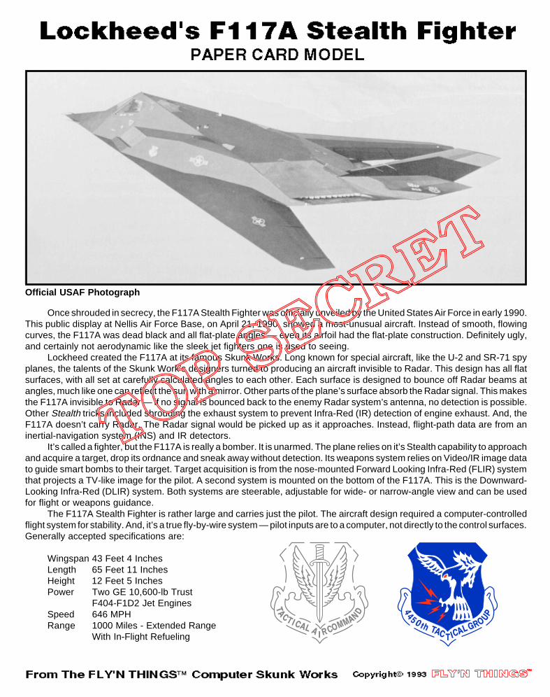
Once shrouded in secrecy, the F117A Stealth Fighter was officially unveiled by the United States Air Force in early 1990.This public display at Nellis Air Force Base, on April 21, 1990, showed a most-unusual aircraft. Instead of smooth, flowingcurves, the F117A was dead black and all flat-plate angles — even its airfoil had the flat-plate construction. Definitely ugly,and certainly not aerodynamic like the sleek jet fighters one is used to seeing.
Lockheed created the F117A at its famous Skunk Works. Long known for special aircraft, like the U-2 and SR-71 spyplanes, the talents of the Skunk Work’s designers turned to producing an aircraft invisible to Radar. This design has all flatsurfaces, with all set at carefully calculated angles to each other. Each surface is designed to bounce off Radar beams atangles, much like one can reflect the sun with a mirror. Other parts of the plane’s surface absorb the Radar signal. This makesthe F117A invisible to Radar — if no signal is bounced back to the enemy Radar system’s antenna, no detection is possible.Other Stealth tricks included shrouding the exhaust system to prevent Infra-Red (IR) detection of engine exhaust. And, theF117A doesn’t carry Radar. The Radar signal would be picked up as it approaches. Instead, flight-path data are from aninertial-navigation system (INS) and IR detectors.
It’s called a fighter, but the F117A is really a bomber. It is unarmed. The plane relies on it’s Stealth capability to approachand acquire a target, drop its ordnance and sneak away without detection. Its weapons system relies on Video/IR image datato guide smart bombs to their target. Target acquisition is from the nose-mounted Forward Looking Infra-Red (FLIR) systemthat projects a TV-like image for the pilot. A second system is mounted on the bottom of the F117A. This is the Downward-Looking Infra-Red (DLIR) system. Both systems are steerable, adjustable for wide- or narrow-angle view and can be usedfor flight or weapons guidance.
The F117A Stealth Fighter is rather large and carries just the pilot. The aircraft design required a computer-controlledflight system for stability. And, it’s a true fly-by-wire system — pilot inputs are to a computer, not directly to the control surfaces.Generally accepted specifications are:
Wingspan 43 Feet 4 InchesLength 65 Feet 11 InchesHeight 12 Feet 5 InchesPower Two GE 10,600-lb Trust
F404-F1D2 Jet EnginesSpeed 646 MPHRange 1000 Miles - Extended Range
With In-Flight Refueling
LEFT-SIDEJET INLETSHOWN
Cut Apart
Fold, Trim &Glue StripTo BackOf Seam
Fold, Trim &Glue StripTo BackOf Seam
NOSE-GEAR STRUT
NOSE-GEARDOOR MAIN-GEAR
STRUT
MAIN-GEARPRIMARY DOORS
13. 14.
15. 16.
17. 18.
Assemble The Side Jet Inlets ByGlueing Strips To The Back OfThe Cut-Open Slits. Fold The NosePiece Mark The Top On Back.
Glue The Nose Piece To The FrontOf The Fuelage. Add The Left- AndRight-Side Jet Air Inlets.
Fold Down On All Scored Lines.Fold Under The Glue Tabs. GlueThe Rear Tabs First. Then, GlueThe Tip And Bottom Tabs..
Finish By GlueingFin Assembly In Place.
Fold Landing-Gear Doors On ScoredLine And Glue. Fold Landing GearStruts Around A Toothpick And Glue.
Push Toothpick Of Landing-GearStruts Through Bottom And CenterSection Of Fuselage. Glue, Add Doors.
Fold Down On AllScored Lines. FoldUnder The Glue Tabs.
NOSE PIECE
Mark Back Of NosePiece With UP Arrow
Fold Under All Glue Tabs
Glue Tabs Nose Piece
Left-Side JetInlet Shown
Add Right-SideJet Inlet In TheSame PositionAs The Left Side
TAIL FIN ASSEMBLY Rear Glue Tabs
Tip Tabs
Fold UP
Tabs To GlueTo Fuselage
Bottom View
Completed Fin
FIN
Bottom Tab
MAIN LANDING GEAR STRUT NOSE GEAR STRUT
NOSE GEAR DOOR
PRIMARY MAINLANDING-GEAR DOOR
SECONDARYMAIN-GEAR DOOR
Glue Landing-GearStruts Around AToothpick Or AStraightned OutPaper Clip.
Left-Side View Of Aircraft
NOSE GEAR
Solid Part OfDoor On LeftSide Of Strut
Fold All Parts OnDashed Lines. GlueStruts To ToothpickAnd Doors To BottomOf Fuselage (Above).
Solid Part OfDoor BetweenMain Struts
Glue ToBack Of
MainStrut
Use A Black MarkingPen To Cover All Exposed Paper Edges.Add Landing Gear If Desired (Steps 17 And 18).
Copyright 1993
Official USAF Photograph

FOLD D
OWN A
ND GLU
E
FOLDDOWNTIPS &GLUE
FOLD D
OWN A
ND GLU
E
GLU
E
FOLD D
OWN A
ND GLU
E
FOLDDOWNTIPS &GLUE
FOLD D
OWN A
ND GLU
E
GLU
E
MAKE FOURPITOT TUBES
FROM TOOTHPICKS
CutApart
NO STEP
NO STEP
NO STEP
NO STEP
MSGT PHIL KOOPMAN
TSGT PETER WANK
BEND TABS UNDER ANDGLUE TO TOP OF WING
BEND TABS UNDERAND GLUE TO
FUSELAGE*SEE NOTE
BEND TABS UNDER ANDGLUE TO TOP OF WING
BEND TABS UNDER ANDGLUE TO FUSELAGE
*SEE NOTE
Cut Apart
Trim AndGlue StripTo BackOf Seam
Cut Apart Trim AndGlue StripTo BackOf Seam
CutApart
Trim AndGlue StripTo BackOf Seam
Trim AndGlue StripTo BackOf Seam
CutApart
*NOTE: Experienced Builders Can Remove The Top Tabs Of The Jet Inlets
DANGER
DANGER
BEND TABS UNDERAND GLUE TO FRONT
OF FUSELAGE
BEND TABS UNDERAND GLUE TO FRONTOF CENTER SECTION
TOP
MSGT PHIL KOOPMAN
TSGT PETER WANK
RIGHT SIDEJET INLET
LEFT SIDEJET INLET
NOSE GEAR & DOOR
NOSE"CONE"
WING PANELS
& BOTTOM
Lockheed F-117A Stealth Fighter
From The FLY'N THINGS™Computer Skunk Works
Copyright © 1993FLY'N THINGS™All Rights Reserved
Copyright © 1993 FLY'N THINGS™All Rights Reserved
FOLD UNDER
AND GLUE
FOLD UNDERAND GLUE
GLUE
FOLD UNDER AND GLUE
GLUE
FOLD TABS UNDERAND GLUE
FOLD ALL TABSUNDER AND
GLUE
Z-FOLDTABS
SIDE VIEWOF Z-FOLD
DANGER
DANGER
DANGER
DANGER
DANGER
NO STEP
DANGER
NO STEP
RESCUE
FOLD DOWN AND GLUE
FOLD DOWN AND GLUE
FOLD DOWNGLUE TABS
FOLD DOWN GLUE TABS
FUSELAGE CENTER SECTION
WING SUPPORT
WING SUPPORT
ASSEMBLY SEQUENCE:1. Glue Front Tabs To Bottom Of Fuselage. Make Sure The Center Section Is Centered. Hold Until Dry..2. DO NOT GLUE UNDERSIDE Of Wing Supports.3. Glue Rear Tabs Of Center Section. Pull Sides Of Fuselage Bottom Inward. Hold Wings And Center Section In Alignment Until Glue Is Dry -- Make Sure It Is Centered. 4. Glue Rear Tabs Of Fuselage Bottom. Slide Into Alignment With Back Of Center Section. Hold Until Dry.5. Glue Trailing-Edge Wing Tabs. Align, Hold Until dry. Then, Glue Wing Tip Tabs.6. NOTE: The Complex Geometry Of The F117A Is Computer Generated. Apparant Accuracy Can Be Off By Minor Errors In Scoring And Cutting. Trim To Fit At Wing Tips And Trailing Edge And At Back Of Fuselage Center Section.
DO NOT GLUE !
DO NOT GLUE!
BEND TABUNDER AND GLUE
BEND TABUNDER AND
GLUE TOFUSELAGE
BEND TABUNDER AND GLUE
BEND TABUNDER AND GLUE
BEND TABUNDER AND
GLUE TOFUSELAGE
BEND TABUNDER AND GLUE
FoldUp
BEND TAB UNDER AND GLUE
BEND TAB UNDER AND GLUE
USAF
802USAF802
Trim And Glue StripTo Back Of Seams
Stiffen Three Top Seams To Prevent "Oil Can" Bending
Fold,Trim and
Glue StripTo BackOf Seam
CutApart
Trim And Glue StripTo Back Of Seams
MAIN LANDING GEAR
MAIN GEAR DOORS
TOP OF FUSELAGE
FINS
Lockheed F-117A Stealth FighterFrom The FLY'N THINGS
Computer Skunk Works
Copyright © 1993 FLY'N THINGS™ All Rights Reserved

7. 8.From The Printed Side, Fold DownOn All Dashed Lines You Scored.Turn Over, Then ...
Fold Down All Tabs On The CenterSection. Read Assembly Instructions!
Wing PanelsAnd Bottom
Shown PrintedSide Down
Pinch Folds
Fold DownAt Wing Root
Pinch Fold
Read The Assembly
Instructions Printed
On Center SectionFold Down
All Tabs
Nose Tabs Wing Support
Side Tabs
11 Inches
17 Inch
es
Two Layers OfHeavy Cardboard,Taped Togather AroundAll Of The Edges.
Tape
Single-EdgeRazor Blade
Scissors
White Glue OrHouseholdCement
Metal-EdgeRuler Or
Score Folds With A Fine-Line Black
Ball-Point Pen2. AND, Tape And A
Cutting Board:1. You WillNeed:
Lockheed F-117A StealthBuilding Instructions
Glue StripTo BackOf Seam
Rear-Side Tabs
Front Tab
DO NOT GLUE
Z-FoldedUnder
Fold AllBottomTabs Under
Assemble Fuselage Top. Glue FrontTab First. Pull Rear Seam TogatherAnd Glue Stiffener Underneath. Then,Glue Rear-Side Tabs.
9. 10.Glue The Center Section To TheBottom. Glue Nose, Wing Suppports,Sides And Rear Bottom Tabs.
Read The Assembly
Instructions Printed
On Center Section
Wing PanelsAnd Bottom
Shown PrintedSide Down
After Center Section IsDry, Fold Over Wing Panels And Glue TabsAt Trailing Edge. Then,Glue Tabs At Wing Tips.
Fold UP All WingAnd Tip Tabs. Glue
Wing Tabs First
Then, GlueWing Tips
Fold Wings UPAlong This Line
Fold Stiffener Along CenterLine. Then Trim To Final Size
3.
FOLD UNDER
AND GLUE
RESCUE
BEND
TAB
UN
DER
AND
GLU
E
Or Model Knife Straight Edge
Score Along All Dashed Lines Of BothSheets With A Fine-Line Black Ball-PointPen Or A Smooth-Edge Butter Knife.
NEXT, Cut Along The Ends Of TheAssembly Tabs With A Model Knife.4.
Trim AndGlue StripsTo BackOf Seams
Next, Stiffen The Three TopFolds Of The Fuselage ToPrevent Bending.
11. 12. Glue Completed Fuselage TopTo The Bottom/Wing Assembly.
Fold Stiffeners Along CenterLine. Then Trim To Final Size
Align Top SlotTo Wing L.E.
Glue FrontTabs First
Glue Side-PanelTabs Next
Then GlueAnd SlideUnder TheZ-Fold Tabs
Push Down On Fuselage Top, Slightly Spreading ItTo Align With Wing Top Surface And Fuselage Bottom
Finish With Rear Tabs
5. 6.
E
GLUE
DANGER
DANGER
ERNO STEP
DANGER
AND, Cut Open AllV-Slits On FuselageAnd Jet Inlets.
Make Straight CutsAlong Both LinesMarked Cut Apart.
THEN, Cut Along The Black OutlinesBetween Tab Cuts. Finish By CuttingParts Free Along Remaining Outlines.
Dashed-Line ArrowsAre Prior Tab Cuts
GLUDANG
Copyright © 1993 FLY'N THINGS™ All Rights ReservedCopyright © 1993 FLY'N THINGS™ All Rights Reserved

3.
5. 6.
FOLD UNDER
AND GLUE
RESCUE
11 Inches
17 Inch
es
GLUE
GLUE
DANGER
DANGER
DANGERNO STEP
DANGER
BEND
TAB
UN
DER
AND
GLU
E
Two Layers OfHeavy Cardboard,Taped Togather AroundAll Of The Edges.
Tape
Single-EdgeRazor Blade
Or Model Knife
Scissors
White Glue OrHouseholdCement
Metal-EdgeRuler Or
Straight Edge
Score Folds With A Fine-Line Black
Ball-Point Pen2. AND, Tape And A
Cutting Board:1. You WillNeed:
Score Along All Dashed Lines Of BothSheets With A Fine-Line Black Ball-PointPen Or A Smooth-Edge Butter Knife.
NEXT, Cut Along The Ends Of TheAssembly Tabs With A Model Knife.
AND, Cut Open AllV-Slits On FuselageAnd Jet Inlets.
Make Straight CutsAlong Both LinesMarked Cut Apart.
THEN, Cut Along The Black OutlinesBetween Tab Cuts. Finish By CuttingParts Free Along Remaining Outlines.
Dashed-Line ArrowsAre Prior Tab Cuts
Lockheed F-117A StealthBuilding Instructions
4.
Copyright © 1993 FLY'N THINGS™ All Rights Reserved
7. 8.From The Printed Side, Fold DownOn All Dashed Lines You Scored.Turn Over, Then ...
Fold Down All Tabs On The CenterSection. Read Assembly Instructions!
Wing PanelsAnd Bottom
Shown PrintedSide Down
Pinch Folds
Fold DownAt Wing Root
Pinch Fold
Read The Assembly
Instructions Printed
On Center SectionFold Down
All Tabs
Nose Tabs Wing Support
Side Tabs
Glue StripTo BackOf Seam
Rear-Side Tabs
Front Tab
Z-FoldedUnder
Fold AllBottomTabs Under
Assemble Fuselage Top. Glue FrontTab First. Pull Rear Seam TogatherAnd Glue Stiffener Underneath. Then,Glue Rear-Side Tabs.
9. 10.Glue The Center Section To TheBottom. Glue Nose, Wing Suppports,Sides And Rear Bottom Tabs.
Read The Assembly
Instructions Printed
On Center Section
Wing PanelsAnd Bottom
Shown Printed
After Center Section IsDry, Fold Over Wing Panels And Glue TabsAt Trailing Edge. Then,Glue Tabs At Wing Tips.
Fold UP All WingAnd Tip Tabs. Glue
Wing Tabs First
Then, GlueWing Tips
Fold Wings UPAlong This Line
Fold Stiffener Along CenterLine. Then Trim To Final Size
DO NOT GLUE
Trim AndGlue StripsTo BackOf Seams
Next, Stiffen The Three TopFolds Of The Fuselage ToPrevent Bending.
11. 12. Glue Completed Fuselage TopTo The Bottom/Wing Assembly.
Side Down
Fold Stiffeners Along CenterLine. Then Trim To Final Size
Align Top SlotTo Wing L.E.
Glue FrontTabs First
Glue Side-PanelTabs Next
Then GlueAnd SlideUnder TheZ-Fold Tabs
Push Down On Fuselage Top, Slightly Spreading ItTo Align With Wing Top Surface And Fuselage Bottom
Finish With Rear Tabs
Copyright © 1993 FLY'N THINGS™ All Rights Reserved

LEFT-SIDEJET INLETSHOWN
Cut Apart
Fold, Trim &Glue StripTo BackOf Seam
Fold, Trim &Glue StripTo BackOf Seam
13. 14.Assemble The Side Jet Inlets ByGlueing Strips To The Back OfThe Cut-Open Slits. Fold The NosePiece Mark The Top On Back.
Glue The Nose Piece To The FrontOf The Fuelage. Add The Left- AndRight-Side Jet Air Inlets.
Fold Down On AllScored Lines. FoldUnder The Glue Tabs.
NOSE PIECE
Mark Back Of NosePiece With UP Arrow
Fold Under All Glue Tabs
Glue Tabs Nose Piece
Left-Side JetInlet Shown
Add Right-SideJet Inlet In TheSame PositionAs The Left Side
Once shrouded in secrecy, the F117A Stealth Fighter was officially unveiled by the United States Air Force in early 1990.This public display at Nellis Air Force Base, on April 21, 1990, showed a most-unusual aircraft. Instead of smooth, flowingcurves, the F117A was dead black and all flat-plate angles — even its airfoil had the flat-plate construction. Definitely ugly,and certainly not aerodynamic like the sleek jet fighters one is used to seeing.
Lockheed created the F117A at its famous Skunk Works. Long known for special aircraft, like the U-2 and SR-71 spyplanes, the talents of the Skunk Work’s designers turned to producing an aircraft invisible to Radar. This design has all flatsurfaces, with all set at carefully calculated angles to each other. Each surface is designed to bounce off Radar beams atangles, much like one can reflect the sun with a mirror. Other parts of the plane’s surface absorb the Radar signal. This makesthe F117A invisible to Radar — if no signal is bounced back to the enemy Radar system’s antenna, no detection is possible.Other Stealth tricks included shrouding the exhaust system to prevent Infra-Red (IR) detection of engine exhaust. And, theF117A doesn’t carry Radar. The Radar signal would be picked up as it approaches. Instead, flight-path data are from aninertial-navigation system (INS) and IR detectors.
It’s called a fighter, but the F117A is really a bomber. It is unarmed. The plane relies on it’s Stealth capability to approach
Official USAF Photograph
15. 16.Fold Down On All Scored Lines.Fold Under The Glue Tabs. GlueThe Rear Tabs First. Then, GlueThe Tip And Bottom Tabs..
Finish By GlueingFin Assembly In Place.
TAIL FIN ASSEMBLY Rear Glue Tabs
Tip Tabs
Fold UP
Tabs To GlueTo Fuselage
Bottom View
Completed Fin
FIN
Bottom TabUse A Black MarkingPen To Cover All Exposed Paper Edges.Add Landing Gear If Desired (Steps 17 And 18).
and acquire a target, drop its ordnance and sneak away without detection. Its weapons system relies on Video/IR image datato guide smart bombs to their target. Target acquisition is from the nose-mounted Forward Looking Infra-Red (FLIR) systemthat projects a TV-like image for the pilot. A second system is mounted on the bottom of the F117A. This is the Downward-Looking Infra-Red (DLIR) system. Both systems are steerable, adjustable for wide- or narrow-angle view and can be usedfor flight or weapons guidance.
The F117A Stealth Fighter is rather large and carries just the pilot. The aircraft design required a computer-controlledflight system for stability. And, it’s a true fly-by-wire system — pilot inputs are to a computer, not directly to the control surfaces.Generally accepted specifications are:
Wingspan 43 Feet 4 InchesLength 65 Feet 11 InchesHeight 12 Feet 5 InchesPower Two GE 10,600-lb Trust
F404-F1D2 Jet EnginesSpeed 646 MPHRange 1000 Miles - Extended Range
With In-Flight Refueling
NOSE-GEAR STRUT
NOSE-GEARDOOR MAIN-GEAR
STRUT
MAIN-GEARPRIMARY DOORS
17. 18.Fold Landing-Gear Doors On ScoredLine And Glue. Fold Landing GearStruts Around A Toothpick And Glue.
Push Toothpick Of Landing-GearStruts Through Bottom And CenterSection Of Fuselage. Glue, Add Doors.
MAIN LANDING GEAR STRUT NOSE GEAR STRUT
NOSE GEAR DOOR
PRIMARY MAINLANDING-GEAR DOOR
SECONDARYMAIN-GEAR DOOR
Glue Landing-GearStruts Around AToothpick Or AStraightned OutPaper Clip.
Left-Side View Of Aircraft
NOSE GEAR
Solid Part OfDoor On LeftSide Of Strut
Fold All Parts OnDashed Lines. GlueStruts To ToothpickAnd Doors To BottomOf Fuselage (Above).
Solid Part OfDoor BetweenMain Struts
Glue ToBack Of
MainStrut
Copyright 1993