Embed Size (px)
Citation preview

Q87H3-M6 USER MANUAL
PrefaceCopyrightThis publication, including all photographs, illustrations and software, is protectedunder international copyright laws, with all rights reserved. Neither this manual, norany of the material contained herein, may be reproduced without written consent ofthe author.
Version 1.0
DisclaimerThe information in this document is subject to change without notice. The manufac-turer makes no representations or warranties with respect to the contents hereofand specifically disclaims any implied warranties of merchantability or fitness forany particular purpose. The manufacturer reserves the right to revise this publica-tion and to make changes from time to time in the content hereof without obligationof the manufacturer to notify any person of such revision or changes.
Trademark RecognitionMicrosoft, MS-DOS and Windows are registered trademarks of Microsoft Corp.
MMX, Pentium, Pentium-II, Pentium-III, Celeron are registered trademarks of IntelCorporation.
Other product names used in this manual are the properties of their respective ownersand are acknowledged.
Federal Communications Commission (FCC)This equipment has been tested and found to comply with the limits for a Class Bdigital device, pursuant to Part 15 of the FCC Rules. These limits are designed toprovide reasonable protection against harmful interference in a residential instal-lation. This equipment generates, uses, and can radiate radio frequency energy and,if not installed and used in accordance with the instructions, may cause harmfulinterference to radio communications. However, there is no guarantee that interfer-ence will not occur in a particular installation. If this equipment does cause harmfulinterference to radio or television reception, which can be determined by turningthe equipment off and on, the user is encouraged to try to correct the interference byone or more of the following measures:
• Reorient or relocate the receiving antenna• Increase the separation between the equipment and the receiver• Connect the equipment onto an outlet on a circuit different from that to
which the receiver is connected• Consult the dealer or an experienced radio/TV technician for help
Shielded interconnect cables and a shielded AC power cable must be employed withthis equipment to ensure compliance with the pertinent RF emission limits govern-ing this device. Changes or modifications not expressly approved by the system’smanufacturer could void the user’s authority to operate the equipment.

iiQ87H3-M6 USER MANUAL
Declaration of ConformityThis device complies with part 15 of the FCC rules. Operation is subject to the follow-ing conditions:
• This device may not cause harmful interference.• This device must accept any interference received, including interference
that may cause undesired operation.
Canadian Department of CommunicationsThis class B digital apparatus meets all requirements of the Canadian Interference-causing Equipment Regulations.Cet appareil numérique de la classe B respecte toutes les exigences du Réglementsur le matériel brouilieur du Canada.
The manual consists of the following:
Describes features of themotherboard.
page 1
Describes installation ofmotherboard components.
page 7
page 27
Installing the Motherboard
Introducing the Motherboard
Provides information on us-ing the BIOS Setup Utility.
Limits and methods of mesurement of radio disturbance char-acteristics of information technology equipment
EN 55022
EN 61000-3-2 Disturbances in supply systems caused
EN 61000-3-3 Disturbances in supply systems caused by household appli-ances and similar electrical equipment “ Voltage fluctuations”
EN 55024 Information technology equipment-Immunity characteristics-Limits and methods of measurement
EN 60950 Safety for information technology equipment including electri-cal business equipment
CE marking
About the Manual
This device is in conformity with the following EC/EMC directives:
Chapter 1
Chapter 2
Chapter 3Using BIOS
Chapter 5Trouble Shooting
Provides basic troubleshooting tips.
page 53
Chapter 4 page 47Intel® Matrix Storage ManagerRAID Configurations
Describes Intel® MatrixStorage Manager RAIDConfigurations.

iiiQ87H3-M6 USER MANUAL
Chapter 2 7Installing the Motherboard 7
Safety Precautions..............................................................................7Installing the Motherboard in a Chassis.......................................7Checking Jumper Settings..................................................................8Installing Hardware...........................................................................9
Installing the Processor............................................................9Installing the CPU Cooler........................................................11Installing Memory Modules...................................................12Installing Add-on Cards..........................................................14Connecting Optional Devices.................................................16Installing a SATA Hard Drive...................................................22
Connecting Case Components........................................................23Front Panel Header................................................................25
TABLE OF CONTENTS
Preface i
Chapter 1 1Introducing the Motherboard 1
Introduction...........................................................................................1Pakage Contents..................................................................................1Specifications......................................................................................2Motherboard Components................................................................4I/O Ports...............................................................................................6
Chapter 3 27Using BIOS 27
About the Setup Utility......................................................................27The Standard Configuration........................ ...........................27Entering the Setup Utility.......................................................27
Using BIOS.........................................................................................28BIOS Navigation Keys..............................................................29Main Menu.............................................................................30Advanced Menu......................................................................31Power Menu............................................................................39Authentication Menu..............................................................41Security Menu.........................................................................42Boot Options Menu.................................................................44Exit Menu...............................................................................45Updating the BIOS......................................................................46

ivQ87H3-M6 USER MANUAL
Chapter 5 53Trouble Shooting 53
Start up problems during assembly..............................................53Start up problems after prolong use............................................54Maintenance and care tips..............................................................54Basic Troubleshooting Flowchart.....................................................55
Chapter 4 47Intel®®®®® Matrix Storage Manager RAID Configuration 47
Before creating a RAID set..............................................................47Entering Intel® Matrix Storage Manager RAID BIOS utility.....48Creating a RAID set...........................................................................49Deleting a RAID set...........................................................................51Reseting disks to Non-RAID............................................................52Exiting Setup.....................................................................................52

1Q87H3-M6 USER MANUAL
Cha
pter
1Chapter 1Introducing the Motherboard
Introduction
Your motherboard package ships with the following items:
Package Contents
Q87H3-M6 MotherboardQuick Installation GuideUser ManualDVDI/O Shield2 SATA Cables
The package contents above are for reference only, please take the actualpackage items as standard.
Thank you for choosing the Q87H3-M6 motherboard. This motherboard is a high per-formance, enhanced function motherboard designed to support the LGA1150 socketfor Intel 4th Generation CoreTM Family processors for high-end business or personaldesktop markets.
This motherboard is based on Intel® Q87 Chipset for best desktop platform solution.It supports up to 32 GB of system memory with dual channel DDR3 1600/1333 MHz.One PCI Express x16 Gen3 slot and one PCI Express x16 Gen2(with x4 connectivity)are supported , intended for Graphics Interface. In addition, one PCI Express x1 slotand one PCI slot are for extending usage.
It integrates USB 2.0 and USB 3.0 interface, supporting up to seven USB 2.0 ports(twoUSB 2.0 ports at rear panel, two USB 2.0 headers support additional four USB 2.0ports and one 5-pin USB 2.0 header supports one USB 2.0 ports) and six USB 3.0ports(four USB 3.0 ports at rear panel and one USB 3.0 header supports two USB 3.0ports).
The motherboard is equipped with advanced full set of I/O ports in the rear panel,including PS/2 mouse and PS/2 keyboard connectors, one Display port (DP), one HDMIport, one D-sub (VGA) port, one DVI port, four USB 3.0 ports, one LAN port, two USB 2.0ports, and audio jacks for line-in, line-out and microphone.
In addition, this motherboard supports five SATA 6.0Gb/s connectors.

Chapter 1
2Q87H3-M6 USER MANUAL
CPU
Specifications
• Intel® Q87 ChipsetChipset
• Dual-channel DDR3 memory architecture• 4 x 240-pin DDR3 DIMM sockets support up to 32 GB• Supports DDR3 1600/1333 MHz
Memory
• 1 x PCI Express x16 Gen3 slot• 1 x PCI Express x16 Gen2(with x4 connectivity) slot• 1 x PCI Express x1 slot• 1 x PCI slot
• Supported by Intel® Q87 Express Chipset - 5 x Serial ATA 6.0 Gb/s devices - RAID 0, RAID 1, RAID 5, RAID 10 Configuration
ExpansionSlots
Storage
• 1 x PS/2 keyboard & PS/2 mouse connectors• 1 x Display port(DP)• 1 x HDMI port• 1 x D-sub port(VGA)• 1 x DVI port• 4 x USB 3.0 ports• 1 x RJ45 LAN connector• 2 x USB 2.0 ports• 1 x Audio port (Line in, line out and microphone)
Rear Panel I/O
LAN • Intel® WGI217LM
• Realtek ALC662 6-Ch HD audio CODECAudio
• LGA1150 socket for Intel 4th Generation CoreTM Family processors
• 1 x 24-pin ATX Power Supply connector• 1 x 4-pin ATX_12V Power Supply connector• 1 x 4-pin CPU_FAN connector• 1 x 4-pin SYS_FAN connector• 5 x SATA III 6.0Gb/s connectors• 1 x Front panel switch/LED header• 1 x Front panel audio header• 2 x USB 2.0 headers support additional four USB 2.0 ports• 1 x 5-pin USB 2.0 header supports additional one USB 2.0 port• 1 x USB 3.0 header supports additional two USB 3.0 ports• 2 x Onboard Serial port headers (COM)• 1 x Clear CMOS header with jumper• 1 x Onboard parallel port header (LPT)• 1 x Buzzer• 1 x Case open header
Internal I/OConnectors &Headers
3Q87H3-M6 USER MANUAL
Cha
pter
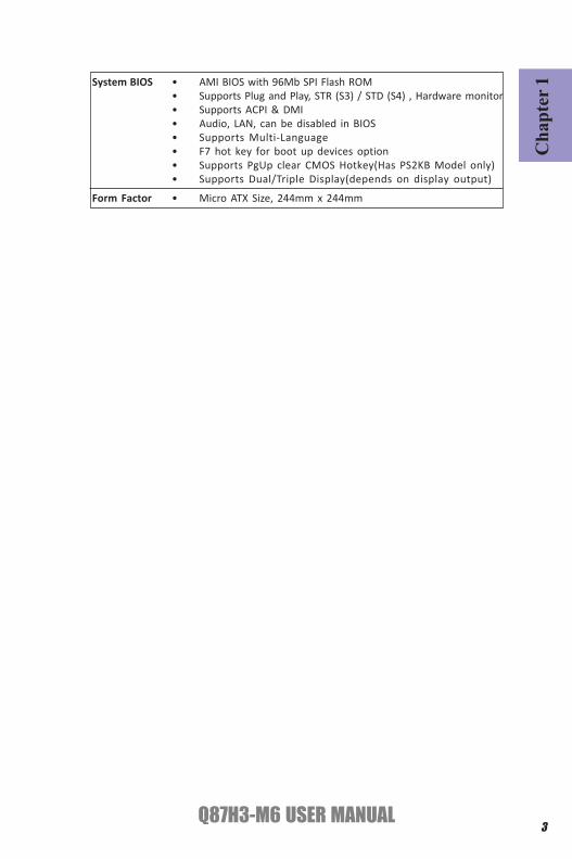
1• AMI BIOS with 96Mb SPI Flash ROM• Supports Plug and Play, STR (S3) / STD (S4) , Hardware monitor• Supports ACPI & DMI• Audio, LAN, can be disabled in BIOS• Supports Multi-Language• F7 hot key for boot up devices option• Supports PgUp clear CMOS Hotkey(Has PS2KB Model only)• Supports Dual/Triple Display(depends on display output)
System BIOS
Form Factor • Micro ATX Size, 244mm x 244mm
Chapter 1
4Q87H3-M6 USER MANUAL
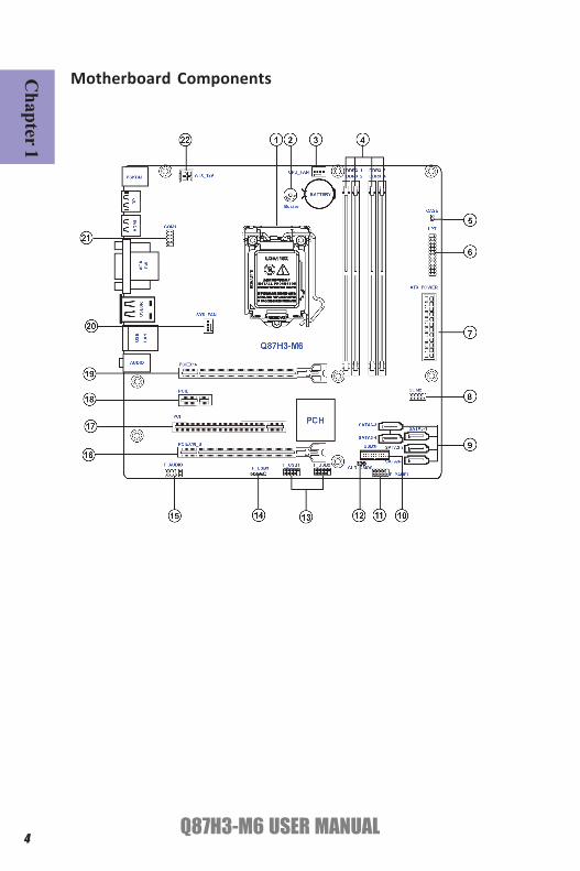
Motherboard Components

5Q87H3-M6 USER MANUAL
Cha
pter
1Table of Motherboard Components
LABEL COMPONENTS1. CPU Supports the LGA1150 socket for 4th Generation
CoreTM Family Processors2. Buzzer Buzzer3. CPU_FAN CPU cooling fan connector4. DDR3_1~4 240-Pin DDR3 long DIMM slots
(Channel A: DIMM1~2 Channel B: DIMM3~4) 5. CASE Case open header6. LPT Onboard parallel port header7. ATX_POWER Standard 24-pin ATX power connector8. COM2 Onboard serial port header9. SATA3_1~5 Serial ATA 6.0Gb/s connectors10. USB3F Front panel USB 3.0 connector11. F_PANEL Front panel switch/LED header12. CLR_CMOS Clear CMOS header with jumper 13. F_USB1~2 Front panel USB 2.0 headers14. F_USB3 Front panel USB 2.0 header15. F_AUDIO Front panel audio header16. PCIEX16_S PCI Express x16 slot (runs at X4 mode)17. PCI 32-bit add-on card slot18. PCIE PCI Express x1 slot19. PCIEX16 PCI Express x16 slot20. SYS_FAN System cooling fan connector 21. COM1 Onboard serial port header22. ATX_12V Auxiliary 4-pin power connector

Chapter 1
6Q87H3-M6 USER MANUAL
I/O Ports
1. PS/2 MouseUse the upper PS/2 port to connect the PS/2 Mouse.
2. PS/2 KeyboardUse the lower PS/2 port to connect the PS/2 Keyboard.
Link LED
LAN Port
9. USB 2.0 PortsUse the USB 2.0 ports to connect USB 2.0 devices.
10. Line-in (blue)It can be connected to an external CD/DVD player, Tape player or other audiodevices for audio input.
11. Line-out (green)It is used to connect to speakers or headphones.
12. Microphone (pink)It is used to connect to a microphone.
TransmissionSpeed
LAN LED Status Description
OFF No dataOrange blinking ActiveOFF No linkGreen LinkOFF No dataOrange blinking ActiveOFF No linkGreen Link
Activity LED
Link LED100M
GigaActivity LED
Link LED
4. HDMI PortYou can connect the display device to the HDMI port.
3. Display Port (DP)You can connect the display device to the display port.
6. DVI PortConnect your monitor to the DVI port.
5. VGA PortConnect your monitor to the VGA port.
7. USB 3.0 PortsUse the USB 3.0 ports to connect USB 3.0 devices.8. LAN PortConnect an RJ-45 jack to the LAN port to connect your computer to the Network.

Cha
pter
2
7Q87H3-M6 USER MANUAL
Chapter 2Installing the Motherboard
2-1. Safety Precautions
2-2. Installing the motherboard in a ChassisThis motherboard carries a Micro ATX form factor of 244 x 244 mm. Choose a chassisthat accommodates this form factor. Make sure that the I/O template in the chassismatches the I/O ports installed on the rear edge of the motherboard. Most systemchassis have mounting brackets installed in the chassis, which corresponds to theholes in the motherboard. Place the motherboard over the mounting brackets andsecure the motherboard onto the mounting brackets with screws.
Follow these safety precautions when installing the motherboard:
• Wear a grounding strap attached to a grounded device to avoid damagefrom static electricity.
• Discharge static electricity by touching the metal case of a safely groundedobject before working on the motherboard.
• Leave components in the static-proof bags.• Always remove the AC power by unplugging the power cord from the power
outlet before installing or removing the motherboard or other hardwarecomponents.
Do not over-tighten the screws as this can stress the motherboard.

Chapter 2
8Q87H3-M6 USER MANUAL
The following illustration shows the location of the motherboard jumpers. Pin 1 islabeled.
To avoid the system instability after clearing CMOS, we recommend users toenter the main BIOS setting page to “Load Default Settings” and then “Saveand Exit Setup”.
2-3. Checking Jumper Settings
Cha
pter
2
9Q87H3-M6 USER MANUAL
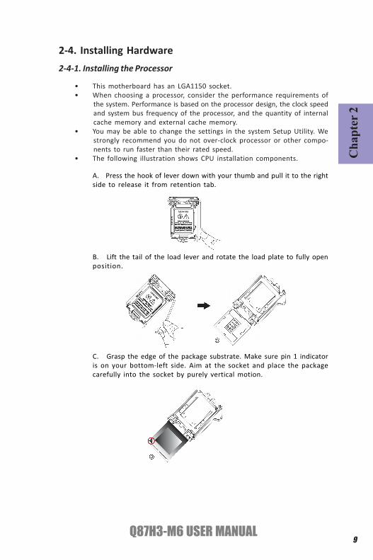
2-4. Installing Hardware2-4-1. Installing the Processor
• This motherboard has an LGA1150 socket.• When choosing a processor, consider the performance requirements of
the system. Performance is based on the processor design, the clock speedand system bus frequency of the processor, and the quantity of internalcache memory and external cache memory.
• You may be able to change the settings in the system Setup Utility. Westrongly recommend you do not over-clock processor or other compo-nents to run faster than their rated speed.
• The following illustration shows CPU installation components.
A. Press the hook of lever down with your thumb and pull it to the rightside to release it from retention tab.
B. Lift the tail of the load lever and rotate the load plate to fully openposition.
C. Grasp the edge of the package substrate. Make sure pin 1 indicatoris on your bottom-left side. Aim at the socket and place the packagecarefully into the socket by purely vertical motion.

Chapter 2
10Q87H3-M6 USER MANUAL
D. Rotate the load plate onto the package IHS (Intergraded HeatSpreader). Engage the load lever while pressing down lightly onto theload plate. Secure the load lever with the hook under retention tab. Thenthe cover will flick automatically.
Please save and replace the cover onto the CPU socket if processor is re-moved.

Cha
pter
2
11Q87H3-M6 USER MANUAL
A. Apply some thermal grease onto the contacted area between theheatsink and the CPU, and make it to be a thin layer.
B. Fasten the cooling fan supporting base onto the CPU socket on themotherboard. And make sure the CPU fan is plugged to the CPU fanconnector.
C. Connect the CPU cooler power connector to the CPU_FAN connector.
2-4-2. Installing the CPU Cooler• Install the cooling fan in a well-lit work area so that you can clearly see the
motherboard and processor socket.• Avoid using cooling fans with sharp edges in case the fan casing and the
clips cause serious damage to the motherboard or its components.• To achieve better airflow rates and heat dissipation, we suggest that you
use a high quality fan with 3800 rpm at least. CPU fan and heat sink instal-lation procedures may vary with the type of CPU fan/heatsink supplied.The form and size of fan/heatsink may also vary.
• DO NOT remove the CPU cap from the socket before installing a CPU.• Return Material Authorization (RMA) requests will be accepted only if the
motherboard comes with the cap on the LGA1150 socket.• The following illustration shows how to install CPU fan.

Chapter 2
12Q87H3-M6 USER MANUAL
2-4-3. Installing Memory Modules• This motherboard accommodates four memory modules. It can support
four 240-pin DDR3 1600/1333.• Do not remove any memory module from its antistatic packaging until
you are ready to install it on the motherboard. Handle the modules onlyby their edges. Do not touch the components or metal parts. Always weara grounding strap when you handle the modules.
• You must install at least one module in any of the four slots. Total memorycapacity is 32 GB.
• Refer to the following to install the memory modules.
C. The slot latches are levered upwards and latch on to the edges of theDIMM.
A. Push the latches on each side of the DIMM slot down.
B. Install the DIMM module into the slot and press it firmly down until itfits in place correctly. Check that the cutouts on the DIMM module edgeconnector match the notches in the DIMM slot.
The four DDR3 memory sockets (DDR3_1, DDR3_2, DDR3_3 and DDR3_4) are dividedinto two channels and each channel has two memory sockets as following:
Channel A: DDR3_1, DDR3_2Channel B: DDR3_3, DDR3_4

Cha
pter
2
13Q87H3-M6 USER MANUAL
Recommend memory configuration
Model Sockets
DDR3_1 DDR3_2 DDR3_3 DDR3_4 1 DIMM ~ Populated ~ ~
1 DIMM ~ ~ ~ Populated
2 DIMMs ~ Populated ~ Populated
3 DIMMs Populated Populated ~ Populated
3 DIMMs ~ Populated Populated Populated
4 DIMMs Populated Populated Populated Populated
Due to Intel CPU spec definition, please follow the table above forrecommended memory configuration.
1. For best performance and compatibility, we recommend that users givepriority to the white DIMMs (DDR3_2/DDR3_4) when installing DIMMs.2. We suggest users not to mix memory type. It is recommended to use thesame brand and type memory on this motherboard.
Chapter 2
14Q87H3-M6 USER MANUAL
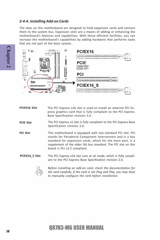
2-4-4. Installing Add-on Cards
The slots on this motherboard are designed to hold expansion cards and connectthem to the system bus. Expansion slots are a means of adding or enhancing themotherboard’s features and capabilities. With these efficient facilities, you canincrease the motherboard’s capabilities by adding hardware that performs tasksthat are not part of the basic system.
PCIEX16 Slot The PCI Express x16 slot is used to install an external PCI Ex-press graphics card that is fully compliant to the PCI ExpressBase Specification revision 3.0.
This motherboard is equipped with one standard PCI slot. PCIstands for Peripheral Component Interconnect and is a busstandard for expansion cards, which for the most part, is asupplement of the older ISA bus standard. The PCI slot on thisboard is PCI v2.2 compliant.
PCI Slot
Before installing an add-on card, check the documentation forthe card carefully. If the card is not Plug and Play, you may haveto manually configure the card before installation.
The PCI Express x1 slot is fully compliant to the PCI Express BaseSpecification revision 2.0.
PCIE Slot
PCIEX16_S Slot The PCI Express x16 slot runs at x4 mode, which is fully compli-ant to the PCI Express Base Specification revision 2.0.

Cha
pter
2
15Q87H3-M6 USER MANUAL
Install the VGA Card in the PCIE X16 slot
1 Remove a blanking plate from the system case corresponding to the slotyou are going to use.
2 Install the edge connector of the add-on card into the expansion slot.Ensure that the edge connector is correctly seated in the slot.
3 Secure the metal bracket of the card to the system case with a screw.
1. For some add-on cards, for example graphics adapters and network adapt-ers, you have to install drivers and software before you can begin using theadd-on card.
2. The onboard PCI interface does not support 64-bit SCSI cards.
Follow these instructions to install an add-on card:
Please refer to the following illustrations to install the add-on card:
Install the VGA Card in the PCI slot Install the LAN Card in the PCIE X1 slot

Chapter 2
16Q87H3-M6 USER MANUAL
2-4-5. Connecting Optional DevicesRefer to the following for information on connecting the motherboard’s optionaldevices:
No. Components No. Components
1 CASE 5 USB3F
2 LPT 6 F_USB1~2&F_USB3
3 COM1~2 7 F_AUDIO
4 SATA3_1~5 ~~ ~~

Cha
pter
2
17Q87H3-M6 USER MANUAL
This is a header that can be used to connect to the printer, scanner or other devices.
2. LPT: Onboard parallel port header
1. CASE: Chassis Intrusion Detect HeaderThis detects if the chassis cover has been removed. This function needs a chassisequipped with instrusion detection switch and needs to be enabled in BIOS.

Chapter 2
18Q87H3-M6 USER MANUAL
SATA3_1~5 connectors are used to support the Serial ATA 6.0Gb/s device, simplerdisk drive cabling and easier PC assembly. It eliminates limitations of the currentParallel ATA interface. But maintains register compatibility and software compat-ibility with Parallel ATA.
4. SATA3_1~5: Serial ATA connectors
3. COM: Onboard serial port header
Connect a serial port extension bracket to this header to add a serial port to yoursystem.

Cha
pter
2
19Q87H3-M6 USER MANUAL
Please make sure that the USB cable has the same pin assignment as indi-cated above. A different pin assignment may cause damage or system hang-up.
This Motherboard implements one USB 3.0 header supporting 2 extra front USB 3.0ports, which delivers 5Gb/s transfer rate.
5. USB3F: Front Panel USB 3.0 header
The motherboard has three USB 2.0 headers supporting five USB 2.0 ports. 5-pinF_USB3 supports one USB 2.0 device.Additionally, some computer cases have USBports at the front of the case. If you have this kind of case, use auxiliary USB connec-tor to connect the front-mounted ports to the motherboard.
6. F_USB1~3: Front Panel USB 2.0 headers
Please make sure that the USB cable has the same pin assignment as indi-cated above. A different pin assignment may cause damage or system hang-up.

Chapter 2
20Q87H3-M6 USER MANUAL
The front panel audio header allows the user to install auxiliary front-oriented mi-crophone and line-out ports for easier access. This header supports HD audio bydefault. If you want connect an AC’ 97 front panel audio to HD onboard headers,please set as below picture.
7. F_AUDIO: Front Panel Audio Header
If you use AC’ 97 Front Panel, please tick off the option of “Disabled Front PanelDetect ”. If you use HD Audio Front Panel, please don’ t tick off “Disabled Front PanelDetect ” .
* For reference only
AC’ 97 Audio Configuration: To enable the front panel audio connector to sup-port AC97 Audio mode.
Cha
pter
2
21Q87H3-M6 USER MANUAL
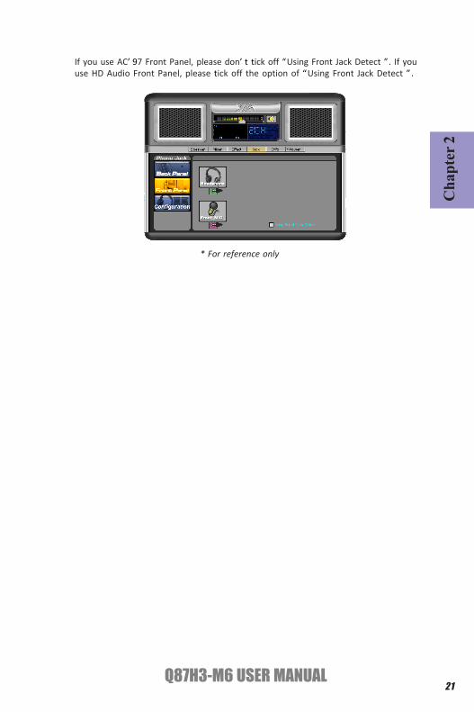
If you use AC’ 97 Front Panel, please don’ t tick off “Using Front Jack Detect ”. If youuse HD Audio Front Panel, please tick off the option of “Using Front Jack Detect ”.
* For reference only

Chapter 2
22Q87H3-M6 USER MANUAL
2-4-6. Installing a SATA Hard Drive
About SATA ConnectorsYour motherboard features Six SATA connectors supporting a total of six drives. SATArefers to Serial ATA (Advanced Technology Attachment) is the standard interface forthe IDE hard drives which are currently used in most PCs. These connectors are welldesigned and will only fit in one orientation. Locate the SATA connectors on themotherboard and follow the illustration below to install the SATA hard drives.
To install the Serial ATA (SATA) hard drives, use the SATA cable that supports the SerialATA protocol. This SATA cable comes with a SATA power cable. You can connect eitherend of the SATA cable to the SATA hard drive or the connector on the motherboard.
Refer to the illustration below for proper installation:
1 Attach either cable end to the connector on the motherboard.2 Attach the other cable end to the SATA hard drive.3 Attach the SATA power cable to the SATA hard drive and connect the other
end to the power supply.
* For reference only
Installing Serial ATA Hard Drives
This section describes how to install a SATA Hard Drive.

Cha
pter
2
23Q87H3-M6 USER MANUAL
After you have installed the motherboard into a case, you can begin connecting themotherboard components. Refer to the following:
2-4-7. Connecting Case Components
No. Components No. Components
1 CPU_FAN 4 SYS_FAN
2 ATX_POWER 5 ATX_12V
3 F_PANEL ~~ ~~
1. CPU_FAN (CPU cooling FAN Power Connector) & 4. SYS_FAN (System Cool-ing FAN Power Connector)Connect the CPU cooling fan cable to CPU_FAN.
Users please note that the fan connector supports the CPU cooling fan of 1.1A~ 2.2A (26.4W max) at +12V.
Connect the system cooling fan connector to SYS_FAN.

Chapter 2
24Q87H3-M6 USER MANUAL
2. ATX_POWER (ATX 24-pin Power Connector) & 5. ATX12V (ATX 12V PowerConnector)
The ATX 24-pin connector allows you to connect to ATX v2.x power supply.
With ATX v2.x power supply, users pleasenote that when installing 24-pin powercable, the latches of power cable and theATX match perfectly.
Connecting 24-pin power cable
24-pin power cable
Connect the standard power supply connector to ATX_POWER.Connect the auxiliary case power supply connector to ATX12V.
The ATX12V4P power connector is used to provide power to the CPU.
When installing 4-pin power cable, thelatches of power cable and the ATX12V4Pmatch perfectly.
Connecting 4-pin power cable
4-pin power cable
Cha
pter
2
25Q87H3-M6 USER MANUAL
This concludes Chapter 2. The next chapter covers the BIOS.
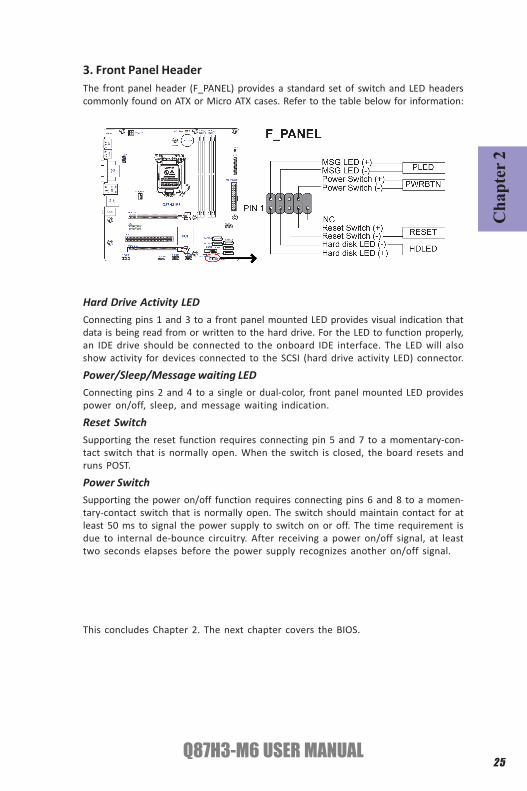
Hard Drive Activity LEDConnecting pins 1 and 3 to a front panel mounted LED provides visual indication thatdata is being read from or written to the hard drive. For the LED to function properly,an IDE drive should be connected to the onboard IDE interface. The LED will alsoshow activity for devices connected to the SCSI (hard drive activity LED) connector.
Power/Sleep/Message waiting LEDConnecting pins 2 and 4 to a single or dual-color, front panel mounted LED providespower on/off, sleep, and message waiting indication.
Reset SwitchSupporting the reset function requires connecting pin 5 and 7 to a momentary-con-tact switch that is normally open. When the switch is closed, the board resets andruns POST.
Power SwitchSupporting the power on/off function requires connecting pins 6 and 8 to a momen-tary-contact switch that is normally open. The switch should maintain contact for atleast 50 ms to signal the power supply to switch on or off. The time requirement isdue to internal de-bounce circuitry. After receiving a power on/off signal, at leasttwo seconds elapses before the power supply recognizes another on/off signal.
3. Front Panel HeaderThe front panel header (F_PANEL) provides a standard set of switch and LED headerscommonly found on ATX or Micro ATX cases. Refer to the table below for information:

Chapter 2
26Q87H3-M6 USER MANUAL
Memo

Q87H3-M6 USER MANUAL27
Cha
pter
3
About the Setup UtilityThe computer uses the latest “American Megatrends Inc.” BIOS with support forWindows Plug and Play. The CMOS chip on the motherboard contains the ROM setupinstructions for configuring the motherboard BIOS.The BIOS (Basic Input and Output System) Setup Utility displays the system’s con-figuration status and provides you with options to set system parameters. The pa-rameters are stored in battery-backed-up CMOS RAM that saves this informationwhen the power is turned off. When the system is turned back on, the system isconfigured with the values you stored in CMOS.
The BIOS Setup Utility enables you to configure:
• Hard drives, diskette drives and peripherals• Video display type and display options• Password protection from unauthorized use• Power Management features
The settings made in the Setup Utility affect how the computer performs. Beforeusing the Setup Utility, ensure that you understand the Setup Utility options.This chapter provides explanations for Setup Utility options.
The Standard ConfigurationA standard configuration has already been set in the Setup Utility. However, we rec-ommend that you read this chapter in case you need to make any changes in thefuture.This Setup Utility should be used:
• when changing the system configuration• when a configuration error is detected and you are prompted to make
changes to the Setup Utility• when trying to resolve IRQ conflicts• when making changes to the Power Management configuration• when changing the password or making other changes to the Security
Setup
Press DEL to enter SETUP
Chapter 3Using BIOS
Entering the Setup UtilityWhen you power on the system, BIOS enters the Power-On Self Test (POST) routines.POST is a series of built-in diagnostics performed by the BIOS. After the POST routinesare completed, the following message appears:

Q87H3-M6 USER MANUAL28
Chapter 3
Press the delete key to access BIOS Setup Utility.
Using BIOSWhen you start the Setup Utility, the main menu appears. The main menu of theSetup Utility displays a list of the options that are available. A highlight indicateswhich option is currently selected. Use the cursor arrow keys to move the highlightto other options. When an option is highlighted, execute the option by pressing<Enter>.
Some options lead to pop-up dialog boxes that prompt you to verify that you wish toexecute that option. Other options lead to dialog boxes that prompt you for informa-tion.
Some options (marked with a triangle ) lead to submenus that enable you to changethe values for the option. Use the cursor arrow keys to scroll through the items in thesubmenu.
The default BIOS setting for this motherboard apply for most conditionswith optimum performance. We do not suggest users change the defaultvalues in the BIOS setup and take no responsibility to any damage causedby changing the BIOS settings.
In this manual, default values are enclosed in parenthesis. Submenu items aredenoted by a triangle .
System BIOS Version Release 09/26/2013 Build Date 09/26/2013EC Firmware Version 05.01 Build Date 06/06/2013Processor Intel(R) Core(TM) i7-4765T CPU @ 2.00GHz Core Frequency 2.00 GHz Count 4Memory Size 4096 MBProduct Name Q87H3-M6System Serial NumberBase Board Serial NumberAsset Tag NumberSystem Date [Thu 09/26/2013]System Time [12:04:42]
Set the Date. Use Tab toswitch between Date elements.
BIOS Setup UtilityMain Advanced Power Authentication Security Boot Options Exit
Version 2.15.1236. Copyright (C) 2002-2013 American Megatrends, Inc.
+/-/Spacebar : Change Opt.Enter : Select
F1: General Help
:Move
F2: Previous Values F3: Optimized Defaults F4: Save and Exit ESC: Discard changes and Exit Setup

Q87H3-M6 USER MANUAL29
Cha
pter
3
BIOS Navigation KeysThe BIOS navigation keys are listed below:
KEY FUNCTION
Scrolls through the items on a menu
+/- Change Opt.
F2 Previous Value
F3 Optimized Defaults
F1 General Help
ESC Exits the current menu
Enter Select
F4 Save & Exit
For the purpose of better product maintenance, the manufacture reservesthe right to change the BIOS items presented in this manual. The BIOS setupscreens shown in this chapter are for reference only and may differ fromthe actual BIOS. Please visit the manufacture’s website for updatedmanual.
Q87H3-M6 USER MANUAL30
Chapter 3
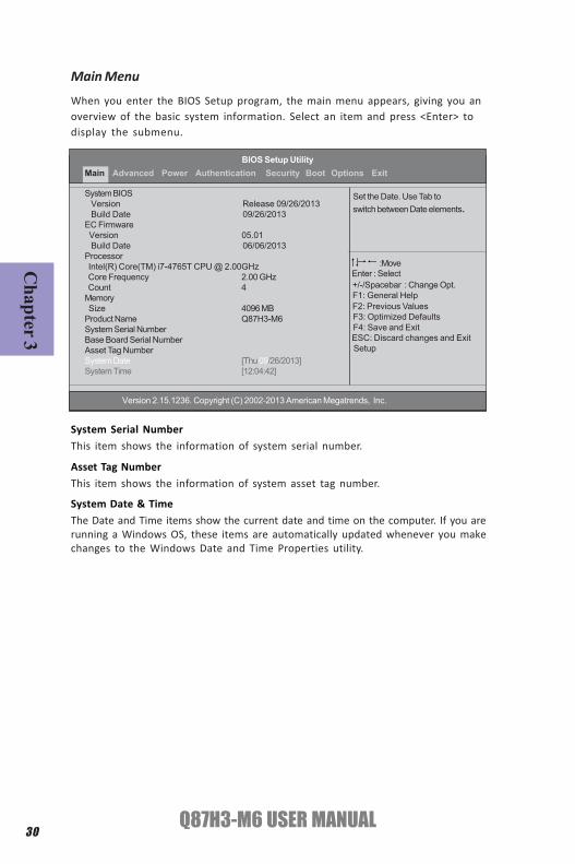
System Date & TimeThe Date and Time items show the current date and time on the computer. If you arerunning a Windows OS, these items are automatically updated whenever you makechanges to the Windows Date and Time Properties utility.
Asset Tag NumberThis item shows the information of system asset tag number.
When you enter the BIOS Setup program, the main menu appears, giving you anoverview of the basic system information. Select an item and press <Enter> todisplay the submenu.
Main Menu
System Serial NumberThis item shows the information of system serial number.
Set the Date. Use Tab toswitch between Date elements.
BIOS Setup UtilityMain Advanced Power Authentication Security Boot Options Exit
Version 2.15.1236. Copyright (C) 2002-2013 American Megatrends, Inc.
System BIOS Version Release 09/26/2013 Build Date 09/26/2013EC Firmware Version 05.01 Build Date 06/06/2013Processor Intel(R) Core(TM) i7-4765T CPU @ 2.00GHz Core Frequency 2.00 GHz Count 4Memory Size 4096 MBProduct Name Q87H3-M6System Serial NumberBase Board Serial NumberAsset Tag NumberSystem Date [Thu 09/26/2013]System Time [12:04:42]
+/-/Spacebar : Change Opt.Enter : Select
F1: General Help
:Move
F2: Previous Values F3: Optimized Defaults F4: Save and Exit ESC: Discard changes and Exit Setup

Q87H3-M6 USER MANUAL31
Cha
pter
3
Aptio Setup Utility - Copyright (C) 2010 American Megatrends, Inc.
BIOS Setup Utility
Miscellaneous Advanced Chipset Configuration
PCI Express Configuration Integrated Peripherals PC Health Status
Miscellaneous
Advanced MenuThis page sets up more advanced information about your system. Handle this pagewith caution. Any changes can affect the operation of your computer.
MiscellaneousScroll to this item and press <Enter> to view the following screen:
AHCI Port1~5
This motherboard supports five SATA channels and each channel allows one SATAdevice to be installed. Use these items to configure each device on the IDE channel.
BIOS Setup Utility
AHCI Port1: Not Present AHCI Port2: Not Present AHCI Port3: Not Present AHCI Port4: Not Present AHCI Port5: Not Present
Spread Spectrum [Enabled] Processor Multiplier 20 Bootup Num-lock [On] USB Beep Message [Disabled]
AHCI Port1
Main Advanced Power Authentication Security Boot Options Exit
Main Advanced Power Authentication Security Boot Options Exit
Processor Multiplier (20)This item shows the information of the processor multiplier.
Spread Spectrum (Enabled)Use this item to enable or disable system Spread Spectrum function, EMI (Electro-Magnetic Interface) will reduce if this item is enabled.
Version 2.15.1236. Copyright (C) 2002-2013 American Megatrends, Inc.
Version 2.15.1236. Copyright (C) 2002-2013 American Megatrends, Inc.
Bootup Num-Lock (On)This item determines if the Num Lock key is active or inactive at system start-uptime.
+/-/Spacebar : Change Opt.Enter : Select
F1: General Help
:Move
F2: Previous Values F3: Optimized Defaults F4: Save and Exit ESC: Discard changes and Exit Setup
+/-/Spacebar : Change Opt.Enter : Select
F1: General Help
:Move
F2: Previous Values F3: Optimized Defaults F4: Save and Exit ESC: Discard changes and Exit Setup

Q87H3-M6 USER MANUAL32
Chapter 3
USB Beep Message (Disabled)This item disables/enables the beep during USB device enumeration.
Press <Esc> to return to the Advanced Menu page.

Q87H3-M6 USER MANUAL33
Cha
pter
3
Intel EIST [Enabled] Intel Turbo Boost [Enabled] Intel AES-NI [Disabled] Intel XD Bit [Enabled] Intel VT [Enabled] Intel AMT [Enabled] Intel VT-d [Disabled] Intel TXT [Disabled] Primary Video [Auto] Video Memory Size [64MB] DVMT Mode [DVMT] DVMT Memory Size [256MB]
Advanced Chipset ConfigurationThis item allows you to enable or disable the Intel AES-NI technology.
BIOS Setup Utility
Intel EIST
Intel VT (Enabled)This item allows you to enable or disable the Intel VT function.
Intel EIST (Enabled)This item allows users to enable or disable the EIST(Enhanced Intel SpeedStep tech-nology).
Intel AES-NI (Disabled)This item allows users to enable or disable the Intel AES-NI.
Intel VT-d (Disabled)This item allows you to enable or disable the Intel VT-d function.Intel TXT (Disabled)This item allows you to enable or disable the Intel TXT function.
Intel XD Bit (Enabled)This item allows users to enable or disable the Intel XD Bit.
Intel Turbo Boost (Enabled)This item enables or disables Intel Turbo Boost.
Intel AMT (Enabled)This item allows you to enable or disable the Intel AMT function.
Primary Video (Auto)This item indicates the primary video device setting.
Main Advanced Power Authentication Security Boot Options Exit
Version 2.15.1236. Copyright (C) 2002-2013 American Megatrends, Inc.
Video Memory Size (64MB) *This item applies to chipset/motherboards capable of the HyperMemory Support.
+/-/Spacebar : Change Opt.Enter : Select
F1: General Help
:Move
F2: Previous Values F3: Optimized Defaults F4: Save and Exit ESC: Discard changes and Exit Setup

Q87H3-M6 USER MANUAL34
Chapter 3
DVMT Memory Size (256MB) *
When set to DVMT Mode, the graphics chip will dynamically allocate system memoryas graphics memory, according to system and graphics requirements.
DVMT Mode (DVMT) *
DVMT is Dynamic Video Memory Technology. This item shows the Mode of DVMT.
* These items will be hidden when Onboard Graphics Controller is setto be disabled or there is no Onboard Graphics Controller.
Press <Esc> to return to the Advanced Menu page.

Q87H3-M6 USER MANUAL35
Cha
pter
3
BIOS Setup Utility
NB PCI Express Configuration
PCI Express 16XPCI Express 16X Speed [Auto]
PCI Express Configuration
PCIE1PCI Express Speed [Auto]
PCI Express X16_SPCI Express Speed [Auto]
Configure PCI Express 16XSpeed B0:D1:F0 Gen1-Gen3
PCI Express ConfigurationScroll to this item and press <Enter> to view the following screen:
Main Advanced Power Authentication Security Boot Options Exit
Version 2.15.1236. Copyright (C) 2002-2013 American Megatrends, Inc.
PCI Express 16X/PCIE1/PCI Express X16_S speed (Auto)This item allows users to configure the PCI Express 16X/PCIE1/PCI Express X16_Sspeed.
Press <Esc> to return to the Advanced Menu page.
+/-/Spacebar : Change Opt.Enter : Select
F1: General Help
:Move
F2: Previous Values F3: Optimized Defaults F4: Save and Exit ESC: Discard changes and Exit Setup

Q87H3-M6 USER MANUAL36
Chapter 3
Integrated PeripheralsThis page sets up some parameters for peripheral devices connected to the system.
Onboard SATA Controller (Enabled)This item allows you to enable or disable the onboard SATA controller.Onboard SATA Mode (AHCI)Use this item to select the mode of the Serial ATA.
BIOS Setup Utility
Onboard SATA Controller [Enabled]Onboard SATA Mode [AHCI]Onboard USB Controller [Enabled]Legacy USB Support [Enabled]USB Storage Emulation [Auto]Onboard Graphics Controller [Enabled]Onboard Audio Controller [Enabled]Onboard LAN Controller [Enabled]Onboard LAN Option ROM [Disabled]Serial Port1 Address [3F8/IRQ4]Serial Port2 Address [2F8/IRQ3]Parallel Port Address [378]Parallel Port Mode [Normal]Parallel Port IRQ [IRQ7]
Onboard SATA Controller.
Onboard USB Controller (Enabled)Use this item to enable or disable the onboard USB controller. We recommend userskeep the default value.
Legacy USB Support (Enabled)Use this item to enable or disable support for legacy USB devices. Disabling it mightcause the USB devices not to work properly.
USB Storage Emulation (Auto)If Auto, USB device equal or less than 2GB will be emulated as Floppy and remainingas hard drive. Forced FDD option can be used to force a HDD formatted drive to bootas FDD (Ex. ZIP drive).
Main Advanced Power Authentication Security Boot Options Exit
Serial Port1 Address (3F8/IRQ4)Use this item to enable or disable the onboard COM1 serial port, and to assign a portaddress.
Onboard LAN Option ROM (Disabled)This item enables or disables the onboard LAN option ROM function.
Onboard LAN Controller (Enabled)This option allows you to control the onboard LAN device.
Onboard Audio Controller (Enabled)This item enables or disables the onboard audio controller.
Onboard Graphics Controller (Enabled)This item indicates the status of the onboard graphics controller.
Version 2.15.1236. Copyright (C) 2002-2013 American Megatrends, Inc.
+/-/Spacebar : Change Opt.Enter : Select
F1: General Help
:Move
F2: Previous Values F3: Optimized Defaults F4: Save and Exit ESC: Discard changes and Exit Setup

Q87H3-M6 USER MANUAL37
Cha
pter
3
Parallel Port Mode (Normal)Use this item to select the parallel port mode. You can select Normal (StandardParallel Port), ECP (Extended Capabilities Port), EPP (Enhanced Parallel Port), or Bpp(Bi-Directional Parallel Port).
Parallel Port IRQ (IRQ7)Use this item to assign IRQ to the parallel port.
Serial Port2 Address (2F8/IRQ3)Use this item to enable or disable the onboard parallel port, and to assign a portaddress.
Parallel Port Address (378)Use this item to enable or disable the onboard COM2 serial port, and to assign a portaddress.
Press <Esc> to return to the Advanced Menu page.

Q87H3-M6 USER MANUAL38
Chapter 3
PC Health StatusOn motherboards support hardware monitoring, this item lets you monitor theparameters for critical voltages, temperatures and fan speeds.
CPU Temperature (DTS)This item shows the CPU DTS data for thermal reference.System Ambient TemperatureThis item shows the system Ambient temperature.
System Component CharacteristicsThese items display the monitoring of the overall inboard hardware health events,such as System & CPU temperature, CPU voltage, CPU & system fan speed...etc.
• PCH Temperature • Vcore Temperature • CPU Fan Speed • System Fan Speed • Vcore • Vmemory • + 12.0 V • + 5.00V • VCC3
BIOS Setup Utility
CPU Temperature (DTS) : 46 System Ambient Temperature : 30°C/86°F PCH Temperature : 41 Vcore Temperature : 50 CPU Fan Speed : 1035 RPM System Fan Speed : N/A VCore : 1.727 V Vmemory : 1.496 V +12.0V : 12.051 V +5.00V : 5.134 VVCC3 : 3.412 V Smart Fan [Enabled]
System Shutdown Temperature
Main Advanced Power Authentication Security Boot Options Exit
Version 2.15.1236. Copyright (C) 2002-2013 American Megatrends, Inc.
+/-/Spacebar : Change Opt.Enter : Select
F1: General Help
:Move
F2: Previous Values F3: Optimized Defaults F4: Save and Exit ESC: Discard changes and Exit Setup
Smart Fan (Enabled)This item shows you to disable/enable the control of the CPU fan speed by changingthe fan voltage.

Q87H3-M6 USER MANUAL39
Cha
pter
3Power on by RTC Alarm (Disabled)This system can be turned off with a software command. If you enable this item, thesystem can automatically resume at a fixed time based on the system RTC (realtimeclock). Use the items below this one to set the date and time of the wake-up alarm.You must use an ATX power supply in order to use this feature.
Power on by PCIE Devices (Enabled)This system can be turned off with a software command. If you enable this item, thesystem can automatically resume if there is an incoming call on the PCIE LAN card.You must use an ATX power supply in order to use this feature. Use this item to dowake-up action if inserting the PCIE card.
Power MenuThis page sets up some parameters for system power management operation.
ACPI Suspend Mode [S3(STR)]Use this item to define how your system suspends. In the default, S3(STR), the sus-pend mode is suspend to RAM, i.e., the system shuts down with the exception of arefresh current to the system memory.
Deep Power off Mode (Enabled)This item allows users to enable or disable the Deep Power off Mode.
BIOS Setup Utility
ACPI Aware O/S [Yes]ACPI Suspend Mode [S3(STR)]Deep Power off Mode [Enabled]Power on by RTC Alarm [Disabled]Power on by PCIE Devices [Enabled]Power on by PCI Devices [Enabled]Power on by Modem Ring [Enabled]Power on by Onboard LAN [Enabled]Wake up by PS/2 KB/Mouse [S3]Wake up by USB KB/Mouse [S3]Restore On AC Power Loss [Off]
Select the highest ACPI sleepstate the system will enterwhen the SUSPEND button ispressed.
ACPI Adware O/S (Yes)This item supports ACPI (Advanced Configuration and Power ManagementInterface). Use this item to enable ACPI feature.
Main Advanced Power Authentication Security Boot Options Exit
Power on by PCI Devices (Enabled)This system can be turned off with a software command. If you enable this item, thesystem can automatically resume if there is an incoming call through the PCI deviceconnected. You must use an ATX power supply in order to use this feature. Use thisitem to do wake-up action if inserting the PCI device.
Version 2.15.1236. Copyright (C) 2002-2013 American Megatrends, Inc.
+/-/Spacebar : Change Opt.Enter : Select
F1: General Help
:Move
F2: Previous Values F3: Optimized Defaults F4: Save and Exit ESC: Discard changes and Exit Setup

Q87H3-M6 USER MANUAL40
Chapter 3
Wake up by PS/2 KB/Mouse (S3)This item enables or disables you to allow keyboard or mouse activity to awaken thesystem from power saving mode.Wake up by USB KB/Mouse (S3)This item enables or disables you to allow keyboard or mouse activity to awaken thesystem from power saving mode.
Power on by Modem Ring (Enabled)This system can be turned off with a software command. If you enable this item, thesystem can automatically resume if there is an incoming call on the Modem. Youmust use an ATX power supply in order to use this feature.
This item defines how the system will act after AC power loss during system operation.When you set Off, it will keep the system in Off state until the power button is pressed.
Restore On AC Power Loss (Off)
Power on by Onboard LAN (Enabled)This system can be turned off with a software command. If you enable this item,the system can automatically resume if there is an incoming call on the onboardLAN card. You must use an ATX power supply in order to use this feature.

Q87H3-M6 USER MANUAL41
Cha
pter
3
This page sets secure boot mode.
Authentication Menu
System Boot State (User)This item shows the system boot state.Secure Boot Mode State (Enabled)This item enables or disables the secure boot mode state.Secure Boot (Enabled)This item is used to control the secure boot flow, it is possible only if system runsin User Mode.
Secure Boot flow control.Secure Boot can be enabled onlywhen 1.Platform Key(PK) is en-rolled and Platform is operating inuser mode and 2.CSM function isdisabled in Setup
System Boot State UserSecure Boot Mode State DisabledSecure Boot [Disabled]
BIOS Setup UtilityMain Advanced Power Authentication Security Boot Options Exit
Version 2.15.1236. Copyright (C) 2002-2013 American Megatrends, Inc.
+/-/Spacebar : Change Opt.Enter : Select
F1: General Help
:Move
F2: Previous Values F3: Optimized Defaults F4: Save and Exit ESC: Discard changes and Exit Setup

Q87H3-M6 USER MANUAL42
Chapter 3
TPM Active Status (Activated)This item displays the TPM status to be active or not.TPM Owner Status (UnOwned)This item displays the TPM to be owned or not.Removable Device Boot (Enabled)This item enables or disables support the boot from USB mass storage devices.
This page enables you to set setup administrator and password.
Security Menu
Supervisor Password (Not Installed)This item indicates whether a supervisor password has been set. If the passwordhas been installed, Installed displays. If not, Not Installed displays.User Password (Not Installed)This item indicates whether a user password has been set. If the password has beeninstalled, Installed displays. If not, Not Installed displays.Change Supervisor Password (Press Enter)You can select this option and press <Enter> to access the sub menu. You can use thesub menu to change the supervisor password.
BIOS Setup Utility
Supervisor Password : Not InstalledUser Password : Not InstalledChange Supervisor Password [Press Enter] TPM Support [Enabled] TPM State [Disabled]TPM Operation [None]
Current TPM Status TPM Enabled Status [Disabled] TPM Active Status [Activated] TPM Owner Status [Owned]
Removable Device Boot [Enabled ]
Chassis Opened Warning [Disabled]Chassis Opened YesME Enable [Enabled]
Valid Keys:(1)a-z (A-Z) non case sensitive(2)0, 1-9(3)11 special keys:’-=[]\;’,./(4)key pad: 0-9 support and/*-+.(5 special keys)(5)Only support scan code
TPM Support (Enabled)This item is set to support TPM (Trusted Platform Module) funtion.TPM State (Disabled)This item displays the TPM status to be enabled/disabled.TPM Operation (None)This item shows the information of the TPM operation.TPM Enabled Status (Disabled)This item displays the TPM status to be enable/disable.
Main Advanced Power Authentication Security Boot Options Exit
Version 2.15.1236. Copyright (C) 2002-2013 American Megatrends, Inc.
+/-/Spacebar : Change Opt.Enter : Select
F1: General Help
:Move
F2: Previous Values F3: Optimized Defaults F4: Save and Exit ESC: Discard changes and Exit Setup

Q87H3-M6 USER MANUAL43
Cha
pter
3
Chassis Opened Warning (Enabled)This item enables or disables the warning if the case is opened up, and the itembelow indicates the current status of the case.Chassis Opened (Yes)This item indicates whether the case has been opened.
ME Enable (Enabled)Use this item to enable or disable the ME Firmware.

Q87H3-M6 USER MANUAL44
Chapter 3
Boot Options Menu
Boot ConfigurationThis item.
BIOS Setup Utility
This option controls if CSM will be launched
Boot Priority Order 1st Boot Device [Hard Disk] 2nd Boot Device [CD&DVD] 3rd Boot Device [Removable Device] 4th Boot Device [LAN]
Hard Disk Drive Priority [Press Enter] Optical Disk Drive priority [Press Enter] Removable Device Priority [Press Enter] Network Device Priority [Press Enter]
Boot Menu [Disabled] Quiet Boot [Enabled] Halt On [All, but keyboard]
This page enables you to set the keyboard Numlock state.
Main Advanced Power Authentication Security Boot Options Exit
Launch CSM [Always]Launch PXE OPROM [Legacy]Launch Storage OPROM [Legacy]Launch Video OPROM [Legacy]
Boot Priority OrderThis item enables you to set boot priority order.
1st/2nd/3rd/4th Boot DeviceThese items show the boot priorities.
Hard Disk Drive/ Optical Disk Drive/ Removable Device/ Network Device PrioritiesThese items enable you to specify the sequence of loading the operatingsystem.Press <Enter> to see the submenu.
Version 2.15.1236. Copyright (C) 2002-2013 American Megatrends, Inc.
Launch CSM (Always)This option controls if CSM will be launched.Launch PXE OPROM (Legacy)These items enables or disables launch PXE OPROM.
Launch Storage OPROM (Legacy)These items enables or disables launch Storage OPROM.Launch Video OPROM (Legacy)These items enables or disables launch Video OPROM.
+/-/Spacebar : Change Opt.Enter : Select
F1: General Help
:Move
F2: Previous Values F3: Optimized Defaults F4: Save and Exit ESC: Discard changes and Exit Setup

Q87H3-M6 USER MANUAL45
Cha
pter
3
This page enables you to exit system setup after saving or without saving thechanges.
Exit Menu
BIOS Setup Utility
Exit system setup after savingthe changes.
Save & Exit SetupDiscard Changes and Exit SetupSave ChangesDiscard ChangeLoad Default SettingsSave as User Default SettingsLoad User Default Settings
If you have made settings that you do not want to save, use the “Discard Changesand Exit” item and select [OK] to discard any changes you have made.
Save & Exit SetupThis item enables you to save the changes that you have made and exit.
Load User Default SettingsUse this item to restore user defaults.
Save as User Default SettingsUse this item to save the changes that you have made as user defaults.
Load Default SettingsThis item enables you to restore the system defaults.
Discard ChangesUse this item to discard any changes that you have made.
Save ChangesUse this item to save the changes that you have made.
Discard Changes and Exit SetupUse this item to discard any changes that you have made and exit.
Main Advanced Power Authentication Security Boot Options Exit
Version 2.15.1236. Copyright (C) 2002-2013 American Megatrends, Inc.
+/-/Spacebar : Change Opt.Enter : Select
F1: General Help
:Move
F2: Previous Values F3: Optimized Defaults F4: Save and Exit ESC: Discard changes and Exit Setup

Q87H3-M6 USER MANUAL46
Chapter 3
Updating the BIOSYou can download and install updated BIOS for this motherboard from themanufacturer’s Web site. New BIOS provides support for new peripherals, improve-ments in performance, or fixes for known bugs. Install new BIOS as follows:
1 If your motherboard has a BIOS protection jumper, change the setting toallow BIOS flashing.
2 If your motherboard has an item called Firmware Write Protect in Ad-vanced BIOS features, disable it. (Firmware Write Protect prevents BIOSfrom being overwritten.)
3 Prepare a bootable device or create a bootable system disk. (Refer toWindows online help for information on creating a bootable system disk.)
4 Download the Flash Utility and new BIOS file from the manufacturer’sWeb site. Copy these files to the bootable device.
5 Turn off your computer and insert the bootable device in your computer.(You might need to run the Setup Utility and change the the boot priorityitems on the Advanced BIOS Features Setup page, to force your computerto boot from the bootable device first.)
6 At the C:\ or A:\ prompt, type the Flash Utility program name and the filename of the new BIOS and then press <Enter>. Example: AFUDOS.EXE040706.ROM
7 When the installation is complete, remove the bootable device from thecomputer and restart your computer. If your motherboard has a FlashBIOS jumper, reset the jumper to protect the newly installed BIOS frombeing overwritten. The computer will restart automatically.

47Q87H3-M6 USER MANUAL
Cha
pter
4
Chapter 4Intel® Matrix Storage Manager RAID ConfigurationThe Intel® Matrix Storage Manager allows you to configure RAID 0, and 1 sets on theexternal Serial ATA hard disk drives.
1. Install the external Serial ATA hard disk drive (HDD) on your system.
2. Set the SATA Mode item in the BIOS from “IDE Mode” to “RAID Mode”
See section “SATA Configuration” for details.
Before creating a RAID set
1. One SATA HDD.2. A write-enabled floppy disk.3. Microsoft® Windows® OS installation disk (Windows XP/7/8).4. Motherboard support CD with Intel® Matrix Storage Manager driver.
Complete the following steps before you create a RAID set:
Prepare the following items:
Version 2.15.1236. Copyright (C) 2002-2013 American Megatrends, Inc.
3. Enter the Intel® Matrix Storage Manager option to set up your RAIDconfiguration.
4. Create an Intel® Matrix Storage Manager driver disk for Windows® OS in-stallation. See section “Creating a RAID driver disk” for details.
5. Install the Intel® Matrix Storage Manager driver after the Windows® OShad been installed.
BIOS Setup Utility
Onboard SATA Controller [Enabled]Onboard SATA Mode [RAID]Onboard USB Controller [Enabled]Legacy USB Support [Enabled]USB Storage Emulation [Auto]Onboard Graphics Controller [Enabled]Onboard Audio Controller [Enabled]Onboard LAN Controller [Enabled]Onboard LAN Option ROM [Disabled]Serial Port1 Address [3F8/IRQ4]Serial Port2 Address [2F8/IRQ3]Parallel Port Address [378]Parallel Port Mode [Normal]Parallel Port IRQ [IRQ7]
Onboard SATA Controller.
Main Advanced Power Authentication Security Boot Options Exit
+/-/Spacebar : Change Opt.Enter : Select
F1: General Help
:Move
F2: Previous Values F3: Optimized Defaults F4: Save and Exit ESC: Discard changes and Exit Setup
Version 2.15.1236. Copyright (C) 2002-2013 American Megatrends, Inc.
48Q87H3-M6 USER MANUAL
Chapter 4
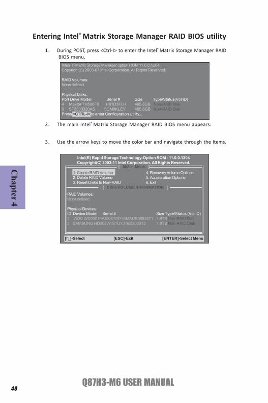
2. The main Intel® Matrix Storage Manager RAID BIOS menu appears.
Entering Intel® Matrix Storage Manager RAID BIOS utility
1. During POST, press <Ctrl-I> to enter the Intel® Matrix Storage Manager RAIDBIOS menu.
3. Use the arrow keys to move the color bar and navigate through the items.
Intel(R) Matrix Storage Manager option ROM 11.0.0.1204Copyright(C) 2003-07 Intel Corporation. All Rights Reserved.
RAID Volumes:None defined.
Physical Disks:Port Drive Model Serial # Size Type/Status(Vol ID)4 Maxtor 7H500F0 H81D3FLH 465.8GB Non-RAID Disk5 ST3500320AS 5QM0KLEY 465.8GB Non-RAID DiskPress <CTRL-I> to enter Configuration Utility...
[ Main Menu ]1. Create RAID Volume 4. Recovery Volume Options2. Delete RAID Volume 5. Acceleration Options3. Reset Disks to Non-RAID 6. Exit
[ DISK/VOLUME INFORMATION ]
RAID Volumes:None defined.
Physical Devices:ID Device Model Serial # Size Type/Status (Vol ID)2 WDC WD2001FASS-0 WD-WMAUR0083571 1.8TB Non-RAID Disk3 SAMSUNG HD203WI S1UYJ1BZ203313 1.8TB Non-RAID Disk
[ ]-Select [ESC]-Exit [ENTER]-Select Menu
Intel(R) Rapid Storage Technology-Option ROM - 11.0.0.1204Copyright(C) 2003-11 Intel Corporation. All Rights Reserved.

49Q87H3-M6 USER MANUAL
Cha
pter
4
2. When the RAID Level item is highlighted, use the up/down arrow key toselect the RAID set that you want to create.
Creating a RAID set
1. In the main Intel® Matrix Storage Manager RAID BIOS menu, highlightCreate RAID Volume using the up/down arrow key then press <Enter>.
3. Key in the RAID volume capacity. Use the up/down arrow to choose theCapacity. The default value indicates the maximum capacity using theselected disks. Entering a lower capacity allows you to create a secondvolume on these disks.
When more than two HDDs are installed in your computer, the Disks itemwill be selectable. Then users can select the HDD that you want to belongto the RAID set. Please be noticed that selecting a wrong disk will result inlosing the original data of the HDD.
[ Main Menu ]1. Create RAID Volume 4. Recovery Volume Options2. Delete RAID Volume 5. Acceleration Options3. Reset Disks to Non-RAID 6. Exit
[ CREATE VOLUME MENU ]
Name: Volume0RAID Level: RAID0(Stripe) Disks: Select Disks Strip Size: 128KB Capacity: 931.5 GB
Create Volume
[ CREATE VOLUME MENU ]
Name: Volume0RAID Level: RAID1(Mirror) Disks: Select Disks Strip Size: N/A Capacity: 465.8 GB
Create Volume
[ CREATE VOLUME MENU ]
Name: Volume0RAID Level: RAID0(Stripe) Disks: Select Disks Strip Size: 128KB Capacity: 931.5 GB
Create Volume
[ CREATE VOLUME MENU ]
Name: Volume0RAID Level: RAID0(Stripe) Disks: Select Disks Strip Size: 128KB Capacity: 931.5 GB
Create Volume

50Q87H3-M6 USER MANUAL
Chapter 4
Pressing <Y> deletes all the data in the HDDs.
5. The following screen appears, displaying the relevant information aboutthe RAID set you created.
Users please be noted that RAID 0 (Stripe) is set to accelerate the dataaccess, and RAID 1 (Mirror) is set to provide the data backup. If you wantto set RAID 0, you need to set the 2nd Boot Device item in the BIOS to IntelVolume0. See section “Advanced Setup” for details.
4. When done, press <Enter> to confirm the creation of the RAID set. Adialogue box appears to confirm the action. Press <Y> to confirm;otherwise, press <N>.
[ CREATE VOLUME MENU ] Name: Volume0RAID Level: RAID0(Stripe) Disks: Select Disks Strip Size: 128KB Capacity: 931.5 GB
[ ]Change [TAB]-Next [ESC]-Previous Menu [ENTER]-Select
Intel(R) Matrix Storage Manager option ROM 11.0.0.1204Copyright(C) 2003-07 Intel Corporation. All Rights Reserved.
Press ENTER to create the specified volume.
WARNING: ALL DATA ON SELECTED DISKS WILL BE LOST.Are you sure you want to create this volume? (Y/N):
[ DISK/VOLUME INFORMATION ]RAID Volumes:ID Name Level Strip Size Status Bootable0 Volume0 RAID0(Stripe) 128KB 931.5GB Normal Yes
Physical Disks:Port Drive Model Serial # Size Type/Status (Vol ID)4 Maxtor 7H500F0 H81D3FLH 465.8GB Member Disk(0)5 ST3500320AS 5QM0KLEY 465.8GB Member Disk(0)

51Q87H3-M6 USER MANUAL
Cha
pter
4
Deleting a RAID set
1. In the main Intel® Matrix Storage Manager RAID BIOS menu, highlight DeleteRAID Volume using the up/down arrow key then press <Enter>.
2. Use the space bar to select the RAID set you want to delete.
Press the <Del> key to delete the set.
3. A dialogue box appears to confirm the action. Press <Y> to confirm;otherwise, press <N>.
Pressing <Y> deletes all the data in the HDDs.
[ Main Menu ]1. Create RAID Volume 4. Recovery Volume Options2. Delete RAID Volume 5. Acceleration Options3. Reset Disks to Non-RAID 6. Exit
[ CREATE VOLUME MENU ]Name Level Drives Capacity Status BootableVolume0 RAID0(Stripe) 2 931.5GB Normal Yes
[ ]Select [ESC]-Previous Menu [DEL]-Delete Volume
Intel(R) Matrix Storage Manager option ROM 11.0.0.1204Copyright(C) 2003-07 Intel Corporation. All Rights Reserved.
Deleting a volume will reset the disks to non-RAID.
WARNING: ALL DISK DATA WILL BE DELETED.
ALL DATA IN THE VOLUME WILL BE LOST!
Are you sure you want to delete “Volume0”? (Y/N):
[ DELETE VOLUME VERIFICATION ]
Boot ConfigurationThis item.
BIOS Setup UtilityMain Advanced Power Authentication Security Boot Options Exit
+/-/Spacebar : Change Opt.Enter : Select
F1: General Help F2: Previous Values F3: Optimized Defaults F4: Save and Exit ESC: Discard changes and Exit Setup
:Move
Hard Disk Drive Priorities
1st Boot Intel volume0
Version 2.15.1236. Copyright (C) 2002-2013 American Megatrends, Inc.
Sets the system boot order

52Q87H3-M6 USER MANUAL
Chapter 4
Resetting disks to Non-RAID An HDD that has been previously configured as part of another RAID setin another platform is called a broken RAID HDD. When you install a brokenRAID HDD, you cannot select this disk when configuring a RAID set throughthe Intel® Matrix Storage Manager option. If you still want to use thisbroken RAID HDD as part of the RAID set configured through the Intel®
Matrix Storage Manager, you may do so by resetting the disk to Non-RAID.You will, however, lose all data and previous RAID configurations.
To reset disks to Non-RAID:1. In the main Intel® Matrix Storage Manager RAID BIOS menu, highlight Reset
Disks to Non-RAID using the up/down arrow key then press <Enter>.
2. Use the space bar to select the HDD to reset to Non-RAID.
3. A dialogue box appears to confirm the action. Press <Y> to confirm;otherwise, press <N>.
Pressing <Y> deletes all the data in the HDDs.
When you have finished, highlight Exit using the up/down arrow key then press<Enter> to exit the Intel® Matrix Storage Manager RAID BIOS utility.
A dialogue box appears to confirm the action. Press <Y> to confirm; otherwise, press<N> to return to the Intel® Matrix Storage Manager RAID BIOS menu.
Exiting Setup
[ Main Menu ]1. Create RAID Volume 4. Recovery Volume Options2. Delete RAID Volume 5. Acceleration Options3. Reset Disks to Non-RAID 6. Exit

53Q87H3-M6 USER MANUAL
Cha
pter
5
Chapter 5Trouble ShootingStart up problems during assemblyAfter assembling the PC for the first time you may experience some start upproblems. Before calling for technical support or returning for warranty, thischapter may help to address some of the common questions using some basictroubleshooting tips.
a) System does not power up and the fans are not running.1. Disassemble the PC to remove the VGA adaptor card, DDR memory, LAN, USB andother peripherals including keyboard and mouse. Leave only the motherboard,CPU with CPU cooler and power supply connected. Make sure the power cord isplugged into the wall socket & the switch on the Power Supply Unit (PSU) is turned“ on “ as well. Turn on again to see if the CPU and power supply fans are running.
2. Make sure to remove any unused screws or other metal objects such asscrewdrivers from the inside PC case. This is to prevent damage from short circuit.
3. Check the CPU FAN connector is connected to the motherboard.
4. For Intel platforms check the pins on the CPU socket for damage or bent. A bentpin may cause failure to boot and sometimes permanent damage from short circuit.
5. Check the 12V power connector is connected to the motherboard.
6. Check that the 12V power & ATX connectors are fully inserted into themotherboard connectors. Make sure the latches of the cable and connector arelocked into place.
b) Power is on, fans are running but there is no display1. Make sure the monitor is turned on and the monitor cable is properly connectedto the PC.
2. Check the VGA adapter card (if applicable) is inserted properly.
3. Listen for beep sounds. If you are using internal PC speaker make sure it isconnected. a. continuous 3 short beeps: memory not detected b. 1 long beep and 8 short beeps: VGA not detected
c) The PC suddenly shuts down while booting up.1. The CPU may experience overheating so it will shutdown to protect itself. Applythe thermal grease onto the CPU heatsink & ensure the CPU fan is well-connectedwith the CPU heatsink. Check if the CPU fan is working properly while the systemis running.

54Q87H3-M6 USER MANUAL
Chapter 5
Your computer, like any electrical appliance, requires proper care andmaintenance. Here are some basic PC care tips to help prolong the life of themotherboard and keep it running as best as it can.
1. Keep your computer in a well ventilated area. Leave some space between the PC and the wall for sufficient airflow.
2. Keep your computer in a cool dry place. Avoid dusty areas, direct sunlight and
Start up problems after prolong useAfter a prolong period of use your PC may experience start up problems again. Thismay be caused by breakdown of devices connected to the motherboard such asHDD, CPU fan, etc. The following tips may help to revive the PC or identify the causeof failure.1. Clear the CMOS values using the CLR_CMOS jumper. Refer to CLR_CMOS jumperin Chapter 2 for Checking Jumper Settings in this user manual. When completed,follow up with a Load Optimised Default in the BIOS setup.
2. Check the CPU cooler fan for dust. Long term accumulation of dust will reduce itseffectiveness to cool the processor. Clean the cooler or replace a new one ifnecessary.
3. Check that the 12V power & ATX connectors are fully inserted into themotherboard connectors. Make sure the latches of the cable and connector arelocked into place.
4. Remove the hard drive, optical drive or DDR memory to determine which ofthese components may be at fault.
areas of high moisture content.
3. Routinely clean the CPU cooler fan to remove dust and hair.
4. In places of hot and humid weather you should turn on your computer once every other week to circulate the air and prevent damage from humidity.
5. Add more memory to your computer if possible. This not only speeds up the system but also reduces the loading of your hard drive to prolong its life span.
6. If possible, ensure the power cord has an earth ground pin directly from the wall outlet. This will reduce voltage fluctuation that may damage sensitive devices.
Maintenance and care tips
2. From the BIOS setting, try to disable the Smartfan function to let the fan run atdefault speed. Doing a Load Optimised Default will also disable the Smartfan.
5. Check whether there is any bulked up electrolytic capacitor or abnormalcomponent.

uB rewoP
desserp si no .trats ot sliaf CP tub
seY
ylppuS rewoP fi kcehC
tinUgnikro
w si )USP(
No Nodnuos peeB ynA
No kcehc dna SO
MC RLC
rewop V21 UPC fi
detcennoc si
CP eht tratseR
?draob ro USP htiw
melborP
AMR tcatnoc >-
melborp draob fI
deulp si droc re
wop CAgg
?no denrut si hctiws USP dna
seY
melborp draoB
AMR tcatnoc >-
No
:speeb trohs 3 fI -
ylreporp ton yrome
m M
MID
eruliaf yrome
m ro detresni
:speeb trohs 8 dna peeb gnol 1 fI -
detceted ton AGV
seY seY
neercs TSOP ta tlaH
seY
OMC RL
dna SC
tser .tra A
MR tcatnoc ,liaf fI
seY
No
eussi ecived larehpireP
.melborp DDH
-
,rorre putes SOMC
-
d .SO
MCRLC ot een
ts ot liaf metsyS
elbatsnu ro tra
aes SOIB yfido
m re .gn
M SO
C RLC tratser dna
hctiws USP no nruT
tekcos llaw ot tcennoc ro
.tratser dna
No
h rotino
m fi kcehCsa
sidyalp
rotinom fi kcehC
yalpsid sah
Basic
Tro
uble
shoo
ting
Flow
char
t
55

56Q87H3-M6 USER MANUAL
Chapter 5
Memo