Embed Size (px)
Citation preview
A0017767
February 2020 Rev. 49
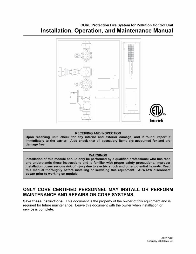
CORE Protection Fire System for Pollution Control Unit Installation, Operation, and Maintenance Manual
ONLY CORE CERTIFIED PERSONNEL MAY INSTALL OR PERFORM MAINTENANCE AND REPAIRS ON CORE SYSTEMS. Save these instructions. This document is the property of the owner of this equipment and is required for future maintenance. Leave this document with the owner when installation or service is complete.
RECEIVING AND INSPECTION Upon receiving unit, check for any interior and exterior damage, and if found, report it immediately to the carrier. Also check that all accessory items are accounted for and are damage free.
WARNING!!
Installation of this module should only be performed by a qualified professional who has read and understands these instructions and is familiar with proper safety precautions. Improper installation poses serious risk of injury due to electric shock and other potential hazards. Read this manual thoroughly before installing or servicing this equipment. ALWAYS disconnect power prior to working on module.
2
Table of Contents WARRANTY .................................................................................................................................................. 3 INSTALLATION ............................................................................................................................................. 3
Mechanical ................................................................................................................................................ 4 Plumbing Connections ........................................................................................................................... 4 Piping Loss Calculation for Wall Mount CORE Protection Fire System ................................................ 5 Discharge Coefficient for PCU ............................................................................................................... 6
Electrical .................................................................................................................................................... 8 Wiring Distance Limitations ................................................................................................................... 9 Fire Alarm Contacts ............................................................................................................................... 9 Fire Group ............................................................................................................................................ 10
OPERATION ............................................................................................................................................... 11 CORE Protection Fire System ................................................................................................................. 11 CORE Protection Test Mode Overview ................................................................................................... 11 CORE Protection Reset Overview .......................................................................................................... 11 CORE Protection Fire System Option Start Up ....................................................................................... 12
Special Tools Required ........................................................................................................................ 12 Jobsite Qualifications – Pre-installation CORE Protection Fire System .............................................. 12 Start Up Procedure – CORE Protection Fire System .......................................................................... 12 Start Up Procedure – Battery Back Up ................................................................................................ 13 Start Up Procedure – Final .................................................................................................................. 13 Reset Procedure – CORE Protection Fire System .............................................................................. 13 CORE Protection System Start-up Checklist ....................................................................................... 13 CORE Protection System Reset Checklist .......................................................................................... 13
Component Description ........................................................................................................................... 14 Water Manifold ..................................................................................................................................... 14 CORE Protection Fire System Printed circuit board ............................................................................ 16 Connector Descriptions ....................................................................................................................... 17 DIP Switch Settings ............................................................................................................................. 20 Typical CORE DIP Switch Arrangement .............................................................................................. 21 Appliance Shutdown in Fault Conditions ............................................................................................. 22 Local Alarm Muting .............................................................................................................................. 22
CORE Protection Firestat ........................................................................................................................ 23 Non-Solid Fuel Appliances (Rated 450°F) ........................................................................................... 23 Non-Solid Fuel Appliances (Rated 600°F) ........................................................................................... 23 Solid Fuel Appliances (Rated 700°F) .................................................................................................. 23 Surfactant Tank .................................................................................................................................... 26 Battery Backup ..................................................................................................................................... 27 Power Supply Adjustment .................................................................................................................... 27 CORE Protection Waterline Supervision ............................................................................................. 28
TROUBLESHOOTING ................................................................................................................................ 29 CORE Protection Fire System Troubleshooting Chart ............................................................................ 29 CORE Common Wiring Troubleshooting ................................................................................................ 30
MAINTENANCE .......................................................................................................................................... 31 General Maintenance .............................................................................................................................. 31 Every 6 months ........................................................................................................................................ 31 Every 2 Years .......................................................................................................................................... 31 System Discharge ................................................................................................................................... 31 Start-Up and Maintenance Documentation ............................................................................................. 32
Fire System Information (When Supplied) ........................................................................................... 32
3
WARRANTY The CORE Protection Fire System for Pollution Control Unit is warranted to be free from defects in materials and workmanship, under normal use and service, for a period of 60-months from date of shipment. Warranty does not cover consumable products such as batteries, surfactant, and nozzle caps. This warranty shall not apply if:
1. The equipment is not installed by a certified CORE qualified installer per the MANUFACTURER’S installation instructions shipped with the product.
2. The equipment is not installed in accordance with Federal, State, and/or Local codes and regulations.
3. The equipment is misused or neglected, or not maintained per the MANUFACTURER’S maintenance instructions.
4. The equipment is not operated within its published capacity.
5. The invoice is not paid within the terms of the sales agreement.
The MANUFACTURER shall not be liable for incidental and consequential losses and damages potentially attributable to malfunctioning equipment. Should any part of the equipment prove to be defective in material or workmanship within the 60-month warranty period, upon examination by the MANUFACTURER, such part will be repaired or replaced by MANUFACTURER at no charge. The BUYER shall pay all labor costs incurred in connection with such repair or replacement. Equipment shall not be returned without MANUFACTURER’S prior authorization, and all returned equipment shall be shipped by the BUYER, freight prepaid to a destination determined by the MANUFACTURER. Listing The CORE Fire Protection System is acceptable for use in New York City and approved per FDNY COA #5877.
INSTALLATION It is imperative that this unit is installed and operated with the designed airflow and electrical supply in accordance with this manual. If there are any questions about any items, please call the service department at 1-866-784-6900 for warranty and technical support issues. WARNING: DO NOT RAISE UNIT BY THE DOORS, FILTER FRAMES, OR UTILITY CABINET. USE ALL LIFTING LUGS PROVIDED WITH A SPREADER BAR OR SLING UNDER THE UNIT. When the PCU is installed above or near a finished space, the installing contractor should protect the finished space, especially when sensitive equipment is below the unit.

4
Mechanical WARNING: APPLY THE APPROPRIATE WATER PRESSURE AND TEMPERATURE TO ALL FITTINGS TO PREVENT LEAKAGE AND COMPONENT FAILURE Ensure that there is 36 Inches of service clearance to the front of the panel. The panel shall also be located in an accessible area where the audible and visual alarms can be heard and seen. Plumbing Connections Several field plumbing connections are required for proper Pollution Control Unit CORE operation. It is recommended that all plumbing connections be sealed with pipe dope. Use care not to contaminate the interior surfaces of the water lines when plumbing the unit, as small particulate can clog the orifices of the spray nozzles.
1. Incoming plumbing connections are connected via 1 1/2” NPT pipe, or equivalent copper tubing, at the bottom of the control cabinet. A strainer is to be installed upstream of all solenoid valves, located at the bottom of the control cabinet. This connection must able to provide at least 30 psi at the panel gauge plus the pressure drop of the PCU and pipe leading to the PCU. The maximum operating pressure at the control package is 70 psi, with the maximum static pressure being 125 psi. This must be connected to a water supply line immediately downstream from the building's main shut-off valve or a fire sprinkler system. This main valve must be continuously supervised. If the CORE water supply is connected to the building sprinkler system, it is preferred that the connection be from the main sprinkler riser, or a branch line as long as the CORE system is calculated in the overall sprinkler system capacity. For domestic water supply, if other appliances are connected to the CORE water supply line, those appliances must be operated during the CORE system testing and taken into consideration when calculating the size of the waterline pipe.
2. The connection to the Pollution Control Unit is made via 1 1/2” NPT pipe, or equivalent copper tubing, from the top of the cabinet to the Pollution Control Unit. This line must be sloped back to the CORE panel to ensure the lines drain 1/4” per one (1) foot. Stainless Steel, Copper or Steel Pipe Only.
3. There is also a 1 1/2 inch drain connection that must be piped. This allows the control package to test the incoming water pressure during flow conditions. This should be piped back into the building drain system.
4. Once all supply and drain lines are connected, remove one of the nozzles and flush the lines.
5. The drains on the Pollution Control Unit should be connected back to the building grease interceptor or an approved drain. If PCU assembly has Multiple Modules, the drain line must be 2.5-inch NPT pipe minimum. This must be sloped away from the PCU 1/4” per one (1) foot and sized to handle the fire system water volume. Stainless Steel, Copper or Steel Pipe Only.
6. Unions must be field installed before and after the PCU CORE control cabinet.
NOTE: Water pressure may not drop below 20 psi at the inlet to the nozzles, and a minimum of 15 psi at the last nozzle while the Pollution Control Unit is spraying. Operating pressure may not rise above 70 psi in the control cabinet when the Pollution Control Unit is spraying. If the operating pressure is greater than 70 psi, a water regulator must be connected. Max water static pressure is 125 psi.
IMPORTANT!!
CORE Protection water connection requires a supervised supply line. This must be connected immediately downstream from the building main shut-off valve. A minimum water pressure of 20 psi (while the Pollution Control Unit is spraying) must be achieved at the PCU. Use the chart below to determine the pipe pressure loss between the CORE package and the PCU.
5
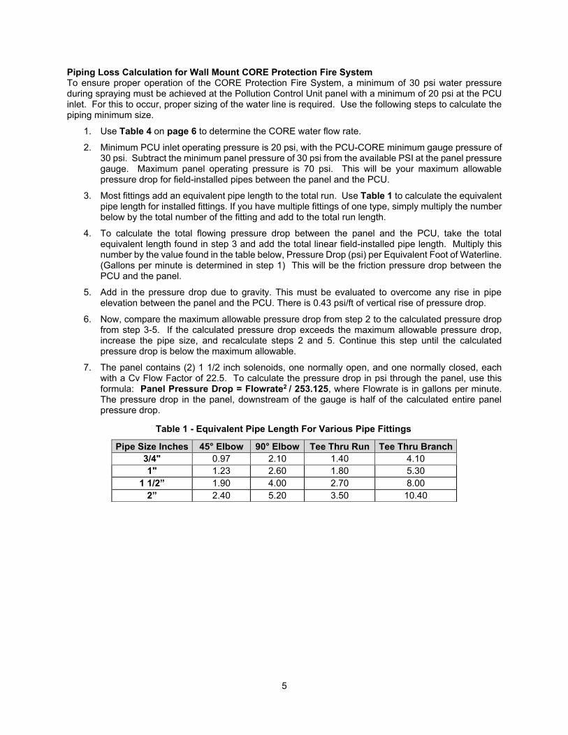
Piping Loss Calculation for Wall Mount CORE Protection Fire System To ensure proper operation of the CORE Protection Fire System, a minimum of 30 psi water pressure during spraying must be achieved at the Pollution Control Unit panel with a minimum of 20 psi at the PCU inlet. For this to occur, proper sizing of the water line is required. Use the following steps to calculate the piping minimum size.
1. Use Table 4 on page 6 to determine the CORE water flow rate.
2. Minimum PCU inlet operating pressure is 20 psi, with the PCU-CORE minimum gauge pressure of 30 psi. Subtract the minimum panel pressure of 30 psi from the available PSI at the panel pressure gauge. Maximum panel operating pressure is 70 psi. This will be your maximum allowable pressure drop for field-installed pipes between the panel and the PCU.
3. Most fittings add an equivalent pipe length to the total run. Use Table 1 to calculate the equivalent pipe length for installed fittings. If you have multiple fittings of one type, simply multiply the number below by the total number of the fitting and add to the total run length.
4. To calculate the total flowing pressure drop between the panel and the PCU, take the total equivalent length found in step 3 and add the total linear field-installed pipe length. Multiply this number by the value found in the table below, Pressure Drop (psi) per Equivalent Foot of Waterline. (Gallons per minute is determined in step 1) This will be the friction pressure drop between the PCU and the panel.
5. Add in the pressure drop due to gravity. This must be evaluated to overcome any rise in pipe elevation between the panel and the PCU. There is 0.43 psi/ft of vertical rise of pressure drop.
6. Now, compare the maximum allowable pressure drop from step 2 to the calculated pressure drop from step 3-5. If the calculated pressure drop exceeds the maximum allowable pressure drop, increase the pipe size, and recalculate steps 2 and 5. Continue this step until the calculated pressure drop is below the maximum allowable.
7. The panel contains (2) 1 1/2 inch solenoids, one normally open, and one normally closed, each with a Cv Flow Factor of 22.5. To calculate the pressure drop in psi through the panel, use this formula: Panel Pressure Drop = Flowrate2 / 253.125, where Flowrate is in gallons per minute. The pressure drop in the panel, downstream of the gauge is half of the calculated entire panel pressure drop.
Table 1 - Equivalent Pipe Length For Various Pipe Fittings
Pipe Size Inches 45° Elbow 90° Elbow Tee Thru Run Tee Thru Branch 3/4" 0.97 2.10 1.40 4.10 1" 1.23 2.60 1.80 5.30
1 1/2” 1.90 4.00 2.70 8.00 2” 2.40 5.20 3.50 10.40
Table 1
6
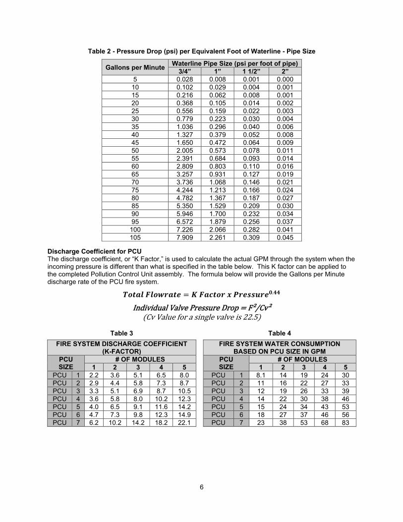
Table 2 - Pressure Drop (psi) per Equivalent Foot of Waterline - Pipe Size
Discharge Coefficient for PCU The discharge coefficient, or “K Factor,” is used to calculate the actual GPM through the system when the incoming pressure is different than what is specified in the table below. This K factor can be applied to the completed Pollution Control Unit assembly. The formula below will provide the Gallons per Minute discharge rate of the PCU fire system.
𝑻𝒐𝒕𝒂𝒍 𝑭𝒍𝒐𝒘𝒓𝒂𝒕𝒆 = 𝑲 𝑭𝒂𝒄𝒕𝒐𝒓 𝒙 𝑷𝒓𝒆𝒔𝒔𝒖𝒓𝒆𝟎.𝟒𝟒 Individual Valve Pressure Drop = F²/Cv²
(Cv Value for a single valve is 22.5)
Table 3 Table 4 FIRE SYSTEM DISCHARGE COEFFICIENT
(K-FACTOR) FIRE SYSTEM WATER CONSUMPTION
BASED ON PCU SIZE IN GPM PCU SIZE
# OF MODULES PCU SIZE
# OF MODULES 1 2 3 4 5 1 2 3 4 5
PCU 1 2.2 3.6 5.1 6.5 8.0 PCU 1 8.1 14 19 24 30 PCU 2 2.9 4.4 5.8 7.3 8.7 PCU 2 11 16 22 27 33 PCU 3 3.3 5.1 6.9 8.7 10.5 PCU 3 12 19 26 33 39 PCU 4 3.6 5.8 8.0 10.2 12.3 PCU 4 14 22 30 38 46 PCU 5 4.0 6.5 9.1 11.6 14.2 PCU 5 15 24 34 43 53 PCU 6 4.7 7.3 9.8 12.3 14.9 PCU 6 18 27 37 46 56 PCU 7 6.2 10.2 14.2 18.2 22.1 PCU 7 23 38 53 68 83
Gallons per Minute Waterline Pipe Size (psi per foot of pipe) 3/4” 1” 1 1/2” 2”
5 0.028 0.008 0.001 0.000 10 0.102 0.029 0.004 0.001 15 0.216 0.062 0.008 0.001 20 0.368 0.105 0.014 0.002 25 0.556 0.159 0.022 0.003 30 0.779 0.223 0.030 0.004 35 1.036 0.296 0.040 0.006 40 1.327 0.379 0.052 0.008 45 1.650 0.472 0.064 0.009 50 2.005 0.573 0.078 0.011 55 2.391 0.684 0.093 0.014 60 2.809 0.803 0.110 0.016 65 3.257 0.931 0.127 0.019 70 3.736 1.068 0.146 0.021 75 4.244 1.213 0.166 0.024 80 4.782 1.367 0.187 0.027 85 5.350 1.529 0.209 0.030 90 5.946 1.700 0.232 0.034 95 6.572 1.879 0.256 0.037
100 7.226 2.066 0.282 0.041 105 7.909 2.261 0.309 0.045

7
Field Pipe Pressure Drop Calculation Example: Wall mount panel installed with 30 feet of 3/4” linear pipe between panel and unit. There are two 90 degree elbows installed in the pipe run, and the pipe run has a vertical rise of 15 feet. A size 6 PF-HE-HE-OC-OC Pollution Control Unit is attached to the package.
Size 6 PCU-PF-HE-HE-OC-OC (5 modules) = 56 gpm Operating pressure required at PCU = 20 psi. Operating pressure at panel gauge = 50 psi. Allowable pressure drop between panel gauge and unit: 50 psi – 20 psi = 30 psi Equivalent length of pipe = 30 + 2 * 2.10 = 34.20 feet Friction Pressure Drop through pipe = 34.20 * 2.809 = 96.07 psi Gravitational Pressure = 0.43 psi/ft * 15 feet = 6.45 psi Panel pressure drop downstream of gauge = (56 gpm2 / 253.125) / 2 = 6.19 psi Total Pressure Drop in Field Pipe between panel gauge and unit = 96.07 + 6.45 + 6.19 = 108.71 psi Allowable pressure drop = 30 psi
This system will not work correctly because calculated pressure drop is greater than allowable pressure drop. Pipe size will need to be change to 1-1/2 inch diameter. Re-calculate with 1 1/2 inch pipe instead of 3/4” pipe: Equivalent length of pipe = 30 + 2 * 4.00 = 38.00 feet Friction Pressure Drop through pipe = 38.00 * 0.110 = 4.18 psi Gravitational Pressure = 0.43 psi/ft * 15 feet = 6.45 psi Panel pressure drop downstream of gauge = (56 gpm2 / 253.125) / 2 = 6.19 psi Total Pressure Drop in Field Pipe between panel gauge and unit = 4.18 + 6.45 + 6.19 = 16.82 psi Allowable pressure drop = 30 psi
This system will work correctly because calculated pressure drop is less than allowable pressure drop. Pressure Loss Through Typical Water Pipe Chart
0.01
0.1
1
10
1 10 100 1000
Pre
ssu
re L
oss
(P
SI/F
t)
FLOW (GPM)
Pressure Loss Water Flow
3/4" pipe
1" Pipe
1 1/2" Pipe
2" Pipe

8
Electrical
Before connecting power to the control, read and understand the entire section of this document. As-built wiring diagrams are furnished with each control by the factory and are attached either to the door of the unit or provided with the paperwork packet.
Electrical wiring and connections should be done in accordance with local ordinances and the National Electric Code, ANSI/NFPA 70. Be sure the voltage and phase of the power supply and the wire amperage capacity is in accordance with the unit nameplate.
ATTENTION: LOW-VOLTAGE DC OR SIGNALING WIRE SHOULD BE ROUTED IN SEPARATE CONDUIT FROM ALL AC SOURCES.
1. Always disconnect power before working on or near this equipment. Lock and tag the disconnect switch or breaker to prevent accidental power-up.
2. 120V AC should be wired to terminals H1 and N1. H1 and N1 should not be connected to a shunt trip breaker.
3. The maximum distance between the Pollution Control Unit CORE Protection System and a Hood CORE Protection System is 1000 feet. Shielded twisted pair cable must be used for this connection.
4. Make certain that the power source is compatible with the requirements of your equipment. The system wiring schematic identifies the proper phase and voltage of the equipment.
5. Before connecting control to power source, verify power line wiring is de-energized. 6. Secure the power cable to prevent contact with sharp objects. 7. Do not kink power cable and never allow the cable to come in contact with oil, grease, hot surfaces,
or chemicals. 8. Pollution Control Unit mounted firestats will need to be wired. The firestats should be wired to
terminal blocks, as indicated on the wiring schematic. Verify connections on wiring schematic. 9. Before powering up the system, make sure that the interior of the control is free of loose debris or
shipping materials. 10. If any of the original internal wire supplied with the system must be replaced, it must be replaced
with type THHN wire or equivalent. 11. The battery must be plugged into the connector labeled J1 on the CORE printed circuit board after
wiring is complete. 12. It is recommended to use Belden #6320UL, 18 Gauge, plenum-rated wire for the supervised loop. 13. It is recommended to use Belden #88760 for the CORE interlock network and CAT-5 for Modbus
communications. 14. All exterior wiring connections to the PCU must be run inside liquid tight conduit. This includes the
supervised loop and airflow switch wiring.
WARNING!!
Disconnect power before installing or servicing control. High voltage electrical input is needed for this equipment. This work should be performed by a qualified electrician.
IMPORTANT!!
CORE Protection battery backup produces output power even when main power is disconnected from system. When performing major electrical service to the control, the battery backup must be disconnected then reconnected before commissioning.
Table 5 - Copper Wire Ampacity Wire Size
AWG Maximum
Amps 14 15 12 20 10 30 8 50 6 65 4 85
9
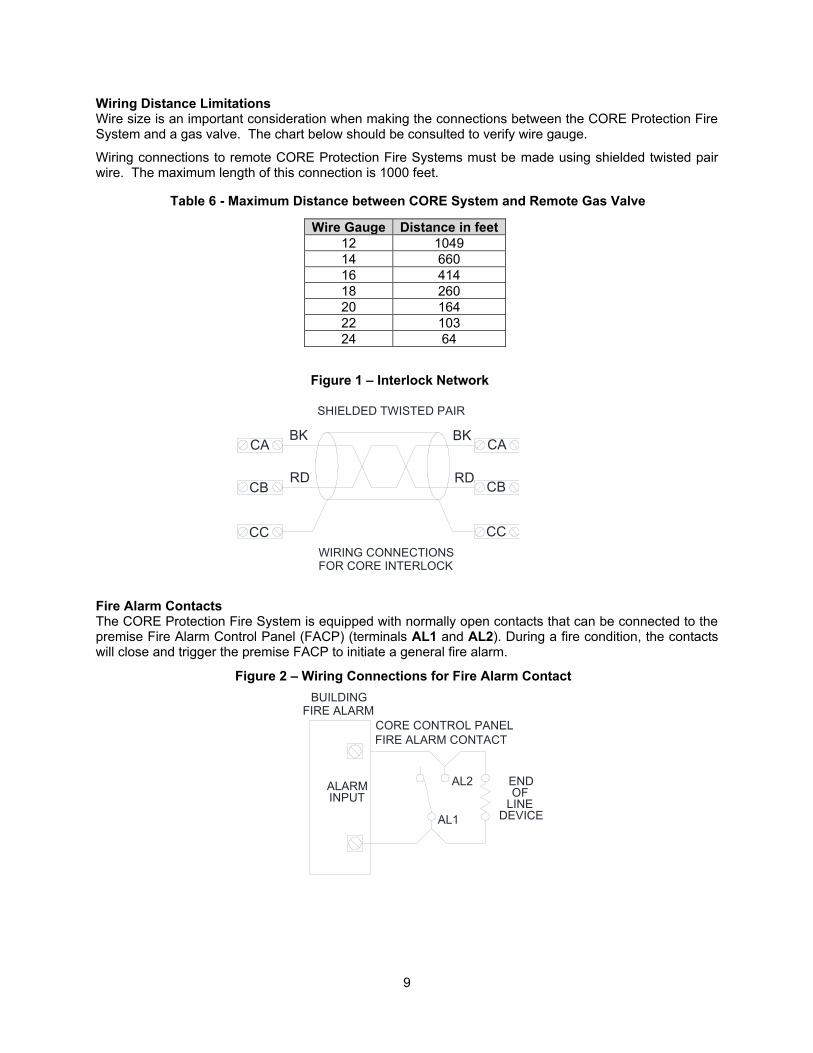
Wiring Distance Limitations Wire size is an important consideration when making the connections between the CORE Protection Fire System and a gas valve. The chart below should be consulted to verify wire gauge.
Wiring connections to remote CORE Protection Fire Systems must be made using shielded twisted pair wire. The maximum length of this connection is 1000 feet.
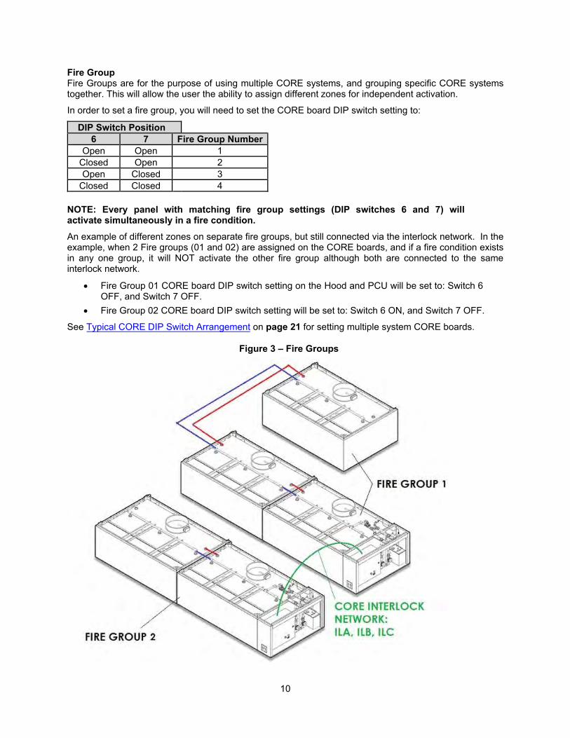
Fire Alarm Contacts The CORE Protection Fire System is equipped with normally open contacts that can be connected to the premise Fire Alarm Control Panel (FACP) (terminals AL1 and AL2). During a fire condition, the contacts will close and trigger the premise FACP to initiate a general fire alarm.
Wire Gauge Distance in feet 12 1049 14 660 16 414 18 260 20 164 22 103 24 64
Table 6 - Maximum Distance between CORE System and Remote Gas Valve
Figure 1 – Interlock Network
AL1
AL2 ENDOF
LINEDEVICE
ALARMINPUT
BUILDINGFIRE ALARM
CORE CONTROL PANELFIRE ALARM CONTACT
Figure 2 – Wiring Connections for Fire Alarm Contact
SHIELDED TWISTED PAIR
CA
CC
CB
CABK
CBRD
BK
RD
WIRING CONNECTIONSFOR CORE INTERLOCK
CC
10
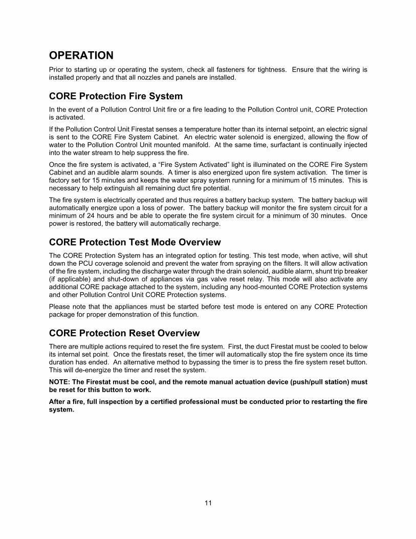
Fire Group Fire Groups are for the purpose of using multiple CORE systems, and grouping specific CORE systems together. This will allow the user the ability to assign different zones for independent activation.
In order to set a fire group, you will need to set the CORE board DIP switch setting to:
NOTE: Every panel with matching fire group settings (DIP switches 6 and 7) will activate simultaneously in a fire condition. An example of different zones on separate fire groups, but still connected via the interlock network. In the example, when 2 Fire groups (01 and 02) are assigned on the CORE boards, and if a fire condition exists in any one group, it will NOT activate the other fire group although both are connected to the same interlock network.
• Fire Group 01 CORE board DIP switch setting on the Hood and PCU will be set to: Switch 6 OFF, and Switch 7 OFF.
• Fire Group 02 CORE board DIP switch setting will be set to: Switch 6 ON, and Switch 7 OFF.
See Typical CORE DIP Switch Arrangement on page 21 for setting multiple system CORE boards.
DIP Switch Position 6 7 Fire Group Number
Open Open 1 Closed Open 2 Open Closed 3
Closed Closed 4
Figure 3 – Fire Groups
11
OPERATION Prior to starting up or operating the system, check all fasteners for tightness. Ensure that the wiring is installed properly and that all nozzles and panels are installed.
CORE Protection Fire System In the event of a Pollution Control Unit fire or a fire leading to the Pollution Control unit, CORE Protection is activated.
If the Pollution Control Unit Firestat senses a temperature hotter than its internal setpoint, an electric signal is sent to the CORE Fire System Cabinet. An electric water solenoid is energized, allowing the flow of water to the Pollution Control Unit mounted manifold. At the same time, surfactant is continually injected into the water stream to help suppress the fire.
Once the fire system is activated, a “Fire System Activated” light is illuminated on the CORE Fire System Cabinet and an audible alarm sounds. A timer is also energized upon fire system activation. The timer is factory set for 15 minutes and keeps the water spray system running for a minimum of 15 minutes. This is necessary to help extinguish all remaining duct fire potential.
The fire system is electrically operated and thus requires a battery backup system. The battery backup will automatically energize upon a loss of power. The battery backup will monitor the fire system circuit for a minimum of 24 hours and be able to operate the fire system circuit for a minimum of 30 minutes. Once power is restored, the battery will automatically recharge.
CORE Protection Test Mode Overview The CORE Protection System has an integrated option for testing. This test mode, when active, will shut down the PCU coverage solenoid and prevent the water from spraying on the filters. It will allow activation of the fire system, including the discharge water through the drain solenoid, audible alarm, shunt trip breaker (if applicable) and shut-down of appliances via gas valve reset relay. This mode will also activate any additional CORE package attached to the system, including any hood-mounted CORE Protection systems and other Pollution Control Unit CORE Protection systems.
Please note that the appliances must be started before test mode is entered on any CORE Protection package for proper demonstration of this function.
CORE Protection Reset Overview There are multiple actions required to reset the fire system. First, the duct Firestat must be cooled to below its internal set point. Once the firestats reset, the timer will automatically stop the fire system once its time duration has ended. An alternative method to bypassing the timer is to press the fire system reset button. This will de-energize the timer and reset the system.
NOTE: The Firestat must be cool, and the remote manual actuation device (push/pull station) must be reset for this button to work. After a fire, full inspection by a certified professional must be conducted prior to restarting the fire system.
12
CORE Protection Fire System Option Start Up Special Tools Required
• AC Voltage Meter • Standard Hand Tools • Hand-held Heat Source • Silicone Lubricant, Danco 88693
• Surfactant (Part Number WWDETER for 4 Gallons, WWDETER-1G for 1 Gallon)
• Supervised Loop Wire (Belden Part Number 6320UL or similar)
Jobsite Qualifications – Pre-installation CORE Protection Fire System
1. Verify the source for the CORE water supply (domestic or sprinkler), and determine the pressure drop from the connection at the source to the connection at the CORE manifold inlet.
2. Verify the proper amount of water pressure and flowrate is available for CORE Protection. Should the operating and static pressures exceed our maximum listing, correctly identify and size a pressure reducing valve.
3. Verify if a shutoff valve will be required on the CORE supply line.
Start Up Procedure – CORE Protection Fire System 1. Check all nozzles to make sure they are installed and tight. 2. Open the water valve to the control package. 3. Fill surfactant tank with surfactant. The “Add Surfactant” light should not be on. Prime the
surfactant pump with the push-button on the face of the control package. 4. The CORE Protection water connection must be a minimum 1-1/2” pipe and must be supervised.
This must be connected to a water supply line immediately downstream from the building's main shut-off valve or a water fire system. This main valve must be continuously supervised. If other appliances are connected to the CORE water supply line, those appliances must be operated during the CORE system testing and taken into consideration when calculating the size of the waterline pipe. Supply lines must be equipped with a strainer upstream of all CORE solenoid valves.
5. The fire system must be tested to ensure proper operation in the event of a fire. 6. Verify CORE Protection nozzle caps are easily removed. If nozzle caps stick on the nozzles during
a fire system discharge, apply silicone lubricant to the O-ring. Use Danco 88693 lubricant. 7. Ensure there are no supervision faults being reported by the “Fire System Activated” light and that
the light flashes one brief flash every 3 seconds, indicating the CORE system is armed and ready. 8. Ensure that the maximum water static pressure on the panel is less than 125 psi. 9. Verify the exterior conduit is liquid-tight.
NOTE: Activating a PCU CORE system will also activate any other CORE, PCU, or HOOD fire system that is connected to the same fire group. Ensure that all other systems are ready to be tested by placing the system panels in the test mode and ensuring hood filters and drains are in place.
13
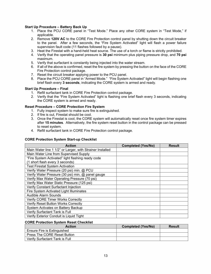
Start Up Procedure – Battery Back Up 1. Place the PCU CORE panel in “Test Mode.” Place any other CORE system in “Test Mode,” if
applicable. 2. Remove 120V AC to the CORE Fire Protection control panel by shutting down the circuit breaker
to the panel. After a few seconds, the “Fire System Activated” light will flash a power failure supervision fault code (11 flashes followed by a pause).
3. Heat the Firestat with a hand-held heat source. The use of a torch or flame is strictly prohibited. 4. Verify that the operating panel pressure is 30 psi minimum plus piping pressure drop, and 70 psi
maximum. 5. Verify that surfactant is constantly being injected into the water stream. 6. If all of the above is confirmed, reset the fire system by pressing the button on the face of the CORE
Fire Protection control package. 7. Reset the circuit breaker applying power to the PCU panel. 8. Place the PCU CORE panel in “Armed Mode.” “Fire System Activated” light will begin flashing one
brief flash every 3 seconds, indicating the CORE system is armed and ready.
Start Up Procedure – Final 1. Refill surfactant tank in CORE Fire Protection control package. 2. Verify that the “Fire System Activated” light is flashing one brief flash every 3 seconds, indicating
the CORE system is armed and ready.
Reset Procedure – CORE Protection Fire System 1. Fully inspect system to make sure fire is extinguished. 2. If fire is out, Firestat should be cool. 3. Once the Firestat is cool, the CORE system will automatically reset once fire system timer expires
after 15 minutes. Alternatively, the fire system reset button in the control package can be pressed to reset system.
4. Refill surfactant tank in CORE Fire Protection control package.
CORE Protection System Start-up Checklist
Action Completed (Yes/No) Result Main Water line 1 1/2” or Larger, with Strainer Installed Main Water Line from Supervised Supply “Fire System Activated” light flashing ready code (1 short flash every 3 seconds)
Test Firestat System Activation Verify Water Pressure (20 psi) min. @ PCU Verify Water Pressure (30 psi) min, @ panel gauge Verify Max Water Operating Pressure (70 psi) Verify Max Water Static Pressure (125 psi) Verify Constant Surfactant Injection Fire System Activated Light Illuminates Audible Alarm Sounds Verify CORE Timer Works Correctly Verify Reset Button Works Correctly System Activates on Battery Backup Verify Surfactant Tank is Full Verify Exterior Conduit is Liquid Tight
CORE Protection System Reset Checklist Action Completed (Yes/No) Result
Ensure Fire is Extinguished Press The CORE Reset Button Verify Surfactant Tank is Full

14
Component Description The following section lists the major controls and components used in the Pollution Control Unit CORE Protection fire system.
Water Manifold The Pollution Control Unit CORE Fire Protecton System package consists of two normally open valves and one normally closed valve. A strainer is to be installed upstream of all solenoid valves.
1. All fittings and piping will be brass except for drain components. 2. Length and width of manifold must match measurements listed on this page. 3. All pipe nipples are closed unless otherwise noted. 4. Valves can be rotated for best fit inside cabinet. 5. Optional slow-close solenoid part # SC8221G011-24DC may be used as an alternative. 6. Strainer to be shipped loose, installed in field upstream of solenoids.
28 7/16"±1/2"
SurfactantInjectionPoint
Use part AQ2593to clampmanifold down.
Use part AQ2593to clampmanifold down.
5
13
14
2
16
1
4
3
8
26
27
28 25
29
22
19
22
2318
1115
1012
18
11
17
20
6
7
9
17
24
18
Figure 4 – Water Manifold Components
15
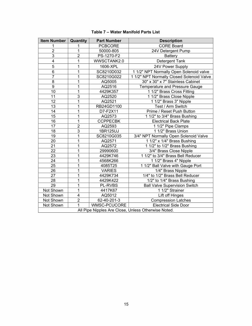
Item Number Quantity Part Number Description 1 1 PCBCORE CORE Board 2 1 50000-805 24V Detergent Pump 3 2 PS-1270-F2 Battery 4 1 WWSCTANK2.0 Detergent Tank 5 1 1606-XPL 24V Power Supply 6 1 SC8210D032 1 1/2" NPT Normally Open Solenoid valve 7 1 SC8210G022 1 1/2" NPT Normally Closed Solenoid Valve 8 1 AQ5005 30" x 30" x 7" Stainless Cabinet 9 1 AQ2516 Temperature and Pressure Gauge 10 1 4429K357 1 1/2" Brass Cross Fitting 11 3 AQ2520 1 1/2" Brass Close Nipple 12 1 AQ2521 1 1/2" Brass 3" Nipple 13 1 RB24GD1100 Test / Arm Switch 14 1 D7-F2X11 Prime / Reset Push Button 15 1 AQ2573 1 1/2" to 3/4" Brass Bushing 16 1 CCPPECBK Electrical Back Plate 17 2 AQ2593 1 1/2" Pipe Clamps 18 3 1BR125UJ 1 1/2" Brass Union 19 1 SC8210G035 3/4" NPT Normally Open Solenoid Valve 20 1 AQ2571 1 1/2" x 1/4" Brass Bushing 21 1 AQ2572 1 1/2" to 1/2" Brass Bushing 22 1 29990600 3/4" Brass Close Nipple 23 1 4429K746 1 1/2" to 3/4" Brass Bell Reducer 24 1 4568K266 1 1/2" Brass 4" Nipple 25 1 4085T25 1 1/2" Ball Valve with Gauge Port 26 1 VARIES 1/4" Brass Nipple 27 1 4429K734 1/4" to 1/2" Brass Bell Reducer 28 1 4429K422 1/2" to 1/4" Brass Bushing 29 1 PL-RVBS Ball Valve Supervision Switch
Not Shown 1 4417K67 1 1/2" Strainer Not Shown 4 AQ5012 Lift off Hinges Not Shown 2 62-40-201-3 Compression Latches Not Shown 1 WMSC-PCUCORE Electrical Side Door
All Pipe Nipples Are Close, Unless Otherwise Noted.
Table 7 – Water Manifold Parts List
16
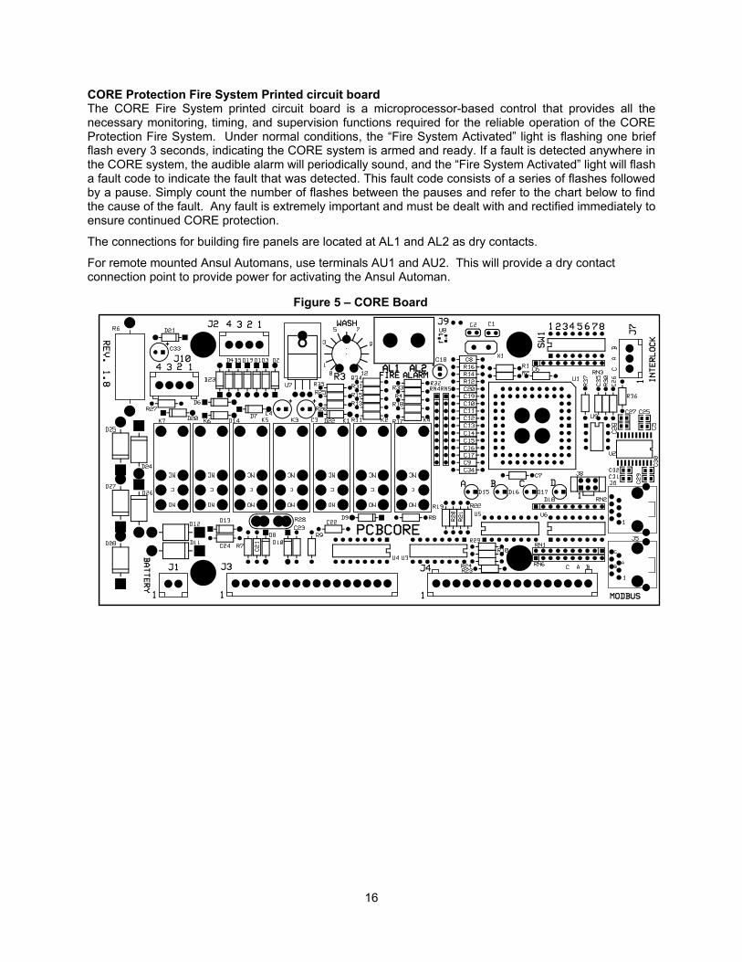
CORE Protection Fire System Printed circuit board The CORE Fire System printed circuit board is a microprocessor-based control that provides all the necessary monitoring, timing, and supervision functions required for the reliable operation of the CORE Protection Fire System. Under normal conditions, the “Fire System Activated” light is flashing one brief flash every 3 seconds, indicating the CORE system is armed and ready. If a fault is detected anywhere in the CORE system, the audible alarm will periodically sound, and the “Fire System Activated” light will flash a fault code to indicate the fault that was detected. This fault code consists of a series of flashes followed by a pause. Simply count the number of flashes between the pauses and refer to the chart below to find the cause of the fault. Any fault is extremely important and must be dealt with and rectified immediately to ensure continued CORE protection.
The connections for building fire panels are located at AL1 and AL2 as dry contacts.
For remote mounted Ansul Automans, use terminals AU1 and AU2. This will provide a dry contact connection point to provide power for activating the Ansul Automan.
Figure 5 – CORE Board
17
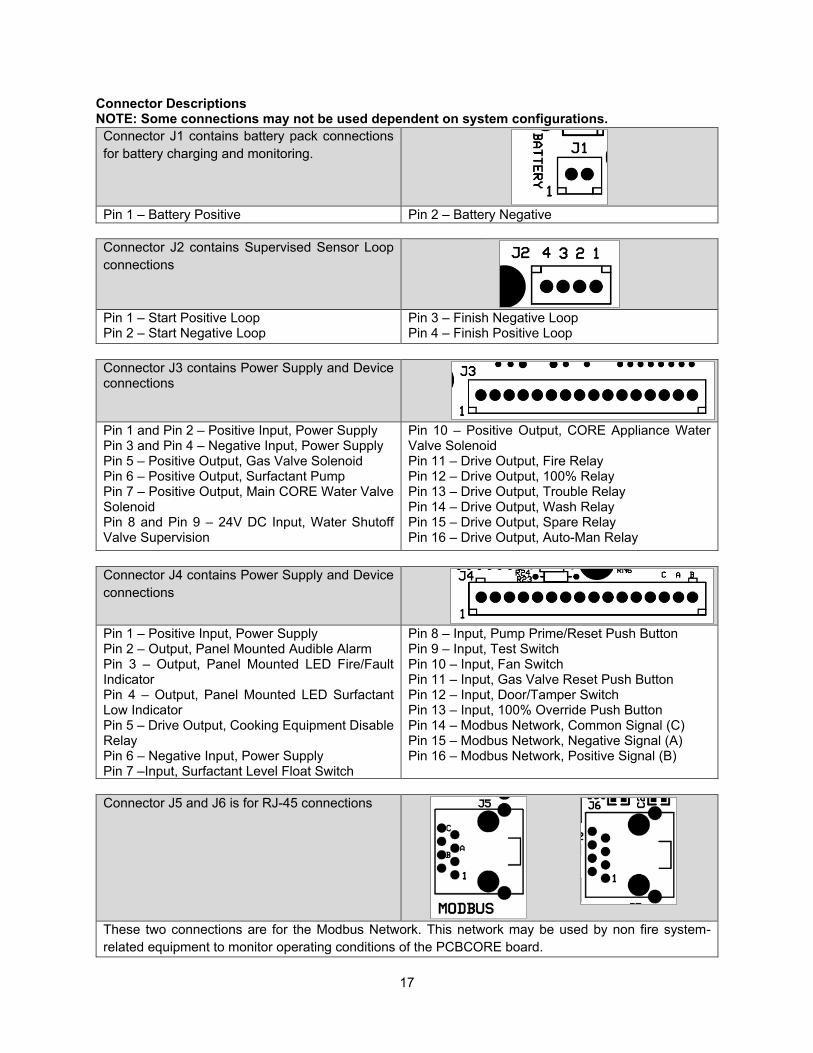
Connector Descriptions NOTE: Some connections may not be used dependent on system configurations.
Connector J1 contains battery pack connections for battery charging and monitoring.
Pin 1 – Battery Positive Pin 2 – Battery Negative
Connector J2 contains Supervised Sensor Loop connections
Pin 1 – Start Positive Loop Pin 2 – Start Negative Loop
Pin 3 – Finish Negative Loop Pin 4 – Finish Positive Loop
Connector J3 contains Power Supply and Device connections
Pin 1 and Pin 2 – Positive Input, Power Supply Pin 3 and Pin 4 – Negative Input, Power Supply Pin 5 – Positive Output, Gas Valve Solenoid Pin 6 – Positive Output, Surfactant Pump Pin 7 – Positive Output, Main CORE Water Valve Solenoid Pin 8 and Pin 9 – 24V DC Input, Water Shutoff Valve Supervision
Pin 10 – Positive Output, CORE Appliance Water Valve Solenoid Pin 11 – Drive Output, Fire Relay Pin 12 – Drive Output, 100% Relay Pin 13 – Drive Output, Trouble Relay Pin 14 – Drive Output, Wash Relay Pin 15 – Drive Output, Spare Relay Pin 16 – Drive Output, Auto-Man Relay
Connector J4 contains Power Supply and Device connections
Pin 1 – Positive Input, Power Supply Pin 2 – Output, Panel Mounted Audible Alarm Pin 3 – Output, Panel Mounted LED Fire/Fault Indicator Pin 4 – Output, Panel Mounted LED Surfactant Low Indicator Pin 5 – Drive Output, Cooking Equipment Disable Relay Pin 6 – Negative Input, Power Supply Pin 7 –Input, Surfactant Level Float Switch
Pin 8 – Input, Pump Prime/Reset Push Button Pin 9 – Input, Test Switch Pin 10 – Input, Fan Switch Pin 11 – Input, Gas Valve Reset Push Button Pin 12 – Input, Door/Tamper Switch Pin 13 – Input, 100% Override Push Button Pin 14 – Modbus Network, Common Signal (C) Pin 15 – Modbus Network, Negative Signal (A) Pin 16 – Modbus Network, Positive Signal (B)
Connector J5 and J6 is for RJ-45 connections
These two connections are for the Modbus Network. This network may be used by non fire system-related equipment to monitor operating conditions of the PCBCORE board.
18
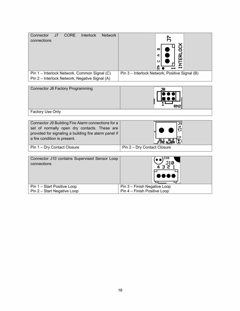
Connector J7 CORE Interlock Network connections
Pin 1 – Interlock Network, Common Signal (C) Pin 2 – Interlock Network, Negative Signal (A)
Pin 3 – Interlock Network, Positive Signal (B)
Connector J8 Factory Programming
Factory Use Only
Connector J9 Building Fire Alarm connections for a set of normally open dry contacts. These are provided for signaling a building fire alarm panel if a fire condition is present.
Pin 1 – Dry Contact Closure Pin 2 – Dry Contact Closure
Connector J10 contains Supervised Sensor Loop connections
Pin 1 – Start Positive Loop Pin 2 – Start Negative Loop
Pin 3 – Finish Negative Loop Pin 4 – Finish Positive Loop

19
Table 8 – CORE Board Faults Catastrophic faults
Number of flashes
Fault condition Corrective Action
2 CORE water solenoid
Check solenoid and wiring to solenoid, replace as needed
3 Drain solenoid Check solenoid and wiring to solenoid, replace as needed 4 Auxiliary Fault Check supervised Pressure Regulating Valves (optional) and
Pressure Switches (optional). 5 Microcontroller
fault Replace CORE printed circuit board
Critical faults Number of
flashes Fault condition Corrective Action
6 CORE surfactant pump
Check surfactant pump motor and wiring to the motor, replace as needed
7 Supervised Loop Check the wiring to all the manual actuation devices (push/pull stations) and fire sensors for loose connections, replace as needed
Important faults Number of
flashes Fault condition Corrective Action
8 Ground Fault Check the wiring to all the manual actuation devices (push/pull stations) and fire sensors for shorts to ground, replace as needed
9 Surfactant Low Add surfactant, check/replace float switch 10 Battery voltage low Replace batteries, wait for batteries to recharge if there was a
power failure 11 AC power failure Check breakers, call power company 12 Door tamper switch Close cabinet door 13 PCU Test mode Place switch in armed position when testing is complete. 14 CORE Interlock Check DIP Switches on all Boards and RS-485 Network
Wires connecting boards 15 Fault on hood in
network Check all hoods in CORE network for faults
16 Fault on PCU in network
Check all PCUs in CORE network for faults
20
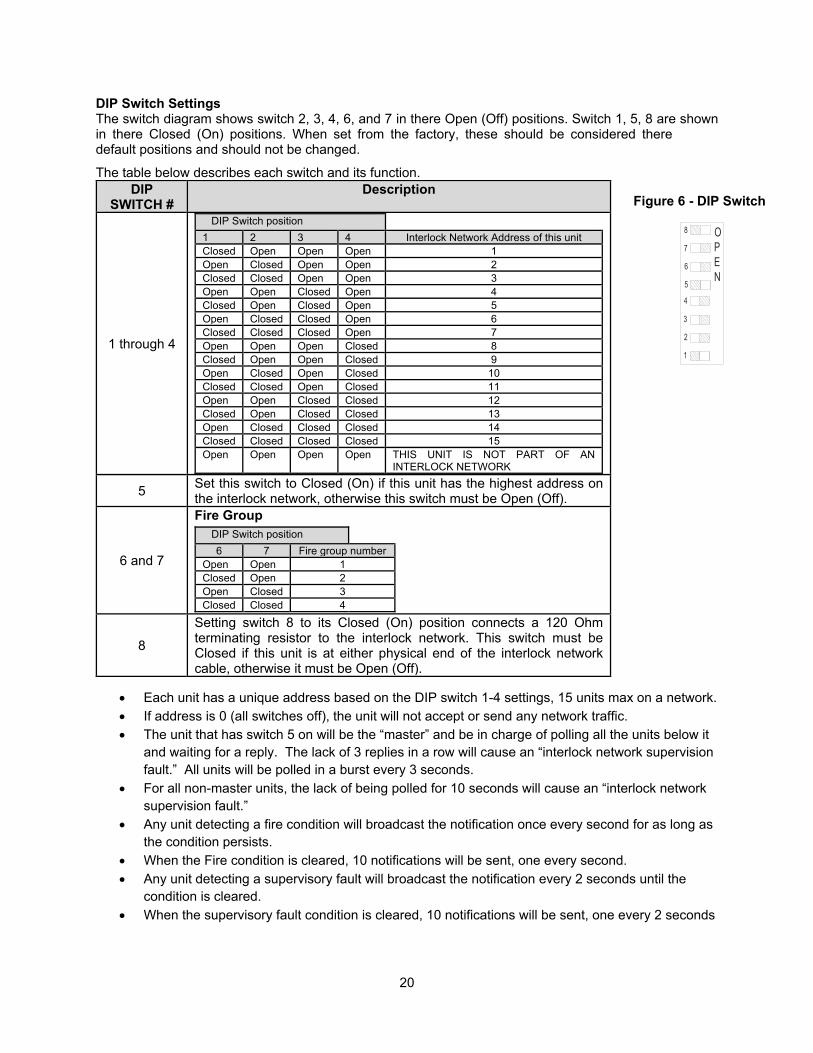
DIP Switch Settings The switch diagram shows switch 2, 3, 4, 6, and 7 in there Open (Off) positions. Switch 1, 5, 8 are shown in there Closed (On) positions. When set from the factory, these should be considered there default positions and should not be changed.
The table below describes each switch and its function.
• Each unit has a unique address based on the DIP switch 1-4 settings, 15 units max on a network.• If address is 0 (all switches off), the unit will not accept or send any network traffic.• The unit that has switch 5 on will be the “master” and be in charge of polling all the units below it
and waiting for a reply. The lack of 3 replies in a row will cause an “interlock network supervision fault.” All units will be polled in a burst every 3 seconds.
• For all non-master units, the lack of being polled for 10 seconds will cause an “interlock network supervision fault.”
• Any unit detecting a fire condition will broadcast the notification once every second for as long as the condition persists.
• When the Fire condition is cleared, 10 notifications will be sent, one every second.• Any unit detecting a supervisory fault will broadcast the notification every 2 seconds until the
condition is cleared.• When the supervisory fault condition is cleared, 10 notifications will be sent, one every 2 seconds
DIP SWITCH #
Description
1 through 4
DIP Switch position
1 2 3 4 Interlock Network Address of this unit Closed Open Open Open 1
Open Closed Open Open 2
Closed Closed Open Open 3
Open Open Closed Open 4
Closed Open Closed Open 5
Open Closed Closed Open 6
Closed Closed Closed Open 7
Open Open Open Closed 8
Closed Open Open Closed 9
Open Closed Open Closed 10
Closed Closed Open Closed 11
Open Open Closed Closed 12
Closed Open Closed Closed 13
Open Closed Closed Closed 14
Closed Closed Closed Closed 15
Open Open Open Open THIS UNIT IS NOT PART OF AN INTERLOCK NETWORK
5 Set this switch to Closed (On) if this unit has the highest address on the interlock network, otherwise this switch must be Open (Off).
6 and 7
Fire Group DIP Switch position
6 7 Fire group number Open Open 1
Closed Open 2
Open Closed 3
Closed Closed 4
8
Setting switch 8 to its Closed (On) position connects a 120 Ohm terminating resistor to the interlock network. This switch must be Closed if this unit is at either physical end of the interlock network cable, otherwise it must be Open (Off).
1
2
3
4
5
6
7
8 OPEN
Figure 6 - DIP Switch
21
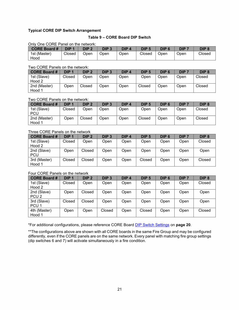
Typical CORE DIP Switch Arrangement Table 9 – CORE Board DIP Switch
Only One CORE Panel on the network: CORE Board # DIP 1 DIP 2 DIP 3 DIP 4 DIP 5 DIP 6 DIP 7 DIP 8 1st (Master) Hood
Closed Open Open Open Closed Open Open Closed
Two CORE Panels on the network: CORE Board # DIP 1 DIP 2 DIP 3 DIP 4 DIP 5 DIP 6 DIP 7 DIP 8 1st (Slave) Hood 2
Closed Open Open Open Open Open Open Closed
2nd (Master) Hood 1
Open Closed Open Open Closed Open Open Closed
Two CORE Panels on the network: CORE Board # DIP 1 DIP 2 DIP 3 DIP 4 DIP 5 DIP 6 DIP 7 DIP 8 1st (Slave) PCU
Closed Open Open Open Open Open Open Closed
2nd (Master) Hood 1
Open Closed Open Open Closed Open Open Closed
Three CORE Panels on the network CORE Board # DIP 1 DIP 2 DIP 3 DIP 4 DIP 5 DIP 6 DIP 7 DIP 8 1st (Slave) Hood 2
Closed Open Open Open Open Open Open Closed
2nd (Slave) PCU
Open Closed Open Open Open Open Open Open
3rd (Master) Hood 1
Closed Closed Open Open Closed Open Open Closed
Four CORE Panels on the network CORE Board # DIP 1 DIP 2 DIP 3 DIP 4 DIP 5 DIP 6 DIP 7 DIP 8 1st (Slave) Hood 2
Closed Open Open Open Open Open Open Closed
2nd (Slave) PCU 2
Open Closed Open Open Open Open Open Open
3rd (Slave) PCU 1
Closed Closed Open Open Open Open Open Open
4th (Master) Hood 1
Open Open Closed Open Closed Open Open Closed
*For additional configurations, please reference CORE Board DIP Switch Settings on page 20.
**The configurations above are shown with all CORE boards in the same Fire Group and may be configured differently, even if the CORE panels are on the same network. Every panel with matching fire group settings (dip switches 6 and 7) will activate simultaneously in a fire condition.
22
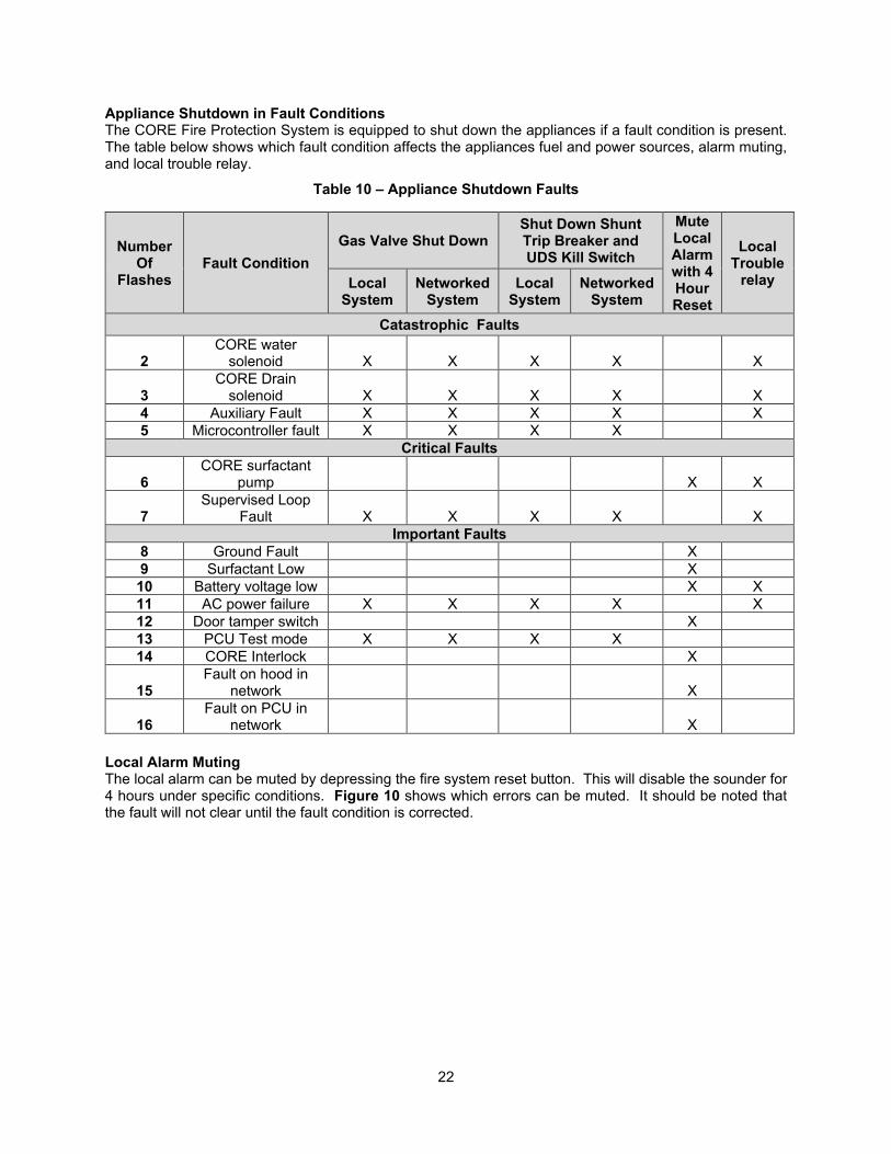
Appliance Shutdown in Fault Conditions The CORE Fire Protection System is equipped to shut down the appliances if a fault condition is present. The table below shows which fault condition affects the appliances fuel and power sources, alarm muting, and local trouble relay.
Table 10 – Appliance Shutdown Faults
Number Of
Flashes Fault Condition
Gas Valve Shut Down Shut Down Shunt Trip Breaker and UDS Kill Switch
Mute Local Alarm with 4 Hour Reset
Local Trouble
relay Local System
Networked System
Local System
Networked System
Catastrophic Faults
2 CORE water
solenoid X X X X X
3 CORE Drain
solenoid X X X X X 4 Auxiliary Fault X X X X X 5 Microcontroller fault X X X X
Critical Faults
6 CORE surfactant
pump X X
7 Supervised Loop
Fault X X X X X Important Faults
8 Ground Fault X 9 Surfactant Low X 10 Battery voltage low X X 11 AC power failure X X X X X 12 Door tamper switch X 13 PCU Test mode X X X X 14 CORE Interlock X
15 Fault on hood in
network X
16 Fault on PCU in
network X
Local Alarm Muting The local alarm can be muted by depressing the fire system reset button. This will disable the sounder for 4 hours under specific conditions. Figure 10 shows which errors can be muted. It should be noted that the fault will not clear until the fault condition is corrected.

23
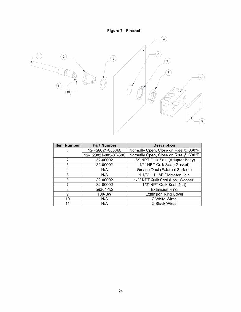
CORE Protection Firestat The Firestat is a device installed in the riser of the hood, at the duct connection, that measures temperature. The standard temperature setting is 360°F. Depending on heat produced by appliance, a higher rated temperature Firestat will be required. If a temperature higher than the setpoint is sensed, the Firestat contacts will close and energize the electrical control board. The fire system will activate, the system will run for a minimum of 15 minutes and then recheck the temperature. If the temperature is still higher than the setpoint, the process restarts immediately.
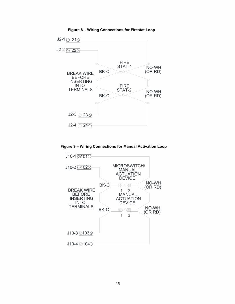
The Firestat has 2 black wires and 2 white wires, these wires must be connected into the supervised loop. Use high-temperature wiring when installing Firestat components. High-temperature wire-nuts or terminal blocks must be used. There must be one sensor installed for every 12 feet of hood length.
Multiple sensors are wired in parallel in the supervised loop. The Firestat may be installed on the opposite side of the quick seal for access in the duct.
Non-Solid Fuel Appliances (Rated 450°F) Non-solid fuel appliances rated for 450°F will not require additional firestats, regardless of the configuration and length of ductwork.
Non-Solid Fuel Appliances (Rated 600°F) Non-solid fuel appliances rated for 600°F will require downstream detection if the duct run contains any horizontal section over 10 feet in length. Downstream detection should be installed at the end of a horizontal section. Duct layouts that include less than 10 feet of horizontal ductwork will not require additional detection.
Solid Fuel Appliances (Rated 700°F) Solid fuel appliances produce effluents that can accumulate inside the duct, especially in long horizontal duct runs. Sparks from solid fuel appliances can travel into the ductwork and create fires that occur beyond the point where the hood riser Firestat can detect them. Additional downstream Firestats ensure that these duct fires are detected, and the fire system actuates. Solid fuel applications require 600°F rated Firestats, and SOLO filters.
In addition to the 600°F rated Firestat, located in the hood riser, a second Firestat is required at the duct discharge for solid fuel applications when the ductwork exceeds 10 feet in length or contains horizontal runs. Even if the entire duct run is inaccessible, this additional Firestat is still needed. Mounting a Firestat in the fan may be an option. On duct runs longer than 50 feet, a third Firestat will be required somewhere in the duct run, ideally at the end of a horizontal run, if present. Duct runs longer than 100 feet will require additional Firestats, contact Factory Service Department for more information.
NOTE: When additional Firestats are required, install in an accessible location near an access door, hood riser, or fan. The door will provide access to install, clean, and replace the Firestat when needed. If a PCU is equipped with electronic detection, PCU Firestats can serve as downstream detectors, if present. The temperature rating of the Firestat in the duct must always match the temperature rating of the Firestat in the riser.
24
1 2
4
5
7
6
8
9
3
10
11
Figure 7 - Firestat
Item Number Part Number Description
1 12-F28021-005360 Normally Open, Close on Rise @ 360°F 12-H28021-005-0T-600 Normally Open, Close on Rise @ 600°F
2 32-00002 1/2” NPT Quik Seal (Adapter Body) 3 32-00002 1/2” NPT Quik Seal (Gasket) 4 N/A Grease Duct (External Surface) 5 N/A 1 1/8” – 1 1/4” Diameter Hole 6 32-00002 1/2” NPT Quik Seal (Lock Washer) 7 32-00002 1/2” NPT Quik Seal (Nut) 8 59361-1/2 Extension Ring 9 100-BW Extension Ring Cover 10 N/A 2 White Wires 11 N/A 2 Black Wires
25
BK-C
BK-C
21
22
23
24
J2-1
J2-2
J2-4
J2-3
FIRESTAT-2
FIRESTAT-1 NO-WH
(OR RD)
NO-WH(OR RD)
BREAK WIREBEFORE
INSERTINGINTO
TERMINALS
Figure 8 – Wiring Connections for Firestat Loop
BK-C
101
102
103
104
J10-1
J10-2
J10-4
J10-3
BK-C
BREAK WIREBEFORE
INSERTINGINTO
TERMINALS
NO-WH(OR RD)
MANUALACTUATION
DEVICE
NO-WH(OR RD)
MANUALACTUATION
DEVICE
MICROSWITCH/
Figure 9 – Wiring Connections for Manual Activation Loop

26
Surfactant Tank CORE Protection fire system utilizes a two-gallon surfactant tank. For this package, the low-level control is located at the 1-gallon mark. In the event of a fire, surfactant is continuously injected into the water spray to help suppress the fire. One gallon of surfactant will last for approximately 15 minutes of fire protection. In the event that the low-level sensor is activated, an “Add Surfactant” light will illuminate on the control panel. To reset light, simply fill the surfactant tank with surfactant. Figure 10 shows tank details.
NOTE: SC-5 surfactant from 20/10 Products Incorporated must be used. Lift the front lid to fill the tank, fill to top.
Figure 10 – Surfactant Tank Details
Callout Description Part Number 1 Rear Lid WWSTRLID 2 7/8” Grommet N/A 3 Spring Hinge 531944-0104 4 Tank Side WWSTSIDE 5 Tank Body WWSTBODY 6 Front Lid WWSTFLID 7 1/2” Quick Seal 32-00002 8 2” x 1/2” Brass Nipple 4568K173 9 1/2” to 1/8” Reducing Coupling 4429K733 10 Level Switch AQ5510
6"
9"
9 1/4"
10"
1
2
3
4
5
6
7
8
9
10
27
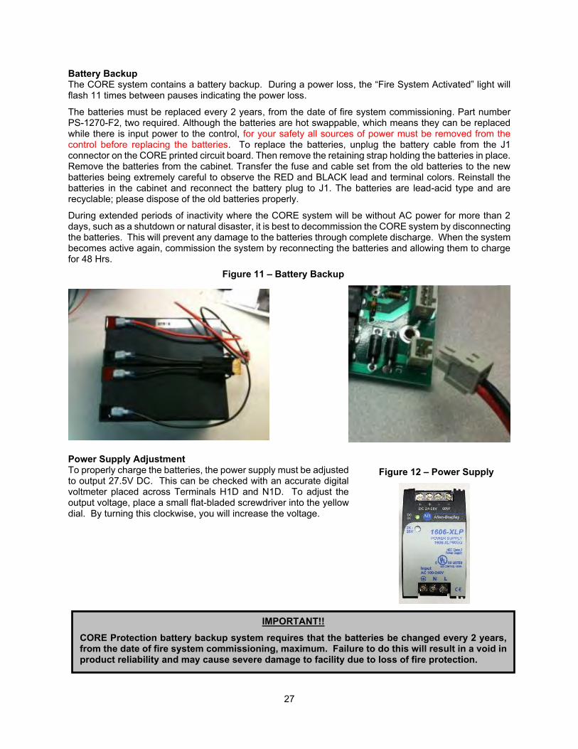
Battery Backup The CORE system contains a battery backup. During a power loss, the “Fire System Activated” light will flash 11 times between pauses indicating the power loss.
The batteries must be replaced every 2 years, from the date of fire system commissioning. Part number PS-1270-F2, two required. Although the batteries are hot swappable, which means they can be replaced while there is input power to the control, for your safety all sources of power must be removed from the control before replacing the batteries. To replace the batteries, unplug the battery cable from the J1 connector on the CORE printed circuit board. Then remove the retaining strap holding the batteries in place. Remove the batteries from the cabinet. Transfer the fuse and cable set from the old batteries to the new batteries being extremely careful to observe the RED and BLACK lead and terminal colors. Reinstall the batteries in the cabinet and reconnect the battery plug to J1. The batteries are lead-acid type and are recyclable; please dispose of the old batteries properly.
During extended periods of inactivity where the CORE system will be without AC power for more than 2 days, such as a shutdown or natural disaster, it is best to decommission the CORE system by disconnecting the batteries. This will prevent any damage to the batteries through complete discharge. When the system becomes active again, commission the system by reconnecting the batteries and allowing them to charge for 48 Hrs.
Power Supply Adjustment To properly charge the batteries, the power supply must be adjusted to output 27.5V DC. This can be checked with an accurate digital voltmeter placed across Terminals H1D and N1D. To adjust the output voltage, place a small flat-bladed screwdriver into the yellow dial. By turning this clockwise, you will increase the voltage.
Figure 12 – Power Supply
IMPORTANT!!
CORE Protection battery backup system requires that the batteries be changed every 2 years, from the date of fire system commissioning, maximum. Failure to do this will result in a void in product reliability and may cause severe damage to facility due to loss of fire protection.
Figure 11 – Battery Backup
28
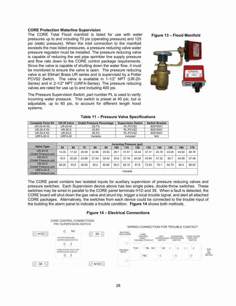
CORE Protection Waterline Supervision The CORE Total Flood manifold is listed for use with water pressures up to and including 70 psi (operating pressure) and 125 psi (static pressure). When the inlet connection to the manifold exceeds the max listed pressures, a pressure reducing valve water pressure regulator must be installed. The pressure reducing valve is capable of reducing the wet pipe sprinkler line supply pressure and flow rate down to the CORE control package requirements. Since the valve is capable of shutting down the water flow, it must be monitored to ensure the valve is open. The pressure reducing valve is an Elkhart Brass UR series and is supervised by a Potter PCVS2 Switch. The valve is available in 1-1/2” NPT (UR-20-Series) and in 2-1/2" NPT (URFA-Series). The pressure reducing valves are rated for use up to and including 400 psi.
The Pressure Supervision Switch, part number PL is used to verify incoming water pressure. This switch is preset at 40 psi, but is adjustable, up to 60 psi, to account for different length hood systems.
Table 11 – Pressure Valve Specifications Complete Parts Kit UR-20 Valve Outlet Pressure Percentage Supervision Switch Switch Bracket
UR-20-W Kit UR-20-W 28.7% PL-PCVS2 80574001 UR-20-X Kit UR-20-X 33.8% PL-PCVS2 80574001 UR-20-Z Kit UR-20-Z 56.5% PL-PCVS2 80574001 URFA-20-S URFA-20 Variable Included N/A
Valve Type
Incoming Pressure (psi) 50 60 70 80 90 100 110 120 130 140 150 160 170
UR-20-W (Outlet Pressure psi)
14.35 17.22 20.09 22.96 25.83 28.7 31.57 34.44 37.31 40.18 43.05 45.92 48.79
UR-20-X (Outlet Pressure psi)
16.9 20.28 23.66 27.04 30.42 33.8 37.18 40.56 43.94 47.32 50.7 54.08 57.46
UR-20-Z (Outlet Pressure psi)
28.25 33.9 39.55 45.2 50.85 56.5 62.15 67.8 73.45 79.1 84.75 90.4 96.05
URFA-20-S (Outlet Pressure psi)
Variable
The CORE panel contains two isolated inputs for auxiliary supervision of pressure reducing valves and pressure switches. Each Supervision device above has two single poles, double-throw switches. These switches may be wired in parallel to the CORE panel terminals H1D and 39. When a fault is detected, the CORE board will shut down the gas valve and shunt trip, trigger a local trouble signal, and alert all attached CORE packages. Alternatively, the switches from each device could be connected to the trouble input of the building fire alarm panel to indicate a trouble condition. Figure 14 shows both methods.
Figure 14 – Electrical Connections
Figure 13 – Flood Manifold
H1DC
C
C
NC
2
2
WATER PRESSURESUPERVISION SWITCH
CORE WATER SHUT-OFFSUPERVISION SWITCH
CORE CONTROL CONNECTIONSPRV SUPERVISION SWITCH
39
38 N1D
CORE WATERSHUT-OFF
SWITCH
1 2
C
BUILDINGFIRE ALARM
TROUBLEINPUT
CORECONTROLPANEL
TROUBLE CONTACT
NO
C
NC 1
C
2
PRVSUPERVISION
SWITCH
WATERLINESUPERVISION
SWITCH
ENDOF
LINEDEVICETBC
TBLTOK
WIRING CONNECTION FOR TROUBLE CONTACT
29
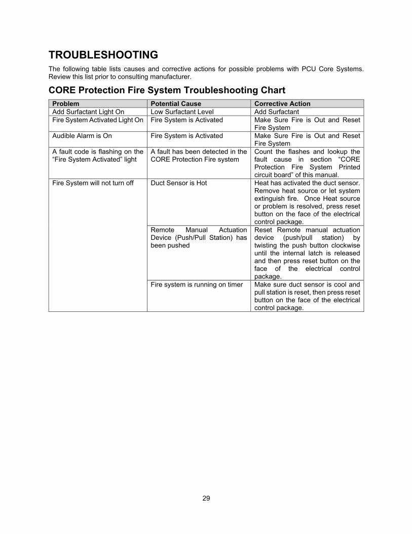
TROUBLESHOOTING The following table lists causes and corrective actions for possible problems with PCU Core Systems. Review this list prior to consulting manufacturer.
CORE Protection Fire System Troubleshooting Chart Problem Potential Cause Corrective Action Add Surfactant Light On Low Surfactant Level Add Surfactant Fire System Activated Light On Fire System is Activated Make Sure Fire is Out and Reset
Fire System Audible Alarm is On Fire System is Activated Make Sure Fire is Out and Reset
Fire System A fault code is flashing on the “Fire System Activated” light
A fault has been detected in the CORE Protection Fire system
Count the flashes and lookup the fault cause in section “CORE Protection Fire System Printed circuit board” of this manual.
Fire System will not turn off Duct Sensor is Hot Heat has activated the duct sensor. Remove heat source or let system extinguish fire. Once Heat source or problem is resolved, press reset button on the face of the electrical control package.
Remote Manual Actuation Device (Push/Pull Station) has been pushed
Reset Remote manual actuation device (push/pull station) by twisting the push button clockwise until the internal latch is released and then press reset button on the face of the electrical control package.
Fire system is running on timer Make sure duct sensor is cool and pull station is reset, then press reset button on the face of the electrical control package.
30
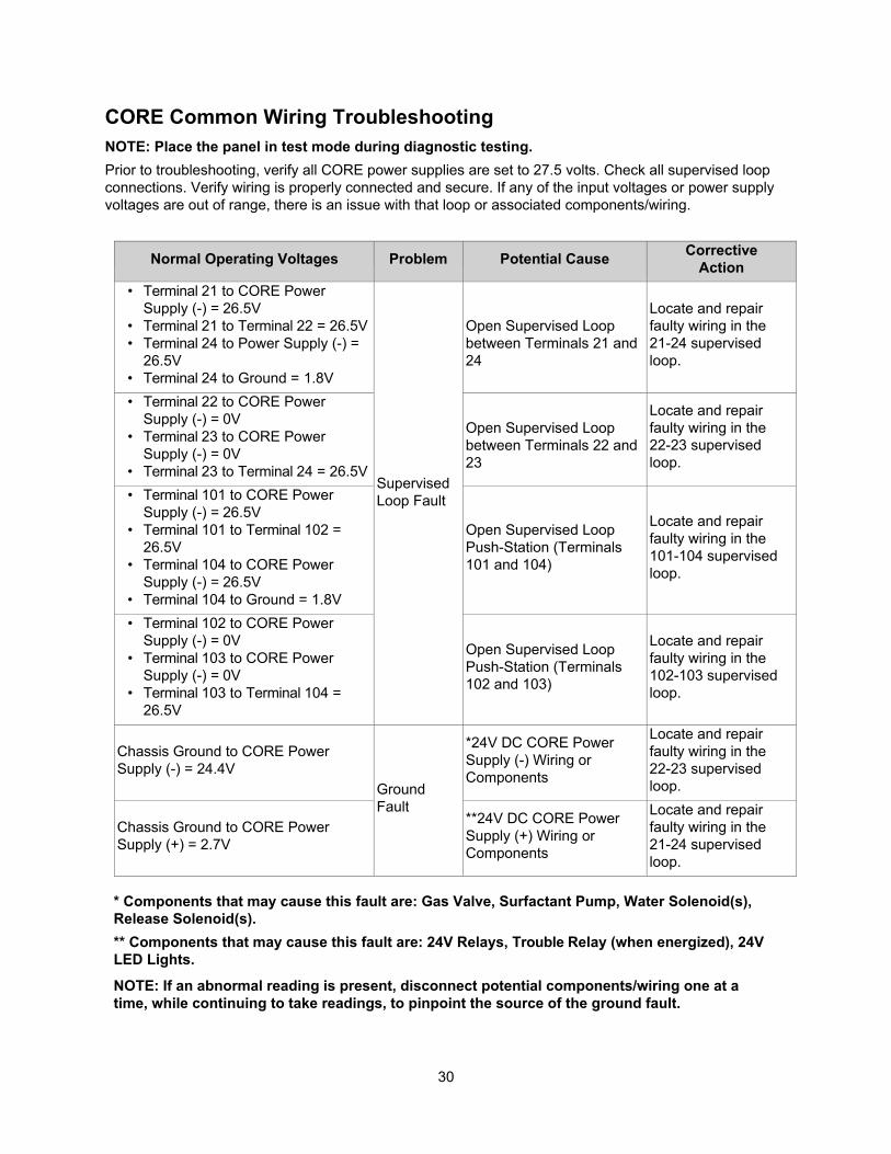
CORE Common Wiring Troubleshooting NOTE: Place the panel in test mode during diagnostic testing. Prior to troubleshooting, verify all CORE power supplies are set to 27.5 volts. Check all supervised loop connections. Verify wiring is properly connected and secure. If any of the input voltages or power supply voltages are out of range, there is an issue with that loop or associated components/wiring.
Normal Operating Voltages Problem Potential Cause Corrective Action
• Terminal 21 to CORE Power Supply (-) = 26.5V
• Terminal 21 to Terminal 22 = 26.5V • Terminal 24 to Power Supply (-) =
26.5V • Terminal 24 to Ground = 1.8V
Supervised Loop Fault
Open Supervised Loop between Terminals 21 and 24
Locate and repair faulty wiring in the 21-24 supervised loop.
• Terminal 22 to CORE Power Supply (-) = 0V
• Terminal 23 to CORE Power Supply (-) = 0V
• Terminal 23 to Terminal 24 = 26.5V
Open Supervised Loop between Terminals 22 and 23
Locate and repair faulty wiring in the 22-23 supervised loop.
• Terminal 101 to CORE Power Supply (-) = 26.5V
• Terminal 101 to Terminal 102 = 26.5V
• Terminal 104 to CORE Power Supply (-) = 26.5V
• Terminal 104 to Ground = 1.8V
Open Supervised Loop Push-Station (Terminals 101 and 104)
Locate and repair faulty wiring in the 101-104 supervised loop.
• Terminal 102 to CORE Power Supply (-) = 0V
• Terminal 103 to CORE Power Supply (-) = 0V
• Terminal 103 to Terminal 104 = 26.5V
Open Supervised Loop Push-Station (Terminals 102 and 103)
Locate and repair faulty wiring in the 102-103 supervised loop.
Chassis Ground to CORE Power Supply (-) = 24.4V
Ground Fault
*24V DC CORE Power Supply (-) Wiring or Components
Locate and repair faulty wiring in the 22-23 supervised loop.
Chassis Ground to CORE Power Supply (+) = 2.7V
**24V DC CORE Power Supply (+) Wiring or Components
Locate and repair faulty wiring in the 21-24 supervised loop.
* Components that may cause this fault are: Gas Valve, Surfactant Pump, Water Solenoid(s), Release Solenoid(s). ** Components that may cause this fault are: 24V Relays, Trouble Relay (when energized), 24V LED Lights.
NOTE: If an abnormal reading is present, disconnect potential components/wiring one at a time, while continuing to take readings, to pinpoint the source of the ground fault.
31
MAINTENANCE To guarantee trouble-free operation of this system, the manufacturer suggests following these guidelines. Most problems associated with unit failures are directly related to poor service and maintenance. Record any maintenance or service performed on this equipment in the documentation section located at the end of this manual.
General Maintenance 1. All water connections must be verified for tightness and leak-free operation. 2. The “Add Surfactant” indicating light will illuminate when the surfactant tank is empty. Surfactant
must be added immediately to guarantee proper fire system function.
Every 6 months 1. Inspect the surfactant pump for proper operation and ensure liquid-level sensor in surfactant tank
is operational. Test by manually lowering the sensor to see if the “Add Surfactant” light illuminates. 2. Fill surfactant tank with surfactant. Verify that the surfactant has not congealed or dried out, and
that the liquid level sensor operates correctly. 3. Verify that system has proper water pressure and temperature per the labels on the unit. 4. Inspect and Clean the CORE water supply strainer, upstream of all solenoid valves. 5. A certified technician should verify proper system activation via the supervised loop. Test and
inspect the fire system for CORE system. This includes verifying proper operation of the duct Firestat, all remote manual actuation devices (push/pull stations), proper surfactant injection and battery backup operation. Refer to the Start Up Procedure – CORE Protection Fire System on page 12 to check the proper operation of these components.
Every 2 Years 1. Replace batteries for the CORE Protection Systems. The replacement battery part number is PS-
1270-F2, two are required. Once the battery is disconnected, the connected equipment is not protected from power outages. The new battery must be installed immediately. Refer to the replacement battery installation guide for more details.
2. Inspect condition of all wires and plumbing. Plumbing should be free of corrosion and wire insulation must be in good condition.
Decommissioning If it should become necessary to disconnect the CORE system from AC power for an extended period of time (more than 2 days), the batteries should be disconnected to prevent them from being damaged due to complete discharge.
System Discharge 1. All filters in the Pollution Control Unit must be replaced. 2. Drain line and discharge line must be checked for proper drainage. If there is any water
accumulation in the lines, the lines could burst due to freezing. 3. Inspect and Clean CORE water supply line strainer, upstream of all solenoid valves. 4. Surfactant tank must be refilled. 5. All nozzle caps must be re-installed on the nozzles. This will prevent buildup of grease in the nozzle
opening.
32
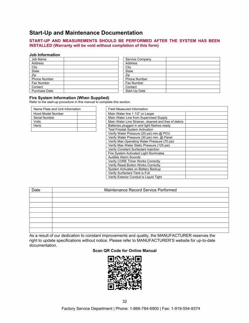
Start-Up and Maintenance Documentation START-UP AND MEASUREMENTS SHOULD BE PERFORMED AFTER THE SYSTEM HAS BEEN INSTALLED (Warranty will be void without completion of this form) Job Information
Job Name Service Company Address Address City City State State Zip Zip Phone Number Phone Number Fax Number Fax Number Contact Contact Purchase Date Start-Up Date
Fire System Information (When Supplied) Refer to the start-up procedure in this manual to complete this section.
Name Plate and Unit Information Field Measured Information Hood Model Number Main Water line 1 1/2” or Larger Serial Number Main Water Line from Supervised Supply Volts Main Water Line Strainer, cleaned and free of debris Hertz Batteries plugged in and light flashes ready Test Firestat System Activation Verify Water Pressure (20 psi) min.@ PCU Verify Water Pressure (30 psi) min. @ Panel Verify Max Operating Water Pressure (70 psi) Verify Max Water Static Pressure (125 psi) Verify Constant Surfactant Injection Fire System Activated Light Illuminates Audible Alarm Sounds Verify CORE Timer Works Correctly Verify Reset Button Works Correctly System Activates on Battery Backup Verify Surfactant Tank is Full Verify Exterior Conduit is Liquid Tight
Date Maintenance Record Service Performed
As a result of our dedication to constant improvements and quality, the MANUFACTURER reserves the right to update specifications without notice. Please refer to MANUFACTURER’S website for up-to-date documentation.
Scan QR Code for Online Manual
Factory Service Department | Phone: 1-866-784-6900 | Fax: 1-919-554-9374