Embed Size (px)
Citation preview

Modern Robotics Inc.
Core Spartan Controller Documentation
Version 3.0.3 August 2, 2017

Core Spartan Documentation Modern Robotics, Inc
Version 3.0.3 Page 2
Contents 1. Document Control ................................................................................................................. 4
2. Description ............................................................................................................................. 5
3. Express Installation via Ardublockly for Spartan ............................................................... 6
3.1. Installation of Ardublockly for Spartan (Windows Only) .................................. 6
4. Manual Installation of Core Spartan Resources .................................................................. 7
4.1. Installation of Library via .zip ............................................................................... 7
4.2. Installation of the Board via Arduino Board Manager ....................................... 9
4.3. Testing Installation of Library and Board ......................................................... 12
4.4. Using your Spartan .............................................................................................. 14
5. Modern Robotics Spartan Coding Methods ....................................................................... 15
5.1. Modern Robotics Header .................................................................................... 16
5.2. Include Statements .............................................................................................. 17
5.3. Object Declarations ............................................................................................. 17
5.4. Setup ..................................................................................................................... 18
5.5. Loop ...................................................................................................................... 19
5.6. Add your own functions ...................................................................................... 20
6. Core Spartan Controller (45-2000) ................................................................................... 21
6.1. Core Spartan Controller Information ................................................................. 22
6.2. Servos ................................................................................................................... 24
6.3. Motors ................................................................................................................... 26
6.4. Core Reset............................................................................................................. 28
6.5. Core LED ............................................................................................................... 28
6.6. I2C Address .......................................................................................................... 28
7. Serial Communication ......................................................................................................... 29
8. Three Wire Analog & Digital Sensors ................................................................................ 30
8.1. Program Control Button (45-2002) ................................................................... 31
8.2. Rate Gyro (45-2004) ........................................................................................... 33
8.3. Optical Distance Sensor (45-2006) .................................................................... 34
8.4. Touch Sensor (45-2007) ..................................................................................... 35
8.5. Light Sensor (45-2015) ....................................................................................... 36
8.6. Magnet Sensor (45-2020) ................................................................................... 37
9. Four Wire Digital I2C Sensors ............................................................................................ 38
9.1. I2C Class ............................................................................................................... 39

Core Spartan Documentation Modern Robotics, Inc
Version 3.0.3 Page 3
9.2. Compass (45-2003) ............................................................................................. 41
9.3. Integrating Gyro (45-2005) ................................................................................ 44
9.4. Range Sensor (45-2008) ..................................................................................... 47
9.5. IR Locator 360 (45-2009) ................................................................................... 49
9.6. Sound Generator (45-2016) ............................................................................... 51
9.7. IR Seeker V3 (45-2017)....................................................................................... 54
9.8. Color Sensor (45-2018)....................................................................................... 56
9.9. Color Beacon (45-2019) ...................................................................................... 61

Core Spartan Documentation Modern Robotics, Inc
Version 3.0.3 Page 4
1. Document Control
Revision History
Version Date Description By
1.0.0 12/7/15 Initial Document Modern Robotics
1.1.0 1/15/16 Added Diagrams/Explanations Modern Robotics
2.0.0 2/29/16 Reformat/Installation/Coding Methods Modern Robotics
2.1.0 5/17/16 Range-Locator-Compass/Minor fixes Modern Robotics
2.1.1 6/9/16 Update to reflect library change Modern Robotics
2.1.2 10/12/16 Minor text fixes Modern Robotics
2.2.0 2/6/17 Added sensor support and minor fixes Modern Robotics
2.2.1 2/7/17 Document changed to reflect coding fix Modern Robotics
3.0.0 4/7/17 Library Changes/Sensor Support Modern Robotics
3.0.1 5/24/17 Ardublockly Install Guide Modern Robotics
3.0.2 7/10/17 Minor text fixes Modern Robotics
3.0.3 8/2/17 Changes made to reflect library changes. Modern Robotics
© Modern Robotics. Inc 2016 This document is published by Modern Robotics, Inc. No part of this document may be copied, published in print or shared online or otherwise publically released without the express written consent of Modern Robotics, Inc. Specifications subject to change without notice. Modern Robotics, Inc 13335 SW 124th St Miami, FL 33186 Phone: (786)393-6886 Email: [email protected] Web: www.modernroboticsinc.com

Core Spartan Documentation Modern Robotics, Inc
Version 3.0.3 Page 5
2. Description
The following document is a guide for the use and implementation of the Core Spartan Controller and all Core Sensor functions. The Core Spartan Controller is the control center that runs user code and handles all the data produced by the Core Sensors.
The Core Spartan Controller is easy to connect, control, and program your robot with the use of the Arduino IDE. The Core Spartan Controller is designed to control Core Sensors, servos and motors, using a USB-A to USB Mini-B cable to interface with the computer. The Core Spartan Library must be installed on your computer to have access to all the available functions that are used in controlling the Core Spartan Controller and its sensors. The board’s primary use is with the Spartan Robot; however, it can be used as a standalone microcontroller. There are twelve digital ports, four analog ports and four I2C ports for use with external sensors. The Core Spartan Controller also supports DC motors and servos by providing two motor ports and four servo ports. The Core Spartan Controller can be powered by USB that will power the board and the Core sensors. The main power supply is a 6V 2200mAh NiMH rechargeable battery that can power the board, sensors, servos and motors. The Core Sensors are designed and optimized for use with the Core Spartan Controller. The sensors come in two different forms, Three-Wire and Four-Wire configurations. All Four-Wire sensors are I2C sensors and must connect to one of the I2C ports on the board. The Three-Wire sensors are split between analog and digital. The analog sensors return values from 0 to 255 where the digital sensors return either a 0 or a 1. All of the sensors have an initialization function, also known as a constructor, i.e. CORE_PCB(), which must be called at the beginning of your code in order to use the sensor. When using any sensor and its accompanying library, the pinMode() function should never be used as some sensors change or hold the mode as input/output at certain times to function correctly. All mode initializations are automatically done when the sensor constructor is called. The sensors are compatible with the 8mm grid on the Matrix Robotics and Spartan Robotics kits. For more information on the use and implementation of the Core Spartan Controller and Core Sensors please refer to the examples folder in Arduino File ► Examples ► CoreSpartanController or you can visit us at http://www.modernroboticsinc.com/Spartan.
Core Spartan Documentation Modern Robotics, Inc
Version 3.0.3 Page 6
3. Express Installation via Ardublockly for Spartan Ardublockly is a block coding environment that makes it easy for anyone at any age to program their very own robot. When Ardublockly is installed it comes with the Ardublockly programming environment, Arduino 1.6.8, Core Spartan Library and the Core Spartan Controller Board.
3.1. Installation of Ardublockly for Spartan (Windows Only)
Installing Ardublockly, Arduino and all required resources in one fell swoop. Step 1
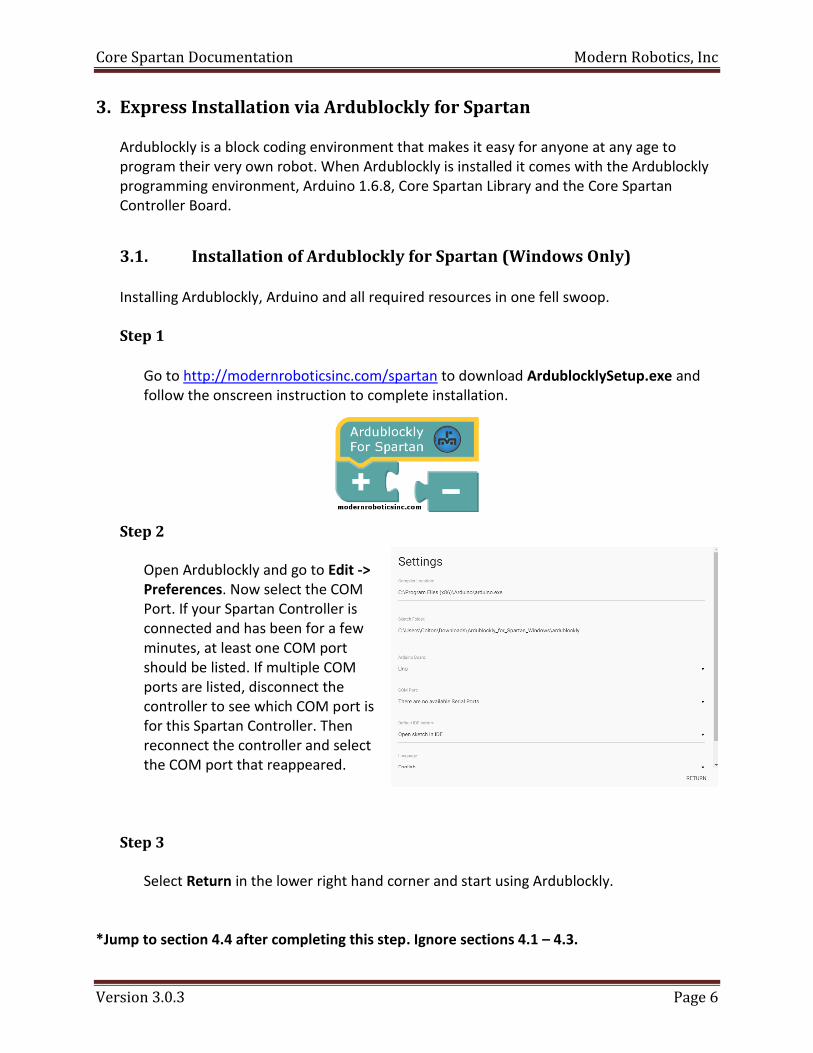
Go to http://modernroboticsinc.com/spartan to download ArdublocklySetup.exe and follow the onscreen instruction to complete installation.
Step 2
Open Ardublockly and go to Edit -> Preferences. Now select the COM Port. If your Spartan Controller is connected and has been for a few minutes, at least one COM port should be listed. If multiple COM ports are listed, disconnect the controller to see which COM port is for this Spartan Controller. Then reconnect the controller and select the COM port that reappeared.
Step 3
Select Return in the lower right hand corner and start using Ardublockly.
*Jump to section 4.4 after completing this step. Ignore sections 4.1 – 4.3.

Core Spartan Documentation Modern Robotics, Inc
Version 3.0.3 Page 7
4. Manual Installation of Core Spartan Resources The following is a guide to install the resources necessary to control a Core Spartan Controller on any platform that supports Arduino. There are two main steps involved in installation of Core Spartan Resources: installation of library and examples via a .zip file and installation of the board file via the Arduino Board Manager. If you encounter issues with any step of the installation process, please attempt closing and reopening the Arduino program or restarting your computer as these methods may fix any issues. If your problems persist, please contact Modern Robotic Support at [email protected].
4.1. Installation of Library via .zip
Installing the Core Spartan Controller Library via a .zip file is an easy and tested method of loading third party libraries into the Arduino IDE. The following steps will use Windows and Arduino 1.6.8 for installation. This method may also be used on Mac and Linux machines.
Step 1
Go to http://modernroboticsinc.com/spartan and download the CoreSpartanController.zip file.
Step 2
Open your Arduino IDE and navigate to Sketch ► Include Library ► Add .ZIP Library… Click on Add .ZIP Library

Core Spartan Documentation Modern Robotics, Inc
Version 3.0.3 Page 8
Step3
Navigate using the file browser to the place where CoreSpartanController.zip was downloaded. Then click “Open” to load the file into the Arduino IDE. Arduino will respond if the library was successfully installed or if it failed.
Step 4
Restart the Arduino IDE to ensure that Core Spartan Controller Library is fully loaded. To verify that your library is installed, please check to see if CoreSpartanController show up in the corresponding locations.
Core Spartan Documentation Modern Robotics, Inc
Version 3.0.3 Page 9
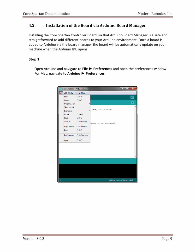
4.2. Installation of the Board via Arduino Board Manager
Installing the Core Spartan Controller Board via that Arduino Board Manager is a safe and straightforward to add different boards to your Arduino environment. Once a board is added to Arduino via the board manager the board will be automatically update on your machine when the Arduino IDE opens.
Step 1
Open Arduino and navigate to File ► Preferences and open the preferences window. For Mac, navigate to Arduino ► Preferences.

Core Spartan Documentation Modern Robotics, Inc
Version 3.0.3 Page 10
Step 2
In the lower half of the window there is a field labeled “Addition Boards Manager URLs.” This is where you want to paste the URL: http://modernroboticsinc.com/Content/Images/uploaded/Spartan/ArduinoLibrary/package_CORE_SUPPORT_index.json
Once you have completed this step, click “OK”.
Step 3
Now navigate to Tools ► Boards ► Boards Manager… and open the board manager.

Core Spartan Documentation Modern Robotics, Inc
Version 3.0.3 Page 11
Step 4
Type “Spartan” into the search bar to find the Core Spartan Controller. Find the Modern Robotics AVR Boards that has the Core Spartan Controller package and install it by click the “Install” button in the lower right corner of the box.
Step 5
Select the Core Spartan Controller as the board you want to use by navigating to Tools ► Boards ► Core Spartan Controller. This board must be selected to ensure the Core Spartan Controller and all of the MR Sensors work properly.

Core Spartan Documentation Modern Robotics, Inc
Version 3.0.3 Page 12
4.3. Testing Installation of Library and Board
To test and verify the installation of all the components please restart the Arduino IDE. Step 1
Go to File(Arduino) ► Examples ► CoreSpartanController ► CoreController ► FlashLEDs and upload the program to the Core Spartan Controller.
Step 2
Connect your Core Spartan Controller to your computer. If this is your first time connecting the controller to your computer, you may have to wait for drivers to install on your computer before you can continue. The Battery does not need to be connected for this program to run. The Red and Blue LEDs on the Core Spartan Controller should be blinking with a 500mS on/off cycle when first connected to power or a computer.

Core Spartan Documentation Modern Robotics, Inc
Version 3.0.3 Page 13
Step 3
Go to Tools ► Ports ► Core Spartan Controller to set the port to the Core Spartan Controller. If your Core Spartan Controller does no show in the list of COM ports (/dev/cu.usbserial- for Mac) then your module has not yet fully installed drivers on your computer.
Step 4
Upload the FlashLEDs.ino program to your Core Spartan Controller. Click the “Upload” button which is the second button in from the left side that looks like a circle with an arrow pointing to the right. Then wait for the upload process to complete and the words, “Done uploading” to appear in the lower blue bar(as seen below).

Core Spartan Documentation Modern Robotics, Inc
Version 3.0.3 Page 14
Step 5
If you have successfully compiled and uploaded the program to your Core Spartan Controller you will notice the Red and Blue on board LEDs are blinking with a 50mS on/off cycle. When the Core Spartan Controller is first connected the Red and Blue LEDs will blink back and forth at a slow pace. If you have successfully compiled and uploaded the program to your Core Spartan Controller, the LEDs will blink at a much faster rate (50ms intervals).
4.4. Using your Spartan
There will be times when you want to leave your Core Spartan Controller connected to your computer to use the serial monitor for debugging programs. There will also be time where you will want to run your robot free of anything tethering the robot to one location (USB cable). When using the Spartan Robot free of connections, you will first want to verify that a program was successfully uploaded to your Core Spartan Controller before disconnecting from the computer. Once your program is uploaded and disconnected from the computer you will need to turn the power switch located on the left side of the Core Spartan Controller to the ON position. The Spartan Robot will now be running on battery power and when powered on, run your code. Hitting the RESET button on the Core Spartan Controller will reset your code and variables as well as start the program from the beginning. Refer to section 5 of this document for further information on the Core Spartan Controller.

Core Spartan Documentation Modern Robotics, Inc
Version 3.0.3 Page 15
5. Modern Robotics Spartan Coding Methods
This section will break down the style of coding used in the examples and explain some syntax used in the code. For questions or concerns about the programming language, please contact us at [email protected] for assistance.
Modern Robotics Header
Include Statements
Object Declarations
Setup
Loop
Add your own functions

Core Spartan Documentation Modern Robotics, Inc
Version 3.0.3 Page 16
5.1. Modern Robotics Header
The Modern Robotics Header is in every example published by Modern Robotics. At the top of the header is the name of the file and the main sensors that are being used in the program. Below that are two to three paragraphs are designed to be informative by explaining the sensor use and a description of the expected behavior of the example. Should an example not perform the way it is described in the example check that your wiring matches the “Connections” section of the header. Next is a list of connections to the Core Spartan Controller. In more complex examples the list of connections contains more sensors, motors and servos. Connections: Left Optical Distance sensor (ODS) = Port A0 Right Optical Distance sensor (ODS) = Port A1 Program Control Button (PCB) = Port D2 Touch Sensor = Port D7 Left Motor = Motor Port M1 (- +) Right Motor = Motor Port M0 (+ -) At the bottom of the header is a statement that is found across all the examples. The first half notes not to use pinMode()when using a Modern Robotics Sensor because the pinMode() is being handled within the library. The second half of the statement states where to find more language references and keyboard shortcuts to opening the serial monitor. “NOTE* When using any Core sensor and its accompanying library, the pinMode() function should never be used as some sensors change or hold the mode as input/output at certain times to function correctly. All mode initializations are automatically done when the sensor constructor is called. i.e. CORE_PCB(). IMPORTANT: PCB.delayedStart(); must be the first line in setup() when PCB is being used as a start/stop button. Core Spartan language reference can be found at http://modernroboticsinc.com/spartan Arduino language reference can be found at http://arduino.cc/en/Reference/HomePage Windows: USE SERIAL MONITOR -> Ctrl+Shift+M Mac: USE SERIAL MONITOR -> Cmd+Shift+M”

Core Spartan Documentation Modern Robotics, Inc
Version 3.0.3 Page 17
5.2. Include Statements
The include statement is a key function used to import other pieces of code into the current file. For our use we include the CORE.h header file which includes all basic Core Spartan Controller functions and sensor libraries. When including CORE.h into your code double quotes (“”) must be used and not the angled brackets (<>).
#include “CORE.h”
5.3. Object Declarations
The Object Declaration is a key step to using any of the Modern Robotics hardware. An object is an instance of a class which contains the blueprints for how a piece of code will work. When declaring an object, there are three main parts: the constructor, the name and the parameters.
Constructor name(parameter);
The Constructor is a special function in a class that is called to create an object. Below is a list of constructors that will be used with the Core Spartan Controller. CORE_SPARTAN CORE_INT_GYRO CORE_SEEKERV3 CORE_PCB CORE_RANGE CORE_COLOR_SENSOR CORE_DIGITAL CORE_COMPASS CORE_COLOR_BEACON CORE_ANALOG CORE_LOCATOR CORE_I2C CORE_SOUND
The name of the object declaration is completely arbitrary and very important. The name is used later in code when a function is being used from the class that the object was created. Below is an example of using the name to call motor functions. More detail on motor functions can be found later in this document (section 5.3).
CORE_SPARTAN myname; … myname.motorMode(myname.M0, myname.BRAKE); myname.motorSpeed(myname.M0, 50);
In this example motorMode and motorSpeed are class functions. Both M0 and BRAKE are class constants. They all must have the name “myname.” before and function or variable from the class can be used.

Core Spartan Documentation Modern Robotics, Inc
Version 3.0.3 Page 18
The naming of objects become crucial when using multiples of the same object. The example below demonstrates the use of naming multiple objects for use in code. The example will use the ODS sensor (section 7.3).
CORE_ANALOG left(A0); CORE_ANALOG right(A1); … left_value = left.read(); right_value = right.read();
In this example both the left and right optical distance sensors use the same function read(). It is because of the name (left or right) that determines which object the read function is being read from. The parameter is the content inside the parenthesis. When used in the object declaration the parameter is used for identifying the location of a sensor. For all 3 wire sensors, the parameter refers to the port where the sensor is connected. For all 4 wire sensors, the parameter is the I2C address of that sensor. However, if you are using a sensor with a default address, (i.e. you have not modified the I2C address of the sensor) then you may omit the parameter field. There is more information about I2C and I2C sensors in the 4 wire section of this document.
5.4. Setup
The setup of the code is run through once and only once. Therefore, the setup is the perfect place to initialize values and set up your code. In most MRI examples the setup includes PCB.delayedStart() and Serial.begin(9600) as seen below.
int value; void setup(){ PCB.delayedStart(); Serial.begin(9600); value = 0; }
The first to appear is PCB.delayedStart(). This line is using the program control button as a start/reset button for the entire program. For delayedStart to work the PCB must be connected to port D2. The next common line to show up in an example is Serial.begin(9600). This line starts the serial bus so that we may print text and returned values to the serial monitor. Using serial prints is a big help in debugging any code.

Core Spartan Documentation Modern Robotics, Inc
Version 3.0.3 Page 19
5.5. Loop
The loop is the part in code that follows directly after the setup. The loop consecutively loops around allowing the program to continually run. The below example assumes “CORE_DIGITAL touch(7);” is called before setup.
void loop(){ if(touch.read() == 0) Serial.println(“value is 0”); if(touch.read() == 1) Serial.println(“value is 1”); }
If you don’t want have your code loop continuously you can add a while 1 loop at the very last line in the loop.
void loop(){ if(touch.read() == 0) Serial.println(“value is 0”); if(touch.read() == 1) Serial.println(“value is 1”); while(1); }

Core Spartan Documentation Modern Robotics, Inc
Version 3.0.3 Page 20
5.6. Add your own functions
Using a user function can really help clean up code or help in using complex algorithms. All user functions must be declared after the loop and can be any type (void, int, char, etc). For example, in the example GetInfo.ino there is a custom function placed after the loop.
void cls (void){ int counter = 100; while(counter--) Serial.print("\n"); }
This function is called inside the loop making user functions clean and easier to dissect. This will be helpful later for debugging or improvement of the program.
void loop(){ cls(); …. more code …. }
Without making the user function the loop would contain the code that was inside the function resulting in the loop looking like the following.
void loop(){ int counter = 100; while(counter--) Serial.print("\n"); …. more code …. }
Please refer to the GetInfo.ino example for more information. In the example you can copy the contents of the user function and place it where the cls() function is called and run it to demonstrate that it can work either way.

Core Spartan Documentation Modern Robotics, Inc
Version 3.0.3 Page 21
6. Core Spartan Controller (45-2000)
The Core Spartan Controller is the processing and control center for the all the Core sensors. Core is driven by an Atmega328P chip using the Optiboot bootloader that controls all the Core sensors. A PIC24F Microchip is used to drive the motors and servos using a PWM signal. The chips communicate with each other via I2C communication. Battery power must be ON to use the Core functions, i.e. motors, servos and information. The reset button is a hardware reset that restarts the on-board chips and starts the program from start. Refer to the Core example folder for more information on different implementation methods.
http://modernroboticsinc.com/core-spartan-controller - 12 Digital Ports - 2 Digital LEDs on D12 and D13 - 4 Analog Ports - 4 I2C Ports (1 I2C Bus) - 4 Servo Ports - 2 DC Motor Ports - 1 Battery Port - 1 Battery Charger Port - 1 Reset Button - 1 Battery Power Switch
To charge your battery, connect the battery and the charger to the Core Spartan Controller where indicated and leave connected until the charger light turns green. The Spartan charger can be connected in either direction but the battery must follow the correct polarity.
Battery Charger

Core Spartan Documentation Modern Robotics, Inc
Version 3.0.3 Page 22
*** When compiling, use the Core Spartan Controller, in the Tools ► Board ► Core Spartan Controller *** Core Functions: CORE_SPARTAN(); long getInfo(void); unsigned char getControllerStatus(void) unsigned char getBatteryVoltage(void) void servoEnable(unsigned char servo, unsigned char enable) void servoTarget(unsigned char servo, unsigned char target) int servoPosition(unsigned char servo) void motorMode(unsigned char motor, unsigned char mode) void motorSpeed(unsigned char motor, int speed) void reset(void) void led(unsigned char led, unsigned char state)
6.1. Core Spartan Controller Information CORE_SPARTAN(void)
This constructor creates an instance of the Core class which will allow for all basic motor, servo and information functions. CORE_SPARTAN CORE;
long getInfo(void)
Returns the version number, manufacturing number and ID number to the user. long info, version, manuf, id; info = CORE.getInfo(); version = info & 0x000000FF; manuf = (info & 0x0000FF00) >> 8; id = (info & 0x00FF0000) >> 16;

Core Spartan Documentation Modern Robotics, Inc
Version 3.0.3 Page 23
unsigned char getControllerStatus(void)
Returns the status of the battery to the user. 0 – Normal Operation 1 – Battery Fault 2 – Battery Low
unsigned char value; value = CORE.getControllerStatus(); …or… Serial.print(CORE.getControllerStatus());
unsigned char getBatteryVoltage(void)
Returns the current battery voltage in 40mV increments to the user. If value=35, then battery voltage is (35 x 0.04) = 1.4V
unsigned char value; value = CORE.getBatteryVoltage(); …or… Serial.print(CORE.getBatteryVoltage());

Core Spartan Documentation Modern Robotics, Inc
Version 3.0.3 Page 24
6.2. Servos Servos come with a variety of colored wire. Please ensure that your servo follows this wiring scheme before operation.
PWM +5V Ground

Core Spartan Documentation Modern Robotics, Inc
Version 3.0.3 Page 25
void servoEnable(unsigned char servo, unsigned char enable) This function turns the servo(s) on or off. This function may be called anywhere in code, however it is advised to use it in the setup function. The parameter servo refers to which servo will be enabled or disabled. The parameter enable determines if the servo(s) will be on or off.
Constants Definition
ON Turns selected servo on
OFF Turns selected servo off
S0 Reference to Servo 0
S1 Reference to Servo 1
S2 Reference to Servo 2
S3 Reference to Servo 3
CORE.servoEnable(CORE.S0, CORE.OFF); …or… CORE.servoEnable(CORE.S1+ CORE.S2, CORE.ON);
void servoTarget(unsigned char servo, unsigned char target)
This function moves the servo(s) to a specified target location. The parameter servo refers to which servo will change position. The parameter’s target takes a number between 0 and 255 that will change the position of the servo. However, when operating at <50 or >205, listen to the servo and ensure that it is not continually trying to go beyond its internal mechanical limit. This may cause damage to the servo and waste battery power.
CORE.servoTarget(CORE.S0, 120); …or… CORE.servoTarget(CORE.S1+ CORE.S2+ CORE.S3, 200);
int servoPosition(unsigned char servo)
This function returns the last known position of the servo. If a servo is moved manually the value will not be consistent with the servo position. int value; value = CORE.servoPosition(CORE.S3); …or… Serial.print(CORE.servoPosition(CORE.S1));

Core Spartan Documentation Modern Robotics, Inc
Version 3.0.3 Page 26
6.3. Motors
OR
The Core Spartan Controller works with the Spartan DC Motors. The Spartan DC Motors are housed in a servo style housing with two wires: red for power and black for ground. Connecting the motors in reverse polarity will switch the direction of motor rotation and will not cause any damage to the controller or the motors.

Core Spartan Documentation Modern Robotics, Inc
Version 3.0.3 Page 27
void motorMode(unsigned char motor, unsigned char mode) This function sets the mode for the motor(s). The parameter motor refers to the motor(s) that will experience the change in state. The parameter mode refers to the way the motor(s) will function. In FLOAT mode, the motor is able to coast to a stop at a speed value of 0, unlocking the motor allowing it to spin freely. In BRAKE mode, the motor is halted at a speed value of 0, locking the motor to that position.
Constants Definition
FLOAT Coasts to stop on speed value of 0 (unlocked)
BRAKE Halted on speed value of 0 (locked)
M0 Reference to Motor 0
M1 Reference to Motor 1
CORE.motorMode(CORE.M0, CORE.FLOAT); …or… CORE.motorMode(CORE.M0+ CORE.M1, CORE.BRAKE);
void motorSpeed(unsigned char motor, int speed)
This function sets the speed for the motor(s). The parameter motors refers to the motor that will experience the change in state. The parameter speed is an integer value that ranges from -100 to 100 with 0 being motor stop. The sign of speed determines the motor direction. Since Core Spartan Controller is using DC motors, the DC motor connectors to the Core Spartan Controller can be flipped around to reverse motor direction, allowing the user to maintain sign convention. With both motors connect to Core Spartan Controller with the same polarity, moving in forward direction:
CORE.motorSpeed(CORE.M0,100); CORE.motorSpeed(CORE.M1,-100);
With one motor connection flipped, moving in forward direction:
CORE.motorSpeed(CORE.M0+ CORE.M1,100); …or… CORE.motorSpeed(CORE.M0+ CORE.M1,-100);
Core Spartan Documentation Modern Robotics, Inc
Version 3.0.3 Page 28
6.4. Core Reset void reset(void)
When this function is called, the Core Spartan Controller will reset like the hardware reset button. CORE. reset();
6.5. Core LED void led(unsigned char led, unsigned char state)
This function turns on and off the on-board LEDs. These LEDs correspond to digital ports 12 and 13, BLUE and RED respectively. CORE. led(CORE.RED_LED, CORE.ON); CORE. led(CORE.BLUE_LED, CORE.ON);
6.6. I2C Address void getI2C(void)
This function will print all connected I2C addresses to the serial monitor. The Serial.begin(9600); must be called in the setup for this function to print its contents. CORE.getI2C();
void changeI2C(int old_address, int new_address)
This function is used to change the I2C address for a sensor. This would allow for multiple of the same I2C sensor to be used at the same time. The range of acceptable I2C addresses is from 0x0B – 0x77. Refer to example changeI2c.ino for implementation of getI2C and changeI2C. The changeI2C function works only for Modern Robotics Sensors. CORE.changeI2C(0x3C, 0x4E);

Core Spartan Documentation Modern Robotics, Inc
Version 3.0.3 Page 29
7. Serial Communication The Spartan Controller supports serial communication on ports D0 (RX) and D1 (TX) and they are used to communicate with other devices or to the computer via USB. The code below is a method used to communicate between two Core Spartan Controllers. Please refer to https://www.arduino.cc/en/Reference/Serial for more information and examples about the Arduino Serial Library. Ports D0 and D1 should not have anything connected to them while uploading code to the board as it can interfere with serial communications.
void setup(){ Serial.begin(9600); } void loop(){ for(int data=0; data<10; data++){ Serial.write(data); } while(Serial.available() != 0){ int val = Serial.read(); Serial.println(val); } }
void setup(){ Serial.begin(9600); } void loop(){ while(Serial.available() != 0){ int val = Serial.read(); Serial.println(val); } for(int data=0; data<10; data++){ Serial.write(data); } }

Core Spartan Documentation Modern Robotics, Inc
Version 3.0.3 Page 30
8. Three Wire Analog & Digital Sensors All three wire sensors connect to either a digital port or an analog port. Therefore, if it is a digital sensor it returns a value of either 0 or 1. If the sensor is analog it returns a value between 0 and 255. The sensors consist of a black, red and yellow wire. The black wire is the ground wire and must line up with the black bar on the right side of the port. The red wire is the power wire that connects to 5V for all the sensors to operate on. The yellow wire is the variable voltage line that ranges from 0V-5V and it is used to send or receive signal. These sensors can be connected on the Core Spartan Controller using ports (D0 – D11) or (A0 – A3) depending on if the sensor is digital or analog. Ports D0 and D1, Rx and Tx respectively, should not have anything connected to them while uploading code to the board as it can interfere with serial communications. Each sensor of this type uses either the digital or analog class both with the ability to read and write. The constructor for the class must be called at the beginning of user code. The constructors name is arbitrary and a constructor must be called for each sensor being used. Refer to example programs for more information on sensor usage.
I/O +5V Ground
The Core Spartan Library includes wrapper classes for the default analog and digital functions. Analog Functions: CORE_ANALOG(char port) int read(void) void write(int) Digital Functions: CORE_DIGITAL(char port) int read(void) void write(int) Example:
CORE_ANALOG my_analog(A3); CORE_DIGITAL my_digital(5); value = my_analog.read(); my_digital.write(1);

Core Spartan Documentation Modern Robotics, Inc
Version 3.0.3 Page 31
8.1. Program Control Button (45-2002)
The Program Control Button (PCB) is intended for use in starting and stopping programs giving the user more control over their program. The sensor consists of a button and an LED that interact digitally with Core Spartan Controller. The PCB can be used with delayedStart() to reset and start the Core Spartan Controller, or with read() and writeLED() independent of the delayedStart() function. Refer to the Program Control Button example folder for more information on different implementation methods.
http://modernroboticsinc.com/program-control-button
Program Control Button functions: CORE_PCB(char input) int delayedStart(void) char read(void) void writeLED(uint8_t value)
CORE_PCB(char input)
This function is the constructor; it turns the CORE_PCB class into an object. The parameter input is a byte that corresponds to the port that the button is connected to. CORE_PCB PCB(3); …or… CORE_PCB;

Core Spartan Documentation Modern Robotics, Inc
Version 3.0.3 Page 32
int delayedStart(void)
If delayedStart() is called and the button is not connect to D2, the function returns -1, otherwise it returns 0. When the delayedStart() function is called, Core Spartan Controller will wait inside that function until the PCB is pressed. At this point the button acts as a start button and the LED will be blinking. Once the button is pushed the program will start the next line of code after the delayedStart() call. The LED is now off and the button acts as an immediate stop and reset button. When the button is triggered The Core Spartan Controller will reset the onboard chips and the program returns to the delayedStart() function after resetting the board. This function is all that is needed to make the PCB work as the program control button. PCB.delayedStart();
* delayedStart() must be called first in the setup before any initializations*
char read(void)
This allows the user to read the current state of the button by returning a character to the user. DO NOT change the I/O status of the port. The button can be used on any digital port as long as delayedStart() is not being used on that sensor. unsigned char value; … value = PCB.read(); …or… Serial.print(PCB.read());
void writeLED(int value)
This allows the user to easily write to the LED on the PCB sensor. The variable value takes the type of an integer and it is either a 0 or a 1. DO NOT change the I/O status of the port. The button can be used on any digital port as long as delayedStart() is not being used. PCB.writeLED(OFF); …or… PCB.writeLED(ON);

Core Spartan Documentation Modern Robotics, Inc
Version 3.0.3 Page 33
8.2. Rate Gyro (45-2004)
The Rate Gyro is used to detect the rate of rotation. When the Rate Gyro is completely still, the returned reading is 1.4V which produces a reading of 280° ±2°. With the sensor idle at 280° a Counter Clockwise (CCW) rotation will increase the value of the reading and then return to 280° once movement is stopped. A Clockwise (CW) rotation of the gyro will cause a decrease in the return value and return to 280° once the sensor is no longer moving. The readings are accurate to the degree. Refer to the Rate Gyro example folder for more information on different implementation methods.
Rate Gyro functions:
CORE_ANALOG(unsigned char port) int read(void) CORE_ANALOG(unsigned char port)
Save the pinMode for future reads and writes. This must be done before setup().
CORE_ANALOG GYRO(A2);
int read(void) Returns the value read by the gyro.
int value; value = GYRO.read(); …or… Serial.print(GYRO.read());
Core Spartan Documentation Modern Robotics, Inc
Version 3.0.3 Page 34
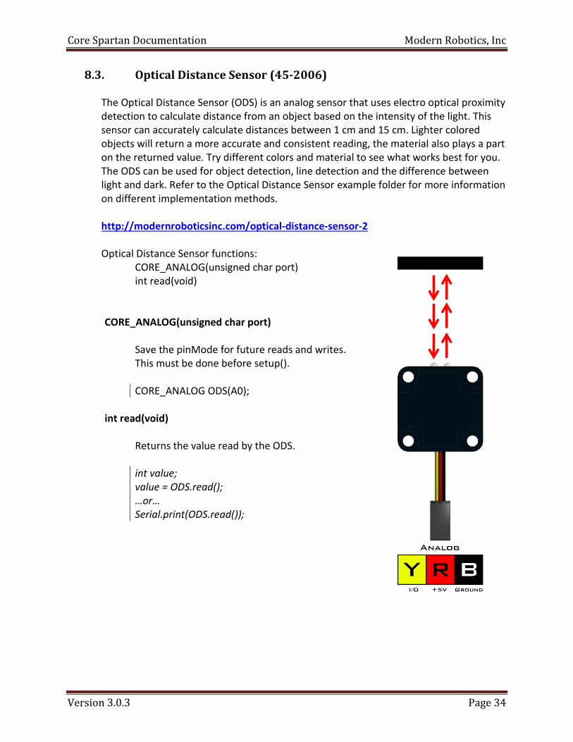
8.3. Optical Distance Sensor (45-2006) The Optical Distance Sensor (ODS) is an analog sensor that uses electro optical proximity detection to calculate distance from an object based on the intensity of the light. This sensor can accurately calculate distances between 1 cm and 15 cm. Lighter colored objects will return a more accurate and consistent reading, the material also plays a part on the returned value. Try different colors and material to see what works best for you. The ODS can be used for object detection, line detection and the difference between light and dark. Refer to the Optical Distance Sensor example folder for more information on different implementation methods. http://modernroboticsinc.com/optical-distance-sensor-2
Optical Distance Sensor functions: CORE_ANALOG(unsigned char port) int read(void)
CORE_ANALOG(unsigned char port)
Save the pinMode for future reads and writes. This must be done before setup().
CORE_ANALOG ODS(A0);
int read(void)
Returns the value read by the ODS.
int value; value = ODS.read(); …or… Serial.print(ODS.read());

Core Spartan Documentation Modern Robotics, Inc
Version 3.0.3 Page 35
8.4. Touch Sensor (45-2007) The Touch Sensor can be used for an array of different tasks including object detection, counter, standard push button and many more. The sensor returns either a 0 or a 1. The Touch Sensor can be attached to either the analog or digital ports. Refer to the Touch Sensor example folder for more information on different implementation methods. http://modernroboticsinc.com/touch-sensor-2
Touch Sensor functions: CORE_DIGITAL(unsigned char port) int read(void)
CORE_DIGITAL(unsigned char port)
Save the pinMode for future reads and writes. This must be done before setup(). CORE_DIGITAL button(7);
int read(void) Returns the value read by the TOUCH as either
a 0 or 1.
int value; value = button.read(); …or… Serial.print(button.read());

Core Spartan Documentation Modern Robotics, Inc
Version 3.0.3 Page 36
8.5. Light Sensor (45-2015)
The Light Sensor detects the ambient light level using a phototransistor. It returns a quasi-logarithmic analog value that allows the Light Sensor to be used over at least four decades of light. This means that the Light Sensor can detect small changes in light and dark environments. Refer to the Light Sensor example folder for more information on different implementation methods.
Light Sensor functions:
CORE_ANALOG(unsigned char port) int read(void) CORE_ANALOG(unsigned char port)
Save the pinMode for future reads and writes. This must be done before setup().
CORE_ANALOG light(A3);
int read(void) Returns the value read by the Light Sensor.
int value; value = light.read(); …or… Serial.print(light.read());
Core Spartan Documentation Modern Robotics, Inc
Version 3.0.3 Page 37
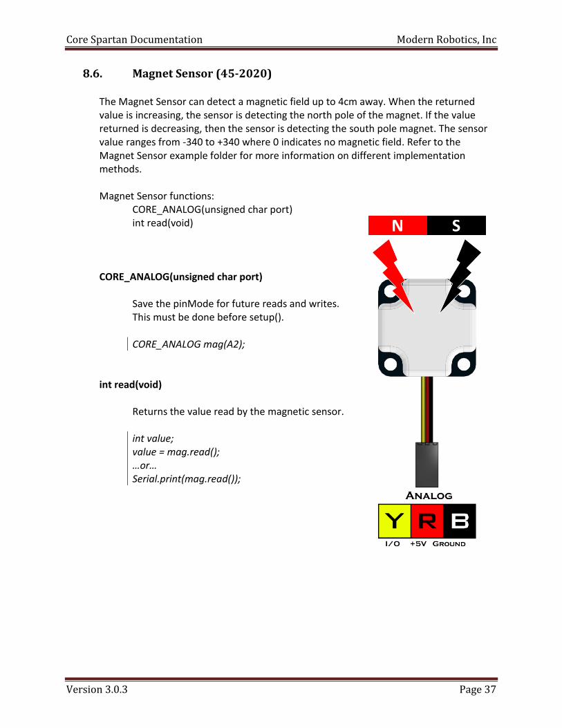
8.6. Magnet Sensor (45-2020)
The Magnet Sensor can detect a magnetic field up to 4cm away. When the returned value is increasing, the sensor is detecting the north pole of the magnet. If the value returned is decreasing, then the sensor is detecting the south pole magnet. The sensor value ranges from -340 to +340 where 0 indicates no magnetic field. Refer to the Magnet Sensor example folder for more information on different implementation methods.
Magnet Sensor functions:
CORE_ANALOG(unsigned char port) int read(void) CORE_ANALOG(unsigned char port)
Save the pinMode for future reads and writes. This must be done before setup().
CORE_ANALOG mag(A2);
int read(void) Returns the value read by the magnetic sensor.
int value; value = mag.read(); …or… Serial.print(mag.read());
Core Spartan Documentation Modern Robotics, Inc
Version 3.0.3 Page 38
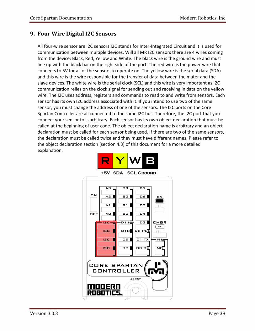
9. Four Wire Digital I2C Sensors
All four-wire sensor are I2C sensors.I2C stands for Inter-Integrated Circuit and it is used for communication between multiple devices. Will all MR I2C sensors there are 4 wires coming from the device: Black, Red, Yellow and White. The black wire is the ground wire and must line up with the black bar on the right side of the port. The red wire is the power wire that connects to 5V for all of the sensors to operate on. The yellow wire is the serial data (SDA) and this wire is the wire responsible for the transfer of data between the mater and the slave devices. The white wire is the serial clock (SCL) and this wire is very important as I2C communication relies on the clock signal for sending out and receiving in data on the yellow wire. The I2C uses address, registers and commands to read to and write from sensors. Each sensor has its own I2C address associated with it. If you intend to use two of the same sensor, you must change the address of one of the sensors. The I2C ports on the Core Spartan Controller are all connected to the same I2C bus. Therefore, the I2C port that you connect your sensor to is arbitrary. Each sensor has its own object declaration that must be called at the beginning of user code. The object declaration name is arbitrary and an object declaration must be called for each sensor being used. If there are two of the same sensors, the declaration must be called twice and they must have different names. Please refer to the object declaration section (section 4.3) of this document for a more detailed explanation.
+5V SDA SCL Ground

Core Spartan Documentation Modern Robotics, Inc
Version 3.0.3 Page 39
9.1. I2C Class
The I2C class was design to make generic I2C reads and writes easier to use. I2C class makes use of the Wire library provided by Arduino.
I2C Functions: CORE_I2C(int address) void request(int location, int length) unsigned char read(void) int available(void) void write(int location, unsigned char data) void write(int location, unsigned char data[], int length) CORE_I2C(int address)
Save the I2C address for future reads and writes. This must be done before setup(). CORE_I2C sensor; …or… CORE_I2C sensor(0x12);
void request(int location, int length)
Request any number of bytes (up to 16 bytes) to be read from an I2C sensor. The parameter location is the starting register location and length is the number of bytes to return. When request is called the values are read and stored into a buffer that can be accessed using the read() function. sensor.request(0x04, 2); …or… sensor.request(0x00, 4);
unsigned char read(void)
Returns the next available byte in the I2C read buffer that was created from the request() function. This function must be called each time value = sensor.read(); …or… Serial.println(sensor.read());

Core Spartan Documentation Modern Robotics, Inc
Version 3.0.3 Page 40
int available(void)
Checks to see if there is any data left in the buffers from a previous request. while(sensor.available()) value = sensor.read(); …or… if(sensor.available != 0) value = sensor.read();
void write(int location, unsigned char data)
Complete a signal byte write to a selected register location. The parameter location refers to the location in which the data is to be written. The parameter data is the size of one byte which allows data to be 0x00 – 0xFF (0 – 255). sensor.write(0x03, 0x43); …or… sensor.write(0x04, 175);
void write(int location, unsigned char data[], int length)
Complete a multiple byte write to concurrent registers. The parameter location refers to the location in which the data is to be written. The parameter data[] is an array of bytes which allows each piece of data to be 0x00 – 0xFF (0 – 255). Length if the number of bytes being written to the I2C sensor. The location is 0x03 and the length is 4, then register 0x03, 0x04, 0x05 and 0x06 will be written to. sensor.write(0x03, data, 4); …or… sensor.write(0x04, {3, 0x43, 7}, 3);

Core Spartan Documentation Modern Robotics, Inc
Version 3.0.3 Page 41
9.2. Compass (45-2003)
The Compass uses a magnetometer and an accelerometer to calculate heading data based on Earth’s magnetic field. The compass can return the heading data, accelerometer data and magnetometer data to the user. Anything that generates a magnetic field must be moved away from the sensor like power cables, motor or magnetic material. This must happen because during calibration the sensor will add an offset to account for other magnetic sources in the area. Make sure the sensor is pointing as close to due north as possible during the calibration. Refer to the Compass example folder for more information on different implementation methods. http://modernroboticsinc.com/compass-acceleration-tilt-sensor Default I2C Address= 0x24 Arduino I2C Address = 0x12 Compass Functions: CORE_COMPASS(int address) void hardIronCalibration(void) int getHeading(void) void nullAccelerometer(char axis) int getAccelerometer(char axis) void tiltUp(void) void tiltDown(void) int getMagnetometer(char axis) float scaleAccelometer ()
CORE_COMPASS(int address)
Save the I2C address for future reads and writes. This must be done before setup(). CORE_COMPASS COMP; …or… CORE_COMPASS COMP(0x12);

Core Spartan Documentation Modern Robotics, Inc
Version 3.0.3 Page 42
void hardIronCalibration(void)
Hard Iron Calibration (HIC) is a method of checking for magnets or an object generating a magnetic field around the sensor and generating an offset to account for the magnetic field. During HIC the sensor must be rotated 360° in 5 seconds while keeping a constant pace. Try to start and stop the sensor pointing due north. Refer to CalibrationHardIron example program for full calibration details. COMP.hardIronCalibration();
int getHeading(void)
This function returns the heading that ranges between 0 and 359. The heading is calculated from the accelerometer readings, the magnetometer readings, and the data collected during calibration.
int value; value = COMP.getHeading(); …or… Serial.print(COMP.getHeading());
void nullAccelometer(char axis)
This function will calibrate the X, Y and Z values by zeroing them. The X and Y calibration must be done with the sensor laying flat on the horizon. The Z must be calibrated with the sensor held vertical. Allow a minimum of 3 seconds for calibration. COMP.nullAccelerometer(X); COMP.nullAccelerometer (Y); COMP.nullAccelerometer (Z);
int getAccelerometer(char axis)
This function returns the accelerometer values for the X, Y and Z axis.
int value; value = COMP.getAccelerometer (); …or… Serial.print(COMP.getAccelerometer ());

Core Spartan Documentation Modern Robotics, Inc
Version 3.0.3 Page 43
void tiltUp(void)
This function calculates an offset to compensate for the magnetic field not being perfectly horizontal. The sensor must be held 20° above the horizon during calibration. COMP.tiltUp
void tiltDown(void)
This function calculates an offset to compensate for the magnetic field not being perfectly horizontal. The sensor must be held 20° below the horizon during calibration. COMP.tiltDown();
int getMagnetometer(char axis);
This function returns the values of the magnetometer on the X, Y and Z axis.
int value; value = COMP.getMagnetometer(); …or… Serial.print(COMP.getMagnetometer());
void scaleAccelerometer(void);
This function is called if the user wants to change the sensitivity of the accelerometer reading. First the sensor must be set vertical (Same position as Z calibration) and hold it there for the duration of the calibration. Once the sensor is in position the function may be called and the scaling calibration while be completed.
COMP.scaleAccelerometer ();

Core Spartan Documentation Modern Robotics, Inc
Version 3.0.3 Page 44
9.3. Integrating Gyro (45-2005)
The Integrating Gyro uses a 3-axis chip to obtain x, y and z coordinates as well as an integration of the z-axis to provide heading data. The integrated z value is an integration of the z-axis over time and this value is used internally in heading calculations. The LED will blink at 1Hz during normal operation and will remain on during null operation (calibration). Once the null location is set, the sensor will maintain that reference until null is recalibrated. Refer to the Integrating Gyro example folder for more information on different implementation methods. http://modernroboticsinc.com/integrating-3-axis-gyro Default I2C Address = 0x20 Arduino I2C Address = 0x10 Integrating Gyro functions:
CORE_INT_GYRO(int address) void setNull(void) void setZero(void) unsigned int getDegrees(void) int getAbsolute(void) int getAxis(char axis)
void setScale(float)
CORE_INT_GYRO(int address)
Save the I2C address for future reads and writes. This must be done before setup().
CORE_INT_GYRO GYRO; …or… CORE_INT_GYRO GYRO(0x10);

Core Spartan Documentation Modern Robotics, Inc
Version 3.0.3 Page 45
void setNull(void)
Setting the gyro to null will enable the user to calibrate their gyro. The gyro must be kept perfectly still and flat during the null operation. During the null operation, the LED will be on and remain on until calibration is complete. It is recommended that this function be called in setup(). This function writes to the EEPROM every time it is called. Therefore set the gyro to 0 without writing to the EEPROM, use the setZero() function. GYRO.setNull();
void setZero(void)
Sets the current heading to 0. Does not calibrate the gyro. This is very useful in line with code to reset the heading without taking up time to also calibrate. GYRO.setZero();
unsigned int getDegrees(void);
Returns the value of the distance rotated from the null location in degrees. The readings are based on the Cartesian coordinate system.
int value; value = GYRO.getDegrees(); …or… Serial.print(GYRO.getDegrees());
int getAbsolute(void);
Returns the value of the total distance rotated from the null location in degrees. Rotating in a Clockwise fashion will produce increasing negative numbers and rotating in a Counter Clockwise direction will produce increasing even numbers.
int value; value = GYRO.getAbsolute(); …or… Serial.print(GYRO.getAbsolute());

Core Spartan Documentation Modern Robotics, Inc
Version 3.0.3 Page 46
int getAxis(char axis)
This function returns the rate of rotation for a particular axis in degrees.
X = X Axis Y = Y Axis Z = Z Axis int value; value = GYRO.getAxis(X); …or… Serial.print(GYRO.getAxis(Z));
void setScale(float scale_value)
This function allows for scaling on the Z axis. The z axis scaling coefficient is a 16 bit value meant to scale the heading reading so that more precise measurements can be made. The formula for calculating the Z axis scaling coefficient (scale_value):
Therefore if an Integrating Gyro rotates 360° but the returned heading values read 380°, (20° if reading in degree mode) which is 20° over what was expected, then the formula above can be used to scale the reading. scale_value = Angle Rotated / Heading Value
scale_value = 360 / 380 scale_value = .947
Then the setScale() function can be called with the scale_value that was found during calculations.
GYRO.setScale(.947);
Once the value is set using this function, it will be saved in EEPROM. Therefore it only needs to be called once to be set and the only way to change the value it to call the function again.

Core Spartan Documentation Modern Robotics, Inc
Version 3.0.3 Page 47
9.4. Range Sensor (45-2008)
The Range Sensor combines ultrasonic and optical distance measuring elements to obtain a reading between 1cm and 255cm. This is where the optical sensor comes in use because it can detect objects within 15cm. Refer to the Range Sensor example folder for more information on different implementation methods. . http://modernroboticsinc.com/range-sensor Default I2C Address = 0x28 Arduino I2C Address = 0x14 Range Sensor functions:
CORE_RANGE_SENSOR(int address) unsigned char ultrasonic(void) unsigned char optical(void)
CORE_RANGE_SENSOR(int address)
Save the I2C address for future reads and writes. This must be done before setup(). CORE_RANGE_SENSOR RANGE; …or… CORE_RANGE_SENSOR RANGE(0x14);
unsigned char ultrasonic(void);
This function allows the user to read the ultrasonic reading from the Range Sensor. The ultrasonic reading is accurate from 12cm to 250cm. int value; value = RANGE.ultrasonic(); …or… Serial.print(RANGE.ultrasonic());

Core Spartan Documentation Modern Robotics, Inc
Version 3.0.3 Page 48
unsigned char optical(void)
This function allows the user to read the infrared reading from the Range Sensor. The infrared reading is accurate from 1cm to 15cm. int value; value = RANGE.optical(); …or… Serial.print(RANGE.optical());

Core Spartan Documentation Modern Robotics, Inc
Version 3.0.3 Page 49
9.5. IR Locator 360 (45-2009)
The IR Locator 360 is a 360° infrared detecting sensor. There are 4 IR photo diodes that are arranged to provide an accurate reading of the IR source. The sensor provides 600Hz and 1200Hz readings that produce results at a resolution of 5°. The frequencies are channels that the IR Locator 360 uses to tell the difference between IR emitting sensors. The IR Locator 360 has a range out to 10 feet (3m). Refer to the IR Locator 360 example folder for more information on different implementation methods. http://modernroboticsinc.com/ir-locator-360 Default I2C Address = 0x1C Arduino I2C Address = 0x0E IR Locator 360 functions:
CORE_LOCATOR_360(int address) int getHeading(int setting)
int getIntensity(int setting)
CORE_LOCATOR_360(int address)
Save the I2C address for future reads and writes. This must be done before setup().
CORE_LOCATOR_360 locator; …or… CORE_LOCATOR_360 locator(0x0E);
int getHeading(int setting)
Return the location of the IR source in 5° increments with zero being the opposite direction of the I2C cable. The parameter setting refers to the frequency at which the user wants to read. The user can enter 6 or 600 for 600Hz and 12 or 1200 for 1200Hz. int value; value = locator.getHeading(); …or… Serial.print(locator.getHeading();

Core Spartan Documentation Modern Robotics, Inc
Version 3.0.3 Page 50
int getIntensity(int setting)
Returns the strength of the signal to indicate how close the object is. The parameter setting refers to the frequency at which the user wants to read. The user can enter 6 or 600 for 600Hz and 12 or 1200 for 1200Hz.
int value; value = locator.getIntensity(); …or… Serial.print(locator.getIntensity());

Core Spartan Documentation Modern Robotics, Inc
Version 3.0.3 Page 51
9.6. Sound Generator (45-2016)
The Sound Generator can generate a sound based on volume, pitch and duration. This sensor also can overwrite settings during a tone to change how it sounds, change the volume, or to extend the duration of the tone. Refer to the Sound Generator example folder for more information on different implementation methods. Default I2C Address = 0x34 Arduino I2C Address = 0x1A Sound Generator Functions: CORE_SOUND(int address) void setVolume(int level) void setPitch(int frequency) void setDuration(int length) int getDuration(void) void setSound(int level, int frequency, int length) void setSoundBlocking(int level, int frequency, int length, int post_pause) void morseCode(const char character, int level, int frequency) CORE_SOUND(int address)
Save the I2C address for future reads and writes. This must be done before setup().
CORE_SOUND beep; …or… CORE_SOUND beep(0x1A);
void setVolume(int level)
There are four volume modes associated with this sensor; LOW, MEDIUM, HIGH and MAX. The volume directly affects the amplitude of the wave being produced by the sensor.
beep.setVolume(LOW); beep.setVolume(MEDIUM); beep.setVolume(HIGH); beep.setVolume(MAX);

Core Spartan Documentation Modern Robotics, Inc
Version 3.0.3 Page 52
void setPitch(int frequency)
The pitch controls how high or low the sound of the tone will be. The sensor operates between 1Hz and 5kHz (5000Hz) and it resonates at 2kHz, so the sensor will sound its loudest at this frequency. beep.setPitch(100); beep.setPitch(2000); beep.setPitch(4500);
void setDuration(int length)
The duration is the length of the tone. The duration has a range of 10 ms – 2550 ms in 10 ms increments. The duration is a countdown internally, therefore duration can be updated to extend the time of the tone. beep.setDuration(10); beep.setDuration(1000); beep.setDuration(2550);
int getDuration(void)
Returns the amount of time remaining in the current tone being played up to 2550 ms. Therefore, if the duration left on a tone is over 2.55 seconds, the returned value will remain at 2550. value = beep.getDuration(); …or… Serial.println(beep.getDuration());
void setSound(int level, int frequency, int length)
This function allows the user to set the volume, pitch and duration all in a single call. beep.setSound(LOW, 1350, 100); beep.setSound(MAX, 2000, 255);

Core Spartan Documentation Modern Robotics, Inc
Version 3.0.3 Page 53
void setSoundBlocking(int level, int frequency, int length, int post_pause)
This function allows the user to set the volume, pitch and duration all in a single call with a blocking function feature. What makes this function different from setSound() is that this function blocks other actions while a sound is being played. Therefore while a sound is being played via this function, no other code will run. The parameter post_pause is the time after the tone is complete that the program will wait before proceeding to the next line of code. beep.setSoundBlocking(LOW, 1350, 9500, 100); beep.setSoundBlocking(MAX, 2000, 5000, 250);
void morseCode(unsigned char statement, int level, int frequency,)
This function takes in a character string and plays the corresponding Morse Code beeps. The character string can only contain alphanumeric characters (A-Z, a-z, 0-9). beep.morseCode(“Hello World”, MEDIUM, 1500); beep.morseCode(“abc 123 ABC”, HIGH, 3000);
A •― M ―― Y ―•――
B ―••• N ―• Z ――••
C ―•―• O ――― 1 •――――
D ―•• P •――• 2 ••―――
E • Q ――•― 3 •••――
F ••―• R •―• 4 ••••―
G ――• S ••• 5 •••••
H •••• T ― 6 ―••••
I •• U ••― 7 ――•••
J •――― V •••― 8 ―――••
K ―•― W •―― 9 ――――•
L •―•• X ―••― 0 ―――――

Core Spartan Documentation Modern Robotics, Inc
Version 3.0.3 Page 54
9.7. IR Seeker V3 (45-2017)
The IR Seeker V3 is the perfect sensor for locating and tracking an IR source. The IR Seeker V3 consists of two IR detectors to locate the IR source and calculate when it is directly in front of the sensor. It can read incoming infrared light at 600Hz and 1200Hz. The sensor has a range of 9 feet (2.75m). It is primarily intended to provide head-on resolution when locating an IR source. This sensor also works well in tandem with the IR Locator 360 sensor for detecting and locating an IR source. Refer to the IR Seeker V3 example folder for more information on different implementation methods. http://modernroboticsinc.com/ir-seeker-v3-2 Default I2C Address = 0x38
Arduino I2C Address = 0x1C IR Seeker V3 Functions: CORE_SEEKERV3(int address) int getHeading (int frequency) int getIntensity(int frequency) int getLeft(int frequency) int getRight(int frequency) CORE_SEEKERV3(int address)
Save the I2C address for future reads and writes. This must be done before setup(). CORE_SEEKER seeker; …or… CORE_SEEKER seeker(0x1C);
Core Spartan Documentation Modern Robotics, Inc
Version 3.0.3 Page 55
int getHeading(int frequency)
This function returns the location of the IR source with respect to the front of the sensor. The heading is calculated from values read by the left and right IR detectors. When the heading returns a value of zero, the IR source is directly in front of the sensor.
int value; value = seeker.getHeading(); …or… Serial.print(seeker.getHeading());
int getIntensity(int frequency)
This function returns the intensity of the IR signal. This is a measurement of the distance between the IR source and the IR Seeker V3. int value; value = seeker.getIntenisty(); …or… Serial.print(seeker.getIntensity());
int getLeft(int frequency)
This function returns the IR value read by the left IR detector. When Left=Right the IR source is directly in front of the sensor.
int value; value = seeker.getLeft(); …or… Serial.print(seeker.getRight());
int getRight(int frequency)
This function returns the IR value read by the right IR detector. When Left=Right the IR source is directly in front of the sensor.
int value; value = seeker.getLeft(); …or… Serial.print(seeker.getRight());

Core Spartan Documentation Modern Robotics, Inc
Version 3.0.3 Page 56
9.8. Color Sensor (45-2018)
The Color Sensor is a sensor used to read the color of an object and return a handful of useful data using a red/green/blue reading. This data includes a color number that corresponds to the color line in the documentation, as well as raw and adjusted readings. The material of the surface being read and the ambient light in the room will affect the results. Therefore, the Color Sensor should be recalibrated for different environments. This sensor has a maximum distance of 7cm. Refer to the Color Sensor example folder for more information on different implementation methods. http://modernroboticsinc.com/color-sensor Default I2C Address = 0x3C Arduino I2C Address = 0x1E
Color Sensor Functions: CORE_COLOR_SENSOR(int address) void colorSetup(char mode, int rate) void blackBalance(void) void whiteBalance(void) int getColorNumber(void) void getColorValue(int *red, int *green, int *blue, int *white) int getColorIndex(void) void getRGBIndex(int *red, int *green, int *blue) int getRGB(char color) void getColorReading(int *red, int *green, int *blue, int *white) void getColorNormalized(int *red, int *green, int *blue, int *white)

Core Spartan Documentation Modern Robotics, Inc
Version 3.0.3 Page 57
CORE_COLOR_SENSOR(int address)
Save the I2C address for future reads and writes. This must be done before setup(). CORE_COLOR_SENSOR colour; …or… CORE_COLOR_SENSOR colour(0x1E);
void colorSetup(char mode, int rate)
This function sets the mode and rate at which the readings are taken. The mode can be either active or passive. In active mode, the white LED on the sensor is used to illuminate the surface that it is trying to detect. Active mode works best when the sensor is looking at an object at a slight angle so that the white light is not picked up by the sensor thus distorting the readings. In passive mode, the sensor takes readings without the use of the white LED. Passive mode works best for detecting colored light much like that produced by the COLOR BEACON sensor. The rate sets the operational frequency of the sensor that can be either 50Hz or 60Hz. The purpose of this is to eliminate any flickering from ambient light. This function must be called first when setting up the COLOR_SENSOR sensor.
colour.colorSetup(colour.ACTIVE, colour.FIFTY); …or… colour.colorSetup(colour.PASSIVE, 60);
void blackBalance(void)
This function gathers data and calculates an average value for each of the three color channels. To calibrate the black balance, point the sensor so that there is no object within 5 feet (1.5m) forward of the sensor. Calibration takes approximately 1.5 seconds. This function must be called before the whiteBalance() function because the white balance calculations are dependent on the black balance values. colour.blackBalance();

Core Spartan Documentation Modern Robotics, Inc
Version 3.0.3 Page 58
0 1
2
3
4
5
6
7
8
9
10
11
12
16
13
14
15
0 1
2
3
4
5
6
7
8
9
10
11
12
16
13
14
15
void whileBalance(void)
This function gathers data and calculates and average value for each of the three color channels. Then the values are adjusted based on the readings from the blackBalance() function. When calibrating, hold the sensor no more than 2 inches (5cm) away from a white target. The target must be very white, using a white board or 3 layers of high quality copy paper. Calibration takes approximately 1.5 seconds. colour.whiteBalance();
int getcolorNumber(void)
This function returns the color number that was read by the sensor. The color number corresponds to the color line below. Some materials or the angle of incidence may affect the results. Test the sensor in your environment thoroughly before applying it to a design. int value; value = colour.getColorNumber(); …or… Serial.print(colour.getColorNumber())
void getColorValue(int *red, int *green, int *blue, int *white)
This function gets the current detected values of the three color channels and the white channel. There is no return for this function; instead there are pointers for parameters. Therefore, the parameters will be updated by the function. colour.getColorValue(red, green, blue, white);

Core Spartan Documentation Modern Robotics, Inc
Version 3.0.3 Page 59
int getColorIndex(void)
This function returns a 6-bit color index in one byte. Bits 5 and 4 encode the red color index, bits 3 and 2 encode the green color index and bits 1 and 0 encode the blue color index. int value; value = colour.getColorIndex(); …or… Serial.print(colour.getColorIndex());
void getRGBIndex(int *red, int *green, int *blue)
This function gets the analog values of the three primary color channels with an intensity correction whereby 0xFF is the strongest signal. There is no return for this function; instead there are pointers for parameters. Therefore, the parameters will be updated by the function at the exact same time. colour.getRGBIndex(red, green, blue);
void getRGB(char color)
This function gets the analog values of the three primary color channels with an intensity correction whereby 0xFF is the strongest signal. This function returns a single reading in the form of an integer. Therefore, the parameters are updated individually at different times. red_value = colour.getRGB(color.RED); green_value = colour.getRGB(color.GREEN); blue_value = colour.getRGB(color.BLUE);
void getColorReading(int *red, int *green, int *blue, int *white)
This function gets the analog value of the color channels in a 16-bit format. Therefore there is much more detail in the reading as compared to the index reading. There is no return for this function; instead there are pointers for parameters. Therefore the parameters will be updated by the function. colour.getRGBReading(red, green, blue, white);

Core Spartan Documentation Modern Robotics, Inc
Version 3.0.3 Page 60
void getColorNormalized(int *red, int *green, int *blue, int *white)
This function gets the analog value of the color channel adjusted by the calibration values. There is no return for this function; instead there are pointers for parameters. Therefore, the parameters will be updated by the function. colour.getColorNormalized(red, green, blue, white);

Core Spartan Documentation Modern Robotics, Inc
Version 3.0.3 Page 61
9.9. Color Beacon (45-2019)
The Color Beacon is used to display one of seven colors or any set custom color based on RGB values. The beacon can also indicate RED/BLUE team colors with the use of a magnet. Simply hold a magnet over the Hall Effect sensor on the left side of the beacon to change between RED, BLUE and normal operating mode. There is no code or setup needed to operate as a team indicator. Refer to the Color Beacon example folder for more information on different implementation methods. Default I2C Address = 0x4C Arduino I2C Address = 0x26 Color Beacon functions:
CORE_COLOR_BEACON(unsigned char port) void setColor(unsigned char value) void setCustomColor(uchar red, uchar green, uchar blue);

Core Spartan Documentation Modern Robotics, Inc
Version 3.0.3 Page 62
CORE_COLOR_BEACON(int address)
Save the I2C address for future reads and writes. This must be done before setup(). CORE_COLOR_BEACON beacon; …or… CORE_COLOR_BEACON beacon(0x42);
void setColor(unsigned char value)
Set the color of the LED using either the name or the number of the color. beacon.setColor(4); …or… beacon.setColor(RED);
void setCustomColor(unsigned char red, unsigned char green, unsigned char blue)
Set the color of the LED using a value 0-255 for red, green and blue. This gives the ability to set any custom color to the sensor. beacon.setCustomColor(143, 202, 231); …or… beacon.setCustomColor(0, 152, 219);
Number Color
0 OFF
1 RED
2 GREEN
3 YELLOW
4 BLUE
5 PURPLE
6 TEAL
7 WHITE