Embed Size (px)
Citation preview

Enjoy the peace of mindTECHNOLOGIESENGINE POWER SUPPLIERS AND EQUIPMENT HEAT
CORE VALUESPEACE OF MIND EFFICIENCY FAIRNESS RESPONSIBILITY CUSTOMER ORIENTATION GROWING DEVELOPED
W W W.ENERTECHVN.COM
ESS-ESD PRODUCT CATALOGUE

2 ene r t e c hmo to r s . c om . au
Enertech single phase Motors are an ideal general purpose motor range in cap start-cap run (ESD), cap-run (ESS).ESS series aluminum housing single-phase capacitor-run asynchronous motors, with latest design are made of selected quality material and conform to the IEC standard. ESS motors are reliable in operation, good appear-ance, and can be maintained easily, while with low noise, little vibration and at the same time, light weight and simple in construction. The starting torque is 0.45~0.75 of full load torque.This series motors are suitable where the requirements of starting torque is low and long-term continuous operation, such as home electric appliances, pumps, fans, etc.ESD series aluminum housing, single-phase, dual-capacitor asynchronous motors. ESD motors have good performance, safety and reliable operation. The starting torque is 2.5 of full load torque.This series motors are suitable for the occasion where the requirements of high starting torque and high load,

General specification
ene r t e c hmo to r s . c om . au 3

Vibration
Standard motors are designed for vibration quality level class A (normal).For special requirements relate to smooth running or a low-vibration, vibration quality level class B is available on request. The vibrational characteristics and behavior of electrical motors is specified in IEC 60034-14.
General requirements for electrical machines 60034-1 4999-1
4999-69
Methods of determining losses and efficiency 60034-2 4999-34
Degrees of protection. 60034-5 4999-20
Methods of cooling 60034-6 4999-21
Mounting arrangements 60034-7 4999-22
Noise limits 60034-9 4999-51
Starting performance 60034-12 4999-112
Mechanical vibration 60034-14 4999-50
Standard voltages 60034-38 -
Dimensions and output ratings 60072 -
Mounting dimensions and relationship framesize - 60072 4999-10
Shaft dimensions 60072 -
Classification of environmental conditions 600721-2-1 -
Insulation material 60085 -
EN 60034 -1
HD 53 2
EN60034-5
EN60034-6
EN 60034-7
EN 60034-9
EN 60034-12
EN 60034-14
-
HD 231
HD 231
-
-
Terminal markings and direction of rotation 60034-8 4999-3 HD 53 8S4
output ratings 51-110
HD 472 S1
General specification
4 ene r t e c hmo to r s . c om . au
Enertech motors are built to comply with the requirements of the following international standards and regula-tion:1. International Electrotechnical commission - IEC 60034 and IEC 60072.2. British Standards - BS5000 and BS 4999.3. Australian Standards - AS 1359.4. The requirements of European EC marking. Low voltage Directive 73/23 (1973), modified by Directive 93/68 (1993) and the EMC - Directive 89/336. These Enertech motors are designed to use with other machin-ery, and they should only be used if the complete machinery is in conformity with the provisions of the Direc-tive of safety of machinery (89/93/EEC).5. CEMEP agreement-all motors with standard rating included in this catalogue comply with IE1 efficiency (class EFF2)* and bear the corresponding label on the rating plate. For efficiency data at 50%, 75% and full
ESS-ESD Product Catalogue
CENELECBSIECTitle

FinishStandard Enertech motors are painted with RAL 7038. Other colors are also available.The finishing coat of enamel paint is sufficient for normal conditions.To protect the drives against corrosion and external influences, high-quality coatings based on 2-K epoxy resin are offered in various different colorsDirect sunlight can change the color. If color stability is required,it is recommended to use a polyurethane-based paintAll paint finishes can be painted over with commercially available paints. Special paint with increased layer thickness available on request.Cooling and ventilationThe standard cooling method is totally Enclosed fan-cooled (TEFC) in accordance with cooling method IC 411 acc. to IEC- 60034-6.All motors have radial-flow fans in the standard version that cool regardless of the direction of rotation of the motor. The air flow is forced from the non-drive end (NDE) to the drive end(DE).Standard motors are equipped with radial-flow plastic fans.
EnclosureThe standard degree of protection is IP55.The IP55 enclosure means complete hoseproof and dustproof protection. A higher degree of protection is available.
NoiseThe permitted noise levels of electrical machines are fixed in IEC60034 - 9. The noise level of Enertech motors is well below these limit value.The specified values are valid at 50 Hz at rated output. The tolerance is +3 dB (A). At 60 Hz, the values are approximately4 dB (A) higher.For more details, please refer to the performance data tables.
Large flange mount
Small flange mount
Large flange and feet
Small flange and feet
B14 (IM3601) V18 (IM3611) V19 (IM3631)
B3/B14 (IM2101) V5/V18 (IM2111) V6/V19 (IM2131)
ShaftESS, ESD motors have standard shaft extension lengths which provided with standard key, drilled and tapped hole. Non standard shaft extensions are available upon special order, with shaft design outlined on a detailed drawing. Shaft extension run out, concentricity and perpendicularity to face of standard flange mount motors, comply with normal grade tolerance as specified in IEC 60072-1 and AS1359. Precision grade tolerance is available upon special order.
General specification
5ene r t e c hmo to r s . c om . au
ESS-ESD Product Catalogue
Mountings.

6 ene r t e c hmo to r s . c om . au
General specification
ESS-ESD Product Catalogue
Against solar radiation High solar radiation will result in undue temperaturerise. In these circumstances motors should be screenedfrom solar radiation by placement of adequate sunshadeswhich do not inhibit air flow.
Degree of protectionAll motors are designed to IP55 degree of protection.Enclosure designations comply with IEC or AS60529.They can be installed in dusty or humid environments.The motors are suitable for operation in tropical climates. Guide value <60 % relative air humidity at CT 40 °CMost motors can be supplied in IP56, IP65 and IP66degrees of protection on request. IP standards explanation
International protection rating prefix (IEC 60034 - 5)First numeral First characteristic numeral: 4 = Protected against solid object greater than 1.0 mm: Wires or strips of thickness greater than 1.0 mm, solid objects exceeding 1.0 mm 5 = Dust protected: Ingress of dust is not totally prevented but it does not enter in sufficient quantity to interfere with satisfactory operation of the equipment. 6 = Dust tight: No ingress of dust. Second numeral Second characteristic numeral:4 = Protected against splashing water: Water splashed against the enclosure from any direction shall have no harmful effect. 5 = Protected against water jets: Water projected by a nozzle against the enclosure from any direction shall have no harmful effect. 6 = Protected against heavy seas: Water from heavy seas or water projected in powerful jets (larger nozzle and higher pressure than second numeral 5) shall not enter the enclosure in harmful quantities.
I P 5 51 2
Terminal boxAluminum terminal box: The terminal box is located on the top of the motor housing as standard, and can be rotated by 4 x 90°.
Bearing lubricationThe nominal bearing lifetime is defined acc. To standardizedcalculation procedures (DIN ISO 281) and is reached oreven exceeded for 90% of the bearings when the motors are operated in compliance with the data provided in the catalog.Under average operating conditions, a lifetime (L10h) of 100 000 hours can be achieved.Generally, the bearing lifetime is defined by the bearing size,the bearing load, the operating conditions, the speed and the grease lifetime.
Insulation The insulation system is Class F (150K) and the motors are designed to operate with Class B (80K).This ensures long life and reliability with the ability towithstand ambient temperatures as high as 540C or up to 15% overload in adverse electrical supply situations.
Insulation class
B F H
Max. permissible winding temp. (°C) 130 155 180
Less ambient temp. (°C) -40 -40 -40
Less hotspot allowance (K) -10 -10 -15
Equals max. permissible temp.rise (K) 80 150 125
Less max. design temp. rise (K) -80 -80 -80
Equals min. safety margin (K) - 25 45

7ene r t e c hmo to r s . c om . au
General specification
ESS-ESD Product Catalogue
Terminal boxAluminum terminal box: The terminal box is located on the top of the motor housing as standard, and can be rotated by 4 x 90°.
Bearing lubricationThe nominal bearing lifetime is defined acc. To standardizedcalculation procedures (DIN ISO 281) and is reached oreven exceeded for 90% of the bearings when the motors are operated in compliance with the data provided in the catalog.Under average operating conditions, a lifetime (L10h) of 100 000 hours can be achieved.Generally, the bearing lifetime is defined by the bearing size,the bearing load, the operating conditions, the speed and the grease lifetime.
Insulation The insulation system is Class F (150K) and the motors are designed to operate with Class B (80K).This ensures long life and reliability with the ability towithstand ambient temperatures as high as 540C or up to 15% overload in adverse electrical supply situations.
DutyEnertech motors are supplied suitable for S1 operation (continuous operation under rated load). When themotor is operate under any other type of duty the following information should be supplied to determinethe correct motor size: 1. Continuous duty S1: The motor works at a constant load for enough time to reach temperature equilibrium.2. Short time duty S2: The motor works at a constant load, but not long enough to reach temperature equilibrium,and the rest periods are long enough for the motor to reach ambient temperature.3. Intermittent periodic duty S3: Sequential, identical run and rest cycles with constant load. Temperature equilibrium is never reached. Starting current has little effect on temperature rise.4. Intermittent periodic duty with starting S4: Sequential identical start, run and rest cycles with constant load. Temperature equilibrium is not reached, but starting current affects temperature rise.5. Intermittent periodic duty with electric braking S5: Sequential, identical cycles of starting, running at constant load, electric braking and rest.Temperature equilibrium is not reached.6. Continuous operation with intermittent load S6: Sequential, identical cycles of running with constant load and running with no load. No rest periods.7. Continuous operation with electric braking S7: Sequential, identical cycles of starting, running at constant load and electric braking. No rest periods. 8. Continuous operation with periodic changes in load and speed S8: Sequential, identical, duty cycles of start, run at constant load and given speed, then run at other constant loads and speeds. No rest periods. Connection A motor’s rated voltage must agree with the power supply line-to-line voltage. It is carefullly to ensure the correct connection to the motor terminals. Connection diagram for ESS Series:
ØZ2 U2 V2
-VAC
ØU1 V1 C
Z1
Ø Ø
CZ1
Z2 U2 V2
ØZ2 U2 V2
ØU1 V1 C
-VAC
U1 V1
- VAC
Ø Ø
Z1 Z1CV1U1
Z2 U2 V2
- VA C
Connection diagram for ESD series:
C C C
ØZ2 U2 V2
-VAC
ØU1 V1 C
Z1
Ø Ø
CZ1
Z2 U2 V2
ØZ2 U2 V2
ØU1 V1 C
-VAC
U1 V1
-VAC
Ø Ø
Z1 Z1CV1U1
Z2 U2 V2
- VA C
C

Performance Data
8 ene r t e c hmo to r s . c om . au
ESS-ESD Product Catalogue

ESS-Single phase capacitor-run motors Asynchronous speed 50 Hz
63A
63B
71A
71B
80A
80B
90S
90L
100L
2750
2750
2640
2760
2735
2720
2755
2765
2765
62
65
66
71
73
74
76
77
77
0.93
0.93
0.94
0.95
0.98
0.98
0.98
0.98
0.99
1.40
1.80
2.60
3.60
4.05
6.60
8.50
12.30
16.90
4.5
6
8
14
16
23
31
51
64
0.6
0.9
1.3
1.9
2.6
3.9
5.2
7.6
10.3
0.7
0.65
0.72
0.7
0.68
0.65
0.65
0.65
0.55
1.8
1.75
1.65
1.8
1.75
1.8
1.8
1.8
1.75
10µF/450V
12µF/450V
14µF/450V
20µF/450V
25µF/450V
35µF/450V
50µF/450V
70µF/450V
90µF/450V
70
70
75
75
75
78
80
80
83
4
4.7
6.1
7.7
10.25
11.6
14.55
17.8
23.7
71A
71B
80A
80B
90S
90L
100L A
100L B
1320
1325
1340
1340
1355
1360
1390
1380
56
58
64
64
72
74
78
79
0.94
0.94
0.94
0.94
0.95
0.95
0.97
0.99
2.00
2.90
10.60
5.30
7.00
9.30
12.60
16.50
5
7
11
15
22
32
49
61
1.8
2.7
3.9
5.4
7.8
10.5
15.1
20.8
0.75
0.7
0.7
0.7
0.68
0.68
0.48
0.45
1.6
1.55
1.7
1.75
1.8
1.8
1.75
1.6
16µF/450V
20µF/450V
25µF/450V
35µF/450V
40µF/450V
50µF/450V
70µF/450V
90µF/450V
65
68
73
73
75
78
80
80
6.2
7.3
10.05
11.4
14.4
17.5
24.5
32
63A
63B
71A
71B
80A
80B
90S
90L
900
900
900
900
900
900
900
900
46
54
55
57
62
63
66
67
0.92
0.92
0.92
0.92
0.92
0.93
0.95
0.95
0.92
1.05
1.55
2.07
2.82
4.08
5.20
7.51
2
3
4
5
8
14
16
5
1.0
1.3
1.9
2.7
3.9
5.8
8.0
11.7
0.8
0.75
0.7
0.68
0.68
0.68
0.65
0.62
1.45
1.45
1.5
1.5
1.6
1.6
1.6
1.6
8µF/450V
11µF/450V
16µF/450V
20µF/450V
25µF/450V
30µF/450V
40µF/450V
50µF/450V
63
63
68
68
68
70
70
70
5.1
6
6.3
7.6
9
11.6
13.5
16.2
0.18
0.25
0.37
0.55
0.75
1.1
1.5
2.2
3
0.25
0.37
0.55
0.75
1.1
1.5
2.2
3
0.09
0.12
0.18
0.25
0.37
0.55
0.75
1.1
[kW]
Motorframe
Speed
[r/min]
Efficiency
[%]
Powerfactor[cosφ]
CurrentFullload
IN
[A]
Torque CapacitorRunCap
[µF/volts]
Noiselevel
Weight offoot mount
motor[kg]
3000r/min = 2 poles
1500r/min = 4 poles
1000r/min = 6 poles
[µF/volts]
Lockedrotor
TL
[A]
FullloadTN
[Nm]
LockedrotorT /TL N
BreakdownT /TB N
Power
9ene r t e c hmo to r s . c om . au
Performance Data
ESS-ESD Product Catalogue

ESD - Single phase dual capacitor motors Asynchronous speed 50Hz
10 ene r t e c hmo to r s . c om . au
Performance Data
ESS-ESD Product Catalogue
2710
2710
2780
2790
2800
2810
2810
2810
2830
2850
2850
0.18
0.25
0.37
0.55
0.75
1.1
1.5
2.2
3.0
3.7
4.0
63A
63B
71A
71B
80A
80B
90S
90L
100L
112MA
112MB
63
64
65
68
72
73
74
75
77
78
80
0.9
0.9
0.93
0.93
0.93
0.93
0.93
0.94
0.95
0.96
0.98
1.38
1.89
2.66
3.78
4.87
7.04
9.48
13.57
17.83
21.48
22.18
8
10
15
20
30
40
55
75
110
140
150
0.6
0.9
1.3
1.9
2.6
3.7
5.1
7.5
10.1
12.4
13.4
2.5
2.5
2.5
2.5
2.5
2.5
2.5
2.5
2.5
2.5
2.5
1.6
1.6
1.8
1.8
1.8
1.8
1.8
1.8
1.7
1.7
1.7
0.63
0.88
1.27
1.88
2.56
3.74
5.10
7.48
10.13
12.40
13.41
10µF/450V
12µF/450V
12µF/450V
16µF/450V
20µF/450V
30µF/450V
40µF/450V
50µF/450V
60µF/450V
60µF/450V
60µF/450V
30µF/250V
40µF/250V
75µF/250V
100µF/250V
100µF/250V
150µF/250V
200µF/300V
250µF/300V
400µF/300V
600µF/300V
600µF/300V
70
73
75
76
76
79
84
84
88
90
90
3.9
4.4
6.1
7
9
10.3
16.3
16.7
25
33
34.2
0.12
0.18
0.25
0.37
0.55
0.75
1.1
1.5
2.2
3
3.7
4.0
63A
63B
71A
71B
80A
80B
90S
90L
100LA
100LB
112MA
112MB
1350
1350
1380
1380
1400
1410
1410
1400
1430
1440
1440
1440
55
56
60
63
66
69
71
73
74
75
77
80
0.9
0.9
0.9
0.9
0.9
0.9
0.93
0.93
0.93
0.93
0.95
0.97
1.05
1.55
2.01
2.84
4.03
5.25
7.24
9.61
13.90
18.70
21.99
22.41
6
8.5
10
15
20
30
40
55
75
110
140
150
0.8
1.3
1.7
2.6
3.8
5.1
7.5
10.2
14.7
19.9
24.5
26.5
2.5
2.5
2.5
2.5
2.5
2.5
2.5
2.5
2.5
2.5
2.5
2.5
1.6
1.6
1.7
1.7
1.8
1.8
1.8
1.8
1.8
1.8
1.7
1.7
0.85
1.27
1.73
2.56
3.75
5.08
7.45
10.24
14.70
19.91
24.55
26.54
10µF/450V
12µF/450V
12µF/450V
16µF/450V
20µF/450V
25µF/450V
35µF/450V
40µF/450V
50µF/450V
60µF/450V
60µF/450V
60µF/450V
30µF/250V
40µF/250V
50µF/250V
75µF/250V
100µF/250V
100µF/250V
150µF/250V
200µF/300V
300µF/300V
500µF/300V
600µF/300V
600µF/300V
64
64
66
68
71
71
74
79
79
83
86
86
4.1
4.5
5.9
6.9
9.6
10.9
13.8
16.7
22.8
28.7
31
32.8
[kW]
Motorframe
Speed
[r/min]
Efficiency
[%]
Powerfactor[cosφ]
Current
Fullload
IN
[A]
Lockedrotor
TL
[A]
Torque
FullloadTN
[Nm]
LockedrotorT /TL N
BreakdownT /TB N
Rate(N.M)
Capacitor
RunCap
[µF/volts]
StartCap
[µF/volts]
Noiselevel
dB (A)
Weight offoot mount
motor[kg]
3000r/min = 2 poles
1500r/min = 4 poles
Power

11ene r t e c hmo to r s . c om . au
Motors dimensions data
ESS-ESD Product Catalogue

Dimensions flange mount B5 and V1
Dimensions face - flange B14
12 ene r t e c hmo to r s . c om . au
Motors dimensions data
ESS-ESD Product Catalogue
HB
L33 B33
HB
L33 B33
L33 B33
AB
D
For ESS seriesDimensions foot mount B3
Foot mount B3
Flange mount B5
Flange mount B14
13ene r t e c hmo to r s . c om . au
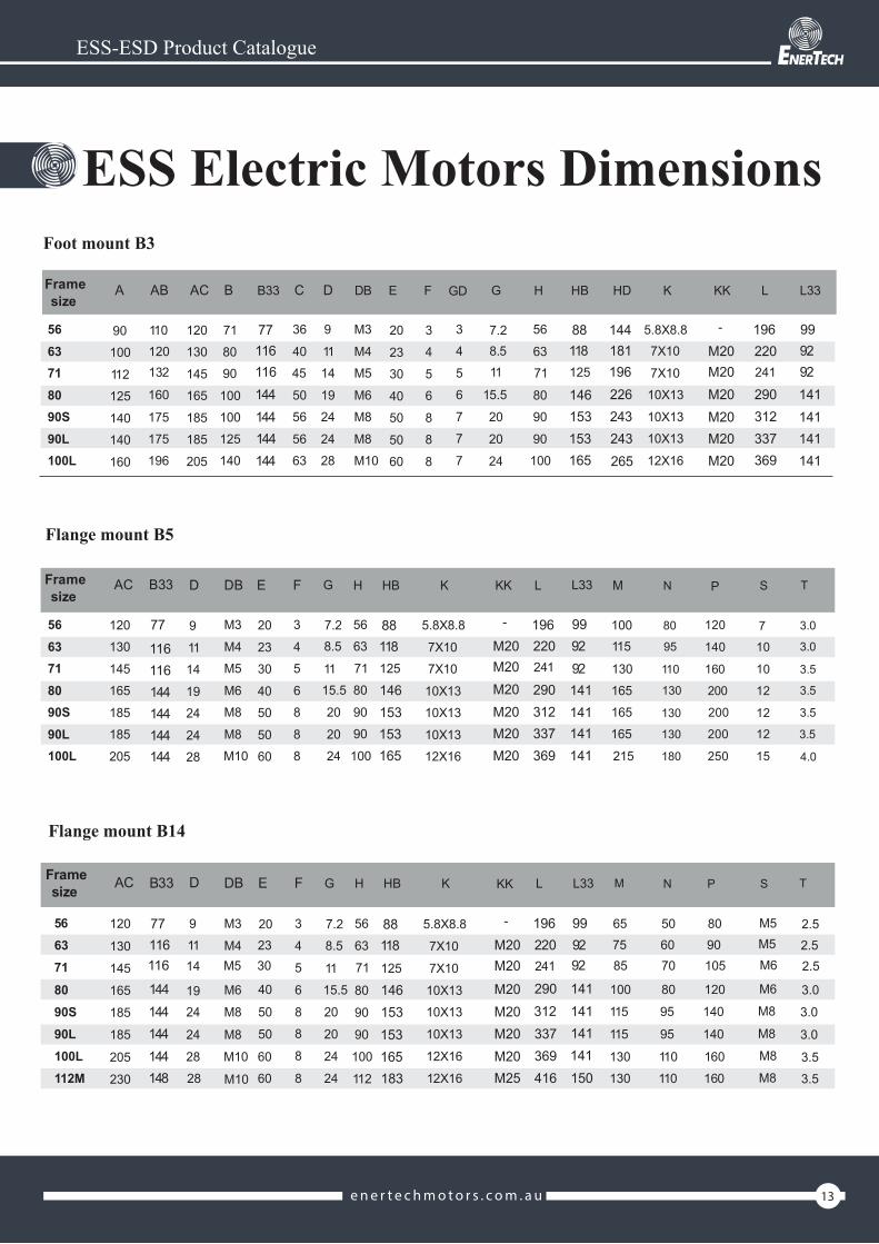
ESS Electric Motors Dimensions
ESS-ESD Product Catalogue
Frame A AB AC B C D DB E F GD G H K
90 110 71 36 9 M3 20 3 3 7.2 56 5.8X8.8
100 120 80 40 11 M4 23 4 4 8.5 63 7X10
112 132 90 45 14 M5 30 5 5 11 71 7X10
125 160 100 50 19 M6 40 6 6 15.5 80 10X13
140 175 100 56 24 M8 50 8 7 20 90 10X13
140 175 125 56 24 M8 50 8 7 20 90 10X13
160 196 140 63 28 M10 60 8 7 24 100 12X16
5663718090S90L100L112M 190 222
120130
145165
185185
205230 140 70 28 M10 60 8 7 24 112 12X16
sizeB33 HD KK L33LHB
77 144 - 9919688116 181 M20 92220118116 196 M20 92241125
144 226 M20 141290146144 243 M20 141312153144 243 M20 141337153144 265 M20 141369165148 295 M25 150416183
Frame AC B33 D DB E F H HB KK L L33 Msize
N P S TKG
5663718090S90L100L112M
120130
145165
185185
205230
77
116116144144144144148
9
1114
1924
2428
28
M3
M4M5
M6M8
M8M10
M10
20
2330
4050
5060
60
3
45
68
88
8
7.28.5
1115.5
20
2024
24
5663
7180
9090
100112
88118125
146153153165183
5.8X8.8
7X107X10
10X1310X13
10X1312X16
12X16
-
M20M20M20M20M20M20M25
196220241
290312337369416
999292141141141141150
100115
130165165165
215
80
95
110
130
130
130
180
180
120
140
160
200
200
200
250
250
7
10
10
12
12
12
15
15
3.0
3.0
3.5
3.5
3.5
3.5
4.0
4.0
Frame M
5663718090S90L100L112M
size N P S T
657585
100
115
115
130130
506070
80
95
95
110110
8090105
120
140
140
160160
M5M5M6
M6
M8
M8
M8
M8
2.52.52.5
3.0
3.0
3.0
3.53.5
AC
120
130
145
165
185
185
205
230
B33
77116116
144144144144148
D
91114
1924
24
2828
DB
M3
M4M5
M6
M8
M8
M10
M10
E
202330
40
50
50
6060
F H HB KK L L33K
3
4
5
6
88
8
8
7.28.5
1115.5
20
20
24
24
G
56
63
71
80
90
90
100
112
88118125
146153153165183
5.8X8.8
7X10
7X10
10X1310X13
10X13
12X16
12X16
-
M20M20
M20M20M20M20M25
196220241
290312337369416
999292
141141141141150

14 ene r t e c hmo to r s . c om . au
ESS-ESD Product Catalogue
Motors dimensions dataFor ESD seriesDimensions foot mount B3
Dimensions flange mount B5 and V1
Dimensions face - flange B14
L33 B33
AB
D
KKH
B
KK
HB

15ene r t e c hmo to r s . c om . au
ESD Electric Motors Dimensions
ESS-ESD Product Catalogue
Frame A AB AC B C D DB E F GD G H K
90 110 71 36 9 M3 20 3 3 7.2 56 5.8X8.8
100 120 80 40 11 M4 23 4 4 8.5 63 7X10
112 132 90 45 14 M5 30 5 5 11 71 7X10
125 160 100 50 19 M6 40 6 6 15.5 80 10X13
140 175 100 56 24 M8 50 8 7 20 90 10X13
140 175 125 56 24 M8 50 8 7 20 90 10X13
160 196 140 63 28 M10 60 8 7 24 100 12X16
5663718090S90L100L112M 190 222
120
130145
165185
185205
230 140 70 28 M10 60 8 7 24 112 12X16
sizeB33 HD KK L33LHB
77 144 - 9919688116 181 M20 92220118116 196 M20 92241125
144 226 M20 141290146144 243 M20 141312153144 243 M20 141337153144 265 M20 141369165148 295 M25 150416183
Flange mount B5
Frame AC B33 D DB E F H HB KK L L33 Msize
N P S TKG
5663718090S90L100L112M
120130145
165185
185205
230
77
116116144144144144148
911
1419
2424
2828
M3M4
M5M6
M8M8
M10
M10
2023
3040
5050
6060
34
56
88
8
8
7.28.5
1115.5
2020
2424
56
6371
8090
90100
112
88118125146153153165183
5.8X8.87X10
7X1010X13
10X1310X13
12X1612X16
-
M20M20M20M20M20M20M25
196220241
290312337369416
999292141141141141150
100115
130165
165165
215
80
95
110
130
130
130
180
180
120
140
160
200
200
200
250
250
7
10
10
12
12
12
15
15
3.0
3.0
3.5
3.5
3.5
3.5
4.0
4.0
Flange mount B14
Frame M
5663718090S90L100L112M
size N P S T
657585
100
115
115
130
130
506070
80
95
95
110
110
8090105
120
140
140
160
160
M5M5M6
M6
M8
M8
M8M8
2.52.52.5
3.0
3.0
3.0
3.5
3.5
AC
120
130
145
165
185
185
205
230
B33
77116116
144144144144148
D
91114
1924
24
28
28
DB
M3
M4M5
M6
M8
M8
M10
M10
E
202330
40
50
50
60
60
F H HB KK L L33K
3
4
56
8
8
8
8
7.2
8.5
1115.520
20
24
24
G
56
63
71
80
90
90
100
112
88118125
146153153165183
5.8X8.87X10
7X10
10X13
10X13
10X13
12X16
12X16
-
M20M20
M20M20M20M20M25
196220241
290312337369416
999292
141141141141150
Foot mount B3

Enjoy the peace of mind