Embed Size (px)
Citation preview


September 1999
Environmental TechnologyVerification Test Protocol
Large Chamber Test Protocol for Measuring Emissions of VOCs and Aldehydes
Prepared by
Research Triangle Institute
Under a Cooperative Agreement with
U.S. Environmental Protection Agency

Notice
This document has been subjected to the U.S. Environmental Protection Agency’s quality assurance and administrative reviews and has been approved for publication.
The EPA, through its Office of Research and Development (ORD), partially funded and managed the extramural research described here under Cooperative Agreement No. CR 822870.
Mention of trade names or commercial products does not constitute endorsement or recommendation by EPA or RTI for use.
This document is copyrighted by Research Triangle Institute; however, the Institute agrees to give to the EPA a non-exclusive, royalty-free, irrevocable license to reproduce and sell the document and to authorize others to do so, too.

Environmental Technology Verification
Large Chamber Test Protocol for MeasuringEmissions of VOCs and Aldehydes
Prepared by
Deborah L. FrankeDavid S. Ensor
Donald A. WhitakerResearch Triangle Institute
Research Triangle Park, NC 27709
EPA Cooperative Agreement No. CR 822870-01
EPA Project Officer: Dr. Leslie SparksNational Risk Management Research Laboratory
U.S. Environmental Protection AgencyResearch Triangle Park, NC 27711

Research Triangle Institute ETV Test Protocol Large Chamber - Emissions of VOCs and Aldehydes Page ii of iv
This page is left intentionally blank.
© Research Triangle Institute, 1999

Research Triangle Institute ETV Test ProtocolLarge Chamber - Emissions of VOCs and Aldehydes Page iii of iv
TABLE OF CONTENTS
TABLE OF CONTENTS . . . . . . . . . . . . . . . . . . . . . . . . . . . . . . . . . . . . . . . . . . . . . . . . . . . . . . . . iiiLIST OF TABLES . . . . . . . . . . . . . . . . . . . . . . . . . . . . . . . . . . . . . . . . . . . . . . . . . . . . . . . . . . . . . iv1 SCOPE . . . . . . . . . . . . . . . . . . . . . . . . . . . . . . . . . . . . . . . . . . . . . . . . . . . . . . . . . . . . . . . . . . 12 REFERENCE DOCUMENTS . . . . . . . . . . . . . . . . . . . . . . . . . . . . . . . . . . . . . . . . . . . . . . . . . 23 TERMINOLOGY . . . . . . . . . . . . . . . . . . . . . . . . . . . . . . . . . . . . . . . . . . . . . . . . . . . . . . . . . . 34 SIGNIFICANCE AND USE . . . . . . . . . . . . . . . . . . . . . . . . . . . . . . . . . . . . . . . . . . . . . . . . . . . 45 ENVIRONMENTAL TEST CHAMBER REQUIREMENTS . . . . . . . . . . . . . . . . . . . . . . . . . . 56 PRODUCT HANDLING . . . . . . . . . . . . . . . . . . . . . . . . . . . . . . . . . . . . . . . . . . . . . . . . . . . . . 67 ENVIRONMENTAL CHAMBER TESTING PROTOCOL . . . . . . . . . . . . . . . . . . . . . . . . . . . 68 CHEMICAL SAMPLING AND ANALYSIS . . . . . . . . . . . . . . . . . . . . . . . . . . . . . . . . . . . . . . 79 EMISSION FACTOR CALCULATIONS . . . . . . . . . . . . . . . . . . . . . . . . . . . . . . . . . . . . . . . . 1510 QUALITY MANAGEMENT . . . . . . . . . . . . . . . . . . . . . . . . . . . . . . . . . . . . . . . . . . . . . . . . . 1611 REPORTING . . . . . . . . . . . . . . . . . . . . . . . . . . . . . . . . . . . . . . . . . . . . . . . . . . . . . . . . . . . . . 16
APPENDIX A. PRODUCT HANDLING . . . . . . . . . . . . . . . . . . . . . . . . . . . . . . . . . . . . . . . . . . A-1APPENDIX B. LABORATORY QUALIFICATIONS AND PROFICIENCY . . . . . . . . . . . . . . . B-1APPENDIX C. QUALITY MANAGEMENT . . . . . . . . . . . . . . . . . . . . . . . . . . . . . . . . . . . . . . . C-1
© Research Triangle Institute, 1999

Research Triangle Institute ETV Test ProtocolLarge Chamber - Emissions of VOCs and Aldehydes Page iv of iv
LIST OF TABLES
Table 1 Potential VOC and Aldehyde Emissions from Office Furniture . . . . . . . . . . . . . . . . . . . . . . 5Table 2 Parameters for VOC Analysis . . . . . . . . . . . . . . . . . . . . . . . . . . . . . . . . . . . . . . . . . . . . 11Table 3 MDL Demonstration . . . . . . . . . . . . . . . . . . . . . . . . . . . . . . . . . . . . . . . . . . . . . . . . . . . 15Table 4 Outline of Report . . . . . . . . . . . . . . . . . . . . . . . . . . . . . . . . . . . . . . . . . . . . . . . . . . . . . . 18Table C-1 Data Quality Indicator Goals for Chamber Test Measurements . . . . . . . . . . . . . . . . . . . . C-2Table C-2 QC Procedures for Emissions Testing . . . . . . . . . . . . . . . . . . . . . . . . . . . . . . . . . . . . . . C-4
© Research Triangle Institute, 1999

Research Triangle Institute ETV Test Protocol Large Chamber - Emissions of VOCs and Aldehydes Page 1 of 18
1.0 SCOPE
1.1 This test method is for the measurement of emissions of aldehydes and volatile organic compounds (VOCs) from products under conditions designed to simulate product use in the indoor environment. Formaldehyde and total volatile organic compounds (TVOC) can be measured in addition to a range of other aldehydes and individual VOCs. Emissions levels are determined by placing the test objects into a large environmental test chamber under specified test conditions then measuring chamber air concentrations of aldehydes and VOCs at selected time intervals. Product-specific emission factors are calculated from the chamber air measurements. The method provides a standard test to reproducibly and accurately measure emissions under controlled laboratory conditions. Commercial furniture was the first application and is used as an example in this test protocol.
1.2 The test objects are taken directly from a manufacturer’s production line. They are packaged and shipped to the test laboratory using the manufacturer’s routine practices. Acquisition, packaging and shipping are discussed in Appendix A of this document. For commercial furniture, Appendix A was specified, and is owned by BIFMA International.
1.3 Aldehydes in chamber air samples are collected on silica gel cartridges coated with 2,4-dinitrophenylhydrazine (DNPH). The DNPH-aldehyde derivatives on the cartridges are eluted with acetonitrile then analyzed by high performance liquid chromatography (HPLC) with ultraviolet (UV) detection. General procedures are outlined in EPA Method TO-11 and EPA Method IP-6A. While the test protocol specifies aldehydes, the buyer, seller, and laboratory may agree to provide only formaldehyde information.
1.4 VOCs in chamber air samples are collected on sorbent cartridges (tubes). VOCs trapped on the cartridges are thermally desorbed then analyzed by gas chromatography/mass spectrometry (GC/MS). Results of these analyses are used to estimate both individual and TVOC concentrations in chamber air samples. While the test protocol specifies speciated VOCs, the buyer, seller and laboratory may agree to only provide TVOC information. General procedures for the use of sorbent cartridges are outlined in EPA Methods TO-1 and TO-11 and EPA IP-1B.
1.5 This is a complex method that requires the use of sophisticated analytical instrumentation and equipment. Proper use of the method requires experience in environmental chamber operation, sorbent system use, and GC/MS analysis for identification and quantitation (or semi-quantitation) of organic species. Individual laboratories performing this method must establish written standard operating procedures (SOPs) for all operations. They must also demonstrate acceptable performance for the entire method. Details for chamber requirements are found in Appendix B of this document.
1.6 It should be stressed that this method is only for the measurement of VOC and aldehyde emissions from objects under surrogate environmental conditions that are consistent with the product’s end use. An assessment of the human health or comfort impact of these emissions in the indoor environment is beyond the scope of the method.
© Research Triangle Institute, 1999

Research Triangle Institute ETV Test Protocol Large Chamber - Emissions of VOCs and Aldehydes Page 2 of 18
2.0 REFERENCE DOCUMENTS
ASTM. D5116-90, Standard Guide for Small Scale Environmental Chamber Determinations of Organic Emissions from Indoor Materials/Products. American Society for Testing and Materials, West Conshohocken, PA, 1990.
ASTM. E741-95, Standard Test Method for Determining Change in a Single Zone by Means of Tracer Gas Dilution, West Conshohocken, PA, 1995.
ASTM. D3195-90 (1994)e1, Standard Practice for Rotameter Calibration. American Society for Testing and Materials, West Conshohocken, PA, 1994.
ASTM. D1356-97a, Standard Terminology Relating to Sampling and Analysis of Atmospheres. American Society for Testing and Materials, West Conshohocken, PA, 1997.
ASTM. E355-96, Standard Practice for Chromatography Terms and Relationships. American Society for Testing and Materials, West Conshohocken, PA, 1996.
ASTM. Manual on Presentation of a Data and Control Chart Analysis, Sixth Edition. American Society for Testing and Materials, West Conshohocken, PA, 1990.
ANSI/ASQC. Specifications and Guidelines for Quality Systems for Environmental Data Collection and Environmental Technology Program, ANSI/ASQC E4, American Society for Quality Control, Milwaukee, WI, 1994.
ANSI/ASQC. Quality Systems—Model for Quality Assurance in Designing, Development, Protection, Installing and Servicing; ANSI/ASQC Q9001-1994, American Society for Quality Control, Milwaukee, WI, 1994. This is the most recent U.S. version of the International Organization for Standards ISO 9001 standard.
Black. Environmental Chamber Methodology for the Study of VOCs Emitting from Manufactured Products, Proceeding of Indoor Air 90, Toronto, August, 1990.
Matthews. Environmental Chamber Test Methodology for Organic Vapors from Solid Emission Sources, ATMOS. Env., 21, p. 321, 1987.
Shewart. 1931. Economic Control of Quality of Manufactured Products, Bell Telephone Labs.
Tichenor. Indoor Air Sources: Using Small Environmental Chambers to Characterize Organic Emissions From Indoor Materials and Products, EPA report 600/8-89-074. This report is available to the public through the National Technical Information Service (NTIS), Springfield, VA 22161, PB90110131.
Tichenor. Organic Emissions from Consumer Product and Building Materials to the Indoor Environment, J of APCA, 38, p. 264, 1988.
© Research Triangle Institute, 1999

Research Triangle Institute ETV Test Protocol Large Chamber - Emissions of VOCs and Aldehydes Page 3 of 18
U.S. EPA. Environmental Technology Verification Program: Quality and Management Plan for the Pilot Period (1995-2000), EPA/600/R-98/064, May 1998. This is available on the EPA website at http://www.epa.gov/etv/.
U.S. EPA. "Test Method for Determining Total Volatile Organic Compound Emission Factors from Carpet Under Defined Test Conditions Using Small Environmental Chambers," EPA Carpet Policy Dialogue Compendium Report, September 27, 1991.
U.S. EPA. Compendium of Methods for Determination of Toxic Organic Compounds in Ambient Air, EPA report 600/4-89/017. This report is available to the public through the National Technical Information Service, Springfield, VA 22161; PB90-116989. This contains EPA TO-1, EPA TO-11 and EPA TO-17. Two supplements to this document are available on the EPA Web site at http://www.epa.gov/clhtml/pubtitle.html.
U.S. EPA. EPA Requirements for Quality Management Plans, EPA QA/R-2. External Review Draft Final, October 1998. Available on the EPA Web site at http://es.epa.gov/ncerqa/qa/qa_docs.html.
U.S. EPA. EPA Requirements for Quality Assurance Project Plans, EPA QA/R-5. External Review Draft Final, October 1998. Available on the EPA Web site at http://es.epa.gov/ncerqa/qa/qa_docs.html.
U.S. EPA. Guidance on Quality Assurance Project Plans, EPA QA/G-5. EPA/600/R-98/018. February 1998. Available on the EPA Web site at http://es.epa.gov/ncerqa/qa/qa_docs.html.
Winberry et al.. Compendium of Methods for the Determination of Air Pollutants in Indoor Air, EPA report 600/4-90/010. This report is available to the public through the National Technical Information Service, Springfield, VA 22161; PB90-200288. This contains EPA IP-1B, EPA IP-6A.
3.0 TERMINOLOGY
3.1 Definitions and Terms Specific to This Standard.
AIR EXCHANGE RATE (ACR). The ratio of the volume of air brought into the chamber hourly and the chamber volume measured in identical units (typically expressed in air changes per hour (ACH) or h-1).
EMISSION FACTOR [mg/(piece · h)] A product specific factor describing the mass of chemical emitted from a product per unit time (where piece indicates the object being tested). The emission factor can also be expressed as the mass of chemical emitted from a product per exposed area of the product per unit time [mg/(m2 · h)]. For commercial furniture, a piece may be a workstation, a chair, or a bookcase.
ENVIRONMENTAL TEST CHAMBER. A test apparatus with highly controlled operational parameters designed to provide accurate and reproducible emission factors for sources of indoor air pollutants.
© Research Triangle Institute, 1999

Research Triangle Institute ETV Test Protocol Large Chamber - Emissions of VOCs and Aldehydes Page 4 of 18
LOADING RATIO (piece(s)/m3). The ratio of number of pieces being tested and the free chamber volume. This can also be expressed as m2/m3, where m2 is the exposed surface area of the test product.
VOLATILE ORGANIC COMPOUND (VOC). Those nonpolar and moderately polar organic chemicals with boiling points between 50 and 280oC that are amenable to monitoring, based on sorbent collection/thermal desorption/GC/MS analysis. The volatility range of chemicals amenable to the method will depend upon the sorbent cartridges and thermal desorption system used by the laboratory.
TOTAL VOLATILE ORGANIC COMPOUNDS (TVOCs). The sum of those VOCs that elute between the retention times of n-pentane and n-hexadecane on a DB-1 (or equivalent) capillary GC column. TVOC concentration is estimated based on a toluene response factor.
4.0 SIGNIFICANCE AND USE
4.1 This protocol provides a standard test for measuring VOC and aldehyde emissions from items under surrogate conditions (i.e., product loading, operational parameters, and environmental conditions) that are consistent with the product’s end use. While Appendix A of this protocol includes the definition of an office workstation, the methods are appropriate for testing emissions from other large objects used indoors.
4.2 The method uses a large environmental test chamber (20–35m3) to evaluate VOC and aldehyde emissions from objects over a specified time period. In testing emissions from smaller pieces, smaller chambers can be used. Considerations within the method and the accompanying appendices include:
4.2.1 Product acquisition and packaging to preserve the integrity of the product with respect to organic emissions;
4.2.2 Product preparation for the emissions test that mimics operations in the indoor environment;
4.2.3 Construction and performance characteristics of the environmental test chamber;
4.2.4 Airflow through and air circulation within the test chamber;
4.2.5 Implementation of the analytical methodology.
4.3 The test method uses a single set of experimental parameters to measure VOC and aldehyde emissions from objects. Care must be taken when extending results from this test method to predict emissions under different sets of conditions . The method does provide a comparison of VOC and aldehyde emissions from different products intended for the same use. A list of potential VOCs and aldehydes that may be emitted from office furniture is included as Table 1. This table is based on frequently reported compounds.
© Research Triangle Institute, 1999

Research Triangle Institute ETV Test Protocol Large Chamber - Emissions of VOCs and Aldehydes Page 5 of 18
Table 1 Potential VOC and Aldehyde Emissions from Office Furniture1
1-Butanol Decane
1,1,1-Trichloroethane Dimethylethanolamine
1,2,3-Trimethylcyclohexane Dodecane
1,2,4-Trimethylbenzene Ethanol
2-Butanone Formaldehyde2
2-Butoxythanol Hexanal2
2-Ethyl-1-hexanol Hexane
2-Methylhexane Limonene
2-Methylpropanol Methanol
3-Methyldecane Naphthalene
3-Methylhexane Nonanal
3,7-Dimethyl-1-octanol Pentanal
4-Ethyltoluene Phenol
Acetaldehyde2 Pinene
Acetic acid Propyl benzene
Acetone Styrene
Butanal2 Toluene
Butyl acetate Undecane
Cyclohexanone Xylenes
Decanal 1 Compounds appearing in >50% of test data. 2 Included in list for DNPH method for aldehydes.Information provided by Dr. Marilyn Black of Air Quality Science.
5.0 ENVIRONMENTAL TEST CHAMBER REQUIREMENTS
As part of this verification program, several laboratories may participate. To ensure that the testing is uniform, a laboratory proficiency program has been established. The laboratories must verify that their environmental test chambers perform according to the requirements of the program. Information on these requirements can be found in Appendix B.
© Research Triangle Institute, 1999

Research Triangle Institute ETV Test Protocol Large Chamber - Emissions of VOCs and Aldehydes Page 6 of 18
6.0 PRODUCT HANDLING
The Environmental Technology Verification Program (ETV) program for indoor air products has used stakeholder groups to provide input to protocols. Industry, their suppliers and customers are included in this group. The commercial furniture industry has provided the information on product definition and handling that can be found in Appendix A.
7.0 ENVIRONMENTAL CHAMBER TESTING PROTOCOL
7.1 Test Conditions
Chamber testing shall be conducted under the following conditions: • Temperature: 23 – 2o C • Relative Humidity: 50 – 5% • Air Exchange Rate: 1.0 – 0.1 hr-1
• Pressure: between 0 and + 2.5 cm water.
7.2 Prior to placing the test product in the chamber, background air samples shall be collected from the chamber to assess background chemical levels. This involves adjusting the chamber flow conditions, temperature, and relative humidity to the standard test conditions given in Section 7.1. The chamber is then closed and allowed to equilibrate for at least 4 hours at which time background air samples for the analysis of aldehydes and VOCs are collected and analyzed using the procedures described in Appendix B. Background levels must not exceed 2 µg/m3
formaldehyde, 10 µg/m3 of TVOC, and 2 µg/m3 of any individual VOC.
7.3. Concurrent with the background sampling, a tracer gas release shall be made to determine the air exchange rate as described in Appendix B, Section 2.5.1. If historical chamber data is not available, perform QC requirement of air exchange and mixing confirmation.
7.4 The test objects shall be unpacked and assembled as much as possible outside the chamber. They shall then be placed into the chamber and assembly completed as described in Appendix A. Assembly in the chamber shall be completed in 8 hours or less.
7.5 Once assembly is complete, the chamber shall be closed.
7.6 The emissions test shall start when the door is closed, which is defined as time T = 0. Chamber air samples for aldehydes and VOCs will be collected at T = 4, 8, 24, 48, 72, 96, and 168 hours. If agreed upon by manufacturer, buyer, and laboratory, a different number of air samples may be collected and analyzed or different time points may be used.
© Research Triangle Institute, 1999

Research Triangle Institute ETV Test Protocol Large Chamber - Emissions of VOCs and Aldehydes Page 7 of 18
8.0 CHEMICAL SAMPLING AND ANALYSIS
8.1 Standard Operating Procedures
Quality management is an important part of the ETV process. This requires all participating laboratories to fully document their SOPs. A full discussion of the required quality management and SOPs can be found in Appendix C.
8.2 Aldehydes
General procedures for the sampling and analysis of target aldehydes in chamber air samples are outlined in EPA Method TO-11 and EPA Method IP-6A. Alternative methods may be used if similar performance can be demonstrated for all of the target aldehydes. TO-11 can be found in U.S. EPA. Compendium of Methods for Determination of Toxic Organic Compounds in Ambient Air, EPA report 600/4-89/017 and IP-6A can be found in Winberry et al.. Compendium of Methods for the Determination of Air Pollutants in Indoor Air, EPA report 600/4-90/010. Both documents are available from NTIS (see references, Section 2.0).
8.2.1 Collection Media. Aldehydes in chamber air samples are collected on DNPH-coated silica gel cartridges. Commercially prepared cartridges are available from several sources. It is recommended that these commercial cartridges be used. Ozone may interfere with the analysis of formaldehyde using this method. If this is shown to be a problem during chamber tests, then potassium iodide scrubbers or denuders should be used to remove ozone from the air stream prior to sample collection. For consistency between laboratories and to avoid the requirement that ozone is not a problem for the large chamber being used, the use of the ozone scrubber during sampling with DNPHcoated silica gel cartridges is required.
8.2.2 Cartridge Preparation. DNPH-silica gel cartridges are ready to use as received from the manufacturer. Cartridges shall be stored in a refrigerator according to manufacturer’s recommendation until used. For sampling, cartridges shall be removed from the refrigerator and allowed to warm to room temperature. No additional preparation is necessary. A minimum of three blank cartridges shall be analyzed from each batch of 50 cartridges to assess the cartridge background. To be considered acceptable, cartridges must show no more than 50 ng/cartridge for total aldehydes.
8.2.3 Collection of Chamber Air Samples. Calibrated air pumps or mass flow controllers located outside the chamber are used to pull chamber air through sampling cartridges mounted in the chamber sampling port. Aldehyde samples are collected through nonabsorbent tubing (stainless steel). Sampling lines shall be purged with at least five volumes of chamber air prior to connecting the sampling cartridges. Air samples are collected at a flow rate sufficient to provide a nominal sampled volume of 30-40 L. Pump flow rates are based on the duration of sampling and the desired total sample volume. A
© Research Triangle Institute, 1999

Research Triangle Institute ETV Test Protocol Large Chamber - Emissions of VOCs and Aldehydes Page 8 of 18
flow of approximately 300 mL/min for a 2-hour period provides a nominal sample volume of 36 L. Sampling instructions should follow the guidance of the cartridge manufacturer.
Flow rate measurements shall be made at the beginning and end of each sample collection period using a National Institute of Standards and Technology (NIST) traceable flow device.
8.2.4 Sample Storage. Once samples are collected, exposed cartridges shall be capped with the end caps provided with the cartridges. Cartridges shall then be sealed in a secondary container and stored in a freezer at -20 oC or as recommended by the cartridge supplier. Samples may be stored up to 3 weeks prior to extraction and analysis, or following manufacturer's recommendations. They must be protected from sunlight.
8.2.5 Sample Analysis.
8.2.5.1 DNPH/aldehyde derivatives on sample cartridges shall be extracted by eluting each cartridge with 5.0 mL of HPLC grade acetonitrile into a 5.0 mL volumetric flask. The final volume shall be adjusted to 5.0 mL and the sample aliquoted for analysis. Blank cartridges shall be eluted with each sample set to evaluate background contaminants. Additional blank cartridges shall be spiked with known amounts of DNPH/aldehyde standards as a method of assessing recovery.
8.2.5.2 DNPH/aldehyde derivatives in sample extracts shall be analyzed by HPLC with UV detection at 360 nm using a C18 column and gradient elution. Use mobile phases and a gradient recommended by the DNPH cartridge manufacturer or determined by the laboratory to be adequate. Mobile phase A will generally consist of water/acetonitrile/tetrahydrofuran in the ratio of 60/30/10 (v/v) and mobile phase B will generally consist of water/acetonitrile in the ratio of 40/60 (v/v). The gradient will generally begin as 100% of mobile phase A held for 1 minute followed by a linear gradient over 10 minutes to 100% mobile phase B. The mobile phases and the gradient can be adjusted by the laboratory to optimize the analytical results.
8.2.6 Quantitation and Identification of Target Analytes These shall be based on the analysis of calibration standards of the DNPH/aldehyde derivatives.
8.2.6.1 Purified and certified DNPH derivatives of the target aldehydes shall be used for the preparation of calibration standards in the range of 0.02–15 ng/µL. Standards shall be analyzed singly for the aldehyde/DNPH derivatives and a calibration curve calculated by linear regression of the concentration and chromatographic response data. Calibration curves for all target analytes must have r2 > 0.995. In addition, the measured concentration of the aldehyde/DNPH derivatives in each standard must be within 85–115% of the prepared concentrations.
© Research Triangle Institute, 1999

Research Triangle Institute ETV Test Protocol Large Chamber - Emissions of VOCs and Aldehydes Page 9 of 18
8.2.6.2 To demonstrate ongoing instrumental performance, a calibration standard shall be analyzed each day prior to the analysis of any samples and after every eight samples. The calibration will be considered in control if the measured concentration of the aldehyde/DNPH derivative in the standard to within 85–115% of the prepared concentration.
8.2.6.3 Target analytes in sample extracts shall be identified by comparison of their chromatographic retention times with those of purified standards. For a positive identification, the retention time of the unknown in the sample extract must be within 0.5 minutes of the retention time of the DNPH/aldehyde derivative in the most recently analyzed standard.
The concentration of DNPH/aldehyde derivatives in sample extracts shall be calculated from the calibration curve using the chromatographic peak area. The concentration of aldehydes in chamber air samples shall be calculated as:
C x = C y ·V y · D F (1)V s
where
Cx = Concentration of aldehyde in the chamber air sample (ng/L or µg/m3)
Cy = Concentration of DNPH/analyte derivative in the sample extract (ng/ µL)
Vy = Total volume of sample extract (i.e., 5000 µL) Vs = Sample volume in liters (L) DF = Molecular weight of analyte / molecular weight of
analyte/DNPH derivative.
8.2.7 Performance Requirements. Quality control (QC) procedures and laboratory performance requirements for the analysis of aldehyde samples in chamber air samples are given in Appendix C, Table C-2.
8.3 Volatile Organic Compounds (VOCs)
8.3.1 Overview. VOCs in chamber air samples are collected on sorbent cartridges. VOCs trapped on the cartridges are thermally desorbed then analyzed by GC/MS. General procedures for the use of sorbent cartridges are outlined in EPA Methods TO-1, TO-17, and IP-1B. The specific sorbent cartridges for sample collection and the procedures for thermal desorption and introduction into the GC/MS are not specified in this method. Rather, the test laboratory can select a procedure that is compatible with its instrumentation and current practices. The procedures for VOC analysis are performance-based, and each laboratory must demonstrate that it can meet the performance specifications detailed in this method.
© Research Triangle Institute, 1999

Research Triangle Institute ETV Test Protocol Large Chamber - Emissions of VOCs and Aldehydes Page 10 of 18
8.3.2 Collection Media. VOCs in chamber air samples are collected on sorbent cartridges. Cartridges are available commercially from several sources, and laboratories will supply their own pre-cleaned cartridges.
8.3.3 Cartridge Preparation. Commercially purchased sorbent cartridges shall be cleaned prior to use following the recommended manufacturer’s procedures. Typically, cartridges will be thermally desorbed under an inert gas flow as preparation for sampling. Cleaned cartridges shall be stored in sealed containers in a clean area to minimize contamination. A minimum of 10% of the cleaned cartridges shall be randomly selected for background analysis by GC/MS. To be considered acceptable, cartridges must show no more than 10 ng/cartridge for individual VOCs. TVOC must be less than 50 ng/cartridge. Batches that do not meet background criteria shall be recleaned and rechecked.
8.3.4 Collection of Chamber Air Samples. Calibrated air pumps or mass flow controllers located outside the chamber are used to pull chamber air through the sampling cartridges mounted in the chamber sampling port. Sampling lines and ports should be nonabsorbent tubing (stainless steel). Sampling lines shall be purged with at least five volumes of chamber air prior to connecting the sampling cartridges. Air samples are collected at a flow rate sufficient to provide a nominal sampled volume of 5–20 L. Pump flow rate is based on the duration of sampling and the desired total sample volume. A flow of approximately 100 mL/min for a 1-hour period provides nominal sample volumes of 6 L.
Sampling pump or mass flow controller flow rate measurements shall be made at the beginning and end of each sample collection period. A NIST-traceable flow device shall be used.
8.3.5 Sample Storage. Once samples are collected, exposed cartridges shall be individually sealed in storage tubes. The tubes containing these cartridges shall be stored in a freezer at -20oC or as recommended by cartridge supplier in a manner that will minimize sample contamination. Samples may be stored up to 3 weeks prior to analysis.
8.3.6 Sample Analysis
8.3.6.1 Operating Conditions. VOC analysis shall be conducted by high-resolution gas chromatography coupled with mass spectrometry using the general conditions shown in Table 2. The VOCs sorbed on the sample cartridge shall be efficiently desorbed and injected onto the GC column using a well controlled, reproducible, thermal desorption system.
8.3.6.2 MS Mass Calibration. Tuning and mass calibration of the MS is performed according to the manufacturer’s instructions, generally using perfluorotributylamine (FC-43). This process may vary among instruments. The FC-43 is introduced directly into the ion source through a molecular leak. Instrumental parameters are automatically adjusted following the sequence below to give acceptable relative ion abundance of:
© Research Triangle Institute, 1999

Research Triangle Institute ETV Test Protocol Large Chamber - Emissions of VOCs and Aldehydes Page 11 of 18
Mass % Relative Abundance 69 100 131 >35 219 >24 502 >1
TABLE 2. Parameters for VOC Analysis
Parameter Specification
Sorbent Type: Laboratory selected
Thermal Desorber: Laboratory selected
Gas Chromatography - Column Type: - 25 to 60 m DB-1 or equivalent fused silica capillary column - Chromatographic Conditions: - Laboratory selected, to capture n-pentane to hexadecane
accurately and reproducibly
Mass Spectrometer - Ionization Mode: - Electron ionization and 70 eV - Mass Range: - 35 to 450 m/z - Scan Cycle Time: - 0.5 to 1.0 second
8.3.6.3 Instrument Calibration. Prior to analysis, a blank cartridge shall be analyzed to verify that the analytical system is free from contamination. Five standard cartridges shall then be analyzed to establish GC retention time windows for VOC analysis, to generate instrumental response factors for quantitative measurements and to verify method detection limits (MDLS). Standard cartridges shall be spiked as follows:
• Toluene - (spiked at 100, 200, 400, 600, and 800 ng/cartridge) High-level spikes used to generate response factors for TVOC analysis, used to generate response factor for quantitating toluene during chamber recovery experiments and from control cartridges.
• n-Decane - (spiked at 100, 200, 400, 600, and 800 ng/cartridge) Highlevel spikes used to evaluate instrumental response and stability for VOC with varying physical/chemical properties, used to generate response factor for quantitating n-decane during chamber recovery experiments and from control cartridges.
• Cyclohexane - (spiked at 100, 200, 400, 600, and 800 ng/cartridge) Highlevel spikes used to evaluate instrumental response and stability for VOC with varying physical/chemical properties, used to generate response factor for quantitating cyclohexane during chamber recovery experiments and from control cartridges.
• 1-Hexanol - (spiked at 100, 200, 400, 600, and 800 ng/cartridge) Highlevel spikes used to evaluate instrumental response and stability for VOC
© Research Triangle Institute, 1999

Research Triangle Institute ETV Test Protocol Large Chamber - Emissions of VOCs and Aldehydes Page 12 of 18
with varying physical/chemical properties, used to generate response factor for quantitating 1-hexanol during chamber recovery experiments and from control cartridges.
• n-Pentane - (spiked at any level from 100 to 800 ng/cartridge) used to establish retention time windows for TVOC determinations.
• n-Hexadecane - (spiked at any level from 100 to 800 ng/cartridge) used to establish retention time windows for TVOC determinations.
• External quantitation standard - spiked onto each calibration, sample, blank, and control cartridge at the same level (~200 ng/cartridge), used to generate response factors and for sample quantitation, also used to evaluate instrumental sensitivity; recommended external quantitation standards include perfluorotoluene (PFT), bromofluorobenzene (BFB), or bromofluorotoluene (BFT).
Calibration and sample quantitation shall be accomplished using chromatographic peak areas derived from reconstructed ion chromatograms (RIC). For each calibration cartridge, relative response factors (RRF) will be calculated as:
SRRF T = AT · M Q (2)AQS
· M T
where
MT = mass of target analyte (ng/cartridge)MQS = mass of quantitation standard (ng/cartridge)AT = peak area of the target analyteAQS = peak area of the quantitation standard.
Mean values and standard deviations of the RRFs will be calculated for each target VOC using results from analysis of the four high-level calibration cartridges. Calibration will be considered acceptable if the standard deviation for each RRF is less than 20%.
Chromatographic efficiency shall be checked using 1-hexanol on the mid-level calibration standard. VOCs are introduced into the chromatographic system as a discrete sample. To ensure acceptable injection, the width of each peak at 10% of its height should not exceed 10 seconds for n-pentane, 1-hexanol, toluene, ndecane, n-hexadecane, and the external quantitation standard.
8.3.6.4 Preparation of Standard and Control Cartridges. Standard cartridges may be prepared using Tenax® or multisorbent cartridges. VOC analytes (Section 8.3.6.3) shall be loaded onto the cartridges using either flash evaporation from a methanol solution or gas phase loading using permeation devices, a gas mixing bulb, standard gas canisters, or standard gas cylinders. Note: If a methanol solution is flash loaded onto a multisorbent cartridge to prepare standards, it must
© Research Triangle Institute, 1999

Research Triangle Institute ETV Test Protocol Large Chamber - Emissions of VOCs and Aldehydes Page 13 of 18
be demonstrated that the multisorbent cartridge is not adversely affected by the methanol. Cartridges containing Tenax® only are generally not affected.
Control cartridges shall be prepared using the same multisorbent cartridges as used for collecting chamber air samples. These cartridges shall be loaded with toluene, n-decane, 1-hexanol, and cyclohexane at ~400 ng/cartridge. For most multisorbent tubes, loading is most effective from gas phase standards using either permeation devices, gas mixing bulbs, or gas canisters or cylinders. Flash loading using methanol solutions may be used if acceptable performance can be demonstrated.
External standards shall be loaded onto all sample, calibration, blank, and control cartridges using gas phase standards.
8.3.6.5 Sample Cartridge Analysis. During each day of analysis, an additional mid-level cartridge calibration shall be analyzed as a response factor check. If the RRF values for this standard (for toluene, n-decane, cyclohexane, and 1-decanol) are within – 20 % of the RRFs obtained during the instrument calibration, the GC/MS system will be considered in control. The criteria for chromatographic efficiency and peak width as described in Section 8.2.6.3 shall also be met.
8.3.6.6 Identification and Quantification of TVOC. The TVOC shall be calculated using the total area of the RIC integrated within the retention time window from n-pentane to n-hexadecane (ATVOC). The TVOC mass [MTVOC] will be calculated based on the average total ion relative response factor generated for toluene (RRFTol). Chamber air concentrations will be calculated by dividing mass per cartridge by sample volume:
RRFA MA=M
TolQS
QSTVOC TVOC ·
· (3)
where MTVOC = TVOC mass (ng/cartridge) MQS = mass of quantitation standard (ng/cartridge) RRF Tol = average ion relative response factor for toluene ATVOC = TVOC peak area AQS = peak area of the quantitation standard.
8.3.6.7 Identification and Quantification of Individual VOCs. For qualitative analysis, individual VOCs in the GC/MS chromatogram are identification by comparing the mass spectrum of the sample component to a library reference spectrum (e.g., NIH/EPA/MSDC Mass Spectral Data Base and the Registry of Mass Spectral Data). This is most effectively accomplished using an electronic database search with manual verification of results. Quantitative mass estimates (MIVOC) for
© Research Triangle Institute, 1999

Research Triangle Institute ETV Test Protocol Large Chamber - Emissions of VOCs and Aldehydes Page 14 of 18
individual VOCs will be made from the RIC area (AIVOC) and the RRF for toluene as:
· M IVOC = AIVOC M QS . (4)
·AQS RRF Tol
For the purpose of this protocol, the response factor of toluene is used to determine semi-quantitative or estimated mass/concentration of the individual VOCs. This method assumes that the responses of the identified compounds are the same as toluene. This is to simplify and reduce the costs of performing the analysis. If quantitatively accurate mass/concentration values are to be determined, a target list of specific compounds for which individual calibration standards can be prepared must be determined and agreed upon by the manufacturer and analytical laboratory. Since this list of compounds will be product specific, expected target compounds must be based on historical data, on screening samples collected and analyzed for the product of interest, or compiled from a list of possible compounds. Chamber air concentrations will be calculated by dividing by sample volume.
8.3.7 Performance Requirements. Quality control procedures and performance requirements for the analysis of VOCs in chamber air samples are detailed in Appendix C, Table C-2.
8.4 Method Detection Limits
The MDL is the minimum concentration at which a chemical can be quantitatively identified and measured in a sample with acceptable accuracy and precision. Concentration values should not be reported below the MDL. Generally, MDLs are developed by a laboratory and are then applied to the data generated by that laboratory. For this ETV program, where multiple laboratories may be performing the analysis, the use of laboratory-specific MDLs will affect the comparability of the data.
With a program-specific MDL, each participating laboratory must first demonstrate the ability to meet or exceed the MDL requirement. Continuing checks on MDL performance should be conducted whenever the instrument is calibrated. For both VOCs and aldehydes, the demonstration of the MDL shall be based on the variability of the measured concentration in replicate samples containing low concentrations of the chemicals of interest. This procedure takes into account the performance of the entire method, not just the analytical system.
For these measurement parameters, MDLm in ng/cartridge is calculated as:
MDLm = 3 · SD (5)
where SD is the standard deviation of the measured concentration determined during the analyses of replicate samples. At a minimum, seven replicate samples should be analyzed. MDLc as µg/m3 is calculated by dividing MDLm by the volume of chamber air used for sample collection.
© Research Triangle Institute, 1999

Research Triangle Institute ETV Test Protocol Large Chamber - Emissions of VOCs and Aldehydes Page 15 of 18
Table 3 shows the VOCs and aldehydes for MDL determinations, the spiking levels recommended, and the MDL requirements.
Continuing checks on laboratory MDLs will be based on a low-level standard analyzed during calibration. To verify the MDL, all analytes in the lowest level calibration standard must be detected with signal-to-noise ratio of 10 to 1.
Table 3. MDL Demonstration
Analytes Spike Level MDLc Requirement (ng/cartridge) (µg/m3)
VOCs Toluene 5 - 10 2 (0.52 ppb) n-decane 5 - 10 2 (0.34 ppb) cyclohexane 5 - 10 2 (0.57 ppb) 1-hexanol 5 - 10 2 (0.47 ppb)
Aldehydes Formaldehyde 100 6.3 (5 ppb)
9.0 EMISSION FACTOR CALCULATIONS
9.1 Dynamic chamber testing, as described in this method, provides for the calculation of emission factors for vapor phase organic compounds. The calculation procedure depends on the behavior over time of the source being tested. For the purposes of this method, it is assumed that sources have either constant emission factors or emission factors that exhibit first-order decay over time.
9.2 For sources with constant emissions, once the chamber concentration reaches a steady state, the emission factor is calculated as:
��Ł
N��ł
EF = C (6)L
where EF = emission factor, mg/(piece . h) [or mg/(m2.h] C = chamber concentration, mg/m3
N = chamber air exchange rate, h-1
L = product loading, piece/m3 (or m2/m3).
© Research Triangle Institute, 1999

Research Triangle Institute ETV Test Protocol Large Chamber - Emissions of VOCs and Aldehydes Page 16 of 18
9.3 For sources with an emission factor having a first-order decay, the emission factor is:
EF = EF e-kt (7)i
where EFi = initial emission factor, mg/(piece.h) [or mg/(m2.h)] k = first-order decay constant, h-1
t = time, h.
EFi and k are determined by fitting the following equation to the chamber concentration vs. time data:
C = L( EF )( e -kt - e-Nt ) / (N - k) (8)i
where C = chamber concentration, mg/m3
EFi = initial emission factor, mg/(piece.h) [or mg/(m2.h)] k = first order rate constant, h-1
t = time, h (midpoint of the sampling interval) N = air exchange rate in h-1
L = product loading, piece/m3 [or m2/m3].
10.0 QUALITY MANAGEMENT
Quality management is covered in Appendix C.
11.0 REPORTING
The purpose of the test report is to provide the reader the information necessary to understand the conduct of the tests and to assess and interpret the results. To meet these objectives, a complete description of the test objectives; facilities and equipment; experimental design; sample descriptions; experimental procedures; data analysis; results; discussion; and conclusion; and quality assurance/quality control program shall be included.
11.1 The contents of the test report shall include all aspects of the test program relevant to interpretation of results. The report shall be comprehensive and inclusive rather than omitting detail, yet it should be presented as concisely as possible.
11.1.1 Testing Laboratory Identification. Provide name, address, phone number, and contact person for the reported testing activity.
11.1.2 Test Objectives. Define the purpose of the testing project and the intended use of the results.
© Research Triangle Institute, 1999

Research Triangle Institute ETV Test Protocol Large Chamber - Emissions of VOCs and Aldehydes Page 17 of 18
11.1.3 Facilities and Equipment. Describe the test chambers, clean air system, environmental measurement and control, sample collection, analytical instrumentation, and standards generation and calibration.
11.1.4 Experimental Design. Describe test conditions, including temperature, humidity, air exchange rate, and test materials loading. Include a test matrix listing the test condition and test sample variables and their combinations in the experiment.
11.1.5 Sample Description. Provide sample description and any given information, including, but not limited to, type of material, product history, etc., and sample selection process (e.g. random). Provide information on sample acquisition procedures, sample packaging, storage, transport, and handling upon arrival at the laboratory. Describe environmental conditions and duration of each phase of the process from acquisition until testing.
11.1.6 Experimental Procedures. Describe the experimental procedures used during testing, including details of the sampling and analysis techniques and references to published methods whenever used. Describe the timing of air sample collection in relation to the placement of the test specimen in the chamber and operation of the environmental control system for the chamber. Provide the dates for testing and the duration of exposure.
11.1.7 Data Analysis. Show or reference the methods, including appropriate models or equations, used to analyze the chamber data to obtain emission factors or emission rates.
11.1.8 Results. Provide emission factors for each type of sample tested and for each environmental condition evaluated. The sampling time shall be reported as the mid-point of the sample collection. Emission factors can be provided for individual organic compounds and/or total organics. Where total organics are reported, include a description or reference of the method of quantification. Where variable rates are measured, provide a rate constant and describe the calculation method by which it is derived. Describe the accuracy and precision bounds of the test results.
11.1.9 Discussion and Conclusion. Present the requested results. If required, discuss the relevance of the findings and provide conclusions. For example, describe the effect of temperature and/or air exchange rate on emission factors. Note any anomalies and describe data treatment to address such data.
11.1.10 Quality Assurance/Quality Control. Summarize the overall data quality achieved including the results of the internal QC checks. All limitations or constraints on the use of the data, the results of the audits, and any corrective actions will be discussed in the QA/QC section of the reports.
11.1.11 Reporting Format. A sample outline for the report is included in Table 4.
© Research Triangle Institute, 1999

Research Triangle Institute ETV Test Protocol Large Chamber - Emissions of VOCs and Aldehydes Page 18 of 18
Table 4 Outline of Report
Front Matter Title Page(s)AbstractTOC, List of Figures, List of TablesAbbreviations and Acronyms
Body Section 1 Executive Summary
Section 2 IntroductionSection 3 Test Program
Participating Laboratories Test Objectives Testing Facilities and Equipment
Section 4 Test ProtocolApproachExperimental Design
Section 5 Testing and Results Sampling and Experimental Procedures Data Analysis and Routine Quality Assessment Results and Discussion
Section 6 Quality AssuranceSection 7 Conclusions/Summary
End Matter ReferencesAppendices
© Research Triangle Institute, 1999

Research Triangle Institute ETV Test Protocol Large Chamber - Emissions of VOCs and Aldehydes Page A 1 of A1
APPENDIX A. PRODUCT HANDLING In the draft version of the protocol used for protocol verification testing, Appendix A, Product Handling was defined and owned by BIFMA, Intl. This material is now outdated. For information on product specification, procurement and handling, please contact
BIFMA International2680 Horizon Dr. S.E., Suite A-1Grand Rapids, MI 49564(616) 283-3963.

Research Triangle Institute ETV Test Protocol Large Chamber - Emissions of VOCs and Aldehydes Page B 1 of B4
APPENDIX B. LABORATORY QUALIFICATIONS AND PROFICIENCY
This Section is Owned and Specified by RTI and EPA
1.0 LABORATORY PROFICIENCY
Laboratories taking part in this program must comply with the quality management requirements defined in Appendix C, including outside audits by RTI and EPA. In addition, it is expected that each laboratory will take part in a round-robin testing program among all the participating laboratories.
2.0 ENVIRONMENTAL TEST CHAMBER REQUIREMENTS
2.1 The tests shall be conducted in a single environmental test chamber capable of accommodating the object in its entirety when it is assembled according to manufacturers’ specifications. The interior volume of the chamber should range from 20 to 35 m3.
2.2 Air shall be supplied to the chamber using a single pass system. The volume of air that flows through the chamber shall be at a constant volume that provides 1.0 – 0.1 ACH, and will depend on the chamber size. If a chamber with an interior volume of 21 m3 is used, then the airflow shall be 21 m3/h. Likewise, if a chamber with an interior volume of 29 m3 is used then the airflow shall be 29 m3/h. Note: Operation of excessively large chambers to meet this requirement may excessively dilute the emissions.
2.3 The environmental test chamber shall be constructed of inert, smooth surfaces such as stainless steel, aluminum or glass. All joints and openings shall be sealed. All seals shall be made of non-VOC emitting and non-VOC adsorbing/absorbing materials. The surfaces and seals of the chamber shall be sufficiently chemically inert such that formaldehyde at the level of 0.05 ppm and representative VOCs at the level of 10 µg/m3 are not irreversibly retained on the interior surfaces. Quality control testing must demonstrate recoveries of 80 to 120% for formaldehyde, toluene, and n-decane spiked at these levels. Recoveries of these compounds shall be demonstrated within 12 months prior to the emissions test.
2.4 The air within the chamber shall be free of any obstructions or contamination such as humidifiers or refrigeration coils. Internally or externally mounted fans may be used to keep the chamber air well mixed if it can be demonstrated through the use of quality control samples that the fans do not contaminate the chamber air samples or irreversibly absorb/adsorb formaldehyde or representative VOCs (toluene and n-decane). The internal chamber air shall only come in contact with inert materials.
2.5 The air within the chamber shall be well mixed and comply within 5% of the theoretical well mixed model. Mixing shall be evaluated in an empty chamber. It shall be evaluated within 6 months prior to testing. Several procedures as described below may be used to evaluate chamber
© Research Triangle Institute, 1999

Research Triangle Institute ETV Test Protocol Large Chamber - Emissions of VOCs and Aldehydes Page B 2 of B4
air mixing. If CO is used as the tracer gas, the laboratory should follow precautions to its use as it is hazardous.
2.5.1 An inert tracer gas (SF6 or CO) is introduced into the chamber (preferably with the inlet air) at a constant known concentration and flow. The chamber air concentration of the tracer gas is then measured over time at the same location as the sampling ports. The experimental curve (concentration vs. time) is compared to the theoretical curve for the same variables, assuming complete mixing by estimating the relative standard deviation (RSD) of the mean of the deviation of the difference between the observed and theoretical air concentrations at selected time points. An estimate of the variance (s2) is:
(o - t )2
s2 = S (B-1)n - 1
where
o = observed valuet = theoretical valuen = number of observations.
The mean of the differences would be:
S (o - t)m = . (B-2)
n
The RSD is then:
RSD = s / m . (B-3)
Using this approach, the chamber air is considered well mixed if the RSD is less than 5%.
2.5.2 An inert tracer gas (SF6 or CO) is introduced into the chamber (preferably with the inlet air) at a constant known concentration and flow. The chamber air concentration of the tracer gas is then measured over time at the same location as the sampling ports. The chamber concentration vs. time plot is compared to the theoretical curve for a completely mixed chamber:
C = Co (1 - e-Nt ) (B-4) where
C = chamber concentration,Co = inlet concentration,t = timeN = air exchange rate, N = Q/V, where Q = flow rate through chamberV = chamber volume.
© Research Triangle Institute, 1999

Research Triangle Institute ETV Test Protocol Large Chamber - Emissions of VOCs and Aldehydes Page B 3 of B4
To evaluate mixing, the chamber volume (V) then is estimating by fitting the air concentration data for the tracer gas to the theoretical curve. The chamber air is considered well mixed if the actual chamber volume and the chamber volume estimated from the tracer gas concentration agree within 5%.
2.5.3 An inert tracer gas (SF6 or CO) is introduced into the chamber (preferably with the inlet air) over a short period of time (1 to 10 minutes). The chamber air concentration of the tracer gas is then measured over time at least two and preferably three locations within the chamber. One location must be at the sampling ports; other locations should be at least 6 to 8 feet away from the first location. Chamber air exchange rates (air changes per hour) are calculated from tracer gas decay measurements as:
ACH = 1/ (t o - ti ) ln (C i / C o ) (B-5)
where
ACH = air changes per hourto = final time (elapsed time in hours)ti = initial time Ci = initial tracer gas concentration in ppmCo = final tracer gas concentration in ppm.
The chamber air is considered well mixed if the calculated air exchange rates at the different locations agree within 5%.
2.6 Sampling ports for collecting chamber air samples may be located in the chamber outlet exhaust. Alternatively, sampling ports may be affixed to the chamber walls; these ports should be at an elevation of at least 0.5 m (19.7 in.) with lines that extend at least 10 cm (6 in.) from interior walls of the chamber. Sampling lines shall be made of nonabsorbent material, such as stainless steel. Sampling ports and lines shall be located in a way that does not adversely affect the chamber airflow.
2.7 Purified air shall be supplied to the chamber. It is necessary that the supply air background is sufficiently low to achieve statistically meaningful analytical measurements at the chamber air concentrations anticipated during product testing. Background concentrations in purified air shall not exceed 2 µg/m3 formaldehyde, 10 µg/m3 for TVOC, and 2 µg/m3 for any individual VOCs. The background in the chamber air shall also not exceed these levels. Background measurements of chamber air samples shall be sampled and analyzed just prior to loading the product into the chamber.
2.8 The environmental test chamber shall be operated under a slight positive pressure (less than 2.5 cm (1 inch) of water) relative to atmospheric pressure.
2.9 Appropriate instrumentation shall be incorporated into the environmental chamber system to control and monitor air exchange rate, temperature, and relative humidity. The instrumentation
© Research Triangle Institute, 1999

Research Triangle Institute ETV Test Protocol Large Chamber - Emissions of VOCs and Aldehydes Page B 4 of B4
must have adequate accuracy, precision, and sensitivity to control these parameters and to document that the emission test is conducted within the control limits set in Section 7.1.
2.9.1 Temperature and relative humidity shall be monitored continuously throughout the test period.
2.9.2 At a minimum, air exchange rate shall be monitored immediately before the product is placed in the chamber (at the same time background contamination checks are made) and each time chamber air samples are collected. Air exchange rate may be monitored by accurately measuring the air flow into the chamber. ACH (h-1) is then calculated as air flow (m3/h) divided by chamber volume (m3). The accuracy of this air exchange rate must be confirmed (within 10% accuracy) using procedures similar to that presented in ASTM Method E741 for tracer gas application. Alternatively, ASTM Method E741 may be used as the primary method for determining air exchange rate. A list of VOC and aldehyde compounds that may be found is shown in Table 1.
© Research Triangle Institute, 1999

Research Triangle Institute ETV Test Protocol Large Chamber - Emissions of VOCs and Aldehydes Page C 1 of C6
APPENDIX C. QUALITY MANAGEMENT
1.0 QUALITY MANAGEMENT
As part of the ETV program, EPA has developed a quality management plan (QMP) for EPA and the verification partners. This document follows the ANSI/ASQC E4 guidelines. The ETV Indoor Air Pilot program is being operated under RTI's Environmental Sciences and Engineering Quality System, which also follows the ANSI/ASQC E4 guidelines.
It is expected that all laboratories participating in this program meet the QA/QC requirements defined below and have an adequate quality system to manage the quality of work performed. Documentation and records management must be performed in accordance with the EPA ETV QMP. Laboratories must also perform assessments and allow audits by RTI and EPA corresponding to those specified in the EPA ETV QMP.
2.0 QUALITY ASSURANCE AND QUALITY CONTROL
For emission testing conducted as part of this ETV program, an EPA Test Plan and Quality Assurance Project Plan must be prepared. Elements of the plan are described EPA Requirements for Quality Assurance Project Plans, EPA QA/R-5. The QAPP will address all aspects of the measurement program from selection and acquisition of test objects to final review and data reporting. Important elements of the QAPP include:
2.1 Project Description
A brief description of the test program shall include objectives, identification of the objects to be tested, and how the testing is to be conducted. The test conditions should be described, including the test temperature, air exchange rate, and material loading; sample collection schedule, procedures, equipment, and materials; analytical system procedures and equipment.
2.2 Project Organization and Description
A project organizational chart shall be provided that designates a Project Leader, a sample custodian, analysis supervisor, and a QA Officer. The QA Officer should be independent of the technical effort of the project to avoid real or perceived conflicts of interest. The responsibility of all individuals should be defined.
2.3 Data Quality Indicator Goals/Acceptance Criteria
The QA/QC plan shall include data quality indicators and acceptance criteria. Data quality indicators shall be established for the following parameters prior to beginning the testing program:
© Research Triangle Institute, 1999
c
Research Triangle Institute ETV Test Protocol Large Chamber - Emissions of VOCs and Aldehydes Page C 2 of C6
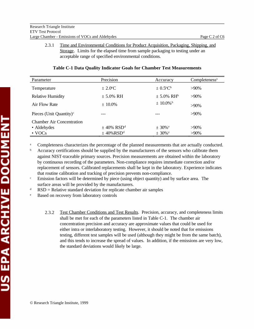
2.3.1 Time and Environmental Conditions for Product Acquisition, Packaging, Shipping, and Storage. Limits for the elapsed time from sample packaging to testing under an acceptable range of specified environmental conditions.
Table C-1 Data Quality Indicator Goals for Chamber Test Measurements
Parameter Precision Accuracy Completenessa
Temperature – 2.0oC – 0.5oCb >90%
Relative Humidity – 5.0% RH – 5.0% RHb >90%
Air Flow Rate – 10.0% – 10.0%b >90%
Pieces (Unit Quantity)c --- --- >90%
Chamber Air Concentration • Aldehydes – 40% RSDd – 30%e >90% • VOCs – 40%RSDd – 30%e >90%
a Completeness characterizes the percentage of the planned measurements that are actually conducted. b Accuracy certifications should be supplied by the manufacturers of the sensors who calibrate them
against NIST-traceable primary sources. Precision measurements are obtained within the laboratory by continuous recording of the parameters. Non-compliance requires immediate correction and/or replacement of sensors. Calibrated replacements shall be kept in the laboratory. Experience indicates that routine calibration and tracking of precision prevents non-compliance. Emission factors will be determined by piece (using object quantity) and by surface area. The surface areas will be provided by the manufacturers.
d RSD = Relative standard deviation for replicate chamber air samples e Based on recovery from laboratory controls
2.3.2 Test Chamber Conditions and Test Results. Precision, accuracy, and completeness limits shall be met for each of the parameters listed in Table C-1. The chamber air concentration precision and accuracy are approximate values that could be used for either intra or interlaboratory testing. However, it should be noted that for emissions testing, different test samples will be used (although they might be from the same batch), and this tends to increase the spread of values. In addition, if the emissions are very low, the standard deviations would likely be large.
© Research Triangle Institute, 1999

Research Triangle Institute ETV Test Protocol Large Chamber - Emissions of VOCs and Aldehydes Page C 3 of C6
2.3.3 Record Keeping and Logs. Various logging requirements shall be implemented for all test parameters, including chamber and analytical performance. Many of these are identified in ASTM D5116-90. Additionally, personnel conducting each procedure shall be so noted. Records of the devices used, date and time of tests, and the test results shall be part of the QA/QC recording process. The completeness of records indicates the care and attention given the QC process.
2.3.4 Sample Management and Custody. Procedures for labeling and tracking product samples, as well as chamber air samples, shall be described. Chain of custody documents shall be used to document all product and sample transfers and operations. A sample custodian shall be designated.
2.4 Quality Control Procedures
QC procedures and acceptance criteria are summarized in Table C-2. All procedures shall be evaluated for acceptable performance at the point the data are generated. This minimizes the need to repeat testing because of out of control situations.
2.5 Control Charts
QC charts will allow visual analysis of system performance and observation of anomalistic or unacceptable deviations. This may be done by use of the Shewart Chart (reference: Shewart, W.A., 1931, Economic Control of Quality of Manufactured Products, Bell Telephone Laboratories). (Cf. ‘Manual on Presentation of Data and Control Chart Analysis’, 6th ed., prepared by Committee E-11 on Quality and Statistics, ASTM, 1991.)
2.6 Internal Performance and System Audits
All major components of the test shall be audited at least once, by the QA Officer. These may include, but not be limited to, the preparation of samples, laboratory systems, analytical measurement systems, data entry, and processing.
2.7 Corrective Action
The need for corrective action may be identified through reviews, internal QC checks, audits or observations made during routine sampling, and analysis activities by project staff. All corrective actions will be documented. No further work may be performed until the problem has been satisfactorily resolved, and the QA Officer has acknowledged approval.
2.8 Quality Assurance Reporting
All data reported on this project shall be accompanied by the applicable QA/QC data, including the results of internal QC checks, audit results, and any necessary corrective actions. The QA Officer will maintain current records of all QA/QC activities.
© Research Triangle Institute, 1999

Research Triangle Institute ETV Test Protocol Large Chamber - Emissions of VOCs and Aldehydes Page C 4 of C6
3.0 STANDARD OPERATING PROCEDURES
The laboratory shall prepare SOPs for all aspects of the analytical procedures. The SOPs shall be specific and be readily available to those involved in the analysis and testing. A copy of the method shall be retained in the laboratory. The SOPs shall address:
• Assembly, calibration, and operation of the sampling system; • Preparation, handling, and storage of the sorbent collection media; • Description and operation of the instrumentation systems, including the sampling device, sample
introduction system, separation chemistry, and data system; and • All aspects of data recording and processing.
TABLE C-2. QC Procedures for Emissions Testing
Chamber Tests Procedure Acceptance Criteria Chamber Tests · Air exchange rate measured during each test · .9 to 1.1 Air changes per hour (ACH) · Temperature measured continuously over test · 21 to 25oC
period · Relative humidity measured continuously over · 45 to 55%
test period · Mixing measured with and without test object · Within 5% of theoretical well mixed model
in place (see Appendix B.2.5) · Chamber spiked with toluene (10 µg/m3) and · % Recovery - 70 to 130%
formaldehyde (0.05 ppm) · Recovery tests conducted prior to any
emissions tests; annually thereafter
Measurement of Chamber Air Concentrations VOCs · Analysis of 10% blank cartridges prior to · <10 ng/cartridge for individual VOCs;
tests <50 ng/cartridge TVOC. · Pump flow rate measured at beginning and · Less than 10% deviation in measured flow
end of sample collection period rate · Chamber air samples collected and analyzed · %RSD £ 40%
in duplicate equal to 10% of chamber air samples
· Laboratory blanks (unexposed cartridges · <10 ng/cartridge for individual VOCs; prepared, stored, and analyzed with samples) <50 ng/cartridge TVOC number analyzed equal to 10% of chamber air sample
© Research Triangle Institute, 1999

Research Triangle Institute ETV Test Protocol Large Chamber - Emissions of VOCs and Aldehydes Page C 5 of C6
Chamber Tests Procedure Acceptance Criteria · Laboratory controls (prepared, stored, and
analyzed with samples); number analyzed equal to 10% chamber air samples
· MDL determinations (cartridges spiked at 5 to 10 ng of target compounds); seven replicates prepared and analyzed; MDL based on measurement variability
· MDL checks
· Sample analysis · Multipoint calibration
· Mid-point calibration check run at the start of every day
· Samples
Aldehydes · Analysis of 3 blank cartridges per batch of 50
cartridges · Pump flow rate measured at beginning and
end of sample collection period · Chamber air samples collected and analyzed
in duplicate equal to 10% of chamber air samples
· Laboratory blanks (unexposed cartridges prepared, stored, and analyzed with samples) analyzed equal to 10% of chamber air sample
· Laboratory controls (cartridges spiked at ~500 ng for target aldehydes then prepared, stored, and analyzed with samples) analyzed equal to 10% chamber air samples
· % Recovery - 70 to 130%
· 2 µg/m3–
· Signal to noise ratio >10 to 1 for analytes on lowest standard
· ·
·
· · ·
·
%RSD of external standard peak <20% %RSD of mean RRF <25% for target compounds Peak width for target compounds, <10 seconds at 10% height
Calculated RRF must be within 25% of average RRF from calibration– External standard peak area within 50% of average from calibration Weak width for toluene, n-decane, cyclohexane, 1-hexanol, <10 seconds at 10% height External standard peak area within 25% of average from calibration
· Less than 50 ng/cartridge of formaldehyde
·
·
Less than 10% deviation in measured flow rate % RSD £ 40%
· Less than 50 ng/cartridge of formaldehyde
· % Recovery 70 to 130%
© Research Triangle Institute, 1999

Research Triangle Institute ETV Test Protocol Large Chamber - Emissions of VOCs and Aldehydes Page C 6 of C6
Chamber Test Procedures Acceptance Criteria · MDL determinations cartridges spiked at 100 · 0.005 ppm
ng of formaldehyde · MDL checks · Sample analysis
· Multipoint calibration · R2 Value ‡ 0.995 · Measured concentration in standard - 85 to
115% of known value · Mid-point calibration check every 8 hours · Measured concentration in standard - 85 to
of analysis 115% of known value
© Research Triangle Institute, 1999


![Document Corel Office [PFP#730745865] - cforp](https://img.pdfslide.net/doc/110x75/6204e9ea4c89d3190e0c76c5/document-corel-office-pfp730745865-cforp.jpg)


![Document Corel Office [PFP#822378741]](https://img.pdfslide.net/doc/110x75/62b42d77320807678d3522c7/document-corel-office-pfp822378741.jpg)


![Corel Office Document [PFP#551583176]](https://img.pdfslide.net/doc/110x75/586906181a28ab847d8b9ad5/corel-office-document-pfp551583176.jpg)

