Embed Size (px)
Citation preview

f
r
i
SO CO 70 Q
1^ )
THEMYOTRON-- A SERVO-CONTROLLED EXOSKELETON
FOR THE MEASUREMENT OF MUSCULAR KINETICS
INTERNAL RESEARCH PROJECT 86-198
FINAL TECHNICAL REPORT
CAL REPORT NO. VO 2401 El
MAY 1, 1968
CORNELL AERONAUTICAL LABORATORY, INC OF CORNEL'. UNIVERSITY. BUFFALO. NY 14221

CORNELL AERONAUTICAL LABORATORY, INC BUFFALO, NEW YORK 14221
• FINAL TECHNICAL REPORT, •
\f THEMYOTRON-
A SERVO-CONTROLLED EXOSKELETON
FOR THE MEASUREMENT
OF MUSCULAR KINETICS *
J.C X 'w
«ETERNAL RESEARCH FROJECT 86-198
Ü/L CAL •••••».-7O-2401-E 1 )
/ MAY t. »68 jbt
L
Prepared By: ^~TK^- J.S. Millar Project Engineer
Approved a
By: 3^~- a>J&+* F.A. Giori, Head Biomedical Electronics Section
{&/*' C.W. Miller, —*"' Electronics Research Department
2nd Printing - Afuv 29, 196S
%/i/j [d +/1

I I t F
ABSTRACT
The Myotron is a new type of instrument for the dynamic measurement
of skeletal muscle forces and behavior. It is basically a servo-controlled
exoskeleton with integral force and position transducers (non-myoelectric).
A two-axis instrument was designed and fabricated to establish the practicality
and medical utility of such a device. In-hospital evaluation of the instrument
as a medical research aid substantiated that the device is potentially suited for
basic studies of neuromuscular activity, studies of neuromuscular disorders,
development of new rehabilitation therapy techniques, and studies of new
powered orthotic devices. This research program (VO-2401-E) was sponsored
internally by CorneU^efonautical Laboratory (authorization 86-198). Medical
orientation an^evaluation assistance was provided by members of the research
staff aCthe Veterans Administration Hospital, Buffalo, N. Y.
—v This report introduces the Myotron concept and describes the construction
and operational principles of the two-axis instrument. The evaluation ex-
periments and results are presented, with recommendations for further
research. A selected bibliography is appended.
\
- ...-..•>: • • - :-

I I r T
I I !
I I I
ACKNOWLEDGMENTS
The potential benefits of applying the man-amplifier principle to a
device for performing medical research were confirmed during discussions
between CAL engineers and members of the Veterans Administration
Hospital research staff and their consultants. Principal among the contrib-
utors were Saul Machover, M. D. , then head of the Physical Medicine and
Rehabilitation Department, William Walsh, M. D. , a research associate in
the department and Beverly Bishop, Ph.D. , Assistant Professor of
Physiology at the State University of New York at Buffalo.
During the development and evaluation phase of the project, continuing
encouragement was received from the aforementioned, and assistance and
working space was provided by the statt of the Department of Physical
Medicine and Rehabilitation, under the acting direction of G. H. Coffey, M. D. ,
in particular Dr. Walsh and Richard M. Johnston, a Research Technician
Physical Therapist.
We are pleased to take this occasion to acknowledge their contributions
to this program.
11

I I
CONTENTS
Section Page
ABSTRACT i
ACKNOWLEDGEMENTS ii
1 INTRODUCTION AND SUMMARY 1
2 MYOTRON DESCRIPTION 4
A. General Description 4
B. Physical Description of Major Components . 4
C. Operating Principles 11
D. Operating Controls and Indicators 14
E. Circuit Design Highlights 21
3 PERFORMANCE EVALUATION EXPERIMENTS 23
A. General 23
B. Subject Attachment and Fixation 24
C. Evaluation of the Servo Control and Logic Functions . . 27
D. Evaluation of Experiment Procedure 29
4 CONCLUSIONS AND RECOMMENDATIONS 4 5
5 SELECTED BIBLIOGRAPHY 48
i
i i in

1. INTRODUCTION AND SUMMARY
This report describes the activity and presents the findings of the
Cornell Aeronautical Laboratory, Inc. (CAL) internal research project
ELBOW, for the development and evaluation of a servo-controlJed exo-
skeleton for the measurement of muscular kinetics. The name "Myotron"
was arrived at for this class of device by combining "myo" for "muscle"
with "tron" for "electronic instrument". A two-axis Myotron for examining
the upper-extremities was designed and constructed to determine the
feasibility and utility of this type of instrument, and was evaluated experi-
mentally at the Veterans Administration Hospital in Buffalo. The staff and
consultants of the VA Hospital provided medical orientation during both
the design and evaluation phases of the program.
Previous research at this Laboratory had studied the problem of
amplifying man's natural strength, via an external mechanized structure, in
order to permit a person with average strength capability to perform very
heavy work tasks with ease. A jointed mechanical body framework, an
"exoskeleton", was designed and instrumented to study the structure necessary
for such a man-amplifier, and a powered exoskeieton design was completed.
Control of the exoskeieton entirely by mechanical force sensors external to
the human body was a basic design criteria, thereby avoiding the need for
myo-electric control contacts to or under the skin. The concept of a
low-power version of man-amplifier emerged from these studies as a
* potentially useful medical research aid in the field of physical medicine and
« rehabilitation. Informal discussions with VA Hospital physiatrists confirmed
I the potential benefits and usefulness of such a research tool.
I Thus, in February 1967, Project ELBOW was initiated to design and
construct a two-axis powered exoskeieton as a working feasibility model of
this medical research-aid concept. The arm was chosen as the limb ior
study, because the human arm motions are simple in nature, but orecisely
controlled by complex neuromuscular control processes and would, therefore,
jj potentially yield the most significant medical results. Furthermore, a num.ber
of previous neuromuscular studies have considered elbow flexion, and coui-
1 parison with these early studies was desirable. Elbow flexion-extension and
" 1
pi»»->i^^-«-"- '--
m-M
I I I I
I
shoulder rotation were chosen as the two axes of movement, thus encompassing
both a group of basic limb muscles and a group of basic trunk muscles. (The
mechanical structure was devised, however, so that knee flexion and hip
rotation could be studied as well.) The b?.sic drive mechanisms and the force
measuring transducers were designed to match the strsngth ability of a normal
man's arm and shoulder. A magnetic tape recorder was incorporated to
record the measurements, as well as to playback programmed motion
sequences for studies of new therapy techniques. Precision analog computer
logic and control circuits were designed to enable the servo-mechanisms to
be operated in a variety of modes for experiment flexibility and accuracy.
Three levels of safety devices were incorporated to minimize the possibility
of potentially harmful motions. Fabrication and check-out of the two-axis
Myotron was completed in December of 1967.
With the cooperation and medical guidance of the Research Staff of the
Physical Medicine and Rehabilitation Department at the VA Hospital, a three-
month evaluation of the medical utility of the device was performed. The
evaluation was divided into three phases:
1. A study and final adjustment of the subject attachment fittings
at the wrist and upper arm, and subject body fixation methods.
2. A study of the control and logic functions under actual test
conditions, and
3. A design and study of three separate experimental procedures
for the measurement of muscular behavior in hemiplegics.
The results of the evaluation experiments indicate that the Myotron is
a powerful new instrument for research in the study of neuromuscular behavior
and disorders and that the present two-axis Myotron will be directly useful
in three principal areas:
1. measurement of muscular forces under controlled dynamic
conditions for basic studies of flaccid and spastic paralysis,
2. study of new therapy techniques, particularly in the management
of spasticity, and
3. evaluation of the man-machine interface problems to be encountered
with force-following powered orthotic devices.
2

I I I
The remainder of this report contains three major sections. Section 2
describes the physical and electrical units and operating principles of the
two-axis Myotron. Section 3 describes the evaluation experiments and their
results. Conclusions and recommendations for future investigations are
presented in Section 4.
i i
i i

I I I
I
I I I
2. MYOTRON DESCRIPTION
A. GENERAL DESCRIPTION
The Myotron is a servo-controlled exoskeleton for the measurement of
external forces produced by skeletal muscles under controlled dynamic
conditions. A two-axis Myotron was designed and constructed to investigate
the utility of such a device as a medical research aid for the study of
neuromuscular disorders and as a potential diagnostic or therapeutic aid.
The two-axis Myotron, with the control and recording console, is shown
in Figure 1. As presently configured, the device is essentially a powered
exoskeleton structure fitted to the human arm, powered to operate in elbow
flexion-extension and shoulder rotation while measuring the related muscular
lorces and limb positions. An earlier unpowered tull-body exoskeleton, with
thirty-three instrumented joints is shown in Figure 2. This structure has
electrical potentiometers at each joint for measurement of position, but the
joints are neither controlled nor restrained and force measuring transducers
are not employed. The same basiic joint construction techniques were amployed
on the two-axis powered unit, Figure 3, with the mechanical members de-
signed to withstand the mechanical loads capable of being generated by a
subject with normal muscular strength.
B. PHYSICAL DESCRIPTION OF THE MAJOR COMPONENTS
The present Myotron is physically composed of three units: the mechanical
arm assembly, a support and equipment table, and a portable control console
and recorder unit. The arm is securely mounted to the support table, but is
adjustable in position to accommodate either right or left arm and any abduction
or flexion angle of the shoulder. The i*ro drive motors are located under the
table, and are coupled to the arm drive mechanisms by flexible shafts. The
drive components of the arm are shown disassembled in Figure 4. The servo
motors and gears, as presently configured, are capable of operation in any
120 degree sector of shoulder rotation, or in any 120 degree sector of elbow
flexion (flexion angles greater than 135 degrees anatomical are not allowed
due to mechanical interference). The motors can drive both axes at any
desired rate up to 100 degrees per second, and can witnstand or produce

AM
I I I
i I !
8 o
©
a. o a 5
1
0)
3
I

3k I I I
t I I I I
Figure 2 UNPOWERED FULL-BODY EXOSKELETON
i

I
I i
s
3 Öl
I

I I I I r
z
a I oo CO 1 o
e
I 1 I
I I I r
i
i
i
i
approximately 50 ft-lb of torque.
The subject's arm is inserted into the metai cuff-like supports at the
wrist and upper arm. The wrist is secured in the support by a split ring
plaster cast. Individual casts are moulded for each subject and serve to
distribute the load forces over the wrist surface without discomfort at the
wrist protrusions. The cast is inserted into a roller-bearing sleeve ring
which allows free rotation (supination-pronation) movement, or the ring may
be locked in a fixed position. The upper arm is supported inside the shoulder
drive ring sleeve by an inflated cuff which secures the arm, but permits arm
volume changes due to muscle contractions.
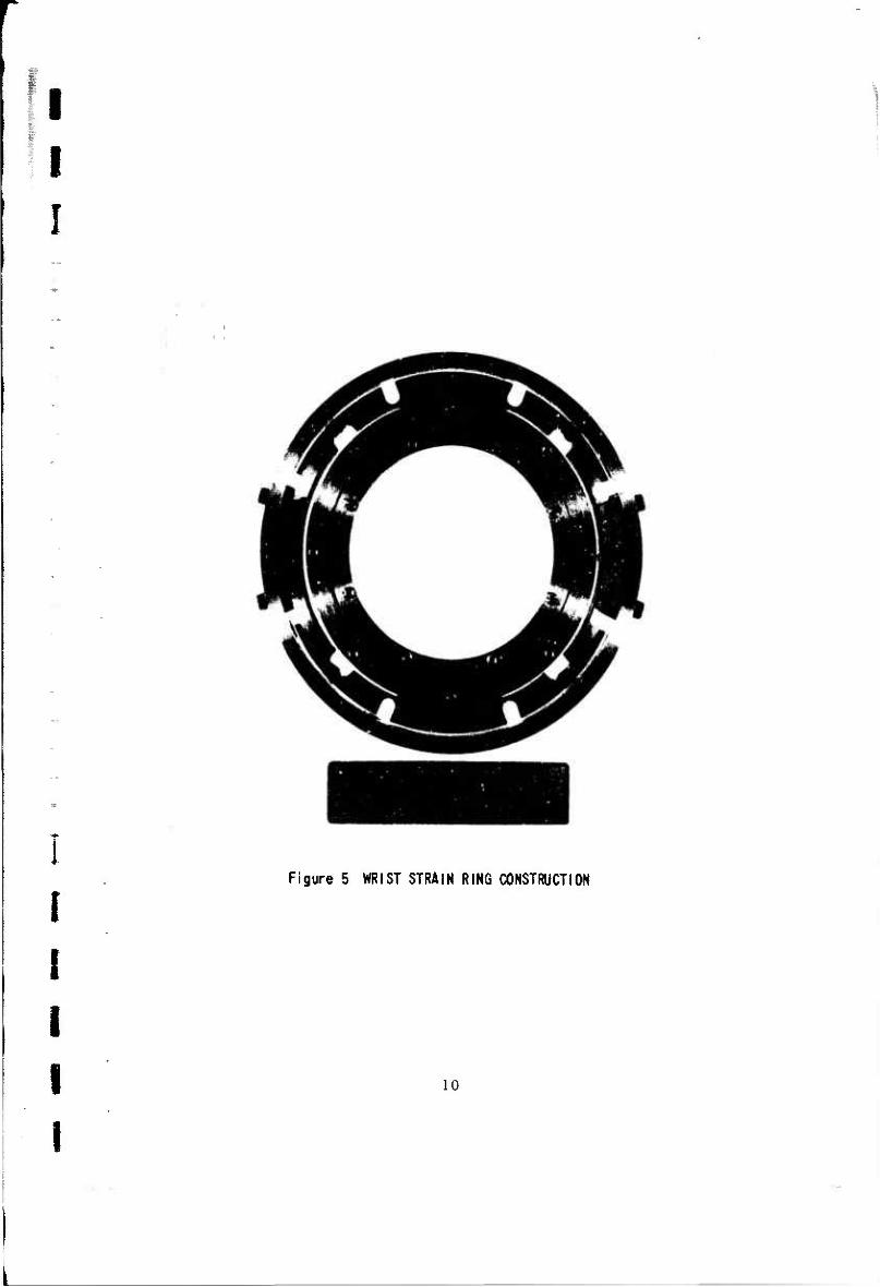
A force exerted by the subject's forearm against the Myotron structure
is measured mechanically as a vector force at the wrist and converted into electrical signals proportional to this force. A strain-gauge ring, Figure 5,
resolves the vector force into two orthogonal components, a flexion-extension
component and a rotation component (the rotation component being geometrically
aligned for shoulder rotation with the arm flexed to the anatomical 90 degree
position). The strain ring is presently capable of resolving force changes of
less than 0.03 pounds while measuring forces as great as 100 pounds. The
ring contains two sets of four strain gauges, arranged in bridge fashion such
that supination-pronation torques and thrust forces do not appreciably affect
the desired force measurements.
The arm support table, in addition to providing a solid base for mounting
the arm, also houses some of the electrical equipment. The drive servomotors,
the high-power servo drive amplifiers and the servomotor power supply are
one common equipment group located on a shelf under the table. The strain
gauge excitation generator and output preamplifiers are also mounted under
the table. Electrical outlets and shelf space are provided for auxiliary ex-
periment equipment such as function generators, oscilloscopes, and emg units.
The portable control console and recorder unit, shown in Figure 1, permits
remote control of all the equipment functions from whatever vantage point is
Force ie the actual measured quantity, and may be converted to torque about the elbow by multiplying the force by the distance of the strain ring from the elbow, which is approximately 10 inches, but varies with each subject.
I I
I I I I I
Figure 5 WRIST STRAIN RING CONSTRUCTION
10

I I
I i i 1 I
desired by the experimenter. The F-M recording equipment is mounted on a
hinged panel at the front of the unit, the controls are located on a sloping
console, and the analog computer logic and control circuits are mounted on
circuit boards under the control console. A low voltage DC power supply is
located behind the recorder panel. Special remote cables are provided to
permit the console unit to operate independently of the arm and arm support
table for playback of a recorded experiment at any remote location.
C. OPERATING PRINCIPLES
The two powered axes, flexion-extension and rotation, are completely
independent in operation, with dual control and measurement instrumentation.
Either axis may be operated singly or concurrently in the same or different
modes.
All motions of the Myotron are controlled by precision servomechanisms
for accuracy and flexibility in performing the experiments. Since both of the
basic output parameters, position and force, are measured as electrical signals,
either may serve as an input to the servo control circuits, resulting in two
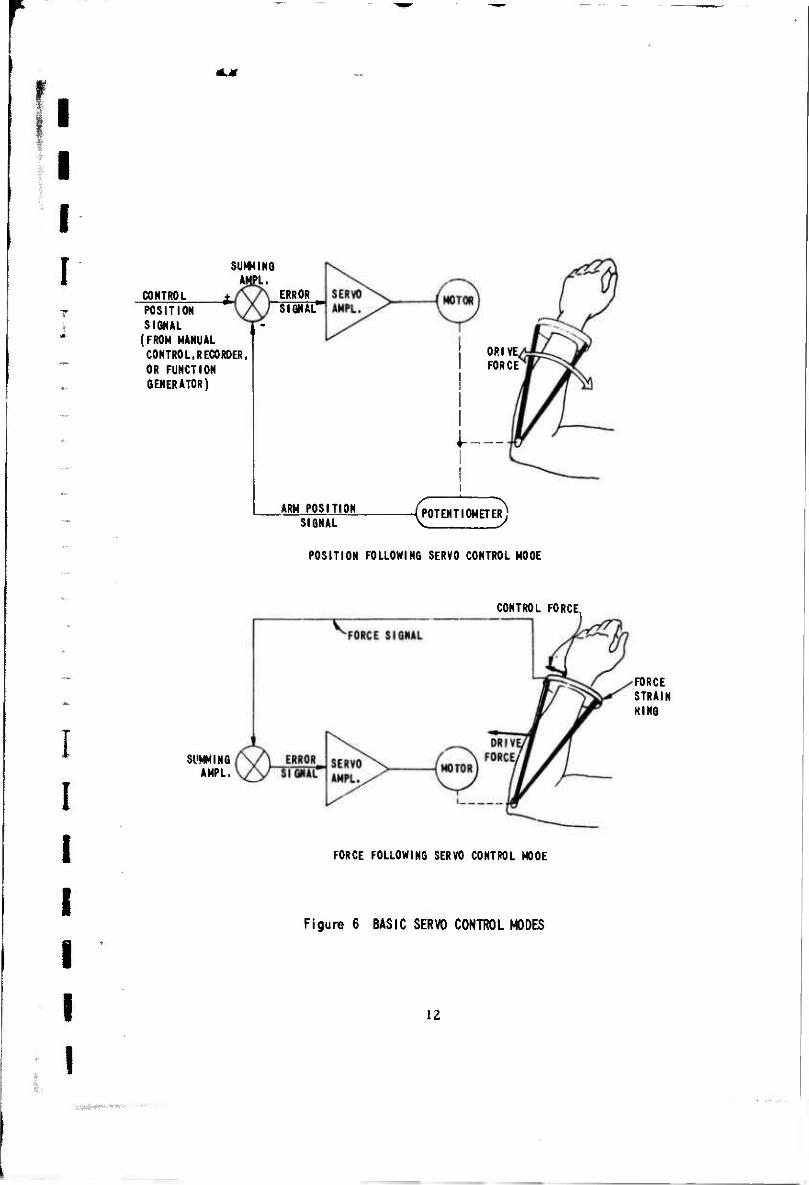
basic modes of operation. Figure 6 shows the functional block diagrams for
these two basic servo control modes: position-following and force-following.
(Only the flexion-extension axis is shown; the rotation axis control is identical.)
In the position-following servo control mode, the desired arm position is
represented as a d-c voltage control position signal, applied as one input to a
summing amplifier. The actual arm position is also represented as a d-c
voltage position signal, and is applied as the other input of the summing
amplifier, with a sign reversal. Therefore, the output of the summing
amplifier is the algebraic difference between the two position signals, or
the error signal. The error signal is amplified and used to drive the servomotor
in the direction necessary to cause the arm position to match the desired
position. When the arm position exactly matches the desired position, the error
signal is zero, and the servomotor drive signal is zero. The desired position
signal may he derived from the position control lever on the control console,
from a position signal pre-recorded on magnetic tape, or from an external
voltage source with a scale factor of 12 degrees per volt. This external
source typically would be a function generator to cause the arm position to
follow a specific function such as a sine-wave or triangular wave. The basic
11
*.*
I I I r SUMMING
AMPL.
CONTROL POSITION SIGNAL
(FROH MANUAL CONTROL, RECORDER, OR FUNCTION GENERATOR)
ERROR SIGNAL*
ARM POSITION
DRIVE. FORCE
I—
SIGNAL i POTENTIOMETER)
POSITION FOLLOWING SERVO CONTROL MODE
CONTROL FORCE,
I I I I I l
SUMMING AMPL.
FORCE FOLLOWING SERVO CONTROL MODE
Figure 6 BASIC SERVO CONTROL MODES
FORCE STRAIN KING
12

I I F
i I I I I
static position accuracy, due to combined system tolerances, is approximately
+ 0.5 degrees. The principal dynamic error, proportional to velocity, is less
than 2.5 degrees at the maximum speed of 100 degrees per seconds However,
if the input command signal exceeds this velocity, or the velocity limit setting
on the control console, the position lag will increase accordingly. In general,
this mode of operation is used for experiments which measure forces as a
function of position.
The operation of the Myotron in the force »following mode is analogous
from an electrical standpoint. Any force exerted by the subject's arm
against the strain ring results in a d-c voltage proportional to the magnitude
and direction to the applied force. In this mode, the servomechanism acts
as a nulling device, driving the mechanical arm in the direction necessary
to reduce or null the applied force. This is accomplished by applying only
the d-c force signal to the summing amplifier. Therefore, the servomotor
will respond to any detectable force signal. (The most sensitive gain control
setting results in arm movement for force levels grceater than about 0.03
pound.) Thus when the subject attempts to, say, raise his arm, the force
detected as the muscles contract cause the motor to raise the mechanical
arm. or to follow the force exerted by the subject. The servomotors will be
driven to their maximum velocity for very slight applied forces, so that the
arm will follow attempted motions with little effort by the subject. However,
if the maximum speed limit (100 degrees per second, or front panel control
setting) is exceeded , a marked increase in force will, of course, be measured,
Using analog computer logic techniques, variations may be imposed on
this basic force-following mode. The simple addition of a d-c voltage to the
summing amplifier results in the addition of a spiing-like force to the servo
loop. For the system to null, the subjects arm must exert a force to counter
the added force, giving the "feel" of pulling against a spring. This voltage
counterforce is adjustable in magnitude and direction with a front panel
control.
Another logic circuit operation is used to employ a force threshold,
whereby the mechanical arm will not follow the intended motion until the
force exerted by the subject exceeds some threshold force. This has the
13
I I !
I I J I I I
effect of adding a resistance to movement, similar to that produced by a
slipping clutch, requiring considerable work to reposition the arm. This is
accomplished by adding a threshold circuit to the error signal jjath, requiring
that the error signal exceeds the selected threshold to activate the servo
amplifier. This threshold level is also selectable with a front panel control.
The simultaneous addition of a counterforce signal acts to bias the
threshold, enabling motion in one direction with less resistance than in the
opposite direction. In general, the force-following mode of operation is
used for experiments which measure position change as a function of force,
such as active range of motion studies.
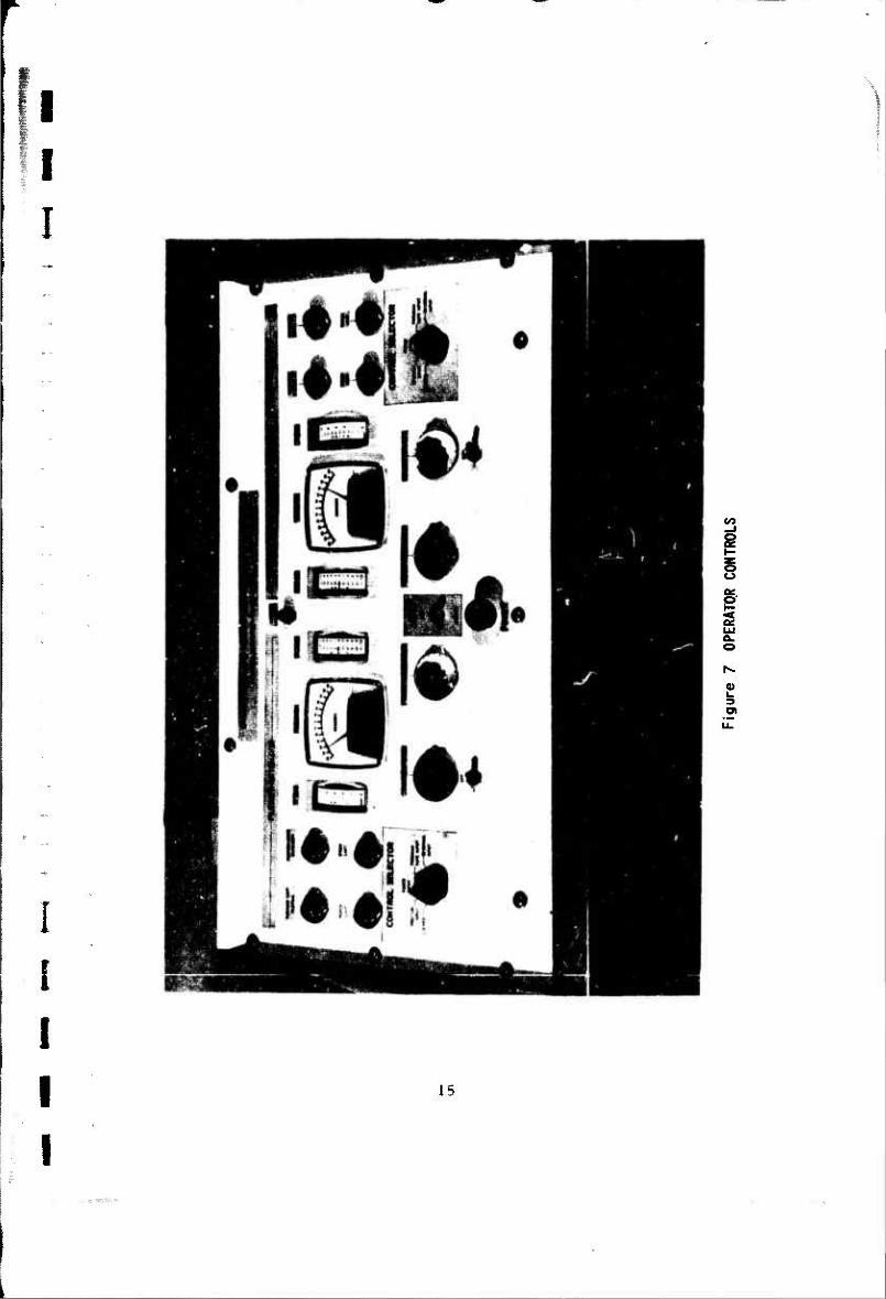
D. OPERATING CONTROLS AND INDICATORS
The controls on the operator console may be functionally divided into
two categories: those common to both axes, and those for individual axis
control. The individual controls are arranged in three groups: the meters,
the operating controls and the safety limit controls. Figure 7 shows the
locations of these controls on the operator console.
The controls common to both rotation and flexion-extension axes are
listed below.
1. The POWER switch is an illuminated push-on, push-off switch
which controls the input 115 VAC power from the line. It is
arranged to function as an emergency stop switch, for the motors
will brake to a halt within a tenth of a second after the operator
pushes this centrally-located, large switch.
2. The RECORD indicator is an amber light indicating that the
recorder operating controls are in the record position, and
is intended as an operator warning to prevent inadvertent
recording on a pre-recorded tape intended for programmed motions,
3. The REMOTE POSITION CONTROL LEVER, located on the side
of the control console (s°e Figure 1) is a gimhal control to
simulate and control the possible positions cf the arm in flexion-
extension and rotation. This control is active only with the
control selector switch set to POSITION INPUT.
14
I I
I !
I I
s
s
tu 3
15
I
I I I T
I I
The controls for the individual flexion-extension and rotation axis
are symmetrically arranged on the left and right side of the console. The
meter group is listed below.
1. The POSITION meter indicates the arm position in degrees
with respect to an arbitrary zero position (normally the center
of the possible range of arm travel). Full scale on the meter
is +_ 60 degrees.
2. The FORCE meter indicates the force exerted on the strain
ring in the direction of axis travel. Full scale deflection is
adjustable with the FORCE SENSITIVITY control for any level
between three and one hundred pounds. (The single toggle
switch sensitivity control shown in Figure 7 was replaced with
two individual-axis continuous dial controls for greater
flexibility.)
3. The SPEED meter indicates the speed of arm movement in
degrees per second, with 100 degrees per second being full
scale deflection.
The individual axis operating controls are listed below.
1. The CONTROL SELECTOR switch may be positioned for the
following operating modes,
— LOCKED - The arm remains locked in the present
position.
— POSITION INPUT - The arm follows the position of
the remote position control lever.
— FORCE INPUT - The arm is controlled by the force
exerted at the strain ring, and the settings of the
counterforce and rorce threshold controls.
— PROGRAM TAPE INPUT - The arm follows the position
programmed on the tape recorder. (Recorder
preamplifiers must be in the playback mode.)
16

r i
i
— EXTERNAL INPUT - The arm follows the position
command of the d-c voltage applied to the external
input jack, zero volts for center position, 12 degrees
per volt sensitivity.
2. The COUNTERFORCE control dial and selector switch
determine the level and direction of a constant "spring"
force added to the force-following control mode. The dial
is calibrated in percent of full scale of the force meter, and
the counterforce is indicated on the force meter in summation
with the force applied at the strain ring. The center position
of the toggle switch is zero counterforce.
3. The FORCE THRESHOLD control dial setting determines
the amount of force necessary at the strain ring for the arm
to operate in the force-following mode. This is equivalent
to a constant "resistance" force. The dial is calibrated in
percent of full scale of the force meter.
The safety controls on the front panel are electronic limits for
position, speed, and force. These limits are in operation regardless of the control mode selected, and will override any control input signals.
Their operation is described below.
1. The two POSITION LIMIT control dial settings determine the
maximum, arm excursion from the zero degree indication
on the position meter. They are individually adjustable
for different plus or minus directions, and are calibrated
in percent of maximum deflection (60 degrees).
2. The FORCE LIMIT control dial setting indicates the maximum
force level attainable while the motors are activated. If
that force level is reached, the motor will drive the arm in
the proper direction necessary to reduce that force. The
dial is calibrated in percent of full scale of the force meter.
17

«.*
I I f f
I l
3. The SPEED LIMIT control dial setting determines the maximum
speed of the arm for any operation, including any switching
transients. The dial is calibrated in percent of full scale of
the speed meter.
To further protect the subject from unintended and potentially harmful
motions, two other safety controls are incorporated. Adjustable mechanical
limit switches are positioned on the arm itself, and are connected in such a
way that if either the rotation or the flexion-extension angle exceeds the
mechanical limits, the drive servomotors are dynamically braked to a
halt. The motors cannot be operated until the arm is mechanically re-
positioned by manual means to within the prescriood limits. In addition,
the subject may be given a hand-operated switch (shown attached to the
side of the console in Figure 1) which prevents the motors from operating
unless the switch button is depressed. If the subject releases his grip on
this switch, the motors are dynamically braked to a halt. (At the discretion
of the operator, this switch may be bypassed by removing the cable jack from the control console.)
The tape recorder and preamplifier controls are pre-set to calibrated settings, except for the playback-record selector switch on the preamplifier,
and the tape transport selector on the tape recorder. The tape transport
selector combines the stop-plav function with the fast forward and rewind
functions. The tape recorder uses standard 1/4 inch magnetic tape, and
will record for over 45 mimues on one reel. Input and output jacks are
provided for monitoring and strip-chart recorder playback of the four
channels. The channel assignments are (in order from top to bottom
preamplifier) rotation force, flexion extension force, rotation position
and flexion-extension position. The input and output sensitivities are
+ 5 volts full scale, and the overall frequency response including the FM
modulators and demodulators is from, d-c to 3 db down at 60 IIz.
Standard 4-tracktype 87 Viking tape transport with type RP83 preamplifiers,
18
I I
I I
3. The SPEED LIMIT control dial setting determines the maximum
speed of the arm for any operation, including any switching
transients. The dial is calibrated in percent of lull scale of
the speed meter.
To further protect the subject from unintended and potentially harmful
motions, two other safety controls are incorporated. Adjustable mechanical
limit switches are positioned on the arm itself, and are connected in such a
way that if either the rotation or the flexion-extension angle exceeds the
mechanical limits, the drive servomotors are dynamically braked to a
halt. The motors cannot be operated until the arm is mechanically re-
positinned by manual means to within the prescribed limits. In addition,
the subject may be given a hand-operated switch (shown attached to the
side of the console in Figure 1) which prevents the motors from operating
unless the switch button is depressed. If the subject releases his grip on
this switch, the motors are dynamically braked to a halt. (At the discretion
of the ope;ator, this switch may be bypassed by removing the cable jack
from the control console.)
The tape recorder and preamplifier controls are pre-set to calibrated
settings, except for the playback-record selector switch on the preamplifier,
and the tape transport selector on the tape recorder. The tape transport
selector combines the stop-play function with the fast forward and rewind
functions. The tape recorder uses standard 1/4 inch magnetic tape, and
will record for over 45 minutes on one reel. Input and output jacks are
provided for monitoring and strip-chart recorder playback of the four
channels. The channel assignments are (in order from top to bottom,
preamplifier) rotation force, flexion extension force, rotation position
and flexion-extension position. The input and output sensitivities are
+ 5 volts full scale, and the overall frequency response including the FM
modulators and demodulators is from d-c to 3 db down at 60 Hz.
Standard 4-tracktype 87 Viking tape transport with type RP83 preamplifiers
18

I i I I
The playback of data from the tape recorder to a strip chart recorder
or other display device may be arranged in a number of possible formats.
A typical arrangement for a strip chart recorder playback is shown in
Figure 8.
i i I I 19
i

I I f
I
I I I
(INTERNAL)
ROTATION POSITION (degrees)
ROTATION FORCE
(pounds)
FLEXION- EXTENSION
FORCE (pounds)
FLEXION- EXTENSION POSITION (degrees)
NOTE: TEST CONDITIONS — FORCE FOLLOWING SUBJECT'S FLEXION-tXTENSION MOVEMENTS WITH VELOCITY LIMIT IMPOSED AND TWO-HERTZ POSITION DITHER APPLIED TO ROTATION AXIS. (SUBJECT NORMAL)
Figure 8 MEASURED PARAMETERS — TYPICAL PLAYBACK FORMAT
20

I I I I f
•i
I I !
I I I
E. CIRCUIT DESIGN HIGHLIGHTS
The operating concepts described in the previous sections of this
report are functionally simple, and for the most part, were implemented
using standard design techniques. However, a few design areas required
very special, and in some instances, novel implementation methods worthy
of special mention.
The simplified functional block diagrams of Figure 6 show the basic
servo control feedback loops, and indicate that the summing amplifier has
two inputs. The actual circuit has eight active parallel inputs:
1. the desired control signal (selected by the control selector)
2. the feedback control signal (selected by the control selector)
3. a velocity feedback signal for damping
4. a motor current feedback signal
5. the position limit override signal
6. the velocity limit override signal
7. the force limit override signal, and
8. a servo amplifier gain feedback signal.
The majority of these signals are non-linear in nature, and cannot
be readily analyzed using classical feedback theory. However, design
objectives were achieved by designing those circuits to ensure precise,
stable d-c gain characteristics, and frequency responses well in excess
of the frequency response of the basic servo circuits. The basic velocity
feedback signal was derived from the filtered motor armature voltage, and
adjusted for critical damping of basic servo response. Care was taken to
ensure that the same open loop gain was achieved for the two basic operating
modes to maintain the critical damping factor. The gain factors for the
overriding limit functions are necessarily higher, resulting in an under-damped
response, but this is desirable for these "emergency" conditions where re-
sponse time is more important than accuracy. The motor current feedback
is adjusted to permit three times the rated motor current to flow for brief
21

I I r
transient high torque conditions, yet prevent excessive high current under
long term stall conditions. This permits safe but efficient use of a relatively
small motor.
The basic servo amplifier design is also unique, in that the motors
are driven by switching transistors using a pulse-burst width modulation
technique. The motors are 120 volt, 1/8 horsepower d-c continuous-duty
industrial motors. For efficiency in the servo drive amplifiers, a pulse
width modulation scheme was devised whereby switching transistors
could apply full 120 volt pulses to the motor through a filter circuit,
whereby the average voltage across the motor would vary depending upon
the pulse width and motor load. The pulse repetition frequency is a
constant 60Hz. This technique was complicated by the 240 volt (motor
reversal) requirements imposed on the switching transistors. A series
connected transistor circuit using present state-of-the-art 160 volt 10 amp
transistors protected with 140 volt zener diodes was devised in a bridge
arrangement to overcome this problem. To drive the transistors from
the low voltage control circuits, the control pulses were modulated on a
5KHz carrier, and transformer coupled to the power transistors. The
phasing of the 5KHz drive signals and the control pulses were chosen
to eliminate the problem of inadvertent switching on of any but the
appropriate pairs of transistors in the bridge circuit. Therefore the
T actual drive transistors are controlled by the width of a 5KHz pulse burst.
Another design innovation arose to meet the requirements for the
| limit circuits. A circuit was needed that would accept a bipolar d-c signal,
* and yield a linear output only when the input signal level exceeded a
, selected threshold level. A circuit was devised to provide this "electronic
§ backlash" function, by incorporating two constant-current source circuits
to provide balanced back-bias for a pair of series switching diodes. This
| useful circuit was employed as the logic element in all of the limit circuits,
and for the force threshold operation. i | The remainder of the circuit requirements were fulfilled using
standard circuit designs, employing operational amplifiers and micro-
jj logic elements wherever practical. Special care was taken to minimize
the possibility of electrical shock in a hospital environment, by electrically
1 grounding all exposed conducting surfaces to a common ground which is
connected to the building ground.
i 22
3. PERFORMANCE EVALUATION EXPERIMENTS
A. GENERAL
This section of the report describes the experiments which were conducted
to evaluate the performance of the two-axis Myotron, using both normal subjects
and spastic subjects, in a research hospital environment. The purpose of this
effort was not to obtain clinically valid data from the experiments, in the sense
of subjecting a significantly large population to tests defined by a specific
protocol. But rather, the efforts were primarily of a cut-and-try investigative
research nature to determine suitable types of experiments to demonstrate
the experimental utility and flexibility of the device. Any data obtained which
may have medical significance requires further assessment and is not discussed
in this engineering report.
This phase of the program was a team effort: the principal members
being a Physiatrist and a Physical Therapist from the VA Hospital Research
Staff, and the research engineers from the CA L staff, Support was provided
as necessary from a VAH consulting physiologist, the Manual Arts Therapy
Section, and other VAH services, as well as from the CAL technical and
design shop services. As with any new tool, a great deal of learning was
anticipated to be necessary. The medical team members were learning the
operational principles and procedures of the Myotron, and the CAL engineering
participants were learning the practical operational problems encountered
with patients with various disabilities and the medical significance of potential
experiments.
In general, the following practices were observed for each experiment
involving subjects.
1. A physiatrist was present to observe and record the physiological
status of the subject, to determine the safety limits desired, and
- for general consultation and direction
2. The pertinent force and position measurements were calibrated
on the recorder, using known force and position standards.
m
I
I I I
3. The subject's entire body position was carefully adjusted, and was
recorded by polaroid photographs.
23
I I I I I
1
I I
4. The subject's passive maximum range of motion was determined
and the position limits were set to prevent those limits from
being reached.
5. The experiment was performed, maintaining a log of the
activities and time.
6. A post-test calibration was recorded.
7. The recording was played back on a strip chart recorder, and
the recordings marked to identify the date, subject, experiment,
and calibration scale factors.
This set of general experimental guidelines was operationally satisfactory,
and is recommended for future experiments.
B. SUBJECT ATTACHMENT AND FIXATION
The first operational experiments were devised to investigate the various
methods of attaching the Myotron to the subject, and of fixing the body position
of the subject. It was initially planned to use flexible inflatable pressure cuffs
to secure both the wrist and upper arm in place, and simply to have the
subject in a sitting position in a chair or wheel chair. The height of the
Myotron "shoulder" from the floor had been chosen for a tall man in a wheel
chair, intending to raise the chair with shims as necessary for shorter
subjects.
— The initial tests involved explorations of the various modes of operation,
1 and the wrist pressure cuff was shown to be inadequate for any tests requiring
substantial force measurements. The wrist is remarkably free of protective
I muscle or tissue and the air cuff would not act as a sufficient cushion for
protection against the metal strain ring. Also, rather large thrust forces
I are developed involuntarily during certain procedures, and the pressure cuff
would not adequately restrain the wrist from thrust motions.
|| A wooden split-ring cuff v/as devis d, shaped in general to the surface
of an average wrist. The length of the cuff was 2 inches, and this approach
[1 succeeded in di' ributing the forces over sufficient wrist area to allow
maximum force to be exerted without discomfort. However, significant
24
.;: .-. .• •-'•' • >-="•

I I f
I I
variations were found to exist in the shape and sizes of individual wrists, and
a "universal" wooden cuff proved impractical.
This problem was adequately solved by moulding individual wrist casts
for each subject from rapid-setting plaster. The casts were moulded to the
shape of the subjects wrist using a plaster gauze which sets in less than 10
minutes, splitting and removing the cast, and then moulding the outside
diameter with ordinary plaster to conform to a split steel ring which could
be firmly attached to the strain ring. Figure 9 shows a subject fitted with
this type of wrist cast.
A standard blood pressure arm cuff proved adequate to secure the
upper arm within the metal sleeve of the Myotron, however, whenever the
arm was flexed, the elbow joint itself was not well fixed, and could swing
several inches with certain muscle contractions. To help stabilize the elbow,
the inner ring of the Myotron upper arm support was re-fashioned with a
cylindrical leather padded trough, which extended to the elbow along the
location of the triceps muscle. This reduced the amount of elbow swing
to less than one inch.
For the measurement of maximum strength, body fixation was found to
be of primary importance. For example, a typical normal subject could
exert a maximum flexion force (arm fixed at 90 degrees of flexion) of 35
pounds if the body and shoulder muscles were not allowed to be used, and 50
pounds if the use of the body and shoulder muscles was permitted. Furthermore,
the same subject could, under the latter circumstances, withstand an external
extension force of 85 pounds. The primary reason for this variation is due to
an aspect of muscle physiology; that a skeletal muscle is much stronger in
eccentric contraction than in concentric contraction. When this subject attempted
to move the arm in the direction of flexion, actually a concentric contraction,
he registered 35 pounds. When the subject was permitted to use his body and
shoulder muscles, his tendency was to lock the elbow and use his body muscles
to "pull" against the locked arm, putting his elbow stabilizing muscles in
eccentric contraction, increasing his registered force to 50 pounds. Fixing
his entire body against an external force further increased this effect.
£5

I I I
Photograph courtesy of Veterans' Adminis t rat ion Hospital, Buffalo, New York
!
I
I I I
Figure 9 SUBJECT PLACEMENT SHOWING WRIST CA3T AND UPPER ARM PRESSURE CUFF AND SUPPORT
26

I I I 1
The principal conclusions drawn from this study of body fixation were
that the entire body position, support and restraint were of critical importance
in the absolute measurement of the strength of any muscle group, and that
no one body fixation method would be adequate for the different types of force
measurement possible with the Myotron, Instead, the body fixation method
should be left to the discretion of the experimenter for each particular
experiment. In general, means should be employed to position each subject
in the same repeatable position for a given experiment, perhaps with the
aid of gentle restraint mechanisms. Attempting full restraint of the entire
body would probably so alter the subject's physical and emotional status as
to render any test data questionable.
One minor subject attachment problem arose which is worthy of brief
mention. The carrying angle was not accounted for in the basic flexion
extension axis design. The carrying angle is the natural offset angle between
the upper arm and the forearm, greatest at full extension with the wrist in
the full supination position. This angle varies from 10 to 20 degrees, and is
generally greater in females than ***. males. Accommodation was made for
the effect of this angle, (an internal thrust of the elbow joint when the arm is
fully extended) by flaring the upper arm support trough to provide clearance
for the epicondyle protrusion, which otherwise was a source of discomfort
at full extension.
In summary, adequate attachment and fixation was provided by the use
of the wrist cast, the upper arm inflatable cuff and trough support, and the
use of a sturdy chair to position the subject. Care must be taken to note and
repeat the entire body position and activity of the subject for a given experiment,
i
i i I
C. EVALUATION OF THE SERVO CONTROL AND LOGIC FUNCTIONS
All individual servo control and logic functions were examined under test,
and some changes were incorporated to improve the operational performance
of the Myotron. In general, however, it was found that the basic operating
controls and operating ranges were adequate for the intended experiments.
27
I I I [
In the position-following servo modes, the only difficulty encountered
was with a resonant chatter at certain velocities when the motion was being
aided by a force from the subject. This was caused by a combination of gear
backlash, irreversibility of the worm drive, and spring in the flexible
shafts. This resonance phenomona was eliminated by increasing the inertia
of the worm gears by adding flywheels to the worm gear shafts. These
small flywheels also served as manual positioning knobs for moving the arm
with the power off.
A more basic problem was encountered in the force-following mode of
operation. Basic instability was found to occur in the high sensitivity force-
following operations. The nature of the instability varied with the individual
subject, and was, in general, more severe for subjects with large fleshy
forearms. The basic frequency of the instability was approximately four
or five cycles per second with the forearm and hand muscles relaxed, and
would increase to twelve to fifteen cycles per second with the muscles tensed.
The principal reason for this effect is that in the force-following mode, the
mass of the arm is the controlled element, and the displacement must be
considered with respect to the center of mass, not the center of the bone
structure at the wrist. Since the mechanical arm is tightly coupled to the
bone structure at the wrist, the actual load is connected to the drive through
a varying spring constant determined by the rigidity of the muscles and
flesh.
To avoid this instability in the high sensitivity mode, a 2 Hz low pass
filter ("flab" filter) was inserted into the feedback path of the servo control
loop. This filter does not effect the response of the recorded force signals,
but does prevent the resonant instability from occurring during force-following
operations. The response of the system remains adequate for normal force-
following studies. o
One front panel control was changed to increase the flexibility of the
instrument. The sensitivity of the force meters and controls were originally
determined by a two position switch, allowing for either 100 pounds full scale
sensitivity in the NORMAL position or 5 pounds full scale sensitivity in the
MAXIMUM sensitivity position. This switch control was replaced with a
28
i

I I F pair of continuous dial controls for individual flexion-extension and rotation
sensitivity adjustment at any level from 3 to 100 pounds full scale. The dial
settings read approximately in pounds, and a calibration curve is used for
setting exact sensitivities.
Another minor operational feature was added to enable playback of
recorded experiments at a remote location. A conversion cable was made
to permit the operator console and recorder unit to receive line power and
function normally without being connected to the arm and support table.
This was added :<s a convenience to allow the portable console to be wheeled
to any remote facility for playback of the recorded data on a strip chart
recorder.
The principal conclusion of the evaluation of the servo control and
logic operations is that the Myotron operating principles are basically
sound. Particular attention must be given to the nature of the mechanical
load mass characteristics in a force-following system of this type.
D. EVALUATION OF EXPERIMENT PROCEDURES.
To evaluate the operational effectiveness of the two-axis Myotron, three
simple single-axis experiments were designed for the measurement of certain
spasticity parameters in hemiplegic subjects: static force measurements,
active range of motion measurements, and constant velocity measurements
of relaxed arm residua) forces.
1. Static Force Measurements
To examine the basic operating characteristics of the force
measurement portions of the instrument, an experiment was designed to
obtain maximum force characteristics of the elbcw flexor-extensor muscles
as a function of elbow flexion angle. The arm was positioned to five discrete
flexion angles, starting near maximum extension, and progressing 30, 60,
90 and 120 degrees. At each position, the subject was requested to exert a
maximum force in flexion, holding for 3 seconds. A number of trials, usually
three, were performed, and then repeated in the extension direction, with
suitable rest intervals between trials. The results were plotted as continuous
force versus angle curves, as well as discrete vector forces for each angle
position. ?Q
I
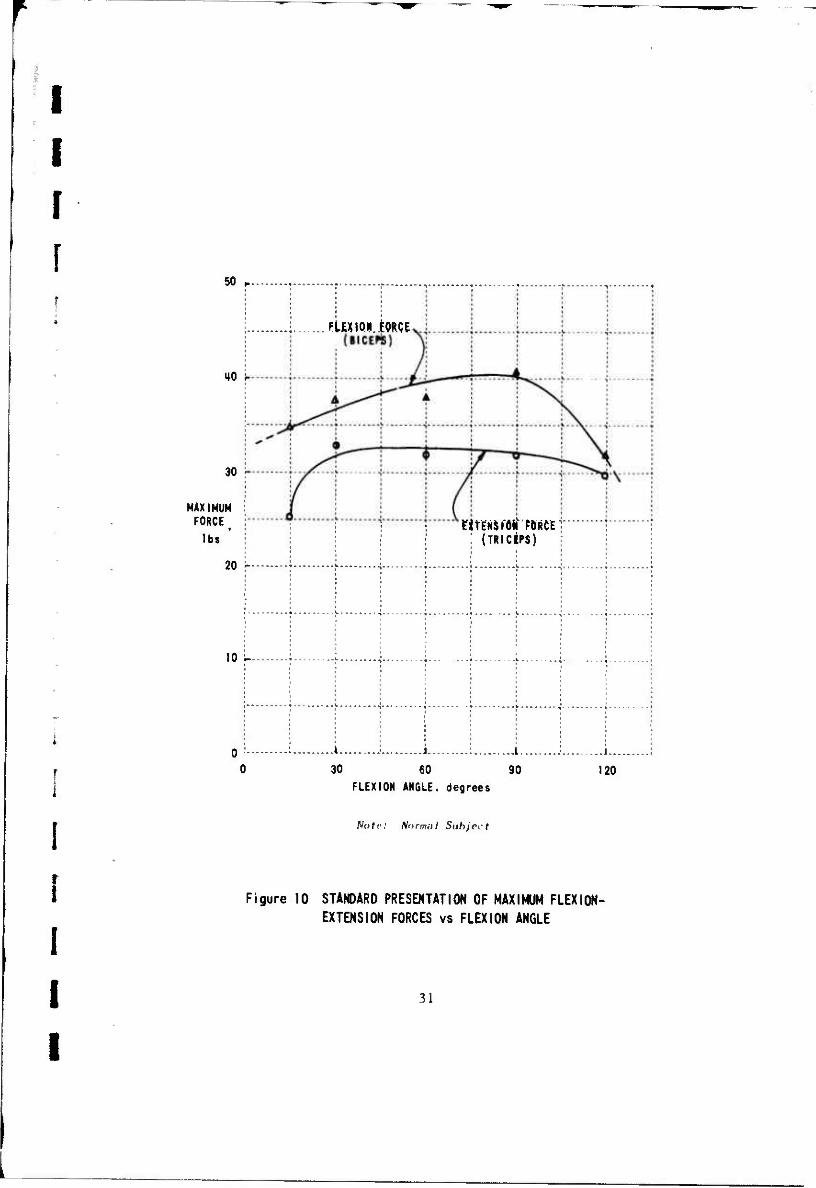
Figure 10 shows the standard method of presenting the measured
data, which accounts only for the force component in the flexion or extension
direction. Figure 11 shows one method of displaying the information as a
vector force. In this instance, the magnitude of the force is indicated by the
magnitude of the vector arrow, and the direction of the force is indicated by
the direction of the vector arrow. The orientation of the polar plot is the
same as viewed when looking at the subject's right hand in line the the forearm.
Figure 12 shows the behavior of the vector forces as a function
of flexion angle for three normal subjects and one hemipiegic subject. Normals
A and C controlled the flexion force direction very accurately, whereas normal
B indicated a marked tendency toward internal rotation as the flexion angle
increased. The hemipiegic subject's force levels were considerably less in
magnitude, consistently favored external rotation during attempts at flexion,
and were completely disoriented in attempts at extension. The diagrams show
that although the subject was attempting to extend, the actual force exerted
was in the flexion direction. The subject could not see the force meters, and
actually thought that he was directing the force in the extension direction. The
residual forces returned to less than two pounds between the force atterrpts.
Figure 13 shows the recorded raw data as played back on a
strip chart recorder. In this form, the time history of the muscle tension is
clearly shown. This subject tended to increase tension rapidly at first, then
slowly approach the maximum, and rapidly relaxed to zero. The residual
force between attempts is principally due to the weight of the subject's arm and
cast. The transients on each trace> indicate that the recorder was stopped
during the rest int.-.rvals between trials.
2. Active Range of Motion Measurements
To examine the utility of the force-following mode of the
instrument, an experiment was devised to measure the unaided active range
of motion in the flexion-extension axis. The shoulder was rotated to the
anatomical zero position, with a 90 degree flexion angle to allow the elbow
flexion-extension motion to sweep over a horizontal plane. This position
30
I I [
[ 50 „.
10
30
MAXIMUM FORCE
lbs
20
10
FIEXIQU.MQE, BICEPJ5'
riTENJJlOtf "FORCE . (TRICiPS)
l j 1 : L.
30 60 90 FLEXION ANGLE, degrees
..1...
120
Note: Normal Subject
Figure 10 STANDARD PRESENTATION OF MAXIMUM FLEXION- EXTENSION FORCES vs FLEXION ANGLE
i i
31

I I [
[ w
vV 90'
X FLEXION ANGLE
I I I
VECTOR FORCE
DIRECTIONS
EXTERNAL
ROTATION*
^
FLEXION
A/.
m WA INTERNAL
ROTATION
60' EXTENSION
FLEXION COMPONENT
EXAMPLE:
SUBJECT ATTEMPTS TO EXERT A MAXIMUM FLEXION FORCE
RESULTS:
FLEXION FORCE = 35 1 bs INT. ROT. FORCE = »5 lbs ACTUAL FORCE = 38 lbs /U*
ACTUAL VECTOR FORCE
ROTATION COMPONENT
30' (50 lbs FULL SCALE)
0°
Figure 11 KEY TO VECTOR FORCE PRESENTATION
32

NORMAL A I NORMAL B 1 | NORMAL C 1 |—HEMIPLEGIC—1
rtvn
///
^m
90'
•MAXIMUM FLEXION
FORCE
MAXIMUM EXTENSION
FORCE
I I I 1
#;im
<ujliv to*
50 lbs FULL SCALE 50 lbs FULL SCALE
w/l. 10°
50 lbs FULL SCALE 10 lbs FULL SCALE
Figure 12 MAXIMUM FLEXION-EXTENSION VECTOR FORCES - 3 NORMAL SUBJECTS, ONE HEMIPLEGIC
i

I I r
i o ©
I I I I I I ! I I ooooooooo CO <N — — N » tf Ifl
ooooo OOOOOO IflSf « N- — CM en =*• m e ° W «0
o o O» CM
I 2 tu £
O "- a.
ÜUJ •» _ c> si
2 l*1 M °» -* 5 o •£ u. **. £ ä
I i i
34
I

I I I r
[
i i i i
i i i
eliminates the force variation due to a changing weight vector as the elbow
is flexed.
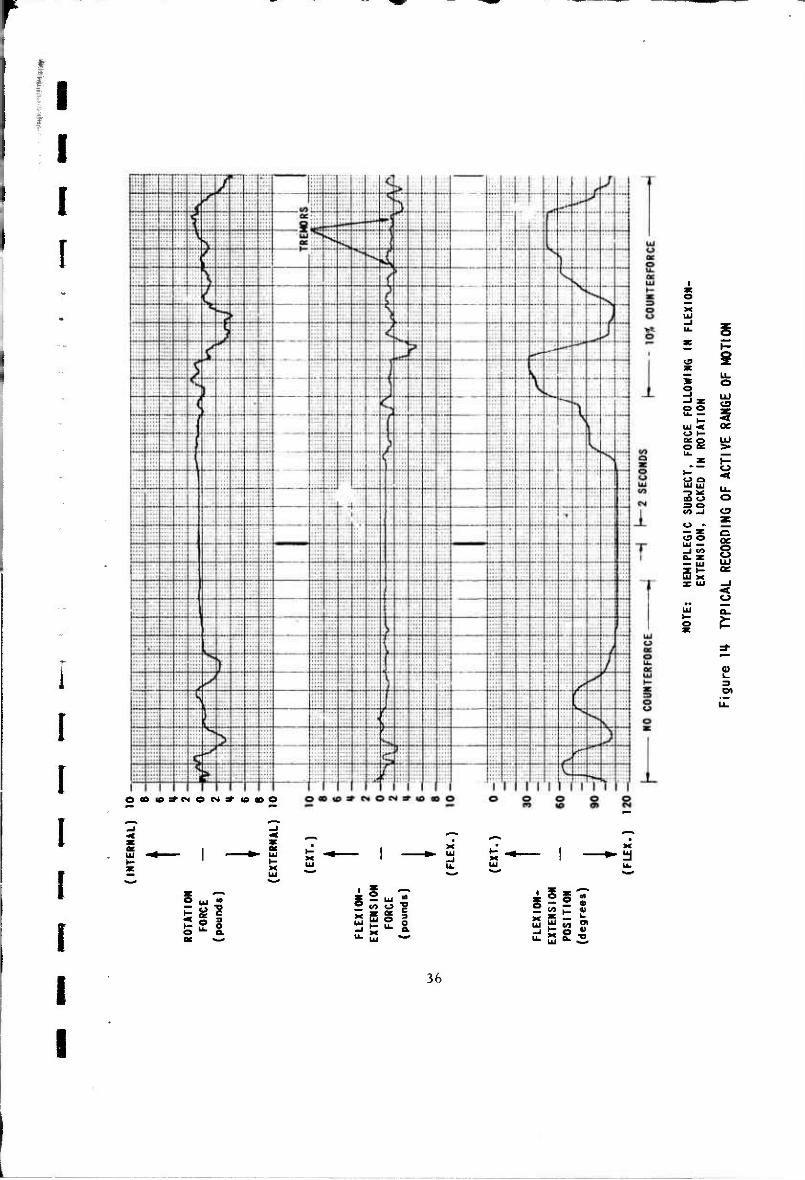
The behavior of a hemiplegic subject is shown in Figure 14.
(Normal subjects, of course, could control the arm over the full range between
the position limits. ) The subject was instructed to move his arm as far as
possible in each direction. Repeated trials resulted in a maximum excursion
of about plus and minus 25 degrees from the anatomical 90 degree position
for this particular subject.
With the subject's arm relaxed, a counterforce was added in
the extension direction, causing the arm to extend to a position where the
counterforce was balanced by the subject's natural rigidity force, and the
subject was again requested to move his arm as far as possible in each
direction. The latter portion of the record shown in Figure 14 shows the
increase in range of motion attained with the addition of a 10 percent counter-
force (in this case, 1 pound). The counterforce was increased to 1 5 percent,
at which point this subject could control his arm over the full 0 to 120 degree
range. With only a few minutes of practice, he was able to follow motions
indicated by the therapist, and to select and hold specified angles.
Note the two tremor oscillations indicated by the arrows in
Figure 14. This portion of the tape recording was played back again on the
chart recorder at a higher chart speed and gain setting to amplify the tremor
detail, as shown in Figure 15. These two tremors occurred when the arm
was at rest, negating the possibility of a machine artifact, and have a basic
frequency of 12 Hz.
3. Constant Vel city Measurements of Relaxed Arm Residual Forces
An experiment was devised to demonstrate the measurement of
spastic rigidity forces as a function of passive arm movement. The subject was
requested to neither aid nor oppose the motions of the machine, and various
combinations of flexion-extension movements at constant velocities were
performed. The amplitude of the movement was varied from a very small
deviations from the 60 degree position, to deviations over nearly his full
range of motion. The direction of motion was reversed instantly at each
extreme for some tests, and stopped for a short pause in other tests. A
35
I I F !
!
i ae o
1
3 ° £2 % ui •< QC o h- ap Ui
Sa a Si UJ L,
SS o S3 o o . E — Z ß
UJ — g
^s 8
2?
O« (fi*NO N* 10(00
I I
© u W
£ « ? S2U - - v> c "?
••• 1*1 *^
g2§S — «>»-«» x m — "• 2 £ «o ?
i i
36

I I r
r
!
I
3
st- ar
CO
I I I I I I I I I I
o CO
I CO
o 3= CO
o s o UJ
5
in
0) k.
CO C<4 — © ~ CM CO
I i I I
O ... <A
t £ ° o o. DC —
if _. = uj <fl £ <o o «
S £ £ o X * — L-
37
i

I [ I
I i !
I I I
constant velocity was achieved by having the device follow an external position
command generated by a triangular wave function generator. The involuntary
forces present as a function of flexion-extension position, velocity and accel-
eration are measured. As in the range of motion measurements, the flexion-
extension sweep was in the horizontal plane, avoiding the gravity vector effect.
Figure 16 and 17 show the comparative forces exhibited by a
normal subject and a hemiplegic subject at relatively slow velocities. The
normal subject residual force is less than 0.5 pounds in all instances (or
approximately 1 percent of his maximum capability), whereas the hemiplegic
subject exhibits a flexion-extension force pattern much like that of a spring,
with amplitudes approaching 2 pounds (or approximately 25 percent of his
maximum capability), where the force is proportional to the deflection. When
the arm is halted at the position extremes, the force remains at a constant
level, indicating that the force is primarily due to the arm position, and not
the velocity, A distinctive pattern is exhibited by the record of the rotational
force component, although no motion in the rotation axis had occurred.
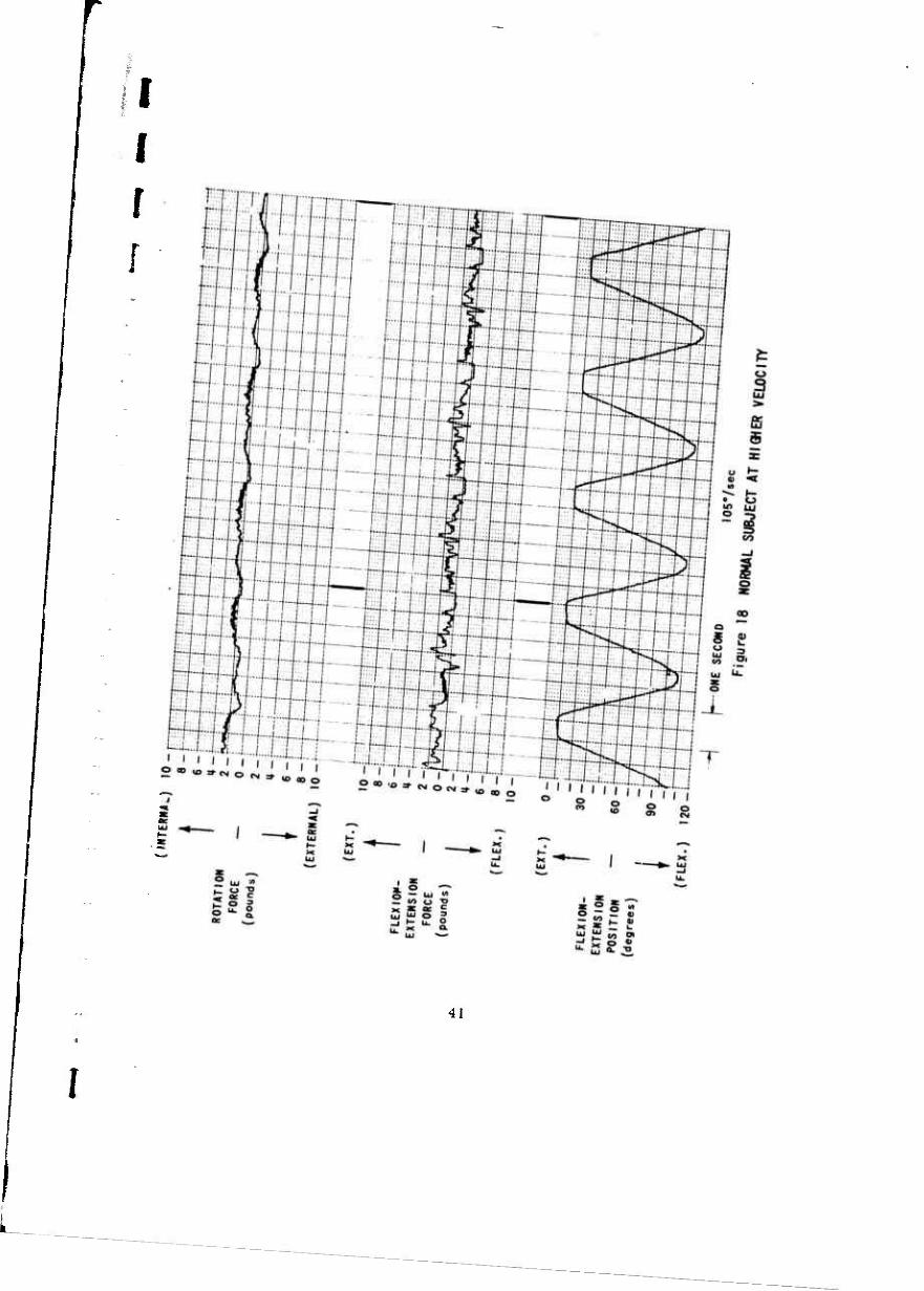
Figures 18 and 19 show the same comparison at a higher
velocity. The normal subject's force trace shows the inertia effects of rapidly
stopping and starting the limp arm, but the average forces during travel are
nearly zero. The hemiplegic subject exhibits the same basic force pattern as
at the slower velocity, with less inertia effects than those shown by the normal
subject's force record, perhaps due to the continuous muscle tension.
Figure 20 shows the same hemiplegic subject two days later.
No attempt was made to determine the cause of the change in response
indicated, other than to carefully ascertain that the experiment conditions
were the same. Note that the rotation force component patte rn has also
changed markedly. The most significant portion of this new force behavior
is that although the arm movement stops for nearly 0.8 seconds at the flexion
extreme, the opposing force does not remain a constant as before, but con-
tinues to a peak value of nearly twice the previous level. The cause nf this
reflex contraction has not been sought, and appears worthy of further
investigation.
38

I I F
05
UJ X
Ul DC
©
i °
So
55 CO
o o
CD
CT
O
I I I I I I I I I I I on ID^NO N 1 »COO
I X
J- O T3
C
C=>
O u.
3 0 a.
DC >—»
2 C/> O "J? x * 85 = 2»ü »
-• >< 9 •£ U. **, Q. "°
I 39

I 3= GO
o UJ
2
o o UJ —I
s
s oc UJ
o I oe I o
— GO O UJ O on ÜJ UJ >• it
h- -I $ o
££ Q O. o GO
r--
2!
TTT nrrT f rr r O 00 iD^NONilOioO o o o c o co u> e> cs
x
O uj V»
o •*• o. or *-»
2 w» «J "?
sgf i u_ . - -
e«>z % 2 £ •» ST -j C o • «- S *• 3
i 40
i
je
I I r
41
I
L

f [
o 3 5» ffi 5
a o a s! 5
OOOi£>:^CM©CN=* IO DO OOOlO^NON'lOCOO
£ 3 ? fc 2 ° © Ok ec -—
£ - w •£ - "> « c
Si* I g2|S 2 «* i_ • 5 W CA »
^ 2 s 3
42
i

>- •< Q
S
© ac
— x
it * X
ui tu
CD u_
y o — —* S LU
O
o CM
<D L.
I I I I I I I I I I OB»3'NON*I0100
a
581 o "• 5.
5 — •** £ 2 <« o ? 5 S ° o u- 2 «-*
«2S -
2 £ « ? «•2fc2
43
1

I I r These three experiments indicate primarily that this instrument is
capable of measuring spasticity forces under controlled conditions, and has
the potential for revealing details of muscular behavior in a unique new form,
i
1 44
i

I I I f I
I I I i I I
4. CONCLUSIONS AND RECOMMENDATIONS
The Myotron, as implemented in the present two-axis instrument, has been
shown to be technically practical and conceptually valid. The measurement of
dynamic muscular forces with a servocontrolled exoskeleton is a powerful
new research technique for the study of neuromuscular behavior. The ex-
perience gained by the development and evaluation of this two-axis instrument,
however, indicates that the extension of this concept to a full-body Myotron,
even if limited to a 33-axis exoskeleton, would be a major undertaking.
Although development of the full-body Myotron is technically possible today,
the operational complexity and data reduction problems appear to question the
utility of this approach. Further operational experience with a less complex
instrument is desirable before developing a full-body unit. The use of a
Myotron with up to, say, four controlled axes, is undoubtedly practical for
the study of additional limb movements and muscle groups. The present two-
axis Myotron can be used to obtain much valuable information for effective
development of an eventual full-body device.
Specifically, this research program has revealed that the man-machine
interface problems are not as severe as expected. The body attachment and
fixation techniques devised are simple and adequate. No adverse subject
reaction to being restrained in this mechanical device was encountered, and
neither the noise nor the "feel" of the machine interfered with the subject's
ability to perform the required tasks and procedures. Under all circumstances
incurred during this 3-month evaluation program, the safety measures proved
adequate in protecting the subject from unintended motion extremes. Interference
with other sensitive electrical instruments, particularly with an electromyograph
attached to the subject, v/as not detectable. The operational flexibility and
measurement sensitivity and accuracy proved adequate for the type of experiments
necessary for the study of neuromuscular disorders. In particular, fatigue
tremors were often recorded routinely, and illustrate the potential for
quantitative assessment ol tremor severity.
The general working knowledge gained about the operational capabilities
of the instrument indicate that a wide variety of neuromuscular research ex-
periments are practical. Although the evaluation experiments were limited
45

I I I F !
in scope, the direct results of these experiments suggest three particular
research areas of sufficient importance to warrant further study.
1. basic research studies of flaccid and spastic paralysis muscular
behavior, for detecting the participation of specific muscles or
muscle groups, for diagnosing the nature of the disorder, and
for observing the effects of drug or therapy treatments.
2. research studies of new therapy techniques in the management
and control of spasticity, particularly in the area of patient-
controlled coordination movement exercises using the counterforce
aided force-following mode of operation (From an engineering
standpoint, this type of therapy should be as effective as speech
therapy in the rehabilitation of stroke victims because it would
allow natural feedback to the central nervous system of all the
limb activity sensors, and thus enhance the formation of new
command processes.)
3. research studies to determine and evaluate the problems to be
encountered in applying the force-following technique for
developing micro-force following powered orthotic devices.
These research activities can be pursued using the present two-axis
Myotron. However, it is recommended that modifications in the mechanical
structure be considered to improve the accuracy and reliability of the present
feasibility model. Specifically, the stvain-ring should be re-fabricated using
a less lossy spring material to reduce the hysteresis effect (presently about
4 percent for maximum loads and 10 percent for one pound loads), and in-
corporating a larger wrist opening to facilitate the passage of the typical
clenched fist of the spastic subject. In addition, an improved drive mechanism
f should be considered to reduce gear cogging effects and increase the torque
* transmission efficiency (presently 30 percent, but could be 90 percent).
ff Future development efforts for constructing other Myotron instruments
• should consider incorporation of the following:
i i i
1. electronic analog computer circuits to automatically counter-
balance the limb gravity forces in the force-following mode,
46

I 2. lighter weight attachment fittings at the force sensing points
to minimize inertia effects, and
3. an integral adjustable body support mechanism.
Further experience with the present instrument will undoubtedly result in
additional recommendations for design improvements.
In summary, this research program has demonstrated the utility of the
Myotron concept and provided medical researchers with an instrument with
potential for revealing new information about the nature of neuromuscular
activity.
47
i
I I I f r
i
I I I
5. SELECTED BIBLIOGRAPHY
Clark, D.C«, N.J. DeLeys, and C.W. Matheis, Exploratory Investigation of the Man Amplifier Concept, Report No. AMRL-TDR-62-89, Cornell Aeronautical Laboratory Report No. VO-1616-V-1, April 1962
Mizen, N.J., Design and Test of a Full-Scale Wearable Exoskeletal Structure, Report No. VO-1692-V-4, Cornell Aeronautical Laboratory, Buffalo, New York, March 1964
Mizen, N.J., Preliminary Design for the Shoulders and Arms of a Powered Exoskeletal Structure, Report No. VO-16921V-4, Cornell Aeronautical Laboratory, Buffalo, New York, June 1965
Webster, David D., M.D., A Method of Measuring the Dynamic Characteristics of Muscle Rigidity, Strength, and Tremor in the Upper Extremity, I. R.E. Transactions of Medical Electronics, September 1959
Webster, David D., M.D., Dynamic Measurement of Rigidity, Strength and Tremor in Parkinson Patients Before and After Destruction of Mesial Globus Pallidus, "Neurology" 1959, pp. 157-163
Herman, Richard, Herbert Schaumburg, Stuart Reiner, A Rotational Joint Apparatus: A Device for Study of Tension-Length Relations of Human Muscle, Medical Research Engineering, Fourth Quarter 1967, pp. 18-20
Eppler, W.G., Study of Human Tracking Performance Based on the Use of Various Output Variables (Technical Report) Lockheed Missiles and Space Co., Div. of Lockheed Aircraft Corporation, Sunnyvale, California No. 6-65-65-27, October 1965
Ralston, H.J., Ph.D., Mechanics of Voluntary Muscle (Special Review) American Journal of Physical Medicine, Volume 32 (1953), pp. 166-185
Williams, Marian, Ph.D., Leon Stutzman, M.A., Strength Variation Through the Range of Joint Motion, The Physical Therapy Review (1959), 39, 145-152
Wilkie, D. R., The Relation Between Force and Velocity in Human Muscle, Journal of Physiology (1950) 110, 249-280
Boshes, Benjamin, M. D., Hirsh Wacks, M.D., Joel Brumlik, M. D., Namuel Mier, M.D. Matthew Petrovick, B.S.E.E., Studies of Tone, Tremor, and Speech in Normal Persons and Parkineonian Patients, "Neurology" Vol 10 Number 9, 1959» pp. 805-813
48

*.»
I Spiegel, E.A., M.D., H.T. Wyris, M. D., H.W. Baird III. M. D., D. Rovner, M.D., C. Thur, Pallidum and Muscle Tone, "Neurology" 1956 pp. 350-353
Lippold, 0,C«J.„ The Relation Between Integrated Action Potentials in a Human Muscle and Its Isometric Tension, Journal of Physiology (1952) 117-492-499
Angel, R.W., W. Eppler, A, Iannone, Silent Period Produced by Unloading of Muscle During Voluntary Contraction, Journal of Physiology (1965) 180, 864-870
i 49