Embed Size (px)
Citation preview
1
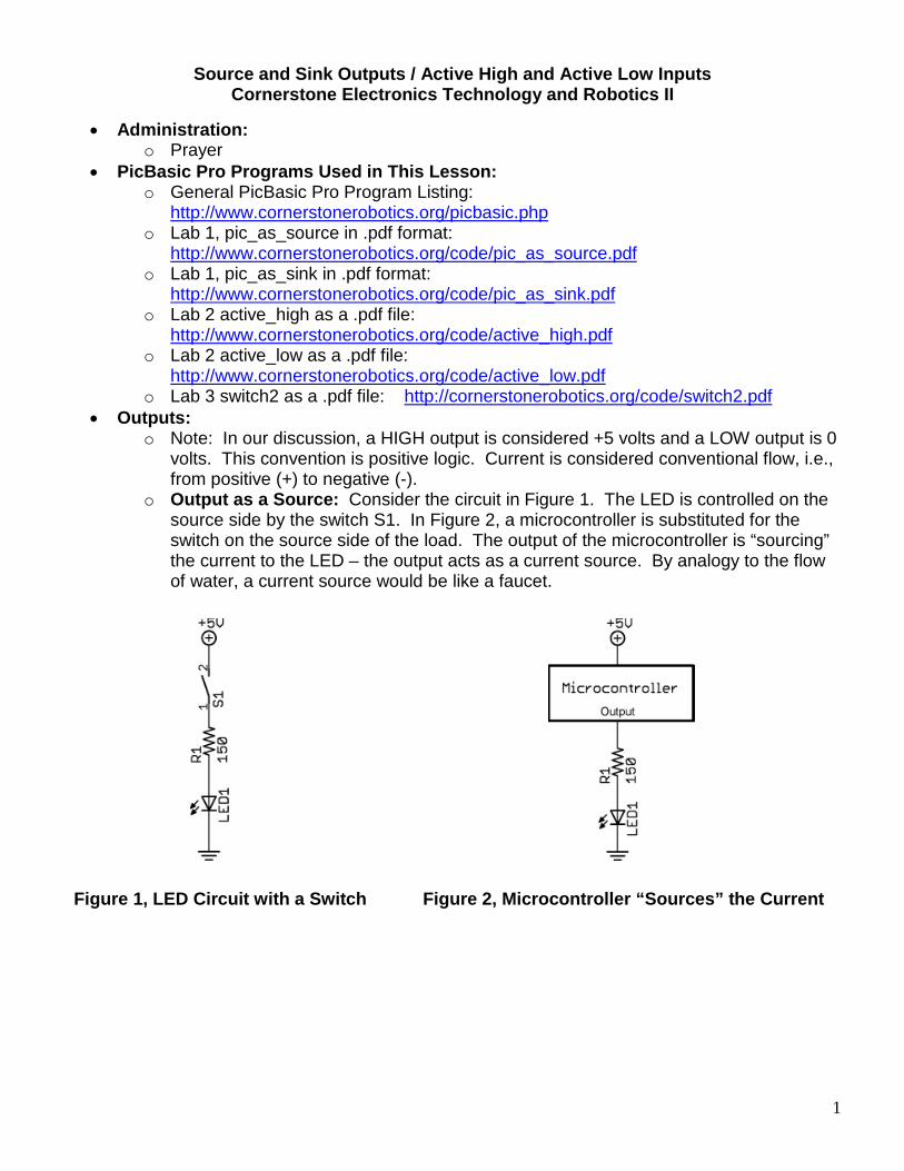
Source and Sink Outputs / Active High and Active Low Inputs Cornerstone Electronics Technology and Robotics II
• Administration:
o Prayer • PicBasic Pro Programs Used in This Lesson:
o General PicBasic Pro Program Listing: http://www.cornerstonerobotics.org/picbasic.php
o Lab 1, pic_as_source in .pdf format: http://www.cornerstonerobotics.org/code/pic_as_source.pdf
o Lab 1, pic_as_sink in .pdf format: http://www.cornerstonerobotics.org/code/pic_as_sink.pdf
o Lab 2 active_high as a .pdf file: http://www.cornerstonerobotics.org/code/active_high.pdf
o Lab 2 active_low as a .pdf file: http://www.cornerstonerobotics.org/code/active_low.pdf
o Lab 3 switch2 as a .pdf file: http://cornerstonerobotics.org/code/switch2.pdf • Outputs:
o Note: In our discussion, a HIGH output is considered +5 volts and a LOW output is 0 volts. This convention is positive logic. Current is considered conventional flow, i.e., from positive (+) to negative (-).
o Output as a Source: Consider the circuit in Figure 1. The LED is controlled on the source side by the switch S1. In Figure 2, a microcontroller is substituted for the switch on the source side of the load. The output of the microcontroller is “sourcing” the current to the LED – the output acts as a current source. By analogy to the flow of water, a current source would be like a faucet.
Figure 1, LED Circuit with a Switch Figure 2, Microcontroller “Sources” the Current
2
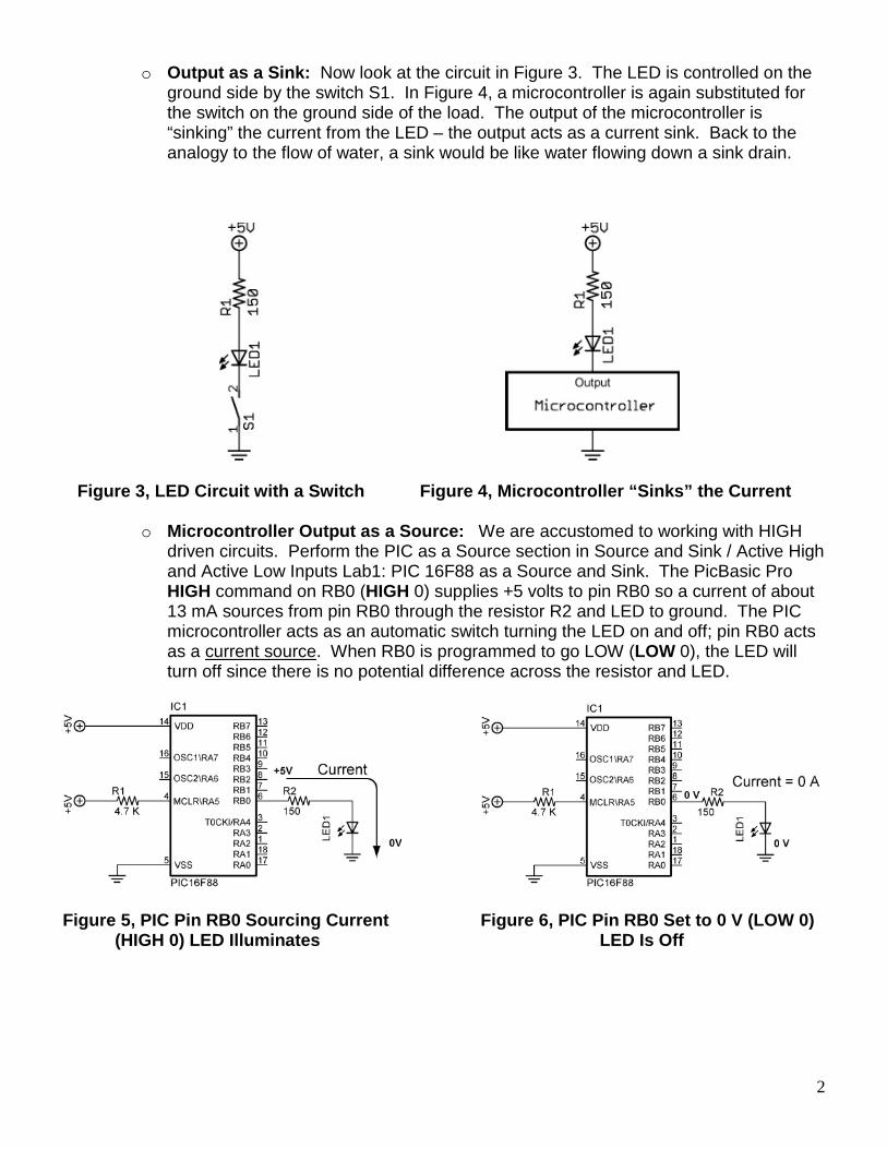
o Output as a Sink: Now look at the circuit in Figure 3. The LED is controlled on the ground side by the switch S1. In Figure 4, a microcontroller is again substituted for the switch on the ground side of the load. The output of the microcontroller is “sinking” the current from the LED – the output acts as a current sink. Back to the analogy to the flow of water, a sink would be like water flowing down a sink drain.
Figure 3, LED Circuit with a Switch Figure 4, Microcontroller “Sinks” the Current
o Microcontroller Output as a Source: We are accustomed to working with HIGH driven circuits. Perform the PIC as a Source section in Source and Sink / Active High and Active Low Inputs Lab1: PIC 16F88 as a Source and Sink. The PicBasic Pro HIGH command on RB0 (HIGH 0) supplies +5 volts to pin RB0 so a current of about 13 mA sources from pin RB0 through the resistor R2 and LED to ground. The PIC microcontroller acts as an automatic switch turning the LED on and off; pin RB0 acts as a current source. When RB0 is programmed to go LOW (LOW 0), the LED will turn off since there is no potential difference across the resistor and LED.
Figure 5, PIC Pin RB0 Sourcing Current Figure 6, PIC Pin RB0 Set to 0 V (LOW 0) (HIGH 0) LED Illuminates LED Is Off
3
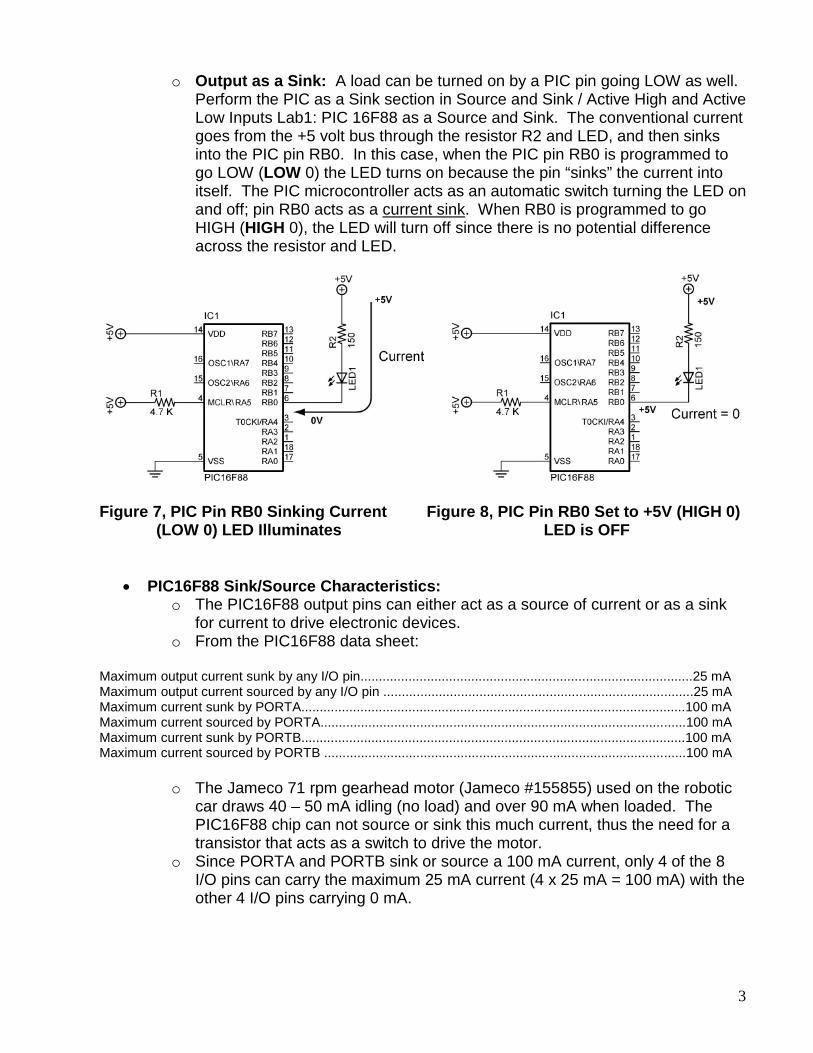
o Output as a Sink: A load can be turned on by a PIC pin going LOW as well. Perform the PIC as a Sink section in Source and Sink / Active High and Active Low Inputs Lab1: PIC 16F88 as a Source and Sink. The conventional current goes from the +5 volt bus through the resistor R2 and LED, and then sinks into the PIC pin RB0. In this case, when the PIC pin RB0 is programmed to go LOW (LOW 0) the LED turns on because the pin “sinks” the current into itself. The PIC microcontroller acts as an automatic switch turning the LED on and off; pin RB0 acts as a current sink. When RB0 is programmed to go HIGH (HIGH 0), the LED will turn off since there is no potential difference across the resistor and LED.
Figure 7, PIC Pin RB0 Sinking Current Figure 8, PIC Pin RB0 Set to +5V (HIGH 0) (LOW 0) LED Illuminates LED is OFF
• PIC16F88 Sink/Source Characteristics: o The PIC16F88 output pins can either act as a source of current or as a sink
for current to drive electronic devices. o From the PIC16F88 data sheet:
Maximum output current sunk by any I/O pin..........................................................................................25 mA Maximum output current sourced by any I/O pin ....................................................................................25 mA Maximum current sunk by PORTA........................................................................................................100 mA Maximum current sourced by PORTA...................................................................................................100 mA Maximum current sunk by PORTB........................................................................................................100 mA Maximum current sourced by PORTB ..................................................................................................100 mA
o The Jameco 71 rpm gearhead motor (Jameco #155855) used on the robotic car draws 40 – 50 mA idling (no load) and over 90 mA when loaded. The PIC16F88 chip can not source or sink this much current, thus the need for a transistor that acts as a switch to drive the motor.
o Since PORTA and PORTB sink or source a 100 mA current, only 4 of the 8 I/O pins can carry the maximum 25 mA current (4 x 25 mA = 100 mA) with the other 4 I/O pins carrying 0 mA.
4
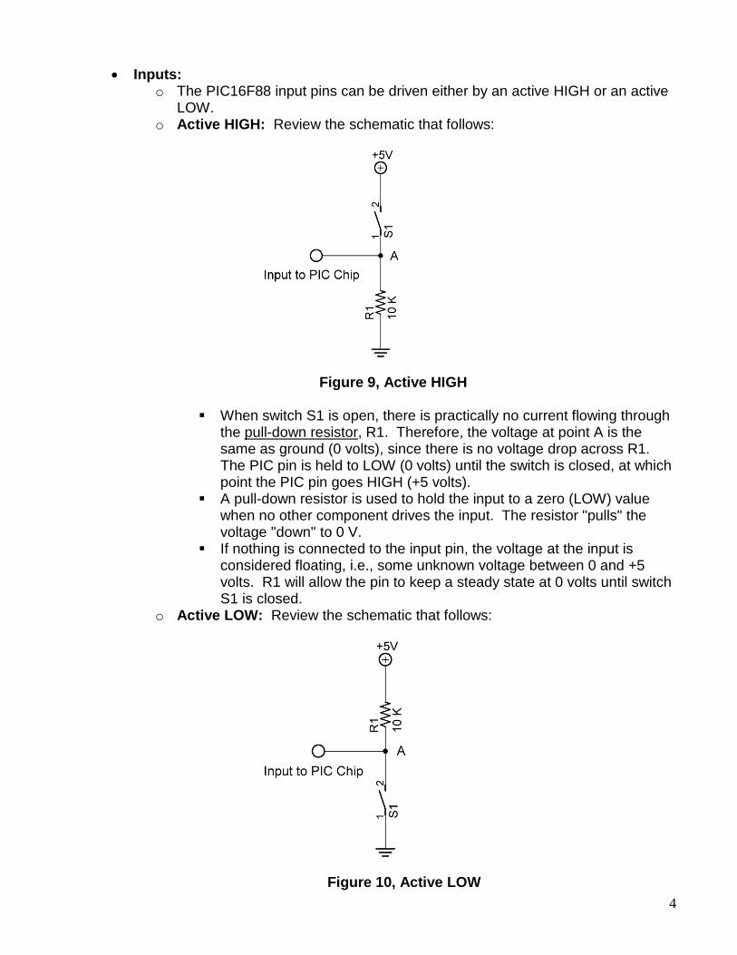
• Inputs: o The PIC16F88 input pins can be driven either by an active HIGH or an active
LOW. o Active HIGH: Review the schematic that follows:
Figure 9, Active HIGH
When switch S1 is open, there is practically no current flowing through the pull-down resistor, R1. Therefore, the voltage at point A is the same as ground (0 volts), since there is no voltage drop across R1. The PIC pin is held to LOW (0 volts) until the switch is closed, at which point the PIC pin goes HIGH (+5 volts).
A pull-down resistor is used to hold the input to a zero (LOW) value when no other component drives the input. The resistor "pulls" the voltage "down" to 0 V.
If nothing is connected to the input pin, the voltage at the input is considered floating, i.e., some unknown voltage between 0 and +5 volts. R1 will allow the pin to keep a steady state at 0 volts until switch S1 is closed.
o Active LOW: Review the schematic that follows:
Figure 10, Active LOW

5
Again, when switch S1 is open again there is practically no current flowing through the pull-up resistor, R1. Therefore the voltage at point A is the same as +5 volts, since there is no voltage drop across R1. The PIC pin is held to HIGH (+5 volts) until the switch is closed, at which point the PIC pin goes LOW (0 volts).
A pull-up resistor is used to hold the input to +5 V (HIGH) value when no other component drives the input. The resistor "pulls" the voltage "up" to +5 V.
o Related Web Site: http://www.seattlerobotics.org/encoder/mar97/basics.html http://www.winpicprog.co.uk/pic_tutorial_extras.htm
• PicBasic Pro Comparison Operators: o Compares one expression with another o Can not be used to compare a number less than 0 o Used in IF..THEN statements o List of comparison operators:
Comparison Description Operator = or == Equal <> or != Not Equal
< Less Than > Greater Than
<= Less Than or Equal >= Greater Than or Equal
• PicBasic Pro Logical Operators: o Used with comparison operators in IF..THEN statements o Gives a true or false result o Value of 0 are false o Any other value is true
Logical Description
Operator AND or && Logical AND
OR or !! Logical OR XOR or ^^ Logical Exclusive OR NOT or ! Logical NOT ANDNOT Logical NAND ORNOT Logical NOR
XORNOT Logical NXOR
6
• PicBasic Programming: o New PicBasic Commands:
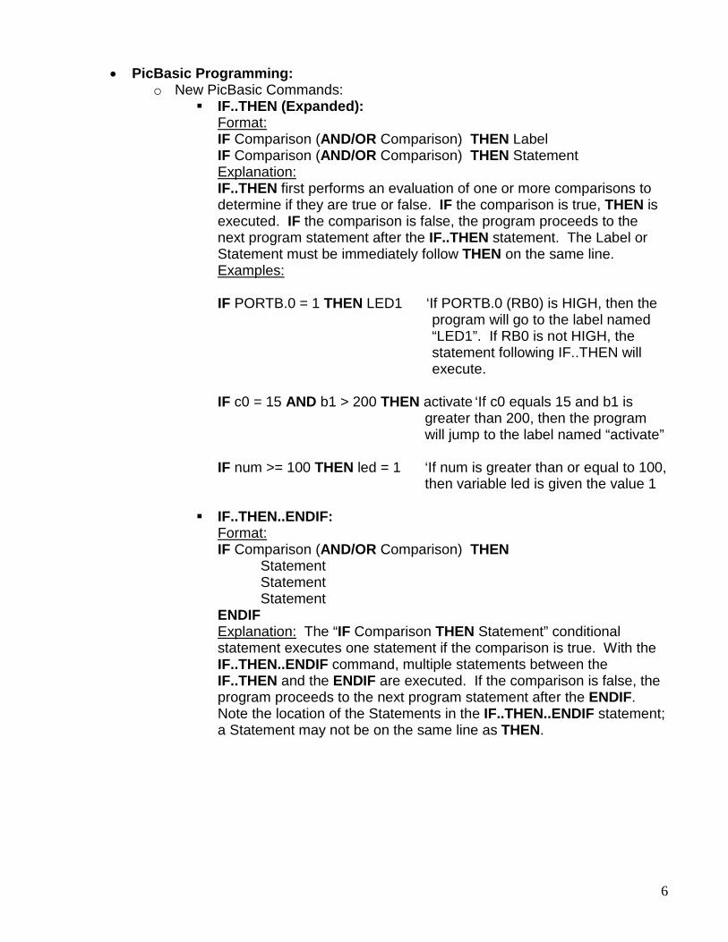
IF..THEN (Expanded): Format: IF Comparison (AND/OR Comparison) THEN Label IF Comparison (AND/OR Comparison) THEN Statement Explanation: IF..THEN first performs an evaluation of one or more comparisons to determine if they are true or false. IF the comparison is true, THEN is executed. IF the comparison is false, the program proceeds to the next program statement after the IF..THEN statement. The Label or Statement must be immediately follow THEN on the same line. Examples: IF PORTB.0 = 1 THEN LED1 ‘If PORTB.0 (RB0) is HIGH, then the
program will go to the label named “LED1”. If RB0 is not HIGH, the statement following IF..THEN will execute.
IF c0 = 15 AND b1 > 200 THEN activate ‘If c0 equals 15 and b1 is
greater than 200, then the program will jump to the label named “activate”
IF num >= 100 THEN led = 1 ‘If num is greater than or equal to 100,
then variable led is given the value 1
IF..THEN..ENDIF: Format: IF Comparison (AND/OR Comparison) THEN Statement Statement Statement ENDIF
Explanation: The “IF Comparison THEN Statement” conditional statement executes one statement if the comparison is true. With the IF..THEN..ENDIF command, multiple statements between the IF..THEN and the ENDIF are executed. If the comparison is false, the program proceeds to the next program statement after the ENDIF. Note the location of the Statements in the IF..THEN..ENDIF statement; a Statement may not be on the same line as THEN.

7
o Formats for IF..THEN Statements: IF..THEN:
IF comparison(s) THEN statement
IF..THEN..ENDIF: IF comparison(s) THEN statement statement statement… ENDIF
IF..THEN..ELSE..ENDIF: IF comparison(s) THEN statement statement… ELSE statement statement… ENDIF
o Complete Active HIGH – Active LOW LAB 2 – switch1.pbp o Perform Active HIGH – Active LOW LAB 3 – switch2.pbp
8
Cornerstone Electronics Technology and Robotics II Sink and Source Outputs / Active High and Active Low Inputs
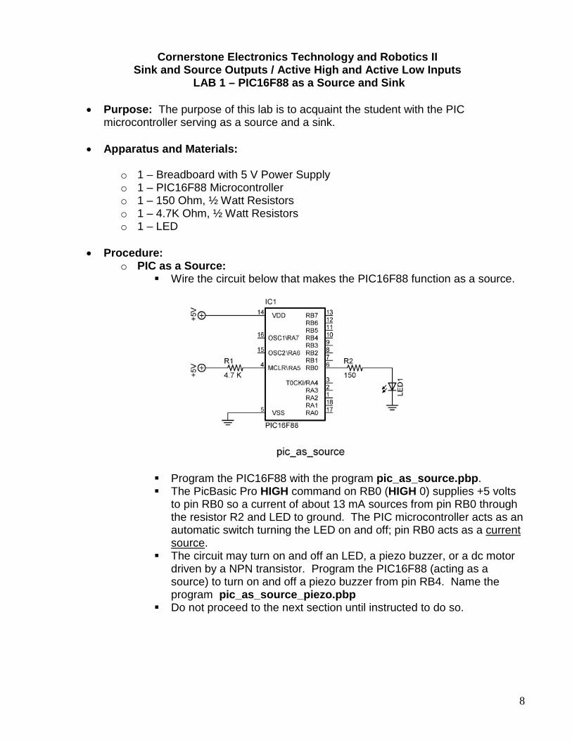
LAB 1 – PIC16F88 as a Source and Sink
• Purpose: The purpose of this lab is to acquaint the student with the PIC microcontroller serving as a source and a sink.
• Apparatus and Materials:
o 1 – Breadboard with 5 V Power Supply o 1 – PIC16F88 Microcontroller o 1 – 150 Ohm, ½ Watt Resistors o 1 – 4.7K Ohm, ½ Watt Resistors o 1 – LED
• Procedure:
o PIC as a Source: Wire the circuit below that makes the PIC16F88 function as a source.
Program the PIC16F88 with the program pic_as_source.pbp. The PicBasic Pro HIGH command on RB0 (HIGH 0) supplies +5 volts
to pin RB0 so a current of about 13 mA sources from pin RB0 through the resistor R2 and LED to ground. The PIC microcontroller acts as an automatic switch turning the LED on and off; pin RB0 acts as a current source.
The circuit may turn on and off an LED, a piezo buzzer, or a dc motor driven by a NPN transistor. Program the PIC16F88 (acting as a source) to turn on and off a piezo buzzer from pin RB4. Name the program pic_as_source_piezo.pbp
Do not proceed to the next section until instructed to do so.
9
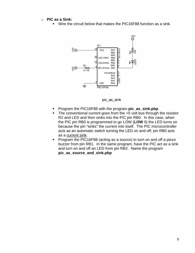
o PIC as a Sink: Wire the circuit below that makes the PIC16F88 function as a sink.
Program the PIC16F88 with the program pic_as_sink.pbp. The conventional current goes from the +5 volt bus through the resistor
R2 and LED and then sinks into the PIC pin RB0. In this case, when the PIC pin RB0 is programmed to go LOW (LOW 0) the LED turns on because the pin “sinks” the current into itself. The PIC microcontroller acts as an automatic switch turning the LED on and off; pin RB0 acts as a current sink.
Program the PIC16F88 (acting as a source) to turn on and off a piezo buzzer from pin RB1. In the same program, have the PIC act as a sink and turn on and off an LED from pin RB2. Name the program pic_as_source_and_sink.pbp
10
Cornerstone Electronics Technology and Robotics II Sink and Source Outputs / Active High and Active Low Inputs
LAB 2 – Active High and Active Low Inputs
• Purpose: The purpose of this lab is to acquaint the student with the PicBasic Pro command IF..THEN and the principles of active HIGH and active LOW. In addition, the student is challenged to use the logical operator AND.
• Apparatus and Materials:
o 1 – Analog/Digital Trainer o 1 – PIC 16F88 Microcontroller o 1 – 4.7K Ohm, ½ Watt Resistors o 1 – 150 Ohm, ½ Watt Resistors o 1 – 10 K Ohm, ½ Watt Resistor o 1 – 1K, ½ Watt Resistor o 1 – NO Momentary Switch o 1 – LEDs o This list does not contain the parts needed for the challenges.
• Procedure:
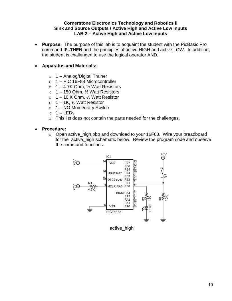
o Open active_high.pbp and download to your 16F88. Wire your breadboard for the active_high schematic below. Review the program code and observe the command functions.
11
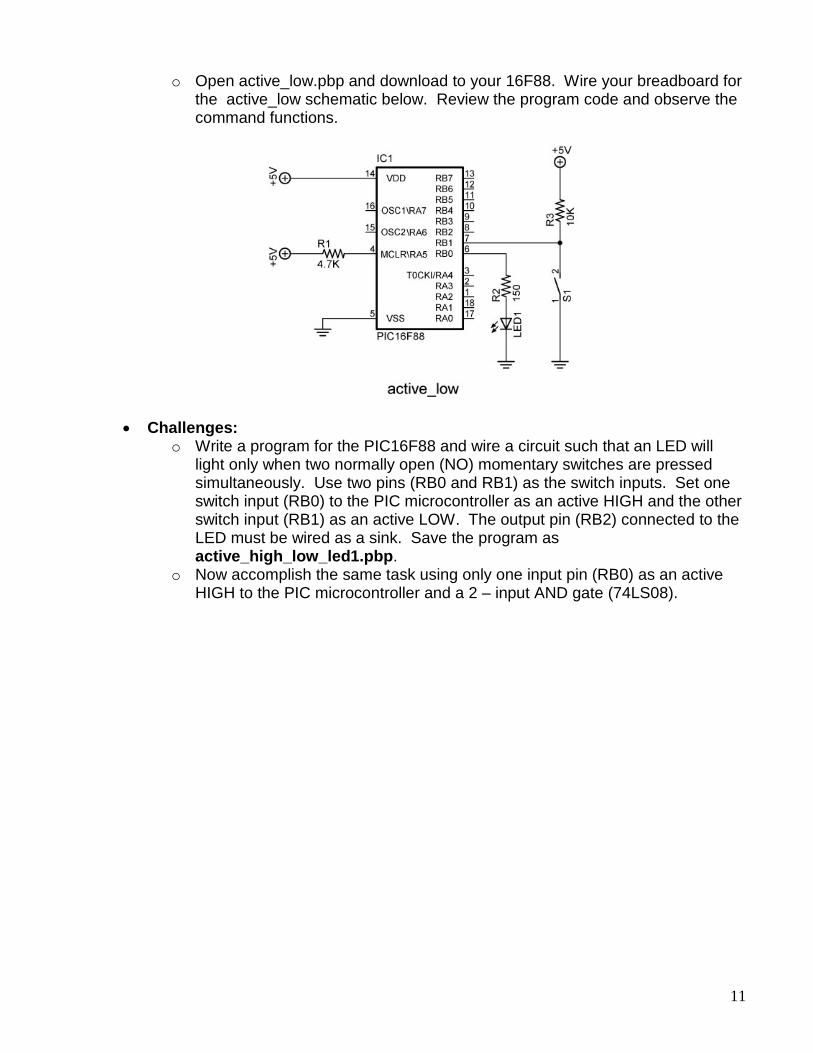
o Open active_low.pbp and download to your 16F88. Wire your breadboard for the active_low schematic below. Review the program code and observe the command functions.
• Challenges: o Write a program for the PIC16F88 and wire a circuit such that an LED will
light only when two normally open (NO) momentary switches are pressed simultaneously. Use two pins (RB0 and RB1) as the switch inputs. Set one switch input (RB0) to the PIC microcontroller as an active HIGH and the other switch input (RB1) as an active LOW. The output pin (RB2) connected to the LED must be wired as a sink. Save the program as active_high_low_led1.pbp.
o Now accomplish the same task using only one input pin (RB0) as an active HIGH to the PIC microcontroller and a 2 – input AND gate (74LS08).
12
Cornerstone Electronics Technology and Robotics II Sink and Source Outputs / Active High and Active Low Inputs
LAB 3 – switch2.pbp
• Purpose: The purpose of this lab is to reinforce the principles of active HIGH and active LOW. In addition, the student is challenged to use the logical operator OR.
• Apparatus and Materials:
o 1 – Breadboard or Analog/Digital Trainer o 1 – PIC16F88 Microcontroller o 1 – 150 Ohm, ½ Watt Resistors o 1 – 10 K Ohm, ½ Watt Resistor o 1 – 4.7K Ohm, ½ Watt Resistor o 1 – NO Momentary Switch o 1 – LED o 1 – Servomotor(not “hacked”) o This list does not contain the parts needed for the challenges.
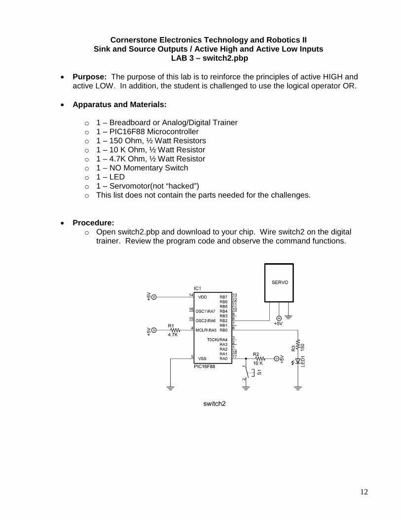
• Procedure: o Open switch2.pbp and download to your chip. Wire switch2 on the digital
trainer. Review the program code and observe the command functions.

13
• Challenges: o Write a program and wire a circuit so that when either one of two normally
open (NO) switches is pressed, an LED will light. Use two pins (RB0 and RB1) as the switch inputs. Set one switch input (RB0) to the PIC microcontroller as an active HIGH and the other switch input (RB1) as an active LOW. The output pin (RB2) connected to the LED must be wired as a sink. Save the program as active_high_low_led2.pbp.
o Now accomplish the same task using only one input pin on the PIC microcontroller and a 2 – input OR gate.
o Write a program and wire the robotic car to make it turn left if the left lever switch is pressed and to turn right if the right lever switch is pressed. If both switches are pressed, make the car travel forward.


![[Ebook - Electronics] Introductory Robotics - J. M. Selig.pdf](https://img.pdfslide.net/doc/110x75/577c7e411a28abe054a0d0f2/ebook-electronics-introductory-robotics-j-m-seligpdf.jpg)


![[Ebook - Electronics] Introductory Robotics - J M Selig](https://img.pdfslide.net/doc/110x75/5464bb08af795997368b4a1c/ebook-electronics-introductory-robotics-j-m-selig.jpg)