Embed Size (px)
Citation preview

Corrosion and Hydriding Model for Zircaloy-2 Pressure tubes of Indian PHWRs
S K Sinha & R K SinhaS.K. Sinha & R.K. SinhaBhabha Atomic Research Centre, Mumbai
India
ASTM-2013, Hyderabad1Feb.5, 2013

Scope of presentation
• Introduction of the component• Background • Role of analytical models in the life management
programme of pressure tubes• Modelling work• Modelling work• Results• Conclusion
Feb.5, 2013 ASTM-2013, Hyderabad 2

The pressure which is a part of the Coolant Channelassembly is structurally simple in design but operatesunder severe in-reactor environmentunder severe in-reactor environment
•(Zr-2/Zr-Nb) •(Zr-2)
(Zr+2 5Nb
PRESSURE TUBE
•(Zr+2.5Nb+0.5Cu)
•[573 K]•[350 K]
•(SS 403)
1 2
220 MWe PHWR: 306 Channels, typically 5.2 m PT Length & 83 mm PT ID
Temp = 250 – 300 C, Pressure = 10 MPa, Neutron flux = 2.5 x 10¹⁷ n/m2/sec
Feb.5, 2013 ASTM-2013, Hyderabad
3
540 MWe PHWR: 392 Channels, typically 6.2 m PT Length & 104 mm PT ID

The components have limited service life due to operatingcomplex in-reactor material degradation mechanisms.
Mechanisms PT (Zr-2/ Zr-2.5Nb) CT (Zr-2/ Zr-4)
GS (Zr-2.5Nb-0.5Cu)
EF (SS-403)
Fast neutron Irradiation Enhanced Creep & G th
Dimensional changesSagging
Sag, Axial force on End Shield (?)
Relaxation of tight-fit (?)
& Growth (?)In-service Corrosion & H d idi
• Local & Gross Hydride Embrittlement
H d id bli t D l d
(?) Hydride Reorientation
Hydride
(Hydrogen migrationHydriding • Hydride blisters, Delayed
hydride cracking (DHC)• Reduction in fracture
toughness
, Hydride blisters,DHC (?)
migration to PT ends)
toughness Fast neutron Irradiation Enhanced
Lowering of fracture toughness and ductility
Yes Yes Yes
4
Embrittlement
ASTM-2013, HyderabadFeb.5, 2013

In early 90s, Five units having Zircaloy-2 pressure tubes and loosefit design of garter springs were in the early years of operations ( 3
4 FPYs)– 4 FPYs).
S f ti f th it• Safe operation of the units• Life limiting issues
– PT-CT contact as result of shift of garter spring spacersPT CT contact as result of shift of garter spring spacers– Accelerated corrosion and hydriding– Possibility of hydride blistering at the contact locations
• Constriants– Life management programme was under initial stage of– Life management programme was under initial stage of
development.– Un-inspected reactor core
Feb.5, 2013 ASTM-2013, Hyderabad 5

Efforts were put on to develop methodology for assessment of fitnessfor service of the pressure tubes of these units by developing andintegratingintegrating
Analytical Models- SCAPCADiagnostic - SCAPCA- BLIST- HYCON-DELHYC
and Inspection Tools
- NIVDT C- NIVDT- BARCIS-WEST
Post Irradiation ExaminationAssessment Examination
- Microstructure- Mechanical Testing- H analysis
Methodology
H analysis-DHC velocity-Fracture toughness- Non-Destructive Life Extension
Feb.5, 2013ASTM-2013, Hyderabad
6
ExaminationTools– INGRES

Life management approach for an un-inspected reactor coreinvolved greater role of analytical models to reduce the inspectionload.
Conservatively analysed withUn-inspected Core
Conservatively analysed withworst possible inputs toidentify the pressure tubesmost likely to have hydridey yblisters at contact locationsfor the targeted time
Diagnostic andmonitoring toolsconfirmed theLikely hood of possibility ofhydride blisters atcontact locationsISI confirmed PT-CT
contacts
nucleation & growth of hydride blisters established anal ticall
Feb.5, 2013 ASTM-2013, Hyderabadwith 7
contactsanalytically

Analytical models developed for in-reactor degradationmechanisms for pressure tubes as a part of life managementprogramme had the key roles inprogramme had the key roles in
• reducing inspection burden• helping in taking safety related decisions
Built-in margin of conservatism initially provided to compensate for the lack of complete knowledge was progressively reduced with in-flow of knowledgein flow of knowledge.
8

Facts related to detrimental effects of hydrogen onZirconium alloy pressure tube materialy p
• Absorption of hydrogen in Zirconium alloys and its deleterious effect onstructural properties was identified as early as 1953.
• Most of Failures in pressure tubes in the history of CANDU type PHWRsoccurred in 70s and 80s have hydrogen as the root cause. Someexamples are– DHC at rolled joints
• 1974, Pickering-3, 17 Nos, g ,• 1975, Pickering-4, 61 Nos• 1982, Bruce-2, 2 Nos
– Blister formation at cold spots, cracking of series of blisters andBlister formation at cold spots, cracking of series of blisters andsudden rupture of PT
• 1983, Pickering-2 G16
Feb.5, 2013 ASTM-2013, Hyderabad 9

Thus, hydriding was identified as an important lifelimiting parameter of Zircaloy 2 pressure tubes andlimiting parameter of Zircaloy-2 pressure tubes andtherefore required continuous monitoring.
Feb.5, 2013 ASTM-2013, Hyderabad
10

Hydrogen ingress in pressure tube under operating conditionscan happen through various sources
• As an impurity in the as manufacturedpressure tube
• Corrosion reaction of zirconium alloyt b ith hi h t t h
This accounts foralmost all the in-reactor hydrogen
pressure tube with high temperature heavywater coolant
• Radiolysis of heavy water coolant
pick-up andnumerical modelsimulates theki ti f thi• Radiolysis of heavy water coolant
• Diffusion of hydrogen from the outer surfaceof pressure tube
kinetics of thisreaction.
p
• Diffusion of hydrogen from the SS Endfitting near the rolled joint region
ASTM-2013, Hyderabad 11Feb.5, 2013

Characteristics of corrosion & hydrogen pick-up inZircaloy-2 pressure tubeZircaloy-2 pressure tube
• Flat profile along the pressure tube length till certain oxide thickness (critical thickness or transition thickness)A l t d i• Accelerated corrosion
• Hydrogen pick-up profile follows oxide thickness profile
• In a typical high flux channel, the transition occurs approximately around 7 years of operation.
Feb.5, 2013 ASTM-2013, Hyderabad 12

Oxide and hydrogen pick-up variation in one of pressuretubes subjected to post-irradiation examination
Peak value
Peak value
Pre transition Pre transition
Peak value
Plateau region Pre transition Plateau region
Salient features• Plateau region• Transition point
Feb.5, 2013 ASTM-2013, Hyderabad
13
• region of acceleration• Peak point.

Oxidation Kinetics and Hydrogen pick-upOxidation Kinetics and Hydrogen pick-up
ASTM-2013, Hyderabad14Feb.5,
2013

Oxidation Kinetics & Hydrogen pick-up
• Zircaloy-2 (two stage kinetics)– Cubic pre-transition {dw3 =K *t}
K = A*exp(-Q/RT)Where, A t tCubic pre-transition {dw =Kpre t}
– Linear post-transition {dw = Kpost*t}
Wh
A = constantQ = Activation energyT = Temperature
Where, dw = oxide weight gainKpre = pre-transition rate constant
Hydrogen pick-up = fpup * Hcor(dw)
Wherep
Kpost = Post-transition rate constnatKp = parabolic rate constantt = time
Where,Hcor(dw) = Hydrogen evolved to
form ‘dw’ oxide f = fraction of Hydrogent time fpup fraction of Hydrogen
evolved picked-up by metal
ASTM-2013, Hyderabad 15Feb.5, 2013

Indian observations on Irradiation effect on Oxidation Kinetics
• Zircaloy-2– Out of pile pre-transition rate enhanced but no noticeable effect of
neutron fluence until the transition– Dominant effect of neutron flux during post transition
• Effect of flux during post transition corrosion is taken care of by increasing the rate constant by Kpost which is defined aspost
Kpost = C1**Exp(-Q/RT)
Where,Kpost = Increase in rate constantC1 = Constant(n/cm2-sec) = Neutron fast flux (>1 MeV)( ) ( )
ASTM-2013, Hyderabad 16Feb.5, 2013

PIE Data on oxide and hydrogen pick-up in Zircaloy-2Pressure tubes removed from Indian PHWRs
• Nos of PTs: 8• FPYs Range: 4.8 – 8.5
Units FPYs Nos of TubesMAPS-1 6 24 – 7 0 2MAPS-1 6.24 – 7.0 2MAPS-2 4.8 1RAPS –2 8.25 – 8.5 5
ASTM-2013, Hyderabad 17Feb.5, 2013

Steps involved in the development of Model
• Two stage oxidation kinetics have been implemented in the model The formTwo stage oxidation kinetics have been implemented in the model. The formof the correlations used are
– dwpre3= Apre*Exp (-Qpre/RT) * t (1)
dw = (A +C *)*Exp( Q /RT) * t (2)
[1] Billot Ph. And Giordano A., “ Comparison of Zircaloy Corrosion Models from the Evaluation of In-
t d O t f Pil L– dwpost = (Apost+C1 ) Exp(-Qpost/RT) t (2)
• Assumption: Qpre and Qpost are same[1]reactor and Out-of-Pile Loop Performance”, ASTM STP 1132,
Apre, Qpre
Oxide thickness < critical thickness
Available PIE data on Oxide thickness
Hydrogen pick-up fraction during pre and post transition
Critical oxide thickness for rate transition (?)
Measured Hydrogen pick-up
Apost, C1
post transition
Oxide thickness > critical thickness
ASTM-2013, Hyderabad 18
Qpost
Feb.5, 2013

Determination of Critical Oxide Thickness-1/2
ASTM-2013, Hyderabad19Feb.5,
2013

Determination of Critical Oxide Thickness-2/2
Observations:
T i i i ki l d 10 Transition is taking place around 10 microns.
ASTM-2013, Hyderabad20
Feb.5, 2013

Determination of constants and activation energy forpre-transition stage
Pre-transitionAverage Flux (n/cm2-s)
Apre Qpre (J/mole-K)
Oxide thickness <= 10 micronswere subdivided in differentgroups depending upon the fast
( )
7.87E+12 2.86E+09 87772.7 groups depending upon the fastflux at the axial location towhich the data belonged.
7.87E+12 2.86E+09 87772.7
1.02E+13 2.35E+11 109170.6
1 25E+13 2 20E+06 53515 1 Constants and Activation energy
evaluated for different groupshave wide range and do not
1.25E+13 2.20E+06 53515.1
1.72E+13 2.86E+09 87430.7
show any correspondence withfast flux.
1.49E+13 7.81E+02 19441.6
2.12E+13 3.11E+02 16336.7
ASTM-2013, Hyderabad21Feb.5, 2013

Comparison of pre-transition rate constant of Indian pressuretubes with the Hilner out of pile rate and the pre-transitionrate observed in the N-reactor PTrate observed in the N reactor PT
Corrosion rateconstant is
• 1000 times theout of pile rate (N–reactor PT)
• 25 times the outof pile rate (IndianPHWR)
ASTM-2013, Hyderabad 22Feb.5, 2013

Determination of constants and activation energy forpost-transition stage
Post transition corrosion• Oxide thickness > 10 micronsOxide thickness > 10 microns• Activation energy during pre-transition and post-
transition are assumed to be same. []• Flux effect is taken into account by assuming the• Flux effect is taken into account by assuming the
rate constant to be a linear function of the flux.
Values of Constants
Constants ValuesApre 2.0E12Qpre /Qpost 113369Apost 1.5E10
ASTM-2013, Hyderabad23
C1 0.0243Feb.5, 2013

Methodology adopted in the evaluation of pick-upfractions
Pick-up fraction =Hydrogen absorbed in the metal
Hydrogen evolved during y g gcorrosion reaction
Pick-up fraction for the pre-transition stage wereevaluated from the data of MAPS and RAPS pressureevaluated from the data of MAPS and RAPS pressuretubes.
Post transition pick-up fraction was evaluated fromp pRAPS pressure tubes only.
ASTM-2013, Hyderabad24Feb.5, 2013

Evaluation of Pick-up fractions for the pre-transitionstage
ASTM-2013, Hyderabad25
Feb.5, 2013

Pick-up fractions for the pre-transition stage: someobservations
Large scatter but is conspicuously showing adecreasing trend with flux
95% confidence line is considered in the modelfor evaluation of pick-up fraction.
ASTM-2013, Hyderabad 26Feb.5, 2013

Evaluation of Pick-up fractions for the post-transitionstage
0.9
1.0 Pick-up fractions estimated
from measured data Best fit line
0 6
0.7
0.8
ract
ion Observations
0.4
0.5
0.6
n pi
ck-u
p fr
Large scatter
Mean line also does notshow much variation.
0.2
0.3
Hydr
ogen
Max. Pick-up fraction valueis 0.85 and mean value is0.6.
0.5 1.0 1.5 2.0 2.5 3.00.0
0.1
ASTM-2013, Hyderabad27
Neutron flux(>1 MeV)*1.0E13 (n/cm2-sec)Feb.5, 2013

Application of the model for evaluating oxide thicknessgrowth and the resulting hydrogen pick-up in theoperating pressure tubes requires its incorporation in aoperating pressure tubes requires its incorporation in aComputer programme which
Coolant temperatureTime, oxide thi kComputer programmePressure tube fast
Neutron fluxthickness, hydrogen pick-up
Reactor operating history (time, capacity factorcapacity factor, availability factor)
ASTM-2013, Hyderabad 28Feb.5, 2013

Comparison of Model predictions with the hydrogenComparison of Model predictions with the hydrogenpick-up measured in the sliver samples removed frompressure tubes of RAPS unit 1, NAPS unit 1.p ,
ASTM-2013, Hyderabad29Feb.5,
2013

RAPS-1: 10.6 HOYs
40
50 RAPS1 (10.6 HOYs)
Estimation based on pre-transition pick-up fraction derived from RAPS pressure tubes
Hydrogen pick up measured by DSC
30
40
p (p
pm)
Hydrogen pick-up measured by DSC Hydrogen pick-up measured by HVEQMS
20
gen
pick
-up
10Hyd
rog
100 150 200 250 300 350 4000
Distance(cm) as measured from pressure tube inlet end
ASTM-2013, Hyderabad30
Distance(cm) as measured from pressure tube inlet end
Feb.5, 2013
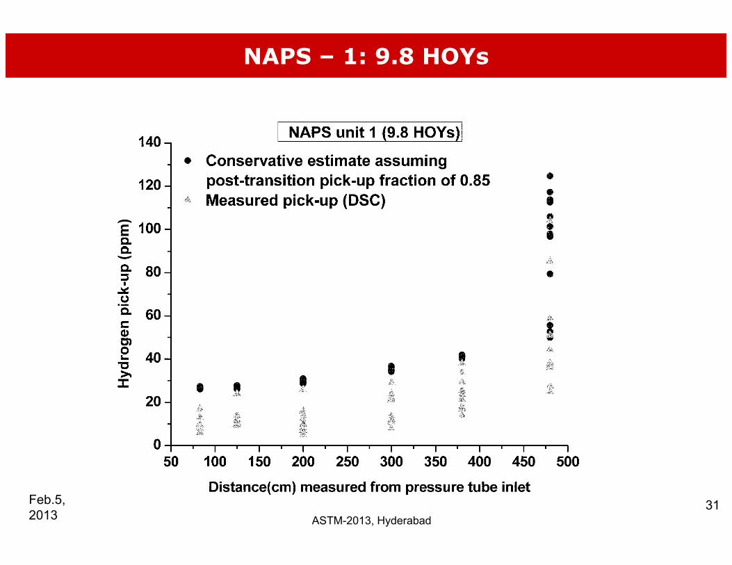
NAPS – 1: 9.8 HOYs
ASTM-2013, Hyderabad31Feb.5,
2013

NAPS – 1: 10.8 HOYs
ASTM-2013, Hyderabad32Feb.5,
2013

Conclusion
The model developed gives an upper bound envelop withThe model developed gives an upper bound envelop withreasonable conservatism.
It h l d i ifi tl i f ti f th it ithIt helped significantly in safe operation of the units withzircaloy-2 pressure tubes for ~12 years.
The last of the units was taken for retubing ~3 years back.
ASTM-2013, Hyderabad33Feb.5,
2013

ACKNOWLEDGEMENTSACKNOWLEDGEMENTS
• Shri J.N. Kayal, REDy ,• Shri B.B. Rupani• Shri K. Madhusoodnan, RED• All the Colleagues in PIED• All the Colleagues in PIED
ASTM-2013, Hyderabad34Feb.5,
2013

Thanks for kind attentionThanks for kind attention
ASTM-2013, Hyderabad 35Feb.5, 2013