Embed Size (px)
Citation preview
INEL-96/0317
Corrosion Experiments on Stainless Steels Used inDry Storage Canisters of Spent Nuclear Fuel
John M. RyskampJames P. Adams
Ernie M. FawPhilip A. Anderson
Published September 1996
Lockheed Martin Idaho Technologies CompanyIdaho National Engineering Laboratory
Idaho Falls, Idaho 83415
Prepared for theU.S. Department of Energy
Assistant Secretary for Environmental ManagementUnder DOE Idaho Operations Office
Contract DE-AC07-94ID13223
DISCLAIMER
This report was prepared as an account of work sponsored by an agency of theUnited States Government Neither the United States Government nor any agencythereof, nor any of their employees, makes any warranty, express or implied, orassumes any legal liability or responsibility for the accuracy, completeness, or use-fulness of any information, apparatus, product, or process disclosed, or representsthat its use would not infringe privately owned rights. Reference herein to any spe-cific commercial product, process, or service by trade name, trademark, manufac-turer, or otherwise does not necessarily constitute or imply its endorsement, recom-mendation, or favoring by the United States Government or any agency thereof.The views and opinions of authors expressed herein do not necessarily state orreflect those of the United States Government or any agency thereof.
DISCLAIMER
Portions of this document may be illegiblein electronic image products. Images areproduced from the best available originaldocument.
SUMMARY
The Idaho National Engineering Laboratory (INEL) currently stores a widevariety of spent nuclear fuel. Most of the fuel was originally intended to be storedunderwater for a short period of thermal cooling, then removed and reprocessed.However, due to the political constraints prohibiting reprocessing, the fuel has beenstored underwater for much longer than originally anticipated. During waterstorage, dust and airborne desert soil have entered the oldest INEL pool at the IdahoChemical Processing Plant (ICPP-603), accumulating on the fuel. Also, thealuminum fuel cladding or containment is corroding, compromising fuel storageconfigurations. Plans are now underway to move some of the more vulnerablealuminum plate type fuels and other fuel types into dry storage. Various types ofdamaged aluminum fuel from the ICPP-603 basin will be repackaged in stainlesssteel canisters. This canister material is then the barrier and could be susceptible tocorrosion damage from the interior and exterior environments.
Nonradioactive (cold) experiments have been set up in ICPP-1634, andradioactive (hot) experiments have been set up in the Irradiated Fuel Storage Facility(IFSF) at ICPP. The objective of these experiments is to provide information on theinteractions (corrosion) between the spent nuclear fuel currently stored at the ICPPand the dry storage canisters and containment materials in which this spent fuel willbe stored for the next several decades. This information will be used to help selectcanister materials that will retain structural integrity over this period withineconomic, criticality, and other constraints. The two purposes for Dual PurposeCanisters (DPCs) are for interim storage of spent nuclear fuel and for shipment toa final geological repository. Information on how corrosion products, sediments,and degraded spent nuclear fuel may corrode DPCs will be required before theDPCs will be allowed to be shipped out of the State of Idaho. The information willalso be required by the Nuclear Regulatory Commission (NRC) to support thelicensing of DPCs.
The rates of canister degradation expected to adversely affect the performanceof the container for a period of 50 to 100 years will be established. The corrosionexperiments will be used to determine the most likely degradation mechanisms thatcan affect the fuel canisters in a vented and/or sealed dry modular storage system.Nonradioactive experiments will provide benchmark data for comparisons with theradioactive experiments. These data can be used to determine if radioactively hotenvironments accelerate certain degradation mechanism. The IFSF at ICPP wasselected as the location for the radioactive experiments because the gamma doselevels are typical of those that will occur in DPCs.
Baseline values for the corrosion products to be introduced into the canistershave been established. Some important baseline values have been achieved throughinterfacing with results from a corroded fuel drying study (Lords et al 1996). Anappropriate test matrix has been established for the experiments to yield themaximum amount of data on the canister materials. The typical and worst
m
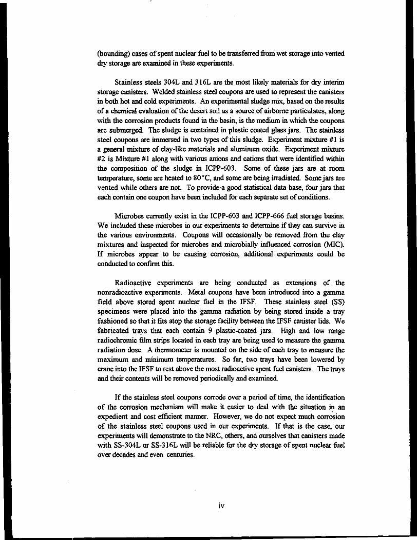
(bounding) cases of spent nuclear fuel to be transferred from wet storage into venteddry storage are examined in these experiments.
Stainless steels 304L and 316L are the most likely materials for dry interimstorage canisters. Welded stainless steel coupons are used to represent the canistersin both hot and cold experiments. An experimental sludge mix, based on the resultsof a chemical evaluation of the desert soil as a source of airborne particulates, alongwith the corrosion products found in the basin, is the medium in which the couponsare submerged. The sludge is contained in plastic coated glass jars. The stainlesssteel coupons are immersed in two types of this sludge. Experiment mixture #1 isa general mixture of clay-like materials and aluminum oxide. Experiment mixture#2 is Mixture #1 along with various anions and cations that were identified withinthe composition of the sludge in ICPP-603. Some of these jars are at roomtemperature, some are heated to 80 °C, and some are being irradiated. Some jars arevented while others are not. To provide a good statistical data base, four jars thateach contain one coupon have been included for each separate set of conditions.
Microbes currently exist in the ICPP-603 and ICPP-666 fuel storage basins.We included these microbes in our experiments to determine if they can survive inthe various environments. Coupons will occasionally be removed from the claymixtures and inspected for microbes and microbially influenced corrosion (MIC).If microbes appear to be causing corrosion, additional experiments could beconducted to confirm this.
Radioactive experiments are being conducted as extensions of thenonradioactive experiments. Metal coupons have been introduced into a gammafield above stored spent nuclear fuel in the IFSF. These stainless steel (SS)specimens were placed into the gamma radiation by being stored inside a trayfashioned so that it fits atop the storage facility between the IFSF canister lids. Wefabricated trays that each contain 9 plastic-coated jars. High and low rangeradiochromic film strips located in each tray are being used to measure the gammaradiation dose. A thermometer is mounted on the side of each tray to measure themaximum and minimum temperatures. So far, two trays have been lowered bycrane into the IFSF to rest above the most radioactive spent fuel canisters. The traysand their contents will be removed periodically and examined.
If the stainless steel coupons corrode over a period of time, the identificationof the corrosion mechanism will make it easier to deal with the situation in anexpedient and cost efficient manner. However, we do not expect much corrosionof the stainless steel coupons used in our experiments. If that is the case, ourexperiments will demonstrate to the NRC, others, and ourselves that canisters madewith SS-304L or SS-316L will be reliable for the dry storage of spent nuclear fuelover decades and even centuries.
IV
ACKNOWLEDGMENTS
Several people were instrumental in contributing to this work. We greatlyappreciate their support. Claude K. Kimball provided management oversight. WillE. Windes, Rebecca E. Lords, Ronald E. Mizia, Colleen V. Shelton-Davis, WilliamJ. Dirk, Kraig M. Wendt, and James H. Wolfram offered valuable advice on how toset up the experiments. Colleen V. Shelton-Davis also provided laboratory trainingand logistics help. Bruce W. Baird assisted with the Irradiated Fuel Storage Facility(IFSF) interface. Jeff L. Pappin supported the methods used to measure the gammadoses. Soon Sam Kim performed the MCNP calculation. Allyn W. Kyes conductedthe Unreviewed Safety Question screen. Henry J. Welland and Gregory K. Housleyperformed the detailed design of the corrosion tray. John M. Morgan fabricated thecorrosion trays. Douglas B. Ilium ordered some of the materials. DeAnnHammond typed this report. Finally, Claude K. Kimball, Will E. Windes, ColleenV. Shelton-Davis, and Robert C. Stump reviewed a draft version of this report andprovided many useful comments. We thank you all.

VI
CONTENTS
SUMMARY iii
ACKNOWLEDGMENTS v
ACRONYMS AND ABBREVIATIONS xi
1. EXPERIMENT OBJECTIVE 1
2. INTRODUCTION 2
3. EXPERIMENT OVERVIEW 7
4. EXPERIMENT REQUIREMENTS 8
5. EXPERIMENT ASSUMPTIONS 9
6. EXPERIMENT SETUP 10
6.1 Nonradioactive Experiments 12
6.2 Radioactive Experiments 12
7. PRE-EXPERIMENT COUPON MEASUREMENTS 24
8. TECHNICAL BASES FOR EXPERIMENT MIXTURE COMPOSITIONS 30
8.1 Experiment Mixture #1 30
8.2 Experiment Mixture #2 30
9. MAKEUP PROCEDURES FOR EXPERIMENT MIXTURES 32
9.1 Experiment Mixture #1 32
9.2 Experiment Mixture #2 32
10. IRRADIATED FUEL STORAGE FACILITY 34
11. REQUIREMENTS FOR CORROSION TRAY 38
12. DESIRED POST-EXPERIMENT COUPON MEASUREMENTS 39
REFERENCES 40
Appendix A—Corrosion Overview
vu
FIGURES
1. A piece of wet sludge shown making contact with weld area of SS canister in dry storage 3
2. Schematic of a stainless steel coupon immersed in a clay mixture contained in a pint jar 4
3. Photograph of a stainless steel coupon being immersed in simulated corrosion product number 1. . . . 5
4. The authors of this report are shown preparing the simulated corrosion product for thenonradioactive experiments 13
5. This photograph shows one of the corrosion trays and nine jars containing metal couponsdipped in either Mixture #1 or Mixture #2. After this photo was taken, each jar wasplaced in a partially open plastic bag and reinserted into the tray. Radiochromic film was thenadded before placement in the IFSF 18
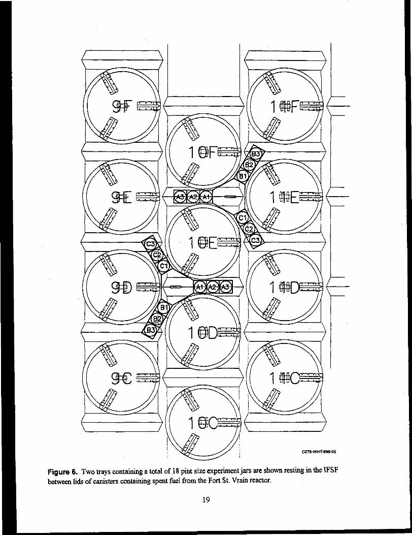
6. Two trays containing a total of 18 pint size experiment jars are shown resting in the IFSFbetween lids of canisters containing spent fuel from the Fort St Vrain reactor 19
7. This Close-up photograph shows a thermometer mounted on the side of a corrosion trayand three carbon steel coupons mounted on the top 20
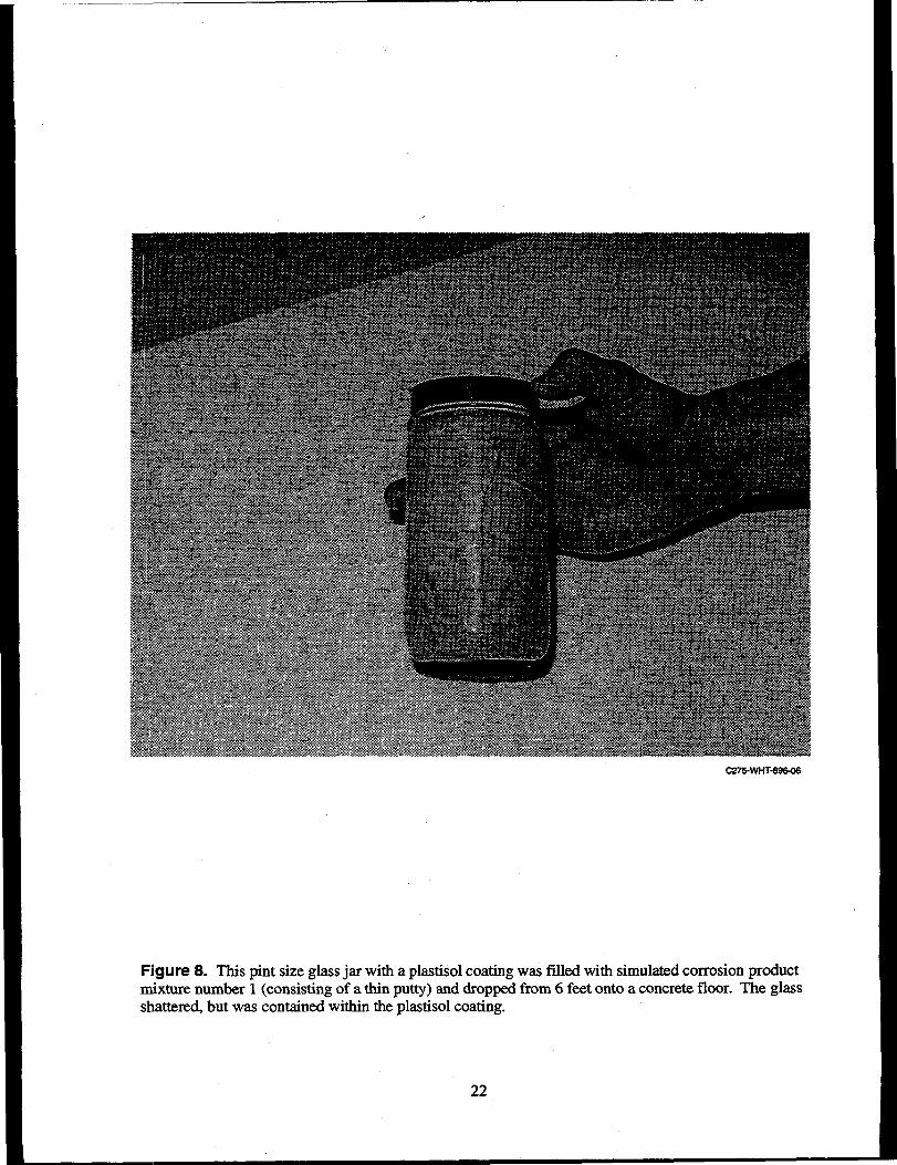
8. This pint size glass jar with a plastisol coating was filled with simulated corrosionproduct mixture number 1 (consisting of a thin putty) and dropped from 6 feet onto a concretefloor. The glass shattered, but was contained within the plastisol coating 22
9. Fuel storage rack and canister in the IFSF 36
10. Plan view of the IFSF showing the locations of the various types of spent nuclear fueland the two corrosion experiment trays 37
TABLES
1. Composition of simulated corrosion product mixture number 1 10
2. Composition of simulated corrosion product mixture number 2 (measured) 11
3. Testing Matrix for nonradioactive material interaction experiments 14
4. Coupon mass, surface area, environment, and location for the nonradioactive experiments 15
5. Testing matrix for radioactive material interaction experiments 17
6. Coupon mass, surface area, environment, and location in the radioactive experiments 17
7. Measured and calculated parameters of stainless steel 304L coupons 25
8. Measured and calculated parameters of stainless steel 316L coupons 27
9. Measured and calculated parameters of aluminum -6061 coupons 29
vui
10. Measured and calculated parameters of carbon steel 1020 coupons 29
11. IFSF fuel types and composition listing 35
IX

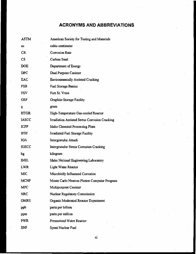
ACRONYMS AND ABBREVIATIONS
ASTM
cc
CR
CS
DOE
DPC
EAC
FSB
FSV
GSF
g
HTGR
IASCC
ICPP
IFSF
IGA
IGSCC
kg
INEL
LWR
MIC
MCNP
MPC
NRC
OMRE
ppb
ppm
PWR
SNF
American Society for Testing and Materials
cubic centimeter
Corrosion Rate
Carbon Steel
Department of Energy
Dual Purpose Canister
Environmentally Assisted Cracking
Fuel Storage Basins
Fort St. Vrain
Graphite Storage Facility
gram
High-Temperature Gas-cooled Reactor
Irradiation Assisted Stress Corrosion Cracking
Idaho Chemical Processing Plant
Irradiated Fuel Storage Facility
Intergranular Attack
Intergranular Stress Corrosion Cracking
kilogram
Idaho National Engineering Laboratory
Light Water Reactor
Microbially Influenced Corrosion
Monte Carlo Neutron Photon Computer Program
Multipurpose Canister
Nuclear Regulatory Commission
Organic Moderated Reactor Experiment
parts per billion
parts per million
Pressurized Water Reactor
Spent Nuclear Fuel
XI
ssTMI
USQ
uS
Stainless Steel
Three Mile Island
Unresolved Safety Question
Micro Siemens
Xll
Corrosion Experiments on Stainless Steels Usedin Dry Storage Canisters of Spent Nuclear Fuel
1. EXPERIMENT OBJECTIVE
The experiment objective is to provide information on the interactions (corrosion) between the spentnuclear fuel currently stored at the Idaho Chemical Processing Plant (ICPP) and the dry storage canistersand containment materials in which this spent fuel will be stored for the next several decades. Thisinformation will be used to help select canister materials that will retain structural integrity over thisperiod within economic, criticality, and other constraints. The two purposes for Dual Purpose Canisters(DPCs) are for interim storage of spent nuclear fuel and for shipment to a final geological wasterepository. Information on how corrosion products, sediments, and degraded spent nuclear fuel maycorrode DPCs will be required before the DPCs will be allowed to be shipped out of the State of Idaho.The information on the material interactions will be needed to confirm that the DPCs can be safely movedout of the State of Idaho. The information will also be required by the Nuclear Regulatory Commission(NRC) to support the licensing of DPCs.
Nonradioactive (cold) experiments have been set up in ICPP-1634, and radioactive (hot)experiments have been set up in the Irradiated Fuel Storage Facility (IFSF). The cold experiments willprovide benchmark data for comparisons with the hot experiments. This information is needed todetermine if radioactively hot environments accelerate certain degradation mechanisms. The hotexperiments have been designed to have minimal impact on IFSF operation.
2. INTRODUCTION
The Idaho National Engineering Laboratory (INEL) currently stores a wide variety of spent nuclearfuel. Most of the fuel was originally intended to be stored underwater for a short period of thermalcooling, then removed and reprocessed. However, due to the political constraints prohibitingreprocessing, the fuel has been stored underwater for much longer than originally anticipated. Duringwater storage, dust and airborne desert soil have entered the oldest INEL pool (ICPP-603), accumulatingon the fuel. Also, the aluminum fuel cladding or containment is corroding, compromising fuel storageconfigurations. Plans are now underway to move some of the more vulnerable aluminum plate type fuelsand other fuel types into dry storage. Various types of damaged aluminum fuel from the ICPP-603 basinwill be repackaged in canisters. This canister material is then the barrier and could be susceptible tocorrosion damage from the interior and exterior environments.
Observation of the ICPP-603 fuel storage basin environment and pool sludge indicates that theactual material on the fuel is a combination of components rather than pure aluminum corrosion product.Elemental analysis of corrosion on the aluminum coupon exposed to ICPP-603 basin water supports thisassessment. Airborne dust and silt blown into the ICPP-603 facility from the desert drifts and settles intothe open cooling channels in the fuel, forming a mixed deposit of sediment and aluminum oxide.
In the past the ICPP-603 basin experienced an algae bloom due to the desert dust, which severelyreduced water clarity. The algae problem was treated with a biocide, which aggravated the fuel claddingcorrosion problem due to the introduction of high chloride levels. The result was severe pitting ofaluminum fuel cladding, with complete penetration in some cases. The water chemistry also causedexcessive corrosion of carbon steel fuel storage devices such as storage hangers.
Residual moisture contained within hydrated corrosion/sediment products between the aluminumclad fuel plates may be difficult to remove using normal drying practices. Any remaining moisture maylead to additional degradation of the fuel and canister materials.
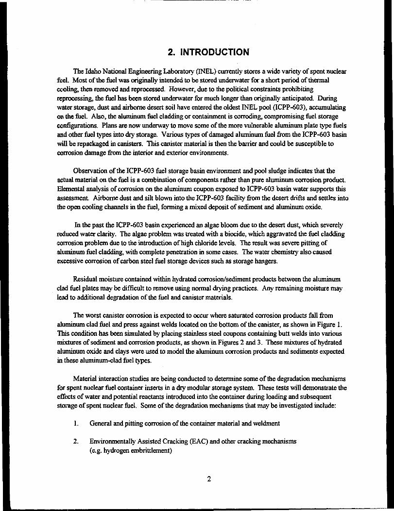
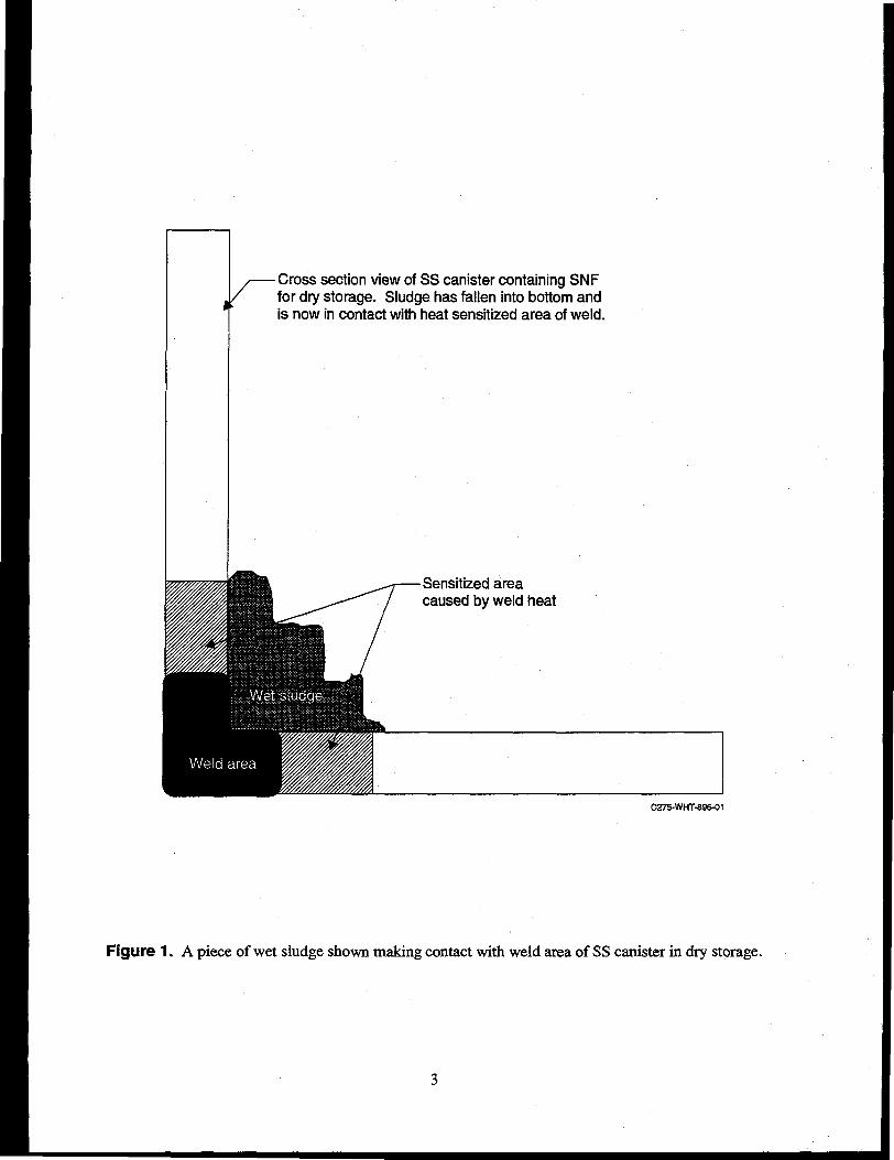
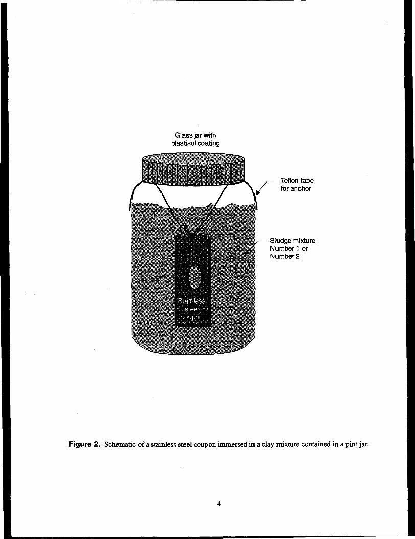
The worst canister corrosion is expected to occur where saturated corrosion products fall fromaluminum clad fuel and press against welds located on the bottom of the canister, as shown in Figure 1.This condition has been simulated by placing stainless steel coupons containing butt welds into variousmixtures of sediment and corrosion products, as shown in Figures 2 and 3. These mixtures of hydratedaluminum oxide and clays were used to model the aluminum corrosion products and sediments expectedin these aluminum-clad fuel types.
Material interaction studies are being conducted to determine some of the degradation mechanismsfor spent nuclear fuel container inserts in a dry modular storage system. These tests will demonstrate theeffects of water and potential reactants introduced into the container during loading and subsequentstorage of spent nuclear fuel. Some of the degradation mechanisms that may be investigated include:
1. General and pitting corrosion of the container material and weldment
2. Environmentally Assisted Cracking (EAC) and other cracking mechanisms(e.g. hydrogen embrittlement)
-Cross section view of SS canister containing SNFfor dry storage. Sludge has fallen into bottom andis now in contact with heat sensitized area of weld.
Sensitized areacaused by weld heat
C275-WHT-896-01
Figure 1. A piece of wet sludge shown making contact with weld area of SS canister in dry storage.
Glass jar withplastisol coating
Teflon tapefor anchor
Sludge mixtureNumber 1 orNumber 2
Figure 2. Schematic of a stainless steel coupon immersed in a clay mixture contained in a pint jar.
C275-WHT-896-03
Figure 3. Photograph of a stainless steel coupon being immersed in simulated corrosion productnumber 1.
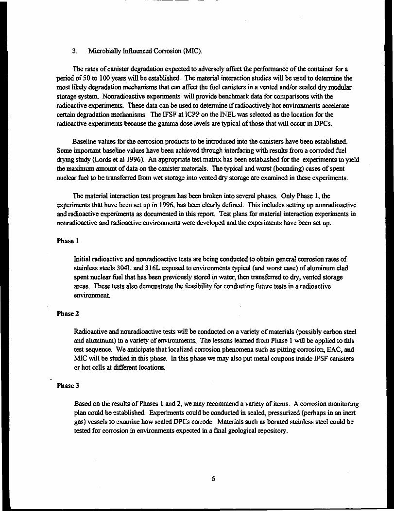
3. Microbially Influenced Corrosion (MIC).
The rates of canister degradation expected to adversely affect the performance of the container for aperiod of 50 to 100 years will be established. The material interaction studies will be used to determine themost likely degradation mechanisms that can affect the fuel canisters in a vented and/or sealed dry modularstorage system. Nonradioactive experiments will provide benchmark data for comparisons with theradioactive experiments. These data can be used to determine if radioactively hot environments acceleratecertain degradation mechanisms. The IFSF at ICPP on the INEL was selected as the location for theradioactive experiments because the gamma dose levels are typical of those that will occur in DPCs.
Baseline values for the corrosion products to be introduced into the canisters have been established.Some important baseline values have been achieved through interfacing with results from a corroded fueldrying study (Lords et al 1996). An appropriate test matrix has been established for the experiments to yieldthe maximum amount of data on the canister materials. The typical and worst (bounding) cases of spentnuclear fuel to be transferred from wet storage into vented dry storage are examined in these experiments.
The material interaction test program has been broken into several phases. Only Phase 1, theexperiments that have been set up in 1996, has been clearly defined. This includes setting up nonradioactiveand radioactive experiments as documented in this report. Test plans for material interaction experiments innonradioactive and radioactive environments were developed and the experiments have been set up.
Phase 1
Initial radioactive and nonradioactive tests are being conducted to obtain general corrosion rates ofstainless steels 304L and 316L exposed to environments typical (and worst case) of aluminum cladspent nuclear fuel that has been previously stored in water, then transferred to dry, vented storageareas. These tests also demonstrate the feasibility for conducting future tests in a radioactiveenvironment.
Phase 2
Radioactive and nonradioactive tests will be conducted on a variety of materials (possibly carbon steeland aluminum) in a variety of environments. The lessons learned from Phase 1 will be applied to thistest sequence. We anticipate that localized corrosion phenomena such as pitting corrosion, EAC, andMIC will be studied in this phase. In this phase we may also put metal coupons inside IFSF canistersor hot cells at different locations.
Phase 3
Based on the results of Phases 1 and 2, we may recommend a variety of items. A corrosion monitoringplan could be established. Experiments could be conducted in sealed, pressurized (perhaps in an inertgas) vessels to examine how sealed DPCs corrode. Materials such as borated stainless steel could betested for corrosion in environments expected in a final geological repository.
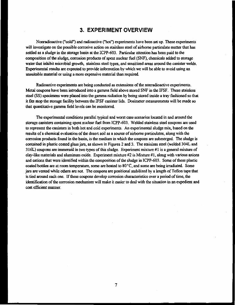
3. EXPERIMENT OVERVIEW
Nonradioactive ("cold") and radioactive ("hot") experiments have been set up. These experimentswill investigate on the possible corrosive action on stainless steel of airborne particulate matter that hassettled as a sludge in the storage basin at the ICPP-603. Particular attention has been paid to thecomposition of the sludge, corrosion products of spent nuclear fuel (SNF), chemicals added to storagewater that inhibit microbial growth, stainless steel types, and sensitized areas around the canister welds.Experimental results are expected to provide information by which we will be able to avoid using anunsuitable material or using a more expensive material than required.
Radioactive experiments are being conducted as extensions of the nonradioactive experiments.Metal coupons have been introduced into a gamma field above stored SNF in the IFSF. These stainlesssteel (SS) specimens were placed into the gamma radiation by being stored inside a tray fashioned so thatit fits atop the storage facility between the IFSF canister lids. Dosimeter measurements will be made sothat quantitative gamma field levels can be monitored.
The experimental conditions parallel typical and worst case scenarios located in and around thestorage canisters containing spent nuclear fuel from ICPP-603. Welded stainless steel coupons are usedto represent the canisters in both hot and cold experiments. An experimental sludge mix, based on theresults of a chemical evaluation of the desert soil as a source of airborne particulates, along with thecorrosion products found in the basin, is the medium in which the coupons are submerged. The sludge iscontained in plastic coated glass jars, as shown in Figures 2 and 3. The stainless steel (welded 304L and316L) coupons are immersed in two types of this sludge. Experiment mixture #1 is a general mixture ofclay-like materials and aluminum oxide. Experiment mixture #2 is Mixture #1, along with various anionsand cations that were identified within the composition of the sludge in ICPP-603. Some of these plasticcoated bottles are at room temperature, some are heated to 80°C, and some are being irradiated. Somejars are vented while others are not. The coupons are positional stabilized by a length of Teflon tape thatis tied around each one. If these coupons develop corrosion characteristics over a period of time, theidentification of the corrosion mechanism will make it easier to deal with the situation in an expedient andcost efficient manner.
4. EXPERIMENT REQUIREMENTS
1. Follow the American Society of Testing and Materials guide, ASTM G 1-88, "Standard Practice forPreparing, Cleaning, and Evaluating Corrosion Test Specimens," June, 1988.
2. Follow ASTM G 31-72, "Standard Practice for Laboratory Immersion Corrosion Testing ofMetals," 1985.
3. Follow C. V. Mclntyre letter CVM-17-91 to R. E. Mizia, "Updated Operating Instructions forCorrosion Experiments," November 19,1991.
4. Follow C. V. Shelton-Davis letter CVSD-15-92 to & C. Norby, "Run Plan for CorrosionExperiments," October 26,1992.
5. Fill out WINCO-5234X (10/94), "Waste Stream Approval Form," and receive approval.
6. Fill out WINCO-5630X (9/93), "Experimental Facility Safety & Hazard Checklist," and receiveapproval.
5. EXPERIMENT ASSUMPTIONS
1. Interactions with and corrosion of canister materials will be studied, not fuel integrity, degradation,or retrievability.
2. Interactions between different fuel types will not be examined.
3. Trace elements such as uranium and fission products will not be included in the experimentsbecause they are not expected to influence the corrosion rates.
4. Stainless steel coupons will be placed in a water saturated, simulated corrosion product clay torepresent the most corrosive condition (highest water content).
5. AD stainless steel coupons will be butt welded, then finished to a uniform 120 grit finish.
6. Adequate facilities are available at ICPP to conduct the radioactive experiments, and the facilitymanagers will allow these experiments to be conducted.
7. Additional funding will be required in 1997 and beyond to complete both the hot and coldexperiments.
S. Four coupons per experiment will provide adequate statistics for the coupon mass measurements(weight loss over time and, hence, corrosion rates).
9. Coupons can be reused within the same experiment after being cleaned of corrosion products andweighed.
6. EXPERIMENT SETUP
The highest priority canister materials being tested first are the following stainless steels (SS): 304Larid 316L. Only a few materials have been selected now for testing because of funding and scheduleconstraints. It is important to test the materials that have the highest probability for being used as storagecontainers of fuel transferred from the ICPP-603 pool. SS-304L is the material currently beingconsidered for fuel canning station canisters placed in the Irradiated Fuel Storage Facility at ICPP. SS-304L and SS-316L are the most likely materials for dry interim storage canisters over the next severaldecades. The current carbon steel canisters in the IFSF contain dry fuel that has not been in the ICPP-603pool; therefore, the canisters are not likely to corrode on the inside. Five carbon steel coupons werefastened on the outside of the two corrosion trays placed in the IFSF. This will help determine thecorrosion rate of carbon steel in the air within the IFSF. Aluminum may be used for some IFSF canisters,so four Al-6061 coupons were included in the radioactive experiments.
Each SS-304L coupon contains a butt weld made with weld rod material ER-308L. Each SS-316Lcoupon contains a butt weld made with weld rod material ER-316L. This will allow us to see if the weldsor heat affected zones corrode faster than the base coupon material. The coupons all have standard 120grit finishes placed after welding to allow smoother microscopic inspection of the coupons during post-tes>t evaluation.
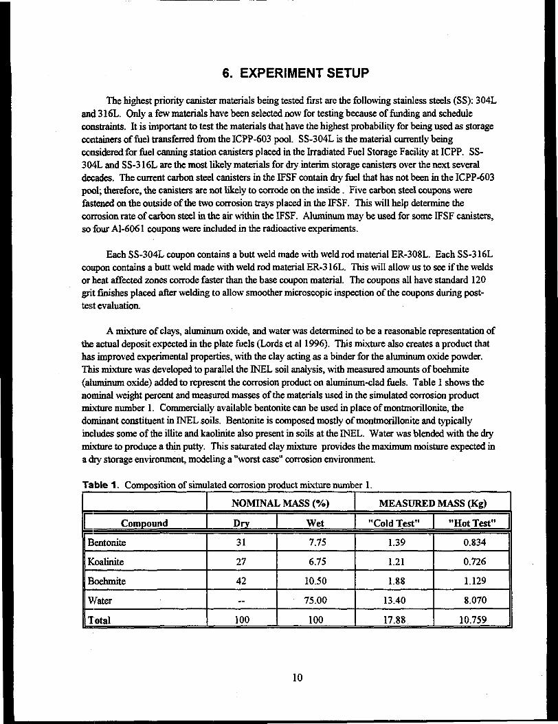
A mixture of clays, aluminum oxide, and water was determined to be a reasonable representation ofthe actual deposit expected in the plate fuels (Lords et al 1996). This mixture also creates a product thathas improved experimental properties, with the clay acting as a binder for the aluminum oxide powder.This mixture was developed to parallel the INEL soil analysis, with measured amounts of boehmite(aluminum oxide) added to represent the corrosion product on aluminum-clad fuels. Table 1 shows thenominal weight percent and measured masses of the materials used in the simulated corrosion productmixture number 1. Commercially available bentonite can be used in place of montmorillonite, thedominant constituent in INEL soils. Bentonite is composed mostly of montmorillonite and typicallyincludes some of the illite and kaolinite also present in soils at the INEL. Water was blended with the drymixture to produce a thin putty. This saturated clay mixture provides the maximum moisture expected ina dry storage environment, modeling a "worst case" corrosion environment.
Table 1. Composition of simulated corrosion product mixture number 1.
Compound
Bentonite
Koalinite
Boehmite
Water
Total
NOMINAL MASS (%)
Dry
31
27
42
—
100
Wet
7.75
6.75
10.50
75.00
100
MEASURED MASS (Kg)
"Cold Test"
1.39
1.21
1.88
13.40
17.88
"Hot Test"
0.834
0.726
1.129
8.070
10.759
10
To determine the appropriate amount of water to add, we made a batch of simulated corrosionproduct mixture number 1. The density of the dry mixture is about 0.66 g/cc. We placed this dry mixturein several different beakers, then added water to each beaker. The water content ranged from 60 to 80weight percent. These wet mixtures were then allowed to stand for 24 hours and firm up. A stainlesssteel coupon inserted in mixtures with water contents of 75% or less will remain standing. The couponswill fall over in mixtures with water content greater than 77.5%. All nonradioactive experiments use 75%water by weight to allow more water in the mixture (which may help produce higher corrosion rates).The density of this wet mixture is about 1.1 g/cc.
Two to three weeks after making these wet mixtures, we examined the beakers, which were leftopen. A large fraction of the water had evaporated, causing the clay mixtures to shrink. The clay pulledaway from the sides of the beakers in some locations. Therefore, ample clay mixture was added aboveand around the stainless steel coupons to ensure that the coupon remains mostly covered if the mixturedrysout.
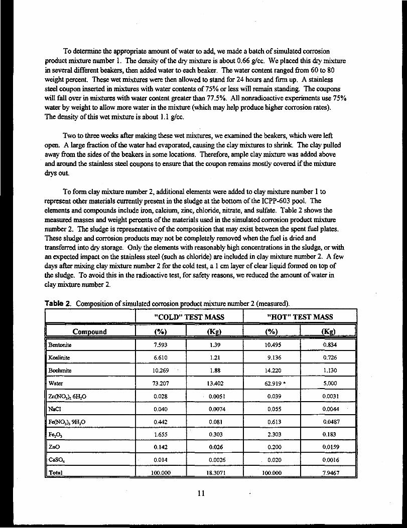
To form clay mixture number 2, additional elements were added to clay mixture number 1 torepresent other materials currently present in the sludge at the bottom of the ICPP-603 pool. Theelements and compounds include iron, calcium, zinc, chloride, nitrate, and sulfate. Table 2 shows themeasured masses and weight percents of the materials used in the simulated corrosion product mixturenumber 2. The sludge is representative of the composition that may exist between the spent fuel plates.These sludge and corrosion products may not be completely removed when the fuel is dried andtransferred into dry storage. Only the elements with reasonably high concentrations in the sludge, or withan expected impact on the stainless steel (such as chloride) are included in clay mixture number 2. A fewdays after mixing clay mixture number 2 for the cold test, a 1 cm layer of clear liquid formed on top ofthe sludge. To avoid this in the radioactive test, for safety reasons, we reduced the amount of water inclay mixture number 2.
Table 2. Composition of simulated corrosion product mixture number 2 (measured).
Compound
Bentonite
Koalinite
Boehmite
Water
Zn(NO3)j6HjO
NaCl
Fe(NO3)j9H2O
FeA
ZnO
CaSO4
Total
"COLD" TEST MASS
(%)
7.593
6.610
10.269
73.207
0.028
0.040
0.442
1.655
0.142
0.014
100.000
(Kg)
1.39
1.21
1.88
13.402
0.0051
0.0074
0.081
0.303
0.026
0.0026
18.3071
"HOT" TEST MASS
(%)
10.495
9.136
14.220
62.919 •
0.039
0.055
0.613
2.303
0.200
0.020
100.000
(Kg)
0.834
0.726
1.130
5.000
0.0031
0.0044
0.0487
0.183
0.0159
0.0016
7.9467
11
* The water content in the hot test is reduced in this mixture to achieve a thicker consistency so thatthe sludge will not run out of the jars if tipped over. The dry mass percents are the same for bothtests.
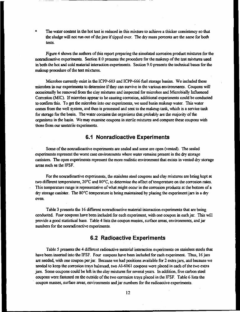
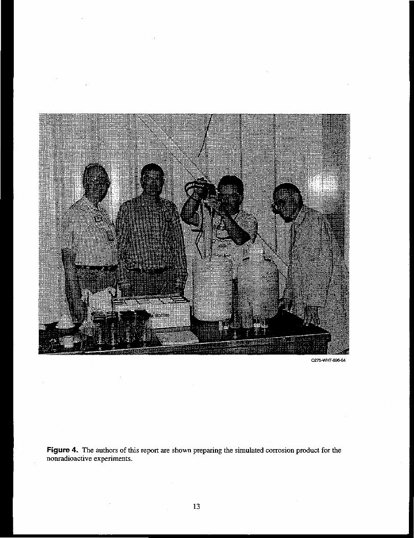
Figure 4 shows the authors of this report preparing the simulated corrosion product mixtures for thenonradioactive experiments. Section 8.0 presents the procedure for the makeup of the test mixtures usedin both the hot and cold material interaction experiments. Section 9.0 presents the technical bases for themakeup procedure of the test mixtures.
Microbes currently exist in the ICPP-603 and ICPP-666 fuel storage basins. We included thesemicrobes in our experiments to determine if they can survive in the various environments. Coupons willoccasionally be removed from the clay mixtures and inspected for microbes and Microbially InfluencedCorrosion (MIC). If microbes appear to be causing corrosion, additional experiments could be conductedto confirm this. To get the microbes into our experiments, we used basin makeup water. This watercomes from the well system, and then is processed and sent to the makeup tank, which is a service tankfor storage for the basin. The water contains the organisms that probably are the majority of theorganisms in the basin. We may examine coupons in sterile mixtures and compare these coupons withthose from our unsterile experiments.
6.1 Nonradioactive Experiments
Some of the nonradioactive experiments are sealed and some are open (vented). The sealedexperiments represent the worst case environments where water remains present in the dry storagecanisters. The open experiments represent the more realistic environment that exists in vented dry storageareas such as the IFSF.
For the nonradioactive experiments, the stainless steel coupons and clay mixtures are being kept attwo different temperatures, 20°C and 80°C, to determine the affect of temperature on the corrosion rates.This temperature range is representative of what might occur in the corrosion products at the bottom of adry storage canister. The 80°C temperature is being maintained by placing the experiment jars in a dryoven.
Table 3 presents the 16 different nonradioactive material interaction experiments that are beingconducted. Four coupons have been included for each experiment, with one coupon in each jar. This willprovide a good statistical base. Table 4 lists the coupon masses, surface areas, environments, and jarnumbers for the nonradioactive experiments.
6.2 Radioactive Experiments
Table 5 presents the 4 different radioactive material interaction experiments on stainless steels thathave been inserted into the IFSF. Four coupons have been included for each experiment. Thus, 16 jarsare needed, with one coupon per jar. Because we had positions available for 2 extra jars, and because weneeded to keep the corrosion trays balanced, two Al-6061 coupons were placed in each of the two extrajars. Some coupons could be left in the clay mixtures for several years. In addition, five carbon steelcoupons were fastened on the outside of the two corrosion trays placed in the IFSF. Table 6 lists thecoupon masses, surface areas, environments and jar numbers for the radioactive experiments.
12
C27S-WHT-896-04
Figure 4. The authors of this report are shown preparing the simulated corrosion product for thenonradioactive experiments.
13
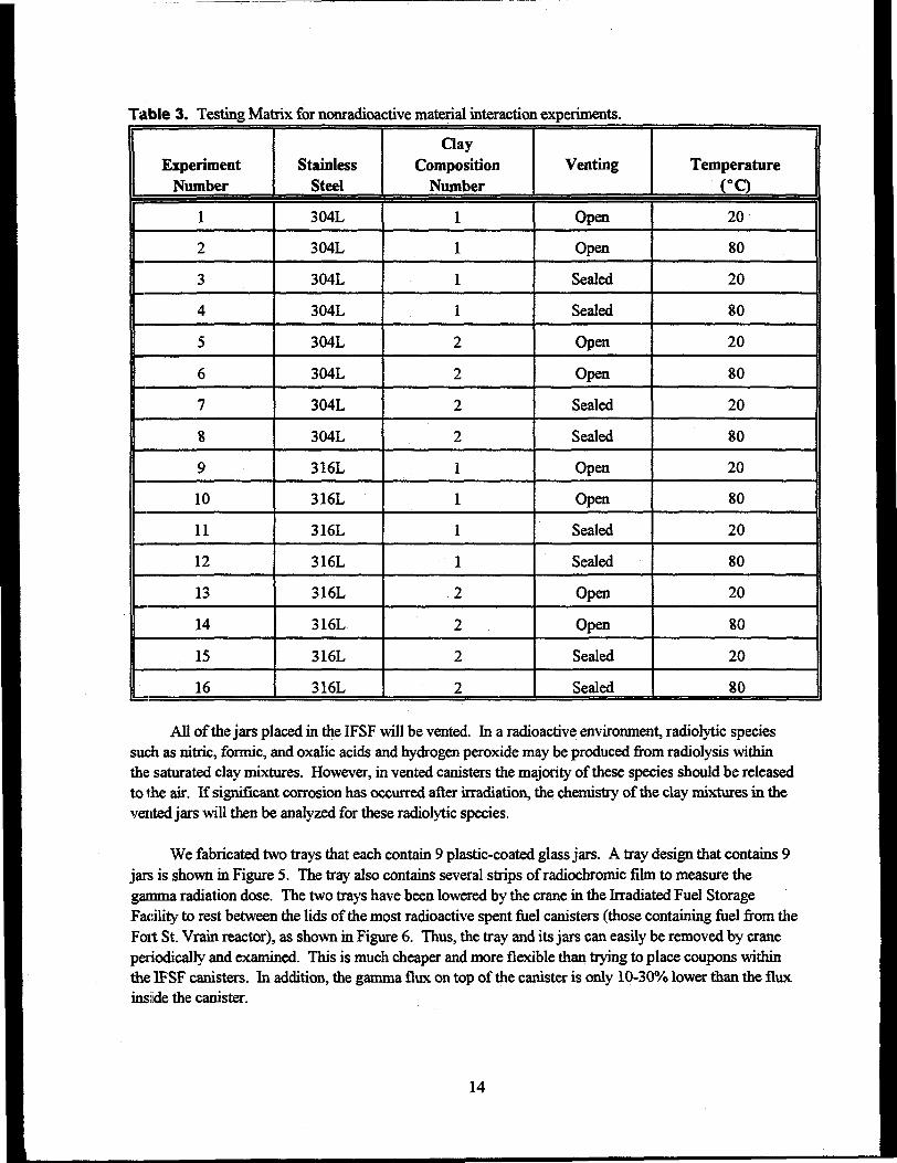
Table 3. Testing Matrix for nonradioactive material interaction experiments.
ExperimentNumber
1
2
3
4
5
6
7
8
9
10
11
12
13
14
15
16
StainlessSteel
304L
304L
304L
304L
304L
304L
304L
304L
316L
316L
316L
316L
316L
316L
316L
316L
ClayComposition
Number
1
1
1
1
2
2
2
2
1
1
1
1
2
2
2
2
Venting
Open
Open
Sealed
Sealed
Open
Open
Sealed
Sealed
Open
Open
Sealed
Sealed
Open
Open
Sealed
Sealed
Temperature( ° Q
20
80
20
80
20
80
20
80
20
80
20
80
20
80
20
80
All of the jars placed in the IFSF will be vented. In a radioactive environment, radiolytic speciessuch as nitric, formic, and oxalic acids and hydrogen peroxide may be produced from radiolysis withinthe saturated clay mixtures. However, in vented canisters the majority of these species should be releasedto the air. If significant corrosion has occurred after irradiation, the chemistry of the clay mixtures in thevented jars will then be analyzed for these radiolytic species.
We fabricated two trays that each contain 9 plastic-coated glass jars. A tray design that contains 9jars is shown in Figure 5. The tray also contains several strips of radiochromic film to measure thegamma radiation dose. The two trays have been lowered by the crane in the Irradiated Fuel StorageFacility to rest between the lids of the most radioactive spent fuel canisters (those containing fuel from theFort St. Vrain reactor), as shown in Figure 6. Thus, the tray and its jars can easily be removed by craneperiodically and examined. This is much cheaper and more flexible than trying to place coupons withinthe IFSF canisters. In addition, the gamma flux on top of the canister is only 10-30% lower than the fluxinside the canister.
14
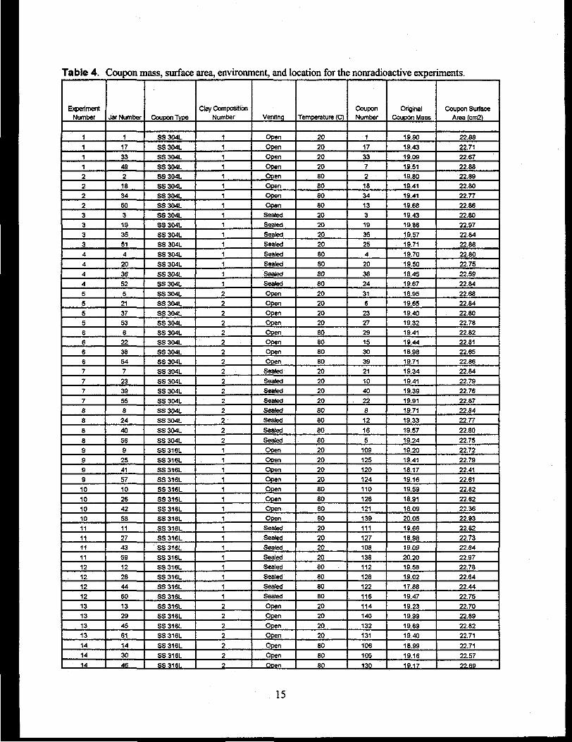
Table 4.
Experiment
Number
1
1
1
12
22
233
334
4
44
55
556666
7
7
7
7
88
8
89
99
910
10101011
1111
1112
1212
121313
1313
1414
14
Coupon mass, surface area, environment, and location for the nonradioactive experiments.
Jar Number
1
17
334921834
50
3193551
4
20
3652
52137
536223854
7
2339
55
824
40
569
2541
5710
26
425811
2743
5912
284460
1329
4561
14
3046
Coupon Type
SS304L
SS304L
SS304L
SS304LSS304LSS304L
SS304L
SS304LSS304LSS304LSS304LSS304LSS304L
SS304L
SS304LSS 304L
SS304LSS304LSS 304L
SS 304LSS304LSS304LSS304LSS 304L
SS 304L
SS 304LSS 304L
SS 304L
SS304LSS 304L
SS 304L
SS 304LSS 316LSS 316LSS 316L
SS 316LSS 316L
SS 316LSS 316LSS 316LSS 316L
SS 316LSS 316L
SS 316LSS 316L
SS316LSS 316LSS316L
SS 316LSS316L
SS316LSS316L
SS316L
SS316LSS 316L
Clay CompositionNumber
1
1
1
11
11
11
1
1
1
1
11
1
22
22222
22
2
22
2
2
2
21
1
11
1
11
1
1
1
11
1
1
11
22
2
2
2
22
Ventinq
Open
Open
Open
OpenOpenOpenOpen
OpenSealedSealed
SealedSealed
Sealed
Sealed
SealedSealedOpen
OpenOpen
OpenOpenOpenOpenOpen
Sealed
SealedSealed
Sealed
Sealed
Sealed
Sealed
SealedOpenOpen
OpenOpenOpen
OpenOpenOpen
Sealed
SealedSealed
SealedSealed
SealedSealedSealed
OpenOpen
Open
Open
Open
OpenOpen
Temperature (O
20
2020
20808080
802020
2020
80
80
8080
2020
202080808080
20
2020
20
8080
80
80
2020
202080
80808020
2020
2080
808080
2020
2020
808080
CouponNumber
1
17
33
721834
133
193525
4
20
3624
316
2327
291530
39
21
1040
228
12
16
5109
125120124
110
126121139111
127108
138112
128122116114
140
132131
106
105130
OriginalCoupon Mass
19.90
19.4319.09
19.5119.8019.4119.41
19.6819.4319.86
19.5719.71
19.70
19.50
18.4519.67
18.9519.65
19.4019.3219.4119.44
18.9819.71
19.34
19.41
19.3919.9119.71
19.33
19.57
19.24
19.2019.41
18.17
19.1619.5918.91
18.0920.0519.66
18.9819.09
20.2019.58
19.0217.88
19.47
19.2319.99
19.69
19.40
18.99
19.161917
Coupon SurfaceArea (em2)
22.88
22.71
22.6722.8822.8922.8022.7722.8622.80
22.9722.8422.88
22.8022.75
22.5922.84
22.6822.84
22.8022.7822.8222.8122.6522.8622.84
22.79
22.7622.87
22.8422.77
22.80
22.75
22.7222.7922.41
22.6122.82
22.6222.3622.9322.82
22.7322.64
22.9722.78
22.6422.44
22.75
22.7022.89
22.8222.71
22.71
22.57
22 69
15
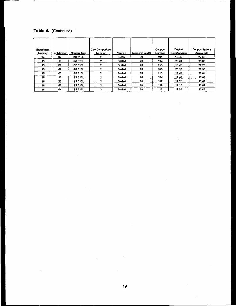
Table 4. (Continued)
ExperimentNumber
14
15
15
15
15161616
16
Jar Number62
1531
47
63
163248
64
Coupon TypeSS316L
SS316LSS316L
SS316L
SS316LSS 316L
SS316LSS316L
SS316L
Clay CompositionNumber
2
2
2
22
2
22
2
Venting
Open
SealedSealed
Sealed
SealedSealed
SealedSealed
Sealed
Temperature (O
eo20
20
202080
8080
80
CouponNumber
101
134118
136115104107
129
113
OriginalCoupon Mass
19.36
20.24
19.42
20.13
19.4519.48
19.2519.15
19.63
Coupon SurfaceArea (cm2)
22.86
23.00
22.7822.95
22.8422.8222.6822.67
22.85
16
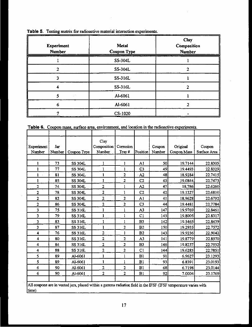
Table 5. Testing matrix for radioactive material interaction experiments.
Experiment
Number
1
2
3
4
5
6
7
Metal
Coupon Type
SS-304L
SS-304L
SS-316L
SS-316L
Al-6061
Al-6061
CS-1020
Clay
Composition
Number
1
2
1
2
1
2
.
Table 6. Coupon mass, surface area, environment, and location in the radioactive experiments.
ExperimentNumber
111
1
2
2
2233
3344
44
5
5
66
JarNumber
7377
8185
74
78
828675
79838776
8084
888989
9090
Coupon Type
SS 304LSS304L
SS304LSS304L
SS304L
SS 304L
SS 304LSS 304LSS316LSS316L
SS316LSS316LSS316L
SS316L
SS316LSS316L
Al-6061Al-6061
Al-6061Al-6061
ClayComposition
Number
1111
2
2
2
2111122
2211
22
CorrosionTray#
11
22
1
1
2211
121
2
2211
22
Position
AlC3
A2C2
A2
C2
AlC3A3Cl
B3B2B2
A3B3Cl
Bl
BlBlBl
CouponNumber
5049
484547
42
4144
147
145
142150143
141
146144
91
93
6892
OriginalCoupon Mass
19.7144
19.449318.928419.0844
18.786
19.1227
18.962819.448119.976919.8005
19.546519.293519.9236
19.877919.8237
19.62836.9627
6.8391
6.71987.0004
CouponSurface Area
22.830522.8329
22.741522.747322.6260
22.6810
22.679222.778422.846122.8317
22.843922.757222.9042
22.8970
22.795222.7851
23.1293
23.019323.014423.1769
All coupons are in vented jars, placed within a gamma radiation field in the IFSF (IFSF temperature varies withtime)
17
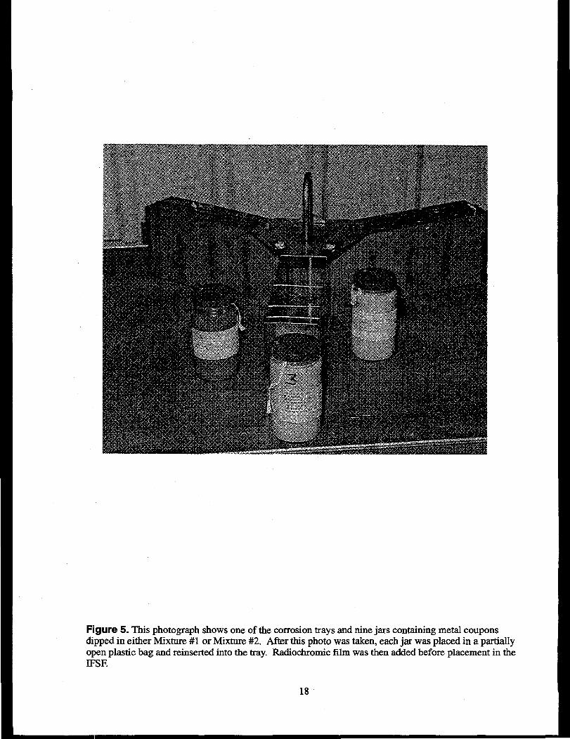
Figure 5. This photograph shows one of the corrosion trays and nine jars containing metal couponsdipped in either Mixture #1 or Mixture #2. After this photo was taken, each jar was placed in a partiallyopen plastic bag and reinserted into the tray. Radiochromic film was then added before placement in theIFSF.
18
C275-WHT-896-05
Figure 6. Two trays containing a total of 18 pint size experiment jars are shown resting in the IFSFbetween lids of canisters containing spent fuel from the Fort St. Vrain reactor.
19
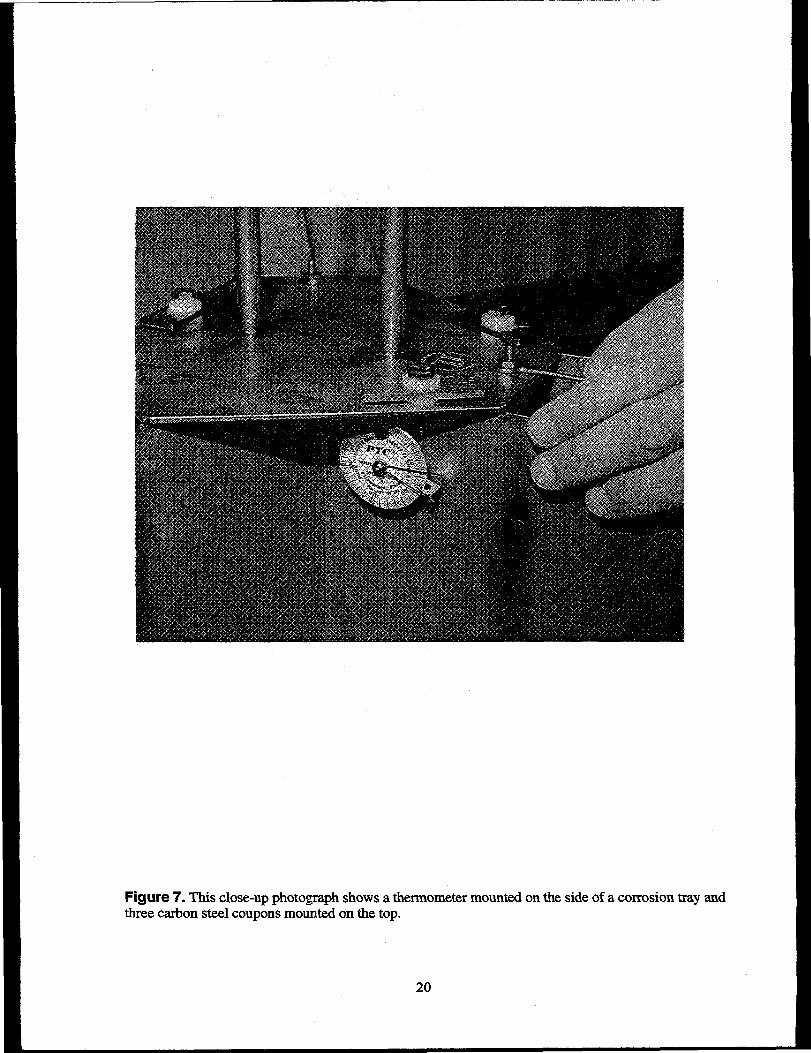
Figure 7. This close-up photograph shows a thermometer mounted on the side of a corrosion tray andthree carbon steel coupons mounted on the top.
20
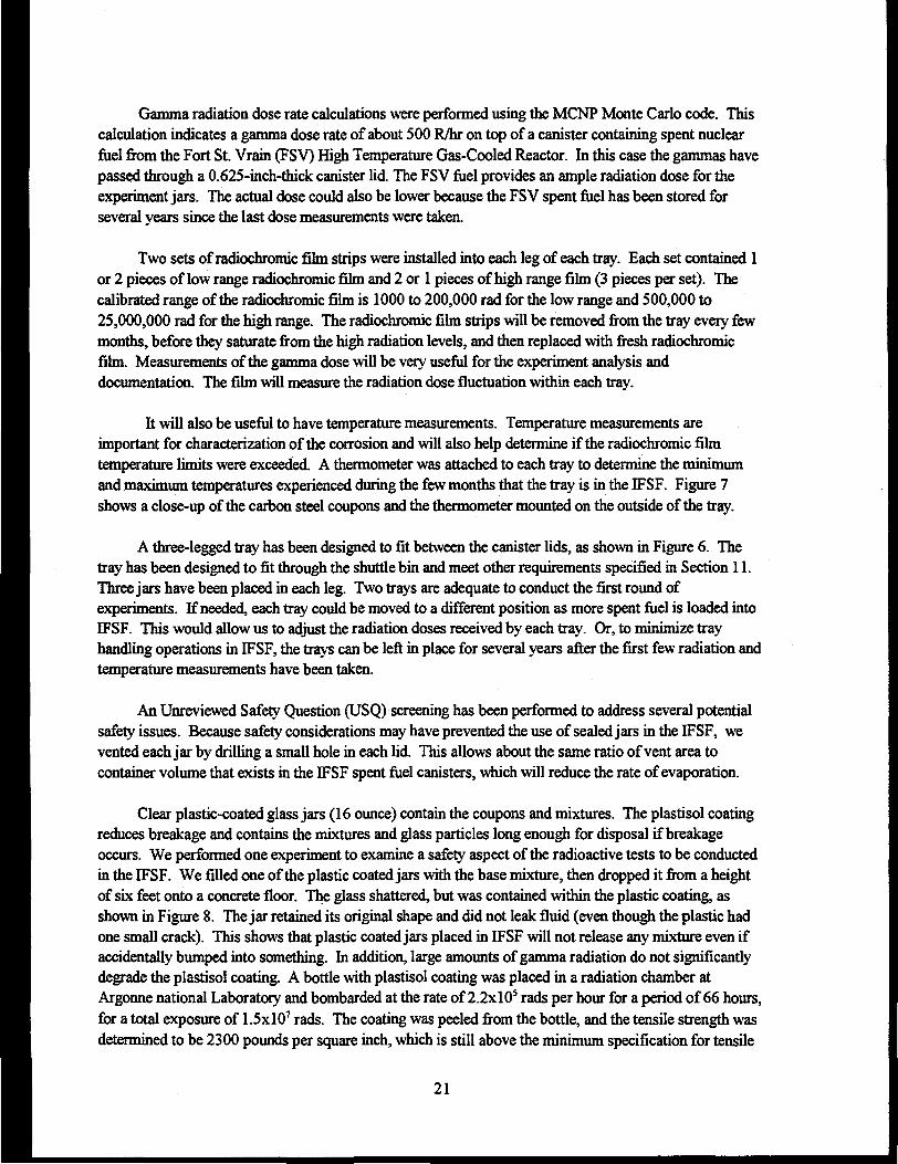
Gamma radiation dose rate calculations were performed using the MCNP Monte Carlo code. Thiscalculation indicates a gamma dose rate of about 500 R/hr on top of a canister containing spent nuclearfuel from the Fort St. Vrain (FSV) High Temperature Gas-Cooled Reactor. In this case the gammas havepassed through a 0.625-inch-thick canister lid. The FSV fuel provides an ample radiation dose for theexperiment jars. The actual dose could also be lower because the FSV spent fuel has been stored forseveral years since the last dose measurements were taken.
Two sets of radiochromic film strips were installed into each leg of each tray. Each set contained 1or 2 pieces of low range radiochromic film and 2 or 1 pieces of high range film (3 pieces per set). Thecalibrated range of the radiochromic film is 1000 to 200,000 rad for the low range and 500,000 to25,000,000 rad for the high range. The radiochromic film strips will be removed from the tray every fewmonths, before they saturate from the high radiation levels, and then replaced with fresh radiochromicfilm. Measurements of the gamma dose will be very useful for the experiment analysis anddocumentation. The film will measure the radiation dose fluctuation within each tray.
It will also be useful to have temperature measurements. Temperature measurements areimportant for characterization of the corrosion and will also help determine if the radiochromic filmtemperature limits were exceeded. A thermometer was attached to each tray to determine the minimumand maximum temperatures experienced during the few months that the tray is in the IFSF. Figure 7shows a close-up of the carbon steel coupons and the thermometer mounted on the outside of the tray.
A three-legged tray has been designed to fit between the canister lids, as shown in Figure 6. Thetray has been designed to fit through the shuttle bin and meet other requirements specified in Section 11.Three jars have been placed in each leg. Two trays are adequate to conduct the first round ofexperiments. If needed, each tray could be moved to a different position as more spent fuel is loaded intoIFSF. This would allow us to adjust the radiation doses received by each tray. Or, to minimize trayhandling operations in IFSF, the trays can be left in place for several years after the first few radiation andtemperature measurements have been taken.
An Unreviewed Safety Question (USQ) screening has been performed to address several potentialsafely issues. Because safety considerations may have prevented the use of sealed jars in the IFSF, wevented each jar by drilling a small hole in each lid. This allows about the same ratio of vent area tocontainer volume that exists in the IFSF spent fuel canisters, which will reduce the rate of evaporation.
Clear plastic-coated glass jars (16 ounce) contain the coupons and mixtures. The plastisol coatingreduces breakage and contains the mixtures and glass particles long enough for disposal if breakageoccurs. We performed one experiment to examine a safety aspect of the radioactive tests to be conductedin the IFSF. We filled one of the plastic coated jars with the base mixture, then dropped it from a heightof six feet onto a concrete floor. The glass shattered, but was contained within the plastic coating, asshown in Figure 8. The jar retained its original shape and did not leak fluid (even though the plastic hadone small crack). This shows that plastic coated jars placed in IFSF will not release any mixture even ifaccidentally bumped into something. In addition, large amounts of gamma radiation do not significantlydegrade the plastisol coating. A bottle with plastisol coating was placed in a radiation chamber atArgonne national Laboratory and bombarded at the rate of 2.2xlO5 rads per hour for a period of 66 hours,for a total exposure of 1.5xlO7 rads. The coating was peeled from the bottle, and the tensile strength wasdetermined to be 2300 pounds per square inch, which is still above the minimum specification for tensile
21
CZ75-WHT-896-06
Figure 8. This pint size glass jar with a plastisol coating was filled with simulated corrosion productmixture number 1 (consisting of a thin putty) and dropped from 6 feet onto a concrete floor. The glassshattered, but was contained within the plastisol coating.
22
strength. Therefore, the plastical coating will still function successfully in the event of jar breakage, evenafter 3 to 4 years in the IFSF, and probably after 10 years.
Placement of the stainless steel coupons in trays resting outside and above the canisters, aspresented, here has the following advantages over placement of steel coupons inside the IFSF canisters:
1. Much easier and less costly to design, insert, and retrieve
2. Measured radiation doses and temperatures
3. Fewer safety issues because the fuel inside the canisters will not be affected
4. Easier setup and installation because the entire trays of experiments could be prepared ahead oftime in a nonradioactive laboratory.
In later phases of this project we wish to also put metal coupons (dipped in Mixtures #1 and #2)inside the vented IFSF canisters. The vented canisters are dried to an undetermined level and then placedin an uncontrolled humidity environment. By placing the samples (coupons and sludge) into the IFSFcanisters before drying, we can determine the moisture content of the sludge after drying and storage forseveral years. Also, the corrosion experiments will then occur in environments (humidity, temperature,radiation) that more closely resemble what the actual fuel canisters experience.
23
7. PRE-EXPERIMENT COUPON MEASUREMENTS
Metal coupons were prepared and measured following the first requirement in Section 4.0. Thewidth, length, thickness, and hole inner diameter were measured for each coupon. Two width and twothickness measurements for each coupon were used to obtain an average width and an average thicknessfor each coupon. The coupons were all scrubbed, rinsed in water, dried with pressurized air, rinsed in anacetone bath, dried again with pressurized air, then dried further in an oven. Subsequent to the initialscrubbing and rinse, we handled the coupons with tongs and gloved hands to avoid contamination. Weweighed each coupon to the nearest 0.000 lg. From these measurements, we calculated the area, volume,and density of each coupon. For any values that deviated significantly from the mean, we remeasured thecoupon. Each coupon was inspected, and one coupon with previous corrosion was rejected. Measuredand calculated parameters for each coupon are presented in Table 7 for SS-304L, Table 8 for SS-316L,Table 9 for Al-6061, and Table 10 for carbon steel-1020.
24
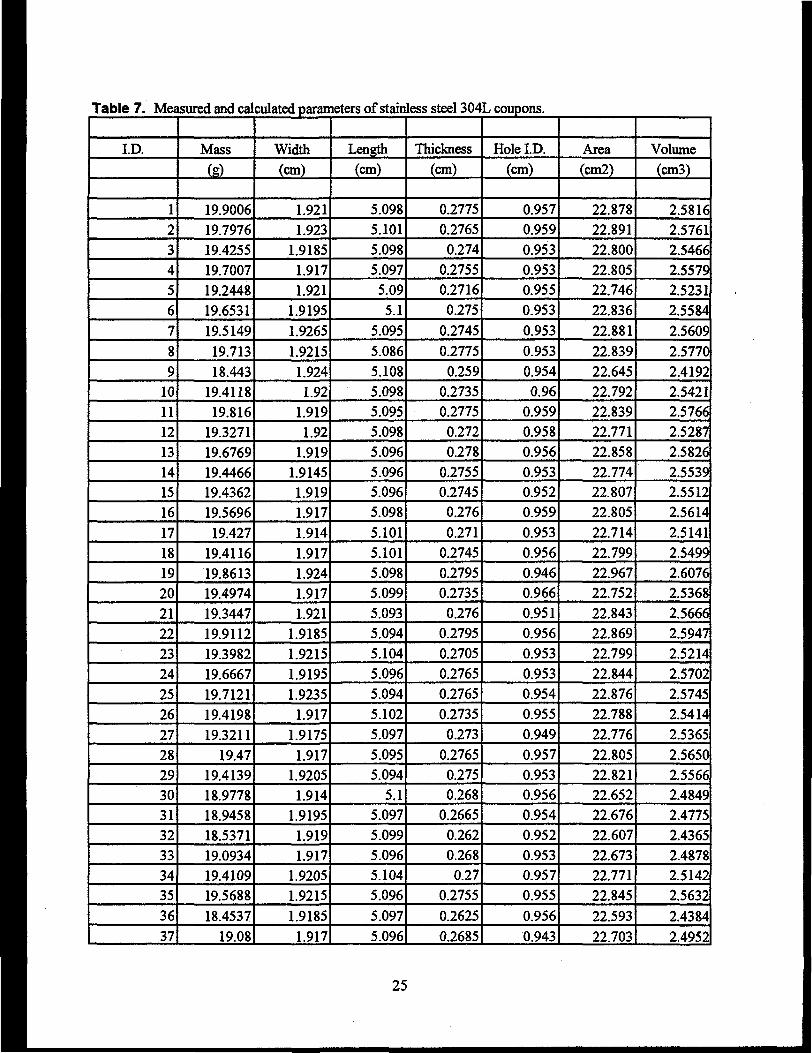
Table 7. Measured and calculated parameters of stainless steel 304L coupons.
ID.
1
234
5678
910111213141516
17
181920
2122
2324
252627
2829303132333435
3637
Mass
(g)
19.900619.7976
19.425519.700719.244819.6531
19.5149
19.713
18.44319.4118
19.81619.327119.676919.446619.436219.5696
19.427
19.411619.861319.4974
19.344719.911219.398219.6667
19.712119.4198
19.321119.47
19.413918.977818.945818.537119.093419.4109
19.5688
18.4537
19.08
Width(cm)
1.9211.923
1.91851.917
1.9211.9195
1.9265
1.92151.924
1.921.919
1.92
1.9191.91451.9191.917
1.914
1.9171.9241.917
1.9211.91851.9215
1.91951.9235
1.917
1.9175
1.9171.92051.914
1.91951.9191.917
1.92051.9215
1.91851.917
Length
(cm)
5.0985.1015.0985.097
5.095.1
5.095
5.086
5.1085.0985.0955.0985.0965.0965.0965.098
5.101
5.1015.0985.099
5.0935.0945.104
5.0965.094
5.1025.097
5.0955.094
5.15.0975.0995.0965.104
5.096
5.097
5.096
Thickness(cm)
0.27750.27650.274
0.2755
0.27160.275
0.2745
0.2775
0.2590.27350.2775
0.2720.278
0.27550.27450.276
0.271
0.27450.27950.2735
0.2760.27950.2705
0.2765
0.27650.2735
0.273
0.27650.2750.268
0.26650.2620.2680.27
0.2755
0.2625
0.2685
Hole ID.
(cm)
0.9570.9590.9530.9530.9550.953
0.953
0.953
0.9540.96
0.9590.9580.9560.9530.9520.959
0.953
0.9560.9460.966
0.9510.9560.9530.9530.954
0.9550.949
0.9570.9530.9560.9540.9520.9530.957
0.955
0.956
0.943
Area
(cm2)
22.878
22.89122.80022.805
22.74622.836
22.881
22.839
22.64522.79222.83922.77122.85822.77422.80722.805
22.714
22.79922.96722.752
22.84322.86922.79922.844
22.87622.788
22.776
22.80522.82122.652
22.67622.60722.67322.77122.845
22.593
22.703
Volume(cm3)
2.58162.57612.54662.55792.52312.5584
2.5609
2.5770
2.41922.54212.57662.5287
2.58262.55392.55122.5614
2.51412.54992.60762.53682.56662.59472.5214
2.57022.57452.5414
2.5365
2.56502.55662.48492.47752.43652.48782.5142
2.5632
2.4384
2.4952
25
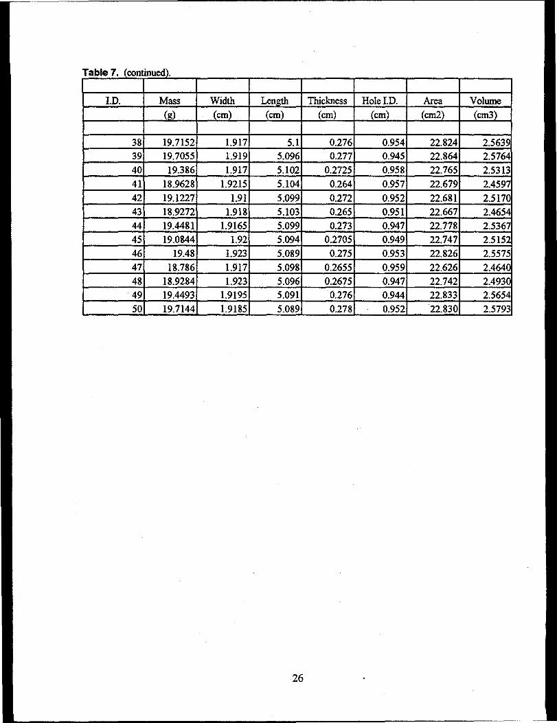
Table 7. (continued).
I.D.
38394041424344454647484950
Mass
(g)
19.715219.705519.386
18.962819.122718.927219.448119.0844
19.4818.786
18.928419.449319.7144
Width(cm)
1.9171.9191.917
1.92151.911.9181.91651.921.9231.9171.9231.91951.9185
Length(cm)
5.15.0965.1025.104
5.0995.1035.0995.0945.0895.0985.0965.0915.089
Thickness(cm)
0.2760.277
0.27250.2640.2720.2650.273
0.27050.275
0.26550.26750.2760.278
Hole I.D.(cm)
0.9540.9450.9580.9570.9520.9510.9470.9490.9530.9590.9470.9440.952
Area(cm2)
22.82422.86422.76522.67922.68122.66722.77822.74722.82622.62622.74222.83322.830
Volume(cm3)
2.56392.57642.53132.45972.51702.46542.53672.51522.55752.46402.49302.56542.5793
26
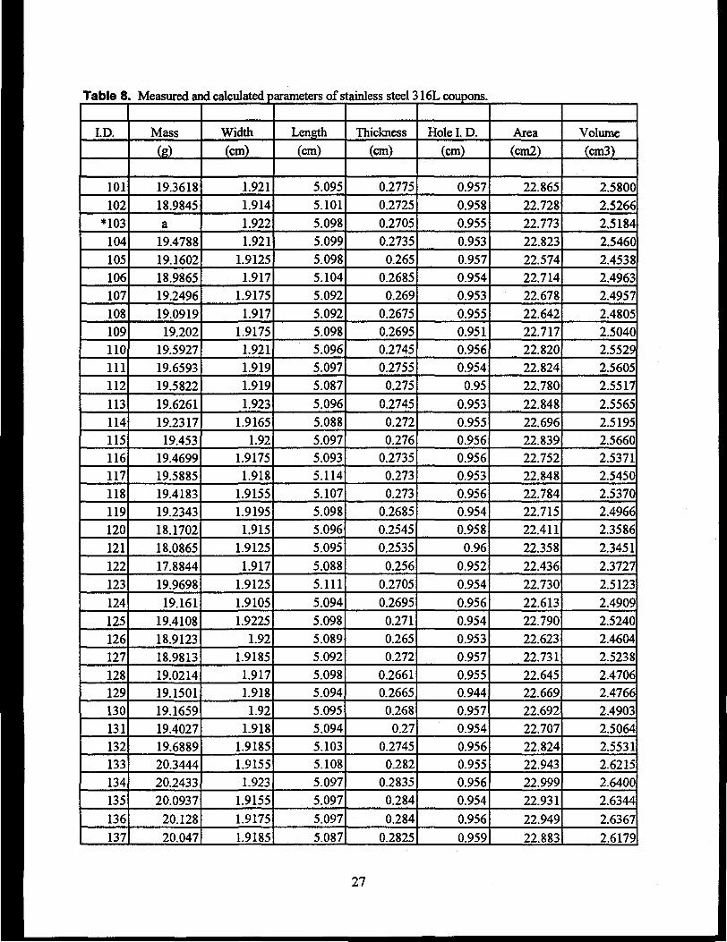
Table 8
I.D.
101
102*103
104105
106107
108
109110111112113114115116117
118119120121
122
123
124
125126127
128129130
131132133
134135
136
137
. Measured and calculated parameters of stainless steel 316L coupons.
Mass
(g)
19.3618
18.9845
a19.478819.160218.986519.2496
19.0919
19.20219.592719.6593
19.5822
19.626119.2317
19.45319.469919.588519.418319.2343
18.170218.086517.8844
19.9698
19.161
19.410818.912318.981319.021419.150119.165919.402719.688920.3444
20.243320.0937
20.128
20.047
Width
(cm)
1.9211.914
1.9221.921
1.91251.917
1.9175
1.9171.91751.9211.9191.919
1.9231.9165
1.921.91751.918
1.91551.9195
1.9151.9125
1.917
1.9125
1.9105
1.92251.92
1.9185
1.9171.9181.92
1.9181.91851.9155
1.9231.9155
1.9175
1.9185
Length
(cm)
5.095
5.101
5.0985.0995.0985.1045.092
5.0925.0985.0965.097
5.087
5.0965.0885.0975.0935.1145.107
5.0985.0965.095
5.088
5.1115.094
5.0985.0895.092
5.0985.0945.0955.0945.1035.1085.097
5.097
5.097
5.087
Thickness
(cm)
0.2775
0.2725
0.27050.2735
0.2650.2685
0.269
0.2675
0.26950.27450.2755
0.275
0.27450.2720.276
0.27350.273
0.2730.26850.2545
0.2535
0.256
0.2705
0.26950.271
0.2650.272
0.26610.26650.268
0.270.2745
0.2820.28350.284
0.284
0.2825
Hole I. D.
(cm)
0.957
0.958
0.955
0.9530.9570.9540.9530.955
0.9510.9560.954
0.95
0.953
0.9550.9560.9560.953
0.9560.9540.958
0.960.952
0.954
0.956
0.9540.9530.957
0.9550.9440.9570.9540.9560.9550.956
0.954
0.956
0.959
Area
(cm2)
22.865
22.728
22.77322.82322.57422.71422.678
22.64222.71722.82022.824
22.780
22.848
22.69622.83922.75222.848
22.78422.71522.411
22.358
22.43622.730
22.613
22.79022.62322.731
22.64522.66922.69222.70722.82422.94322.999
22.931
22.949
22.883
Volume(cm3)
2.5800
2.5266
2.51842.54602.45382.49632.4957
2.4805
2.50402.55292.5605
2.5517
2.55652.51952.56602.53712.54502.53702.49662.3586
2.34512.3727
2.5123
2.4909
2.52402.46042.52382.47062.47662.49032.50642.55312.62152.6400
2.6344
2.6367
2.6179
27
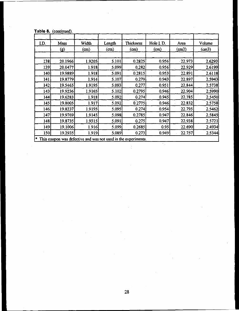
Table 8.
I.D.
138
139
140141
142143144145146147
148149
150
(continued).
Mass
(g)
20.1966
20.047719.9889
19.8779
19.546519.923619.628319.800519.8237
19.976919.8735
19.100619.2935
Width
(cm)
1.9205
1.918
1.9181.914
1.91951.9165
1.9181.917
1.91951.9145
1.93151.916
1.919
Length(cm)
5.101
5.099
5.0915.107
5.0935.1025.0925.0925.095
5.0985.091
5.0995.089
Thickness(cm)
0.2825
0.2820.28150.279
0.2770.2795
0.2740.27750.274
0.27850.275
0.26850.273
Hole I D .
(cm)
0.9560.956
0.953
0.9430.951
0.9460.9450.9460.954
0.947
0.947
0.95
0.949
Area(cm2)
22.973
22.929
22.89122.897
22.84422.90422.78522.832
22.79522.84622.938
22.69022.757
Volume(cm3)
2.6293
2.6199
2.61182.5943
2.57382.59902.54502.57582.54622.5845
2.57212.49342.5344
* This coupon was defective and was not used in the experiments.
28
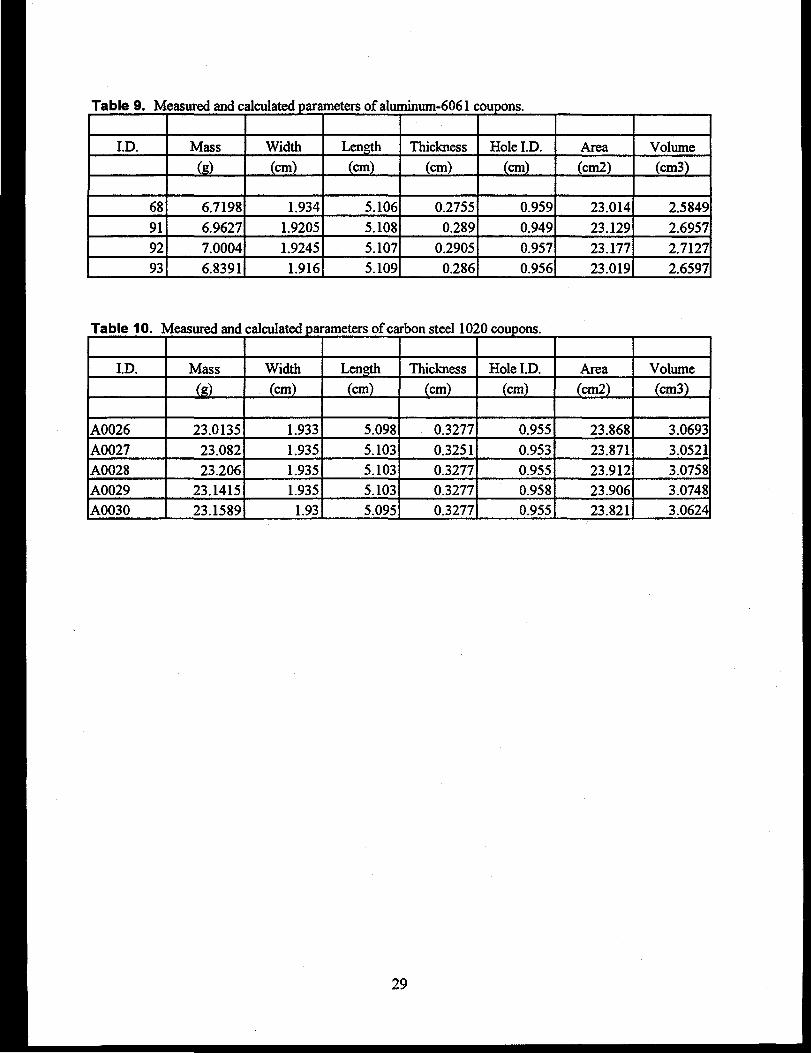
Table 9. Measured and calculated parameters of aluminum-6061 coupons.
ID.
68
91
9293
Mass
(g)
6.7198
6.9627
7.0004
6.8391
Width(cm)
1.934
1.9205
1.92451.916
Length
(cm)
5.106
5.108
5.1075.109
Thickness(cm)
0.2755
0.289
0.29050.286
Hole I.D.(cm)
0.959
0.949
0.9570.956
Area(cm2)
23.014
23.12923.177
23.019
Volume(cm3)
2.5849
2.6957
2.7127
2.6597
Table 10. Measured and calculated parameters of carbon steel 1020 coupons.
ID.
A0026
A0027A0028A0029A0030
Mass
(g)
23.0135
23.08223.206
23.141523.1589
Width(cm)
1.933
1.9351.9351.935
1.93
Length(cm)
5.098
5.1035.1035.1035.095
Thickness(cm)
0.3277
0.32510.32770.32770.3277
HoleLD.(cm)
0.955
0.9530.9550.9580.955
Area(cm2)
23.868
23.87123.91223.90623.821
Volume(cm3)
3.0693
3.05213.07583.07483.0624
29
8. TECHNICAL BASES FOR EXPERIMENT MIXTURE COMPOSITIONS
8.1 Experiment Mixture #1
Use: Bentonite 310 gKaolinite 270 gBoehmite 420 g
These relative amounts of clay and aluminum corrosion product were selected (Lords et al 1996) tosimulate ICPP-603 basin sludge for drying studies. The same materials and proportions are being usedfor the material interaction studies in order to be consistent with the drying studies. Variation of any ofthem by as much as a factor of 2 or 3 would probably make little if any difference in the amount ofcorrosion produced on stainless steel coupons.
The amount of water to add is arbitrary and probably does not matter for long-term tests. We addedwater in predetermined amounts to achieve a desired consistency (like a thin putty).
8.2 Experiment Mixture #2
Use the same basic mixture as above, but with added corrosion products and other materials tosimulate ICPP-603 basin silt (also called "sludge"). The compositions and amounts of additives usedwere based on chemical analyses of actual sludge. A copy of the analysis results of "603 sludge,"Analytical Chemistry log number 93-080214, is available.
Major Components
Fe is a "major" component, i.e. >5%, of the sludge. It is known to have originated from twosources: a) rust particles that fell into the basin from overhead structures and b) corrosion of welds,carbon steel, and stainless steel directly exposed to basin water. Based on knowledge that the mass of Feis small compared to the silicacious material in the sludge, it was recommended for Fe to comprise 5% ofthe test material. Because rust probably contributes most of the Fe, actual F^C^ is used to simulate 95%of the Fe and Fe(NO3)39H2O is used to simulate the remaining 5%. The small amount of Fe present in theclays can be ignored.
Si was also determined to be a "major" component comprising >5% of the sludge. Since airbornedust (particles of dirt or soil) is known to be by far the greatest contributor to formation of the sludge, theclays bentonite [5Al2O3"2MgO'24SiO2'5H2O(Na2O) and Al2.,7(A]0.g3Si3.i7)O,0(OH)2Naa33] and kaolinite(46%"SiO2,38% A12O3, and 2.1% TiO^ adequately simulate the Si.
Minor Components
Zn was reported as a "minor" component, i.e. between 0.1% and 5%. Its source of origin is fromdissolution of the Zn layer on galvanized steel in the basin. We selected Zn to comprise 0.5% of the testmaterial. Because such Zn has been dissolved and then at least partially precipitated to be in the sludge,
30
we used finely powdered ZnO to comprise 95% of the Zn, with Zn(NO3)2'6H2O providing the remaining5%.
Other minor components are Mg, Al, Ti and Ca. Mg, Al and Ti are all adequately simulated by theclays and the boehmite (which some references also call "clay.") The Ca, which originates from CaSO4
leached from the cement in the concrete pool walls, was recommended to comprise 0.2% of the testmaterial. It can be simulated with very finely powdered CaSO4.
Trace Components
Only "trace" amounts of B, Cu, Cr, and Pb were detected. Their presence at levels <0.1% is notexpected to significantly affect the test results, so we omitted them.
Chloride
Chloride is present at low levels, but it is not insignificant with respect to corrosion potential fromthe test mixture #2. Six basin sludge samples were analyzed for Cf with the following results: 573,508,890,607,512 and 544/^g/g, which averages 606 + 140/^g/g. For conservatism, the maximum level of 890Mg/g or 0.89 mg/g was used, rounded to 1.0 mg/g or 0.1 wt% of the "damp dried" sludge. The chloridewas added as NaCl. Almost any chloride compound could be used, but NaCl was selected because itshould not affect the pH, and the cation sodium should have little effect on the corrosion properties.
EHThe pH of the test material is very important with respect to corrosion. For at least the past decade,
the pH of ICPP-603 basin water has averaged 7.9. It was recommended for the pH of the watercontaining the dissolved/slurried additives listed above to be adjusted to pH 7.9 + 0.5 before it is mixedwith the clays. A portion of the final clay mixture could be slurried in high quality deionized water andthe pH checked at that time to verify that the pH of the test material is appropriate. The pH of eachmixture was determined to be within this range, so no adjustment was required.
31
9. MAKEUP PROCEDURES FOR EXPERIMENT MIXTURES
9.1 Experiment Mixture #1
Use: Bentonite 310 gKaolinite 270 gBoehmite 420 g
Dry: For a dry mixture, place the above materials in a bucket or container that is no more than50% full after the addition. Thoroughly mix by tumbling or stirring.
Wet: For a wet mixture, prepare as above. Then slowly add water with continuous electric-beater-type stirring until the desired consistency is attained. And then thoroughly stir itsome more to assure homogenous mixing. Be sure to measure and record the amount ofwater added. The water can be added all at once if a known, desired amount is measuredahead of time.
9.2 Experiment Mixture #2
Prepare a wet mixture as above, but first dissolve and/or slurry in water the materials listed below.These additional components are based on analyses of actual ICPP-603 basin sludge submitted underAnalytical Chemistry log number 93-080214. Major, minor, and trace amounts of various elements in thesludge were considered to be added to Mixture #2.
Majors (> 5%)
Fe Include Fe at 5% of the total weight of the dry mixture.
95% of the Fe is to be added as Y^O^. Use 67.9 g F&fi^ per kg ofdry mixture #1
5% of the Fe is to be added as Fe(NO3)3 9H2O. Use 18.1 g ofFe(NO3)3 9H2O per kg of dry mixture # 1.
Si Already adequately simulated by the clays.
Zn Include Zn at 0.5% of the total weight of the dry mixture.
95% of the Zn is to be added as finely powdered ZnO. Use 5.9 g of ZnO per kg of drymixture #1
5% of Zn is to be added as Zn(NO3)26HO. Use 1.14 g of Zn(NO3)26H2O per kg of dry mixture#1
32
Minors (0.1-5.0%)
Mg Already adequately simulated by the clays.
Al More than adequately simulated by the boehmite and the clays.
Ti Already adequately simulated by the clays.
Ca Include Ca at 0.2% of the total weight of the dry mixture. Simulate with finely powderedCaSO4. Use 0.59 g CaSO4 per kg of dry mixture #1.
Traces (<0.1%)
B Ignore. Not significant in the current tests.
Cu Ignore. Not significant in the current tests.
Cr Ignore. Not significant in the current tests.
Pb Ignore. Not significant in the current tests.
Chloride
Add 1.65 gNaCl per kg of dry mixture #1.
Preparation
Place all of the above additives into a beaker and add the total amount of water that is desired. Mixor stir long enough for the soluble components to dissolve. A small portion of the Fe,O3, CaSO4 and ZnOshould remain undissolved. Stir the solution just before it is added to the clay. Adjust the pH to 7.9+0.5with NaOH (and/or HNO3, if necessary). Add slurried solution to the mixed clays with adequate stirringand mixing as described above for the wet preparation of mixture # 1.
33
10. IRRADIATED FUEL STORAGE FACILITY
The radioactive (hot) material interaction experiments will be conducted in the Irradiated FuelStorage Facility (IFSF). The IFSF is a nuclear fuel storage facility located in the Fuel Receiving StorageFacility (ICPP-603) at the Idaho Chemical Processing Plant (ICPP), which is part of the Idaho NationalEngineering Laboratory (INEL). The IFSF, formerly known as Graphite Storage Facility (GSF), wasconstructed in 1974 at the ICPP to provide safe storage for spent, high-temperature, gas-cooled reactor(HTGR) fuels.
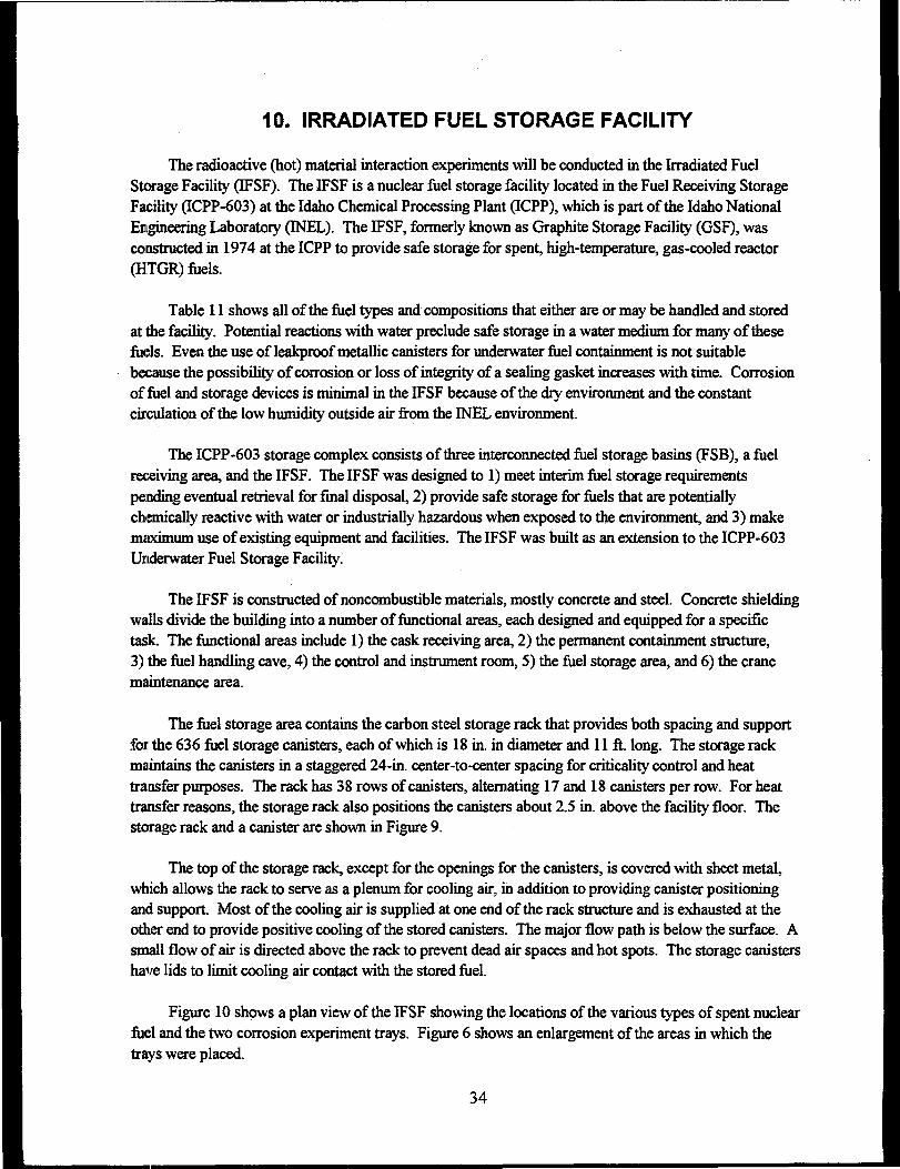
Table 11 shows all of the fuel types and compositions that either are or may be handled and storedat the facility. Potential reactions with water preclude safe storage in a water medium for many of thesefuels. Even the use of leakproof metallic canisters for underwater fuel containment is not suitablebecause the possibility of corrosion or loss of integrity of a sealing gasket increases with time. Corrosionof fuel and storage devices is minimal in the IFSF because of the dry environment and the constantcirculation of the low humidity outside air from the INEL environment.
The ICPP-603 storage complex consists of three interconnected fuel storage basins (FSB), a fuelreceiving area, and the IFSF. The IFSF was designed to 1) meet interim fuel storage requirementspending eventual retrieval for final disposal, 2) provide safe storage for fuels that are potentiallychemically reactive with water or industrially hazardous when exposed to the environment, and 3) makemaximum use of existing equipment and facilities. The IFSF was built as an extension to the ICPP-603Underwater Fuel Storage Facility.
The IFSF is constructed of noncombustible materials, mostly concrete and steel. Concrete shieldingwalls divide the building into a number of functional areas, each designed and equipped for a specifictask. The functional areas include 1) the cask receiving area, 2) the permanent containment structure,3) the fuel handling cave, 4) the control and instrument room, 5) the fuel storage area, and 6) the cranemaintenance area.
The fuel storage area contains the carbon steel storage rack that provides both spacing and supportfor the 636 fuel storage canisters, each of which is 18 in. in diameter and l i f t . long. The storage rackmaintains the canisters in a staggered 24-in. center-to-center spacing for criticality control and heattransfer purposes. The rack has 38 rows of canisters, alternating 17 and 18 canisters per row. For heattransfer reasons, the storage rack also positions the canisters about 2.5 in. above the facility floor. Thestorage rack and a canister are shown in Figure 9.
The top of the storage rack, except for the openings for the canisters, is covered with sheet metal,which allows the rack to serve as a plenum for cooling air, in addition to providing canister positioningand support. Most of the cooling air is supplied at one end of the rack structure and is exhausted at theother end to provide positive cooling of the stored canisters. The major flow path is below the surface. Asmall flow of air is directed above the rack to prevent dead air spaces and hot spots. The storage canistershave lids to limit cooling air contact with the stored fuel.
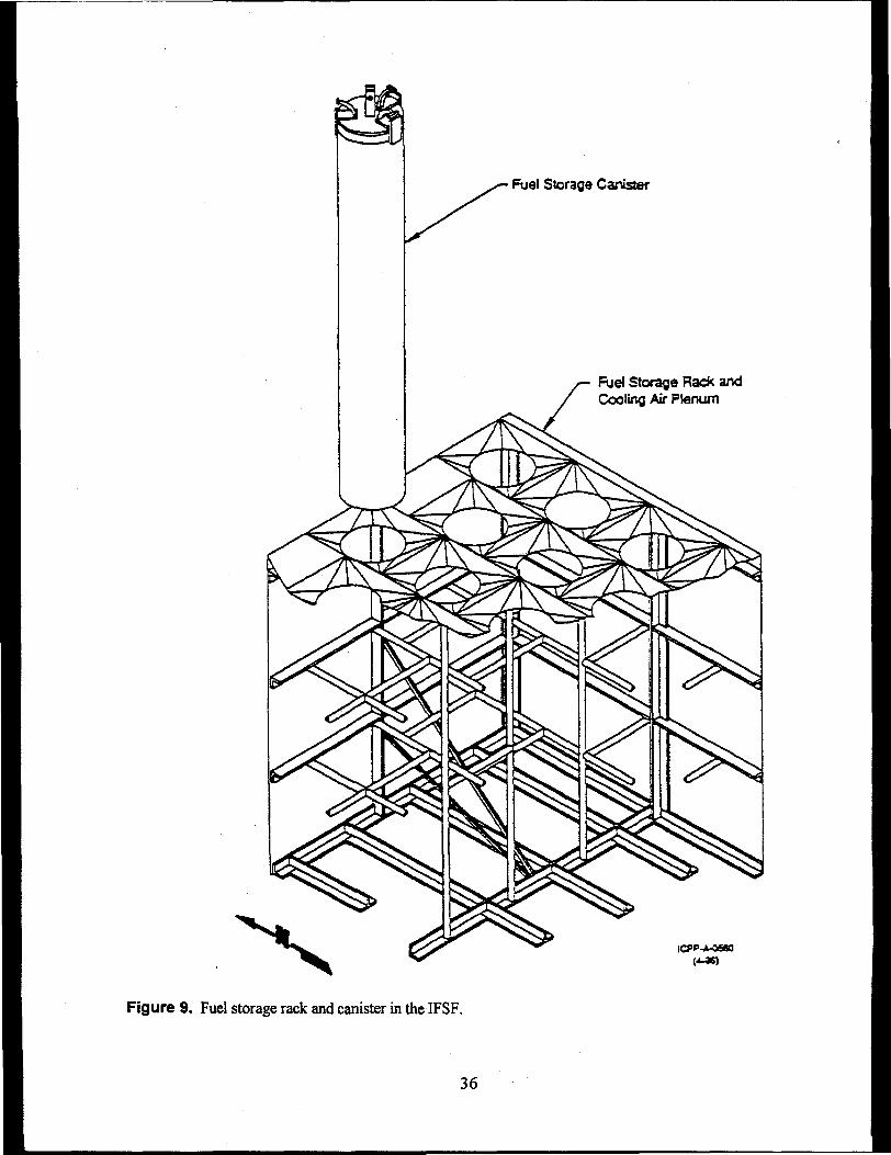
Figure 10 shows a plan view of the IFSF showing the locations of the various types of spent nuclearfuel and the two corrosion experiment trays. Figure 6 shows an enlargement of the areas in which thetrays were placed.
34
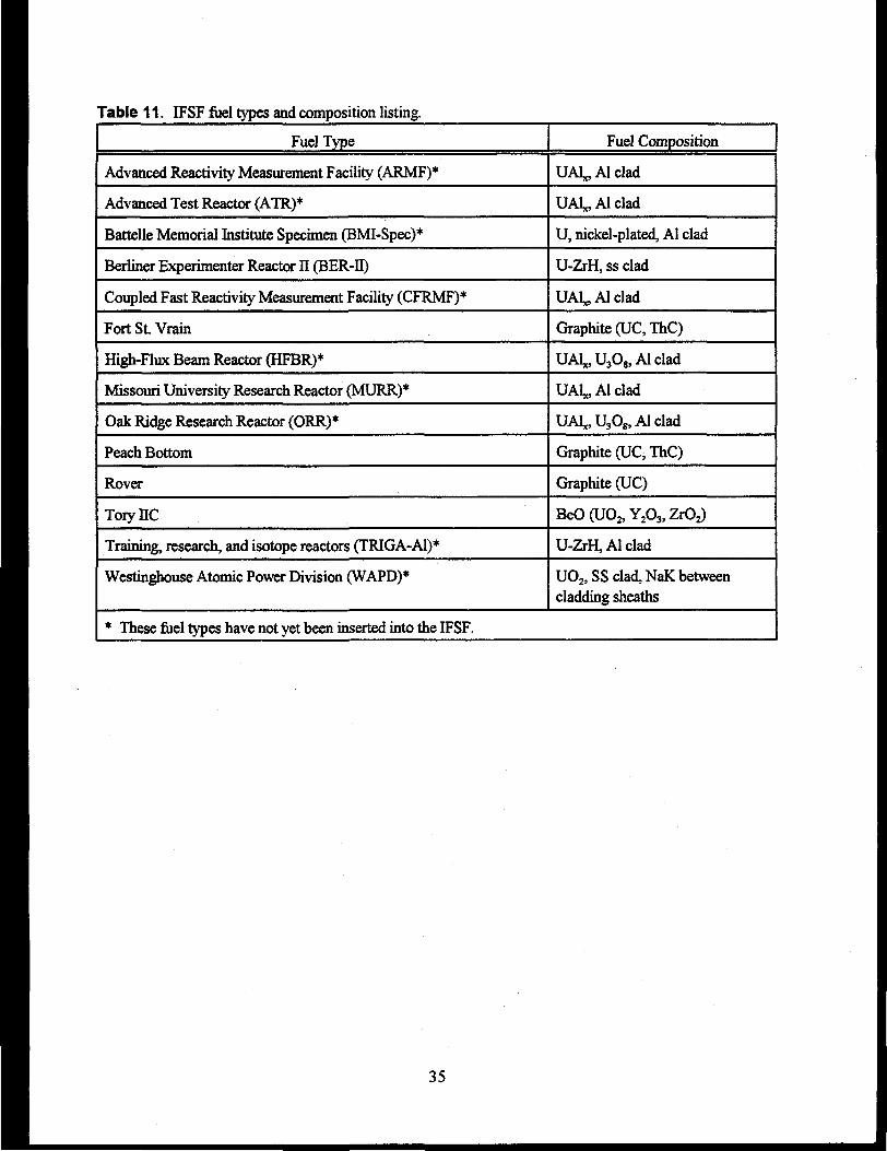
Table 11. IFSF fuel types and composition listing.
Fuel Type
Advanced Reactivity Measurement Facility (ARMF)*
Advanced Test Reactor (ATR)*
Battelle Memorial Institute Specimen (BMI-Spec)*
Berliner Experimenter Reactor II (BER-II)
Coupled Fast Reactivity Measurement Facility (CFRMF)*
Fort St. Vrain
High-Flux Beam Reactor (HFBR)*
Missouri University Research Reactor (MURR)*
Oak Ridge Research Reactor (ORR)*
Peach Bottom
Rover
ToryllC
Training, research, and isotope reactors (TRIGA-Al)*
Westinghouse Atomic Power Division (WAPD)*
Fuel Composition
UAl^Alclad
UA^Alclad
U, nickel-plated, Al clad
U-ZrH, ss clad
UA^Alclad
Graphite (UC, ThC)
UAkUsO^Alclad
UAl^Alclad
UA^UsO^Alclad
Graphite (UC, ThC)
Graphite (UC)
BeO(UO2,Y2O35ZrO2)
U-ZrH, Al clad
UO2, SS clad, NaK betweencladding sheaths
* These fuel types have not yet been inserted into the IFSF.
35
Fuel Storage Canister
Fuel Storage Rack andCooling Air Plenum
Figure 9. Fuel storage rack and canister in the IFSF.
36
QuoyQQQOQOOOQS
QQQOQQGDQl®0000000QGQGGQQDOOODUOi
oooooooc ¥ ¥ ¥,¥Ax xoj aOOOOO oooo
oooo oooo2QUQQ®QQQQooooooooo
OOQOQQQOQOOQOQIQIQIOIQ
QlQlOIQlQQlQigigiOlQlOlQQlQlQrQlQ
lOlOlOIOlOlOIOiOIOIOIOIOI'
QOOOOOOOOOClOOOQOO
i
onnooooooooooQQioo
QQQOQOQQOQ
QDDOQQOODQQQQQQOOO00000000000000000
G
Figure 10. Plan view of the IFSF showing the locations of the various types of spent nuclear fuel andthe two corrosion experiment trays.
37
11. REQUIREMENTS FOR CORROSION TRAY
1. Must be able to hold 9 wide mouth jars filled with clay mixtures
2. Must be able to rest between the IFSF canister lids (some tilting is allowed)
3. Must be able to use shuttle bin operations without falling down the hole in the middle
4. Must be able to be moved with a crane
5. Must be designed to reduce probability of being tipped over or dropped accidentally by the crane
6. Must have a rod to prevent jars from falling out if tray is tipped over
7. Must contain holes to allow venting with the air in IFSF and to allow water to drain out
8. Must be able to hold radiochromic film that can be replaced easily
9. Must be able to hold a thermometer
10 Must keep jars from banging into each other
11. Must be designed to reduce probability of bumping into handles on the canister lids
12. Must load tray such that it remains relatively balanced while hanging from the crane
13. Must be able to screw 3 carbon steel coupons on the top of the tray
14. Must not contain jars with mixtures that run easily when jars are tipped over.
38
1.
2.
12. DESIRED POST-EXPERIMENT COUPON MEASUREMENTS
Results from the experiments will include the following:
Record appearance of coupons (corrosion products/pits/cracks) and take photographs
Determine the rate of mass loss by weighing each coupon before and after each experiment. Thecorrosion products will be removed from the coupons before they are weighed
3. Perform a surface analysis when needed (depth of pits and cracks)
4. Determine coupon degradation mechanisms
5. Record the coupon radiation doses and the maximum/minimum tray temperatures.
No results are reported here because the steel coupons must remain in the sludge mixtures for atleast a few months before being removed and examined. Some of the coupons will remain in themixtures for several years before examination.
After the specimens are removed from the test solutions they will be cleaned according to approvedmethods (see item 1 of Section 4.0). The coupon will be scrubbed, rinsed, and dried in a manner similarto the preparation procedures. Then the coupon will be measured carefully and weighed to the nearest0.0001 g. Calculations will be made that reflect the percent weight change and corrosion rate. Asspecified in the ASTM standards, the corrosion rate (CR) will be calculated by the following equation:
CR = (mass lost)(surface area)(time of exposure)(density)
After preparation, measurement, gravimetric observations, and calculations, the coupon will bevisually inspected with magnification. Photomicrographs, electron micrographs, and other highmagnification evaluations may be performed to fully document the corrosive action encountered.
These experiments are designed to resolve possible concerns about the safety and longevity of drystorage of SNF. The results could also lead to safer and more economical methods of transfer and storageofSNF.
39
13. REFERENCES
Ailor, W.H., 1982 Atmospheric Corrosion. John Wiley and Sons Publishing.
Andersen, P.L., H.D. Solomon, and D.F. Taylor. 1981. Basic Studies on the Variabilities of FabricationRelated Sensitization Phenomena in Stainless Steels. EPRINP-1823, Electric Power ResearchInstitute, Palo Alto, California.
ASTM. 1993. Standard Practices for Detecting Susceptibility to Intergranular Attack in AustenticStainless Steels. ASTM A262-1993, American Society for Testing and Materials, Philadelphia,Pennsylvania.
Berry, W.E. 1971. Corrosion in Nuclear Applications, pp. 253. John Wiley and Sons, Inc., New York.
Bruemmer, S.M., R.N. Jones, J.R. Divine, and A.B. Johnson, Jr. 1984. "Evaluating the Intergranular SCCResistance of Sensitized Type 304 Stainless Steel in Low-Temperature Water Environments."ASTM Special Technical Testing Publication 821, American Society for Testing and Materials,Philadelphia, Pennsylvania. PNL-SA-10053, Pacific Northwest Laboratory, Richland Washington.
Dirk, W.J. 1994. "Corrosion in ICPP Fuels Storage Basins." Corrosion 94, National Association ofCorrosion Engineers, Houston, Texas.
Gilbert, E.R., W.J. Bailey, A.B. Johnson, Jr., and M.A. McKinnon. 1990. "Advances in Technology forStoring Light Water Reactor Spent Fuel." Nuclear Technology, 82:141-161
Guenther, Johnson, et al. 1994. Initial Evaluation of Dry Storage Issues for Spent Nuclear Fuels in WetStorage at the Idaho Chemical Processing Plant, Pacific Northwest Laboratory,Richland, Washington.
Hoskins A.P., J.G. Scott, C.V. Shelton-Davis, and G.E. McDannel. 1993. Fuel Performance in WaterStorage. Idaho National Engineering Laboratory, Idaho Falls, Idaho.
International Atomic Energy Agency (IAEA). 1982. Storage of Water Reactor Spent Fuel in WaterPools: A Survey of World Experience. Technical Report Series 218, Vienna, Austria.
International Atomic Energy Agency (IAEA). 1988. Survey of Experience with Dry Storage of SpentNuclear Fuel and Update of Wet Storage Experience. Technical Report Series 290, Vienna,Austria.
Jones, R.H. 1992. "Assessment of H-Induced Crack Growth of Type 315 SS at ITER Conditions."Fusion Reactor Materials Semiannual Progress Report for the Period Ending March 31,1992.DOE/ER-0313/12, Oak Ridge National Laboratory, Oak Ridge, Tennessee.
Johnson, Jr. A.B., A.L. Lund, and S.R. Pednekar. 1994. Estimates of Durability ofJM-2 Core DebrisCanisters and Cask Liners. PNL-9457, Pacific Northwest Laboratory, Richland, Washington.
40
Johnson, Jr. A.B., A.L. Lund, and S.G. Pitman. 1995. Estimates of Durability o/IM-2 Core DebrisCanisters In Elevated-Chloride Environments. Pacific Northwest Laboratory, Richland,Washington.
Lords, R.E., W.E. Windes, J.C. Crepeau and R.W. Sidwell, 1996. Drying Studies of Simulated DOEAluminum Plate Fuels. DOE Spent Nuclear Fuel and Fissile Material Management, p. 329-336.American Nuclear Society, La Grange Park, Illinois.
Lundberg, L.B., 1994. Corrosion of Spent ATR Fuel Elements Relative to Their Dry Storage. ERA-NRE-94-096, Idaho National Engineering Laboratory, Idaho Falls, Idaho.
Mattson, E. 1982, "The Atmospheric Corrosion Properties of Some Common Structural Metals - AComparative Study." Materials Performance 21(7)9-19.
NACE 1984, L.S. Van Delinder, ed. Corrosion Basics: An Introduction. National Association ofCorrosion Engineers, New York.
Schleicher, H.W. 1963. "Corrosion Studies in Organic Coolants for Nuclear Reactors." Proceedings ofthe Second International Congress on Metallic Corrosion, pp 432-441. National Association ofCorrosion Engineers, New York.
Szklarska-Smialowska, Z. 1986. Pitting Corrosion of Metals, p. 202. NACE.
U.S. Department of Energy (DOE). 1993b. Volume II, Spent Fuel Working Group Report on Inventoryand Storage of the Department's Spent Nuclear Fuel and Other Reactor Irradiated NuclearMaterials and Their Environmental Safety and Health Vulnerabilities. U.S. Department of Energy,Washington, D.C.
U.S. Department of Energy (DOE). 1992. Operating Experience Feedback Report-Analysis of CorrosionRelated Occurrences. DOE/DP-0116, U.S. Department of Energy, Washington, D.C.
Wheeler, D.J. 1984. "Choosing the Right Storage Medium." Nuclear Engineering International.centuries.
41
Appendix A
Corrosion Overview
Appendix A
CORROSION OVERVIEW
General uniform corrosion is affected by the chemical composition of the corrosive medium, watercontent, temperature, and alloy composition. Water that is in contact with the surface of the metal servesas the electrochemical path for corrosion reactions. Differing electrical potentials may arise on thesurface of many metal structures for varying reasons, including different chemical environments. Whenthis happens, one area of the structure becomes the cathode (reduction), while one area becomes theanode (oxidation). The anodic area loses electrons, and the metal transforms into metallic ions that moveinto solution in the water. This loss of metal atoms weakens the structure by producing pits, cracks, orgeneral failure at the area of corrosion. The electrons move along the structure to the cathodic area andreduction takes place.
This weakening of the structural properties of metal may present a problem in the area of SNFstorage. The stainless steel containers that will hold spent fuel in a dry environment are very resistant tocorrosion under normal conditions. However, external factors such as sensitization, stress, elevatedtemperatures, gamma radiation, presence of microbes, and exposure to elevated concentrations ofchemicals may speed the corrosion reaction along the affected surface areas of the storage structures.
Acceptable movement of spent nuclear fuel from wet storage to dry storage must take into accountthe potential for corrosion of the stainless steel containment vessels. In order to recommend dry storageconditions for the spent nuclear fuel now stored in the ICPP wet storage basins, information on the paststorage history, fuel condition, and failure mechanisms for the spent nuclear fuel must be identified. Thismust be accomplished in order to determine potential impacts on dry storage or other operations that maybe conducted prior to dry storage. Valuable information will be obtained from experiments beingperformed to identify the corrosion mechanisms of the stainless steel canisters in a "cold" environment(absence of all but background radiation) worst case scenario along with the effects of the "hot"environment (gamma radiation field present). A preliminary research trail has been established, whichwill assist in determining the most probable corrosion mechanism in the areas adjacent to the weld areasof the canisters. Also, background information concerning the types of materials to be evaluated and thephysical environments that may affect the corrosion of the canisters is reported.
The SNF exposed to the ICPP-603 water has been subjected to relatively aggressive conditions.These include extended time underwater, addition of chloride to the water basin, and the formation ofsludge from blowing sediment through the bay doors. The experiments concentrate on the corrosionenhancement effects of the sludge and the chemicals present in the sludge on the SS canisters. Airbornesediment was deposited in the basin as the doors were opened and closed while admitting fuel to the area.With the butt welds exposed to a sludge similar to the sludge formed on the SNF and its cladding in thewet storage facilities, the ionic composition of the sludge may have an adverse corrosion effect on thesensitized areas of the SS canisters. Even though the SNF has been through a drying process (afterremoval from the wet storage basins), there will remain anywhere from five to two-hundred fifty poundsof water associated with many of these spent fuel elements after they are sealed in dry storage canisters.It is possible that some of the sludge will fall into the bottom of the SS canister, as shown in Figure 1.
A-l
While the number of corrosion-related occurrences for all of the Department of Energy's (DOE)Defense Programs facilities totals only 1.5% of the reported occurrences (DOE 1992), such degradation,if uncorrected, can lead to undesirable results. The need for the evaluation of the degradationmechanisms of the materials in the Irradiated Fuel Storage Facility is supported by the known corrosionof storage components in ICPP-603 (Dirk 1994).
The standard, used to compare stainless steel with other metals, is based on the general atmosphericcorrosion rate for stainless steels, as evaluated by the International Nickel Company (Ailor 19S2) in amarine air environment. Specimens of 304 stainless steel had an average corrosion rate of 0.03 um/yafter 15 years. Long term (26 year) atmospheric studies on stainless steel 304L (SS-304L) yieldedcorrosion rates of less than 10 um/y. The concentration of chlorides obtained from the corrosionproducts were found to be 1225 ppm Cl" (Johnson et al. 1995).
One particular study showed that type 304 stainless steel (SS-304) has had no observable corrosionafter 13 years, but galvanic corrosion has been observed on carbon steel (CS) welded to SS-304. Also,algae observed on nonradioactive specimens durings recent examinations of the ICPP-666 facilitysuggests the possibility of microbially influenced corrosion (MIC) on some of the structures (Hoskins etal. 1993).
These experiments help us investigate corrosion that may exist where airborne substances, blown infrom the desert at times when bay doors were opened, have settled on the SNF assemblies to be stored inSS containers. It is possible that this sludge contains chemical and/or biological contaminants that mayenhance corrosion activity at such sensitized points around the weld.
Numerous fuel types now stored in the ICPP-603 and ICPP-666 facilities do not have prior drystorage precedents and need to be evaluated to determine whether the transition from wet to dry storagehas; special issues not previously addressed with fuel types for which there is experience. Some fuelcladdings in ICPP-603 are known to be breached, exposing the metallic fuels to aqueous corrosion thatcould include generation of uranium oxides and hydrides. Another consequence of cladding failureincludes the release of fission gas if pinholes are formed.
The older of the two facilities, having stored spent nuclear fuel since 1959, is ICPP-603. One of theintentions of this experiment is to approximate the physical and chemical environment of the storagefacility. This is accomplished by using a water based sludge containing ions found in these pools. Intothis sludge, a stainless steel welded coupon is placed to attempt to replicate corrosion expected in drystorage of SNF.
ICPP-603 consists of three unlined concrete pools filled with water and holds 41 different types ofspent nuclear fuel received as early as 1959. The fuel types stored in this pool include metals, alloys,hydrides, and oxides in several different fuel matrices. The majority of the spent nuclear fuel is clad withAl, stainless steel, or Zircaloy, but some spent nuclear fuel is either unclad or has defective cladding. Asludge has also formed in these basins, and contains a mixture of the corrosion products of these SNFelements, cladding, and airborne materials from the surrounding desert environment. This sludge wasanalyzed and modeled by scientists at the ICPP for the purpose of creating a chemically compatibleenvironment for the experimental SS coupons. Our experiments using welded stainless steel coupons
A-2
submerged in this sludge are underway in an attempt to discover whether or not there is general corrosionor a localized attack at or around the weld area.
Important facts in the design and sequence of events in the storage environment for ICPP-603include a long service time (>40 yr.) and the development of an aggressive pool chemistry, due toalgicides, including up to 800 ppm chloride during one period of time. A summary of the algicides alsoincludes calcium hypochlorite, chlorine, and iodine. However, chloride levels were down to about50 ppm by 1994.
The chloride levels are of significant importance because of the aggressiveness of chloride ions(Cl~) on many materials including stainless steels. Chloride levels have changed because of the need toeliminate algae and because the water system was changed from a once-through system to a recirculatingsystem that required cleaning the water. To control water conditions, nitrates, new water, and UV lightswere used. A summary of the historical pool chemistry for ICPP-603 includes a pH of 5.0 - 8.5, aCl~ content of up to 800 ppm, a temperature of 20 °C, and a conductivity of 600 uS/cm. Conversely, thehistorical pool chemistry for ICPP-666 shows that the pH, was controlled at 5.5, a chloride level of30 ppb, a temperature of 20 °C, and a conductivity of 1 uS /cm.
The cladding, buckets, and storage cans used for wet fuel storage are fabricated from one of threedifferent materials: stainless steel, carbon steel, or aluminum. There are few data on the integrity of theindividual cans, except for some underwater visual inspections and Fermi mock-up can testing. Thestatus of some of the materials, based on these sketchy data, include severe corrosion of Al-alioy andcarbon steel fuel buckets and storage cans. The stainless steel buckets and cans seem to be relatively freeof general corrosion. The metallurgy of stainless steel and its resistance to corrosion is an important itemto consider before moving this material to dry storage.
An overall view of metallurgy focuses on two basic solid substances. These are substituted solidsolutions and interstitial solid solutions. For example, carbon steel is a mixture of an interstitial solidsolution of carbon in body centered cubic iron and an intermediate metallic compound Fe3C calledcementite. In many cases, multiphase materials present a problem from a corrosion standpoint becausethe two phases may have marked differences in electrochemical characteristics. This usually happens inalloys.
Austenitic stainless steels (SS) are composed of basically four elements in differing proportions.Iron, carbon, chromium, and nickel are alloyed to produce these stainless steels. The 300 series(containing nickel in significant amounts) stainless steels are more corrosion resistant than the 400 seriesstainless steels (which contains Fe, C, and Cr with no nickel) series, with notable exceptions in thepresence of chloride ion. The materials tested in these experiments are the 304L (70.3% Fe, 0.02% C,18.2% Cr, and 8.25% Ni) and the 316L (68.7% Fe, 0.02% C, 16.3% Cr, 10.1% Ni, and 2.1% Mo).
Austenitic stainless steel is essentially nonmagnetic and cannot be hardened by heat treatment.These alloys must be cold-worked only, which leads to stresses and some possible sensitization whenbending. Most contain nickel as the principal austenite former and possess better corrosion resistancethan straight chromium steels. The workhorses of these alloys are labeled as 304,304L (the L meanscarbon content of less than 0.03 %), and 316. The molybdenum bearing 316 is considerably better in
A-3
many applications than 304. Stainless steel 316 exhibits much better resistance to pitting, sulfuric acid,and hot organic acids. However, SS-304 has better corrosion resistance than SS-316 in nitric acid.
A heat effect called sensitization occurs whenever the 300 series stainless steels are heated between427 °C and 760 °C. This forms chromium carbides at the grain boundaries, thus tying the Cr with C andnot allowing Cr to act as a deterrent to corrosion. These grain boundaries are now subject tointergranular attack and are anodic to the surrounding grains. The coupons used in our experimentswere welded at a temperature approaching the melting point of stainless steel (1300 °C) and were notstress relieved, thus adding to the worst case scenario for this experiment, hi the heat-affected zonesadjacent to the weld, sensitization may have occurred. However, the L grades of stainless steels havevery little or no tendency toward sensitization because of the very low carbon levels (NACE 1984). Alsoduring welding, a large variation of thermal expansion occurs between the solidifying molten metal pooland the base metal. Upon solidification, this often results in high residual tensile stresses, which may leadto rapid deterioration and destruction in this area in a hostile environment (NACE 1984). Under thesecircumstances, stress corrosion cracking may occur in a hostile chemical environment. The SS-304 andSS-316 grades of stainless steel are highly susceptible to stress corrosion cracking, particularly bychloride ions.
Stainless steels are resistant to general corrosion over the entire surface area of the structure, butvery few structures are immune from localized corrosion. Localized corrosion is a selective attack on ametal by corrosion in small special areas or zones. One of the more important types of localizedcorrosion is pitting. Pitting is a type of localized corrosion where small volumes of metal are removed toproduce craters or pits. Another localized corrosion type, intergranular corrosion, takes place whensmall volumes of metal are preferentially removed along paths that follow grain boundaries, producingfissures or cracks. Environmental cracking takes place when there are extraneous stresses that mayproduce localized corrosion cells because of the environment in which the structure is located. There arethree major types of environmental cracking. Stress corrosion cracking is a spontaneous brittle fractureof a susceptible material under tensile stress after the material has been in a specific environment for aperiod of time. This is an anodic process. Hydrogen induced cracking is a cathodic process wherenascent hydrogen competes for the lattice bonding electrons or the formations of metallic hydrides in thepresence of chemical poisons such as H2S. In normal cases, hydrogen gas is formed at the cathode, andthe gas escapes rather harmlessly in a vented container. Finally, Liquid metal cracking (aphysicochemical process) occurs when molten metals come in contact with a surface over a period oftime. This process will not be considered as an avenue for corrosion in our experiments.
Selection of canister material must be based on both interior and exterior environments. There areseveral considerations for the exterior environment.
1. Will the canisters be stored in a dry facility or submerged in a storage pool?
2. What is the expected duration of interim storage?
3. What are expected temperatures and environments?
Stainless steel, because of its resistance to general corrosion, is chosen for storage structures inmany spent nuclear fuel facilities. For example, the durability of stainless steel canisters holding debris
A-4
from the TMI-2 core was estimated for both wet and dry conditions (Johnson, Lund, and Pednekar 94). Itwas predicted that at 20 °C (68 °F) in moist air or in water (2 ppm Cl"), durabilities will exceed anyforeseeable interim storage period.
Stainless steels are highly resistant to general corrosion with the formation of a protective oxide andcan exhibit excellent integrity in environments that do not promote localized corrosion. Stainless steel(tie-plate) coupon data from the ICPP-603 indicate a negligible loss of material over 15 yrs. Thecorrosion rate for the coupons was less that 3.3 um/yr with a confidence level of about 95 %. The lowgeneral corrosion rates cited in the INEL coupon studies are basically concerned with cladding materialsand not canisters exposed to sludge.
In one general corrosion study (NACE 1984) the oxide layer correlated to 60% of the total corrosionpenetration. If the process is not taken to be diffusion-limited, the oxide layer penetration corresponds toa corrosion penetration of 1.6 to 2.4 um while in a reactor. The type 304 oxide layer measurementcorrelated well with oxide layer thickness measurements of 6 um from a SS-304L light water reactor(LWR) assembly that had been irradiated for three cycles in the Haddam Neck reactor (NACE 1984).This oxide layer appeared tenacious and stable after a five-year period of storage in a PWR spent fuelpool. Therefore, the stainless steel canisters considered for this study are not expected to fail in waterstorage or dry storage by general corrosion due to the protective nature of the oxide film.
The introduction of chloride ions for algae control changed the corrosion expectations of stainlesssteel (Schleicher 1963). It was discovered that coupon weight changes were 30 times higher for increasesin the chloride level from 3 ppm to 200 ppm at 450 °C. Corrosion rates are similar for tests with bothirradiated and unirradiated coupons. Corrosion particles, consisting primarily of FejG,, Fe2C, and F^O^were found in the Organic Moderated Reactor Experiment (OMRE) coolant from corrosion of the steelreactor vessel.
Most of the studies on corrosion have been completed in moist air environments, waterenvironments, and soil environments. This study will investigate the effect of a sludge that is in contactwith a sensitized area of a stainless steel structure. A number of factors from other studies will beinvestigated, including environmental conditions, sensitization of the metals, internal and externalstresses, plus other factors that enhance the probability that corrosion will occur on metallic surfaces.Some of the mechanisms of corrosion that may affect the surface integrity of stainless steel structures incontact with the sludge are described below.
Intergranular Stress Corrosion Cracking (IGSCQ: If stresses are present in this aggressiveenvironment above some threshold value, IGSCC may occur. Stress corrosion cracking requires theconfluence of a susceptible microstructure (i.e., sensitized), a tensile stress (residual stresses from weldingoperations), and an aggressive environment. Bruemmer (1984) identified conditions necessary forIGSCC in sensitized Type 304 stainless steel in water at 32°C. The conditions were a combination of 1)chlorides > .5ppm, 2) bulk carbon content > .06 wt%, and 3) applied stress > 1.4 times the yield strength.Higher temperatures such as fuel storage temperatures, increase the aggressiveness of the environmentand promote the initiation of IGSCC. Sensitization can occur during irradiation at temperatures as low as427°C and at temperatures as low as 482 °C in the absence of neutron radiation. Water environments andmoist air environments have produced rapid corrosion and cracking in sensitized stainless steel, even atspent fuel pool temperatures. For example, tests relating to Three Mile Island (TMI) canisters were done
A-5
on U-bend SS-304L specimens in contact with Cl" levels of 25-470 ppm, pH values of 7.3 to 8.1, incontact with tuff rock, and saturated air for a period of 25 months. These tests showed that sensitizedspecimens failed by intergranular stress corrosion cracking (Johnson et al. 1995). Specific to the fuels inICPP-603, IGSCC was identified as a potential failure mechanism.
Galvanic Corrosion: Galvanic corrosion arises from the galvanic coupling of stainless steel cladfuel with Al or carbon steel (CS) cans used for storage. The stainless steel will be noble to the Al and CS,so corrosion of the cans will accelerate preferentially to the corrosion of the CS. Large cathode-to-anoderatios will serve to further accelerate the corrosion of the less noble material.
Crevice Corrosion: Crevice corrosion may be exhibited for tight crevices. Crevice corrosion foraustenitic stainless steel is accentuated by the presence of aggressive anions such as Cl'. At high Cl"concentrations, the fuel that has been in water storage would be vulnerable to varying amounts of crevicecorrosion dependent on the tightness of the crevice.
Hydrogen embrittlement: Most literature indicates that hydrogen embrittlement in stainless steelis not a prevalent degradation mechanism. Hydrogen is thought to have a low solubility and highmobility in austenitic stainless steel, which reduces the trapped hydrogen in the material. This makes theaustenitic stainless steel resistant to hydrogen cracking. However, Jones (92) has observed hydrogen-induced crack growth in irradiated 316 stainless steel at 100 °C. Therefore, the issue of hydrogen-inducedcrack growth has not been clearly resolved in the literature.
Intergranular Attack (IGA): IGA is the sensitization of stainless steels characterized by theformation of chromium carbides at the grain boundaries that deplete the chromium in the areas directlyadjacent to the grain boundaries and render the material susceptible to environmentally induced corrosion.In order for sensitization to be an issue, the material must be held for a minimum amount of time at atemperature above the threshold temperature for diffusion to occur to deplete the chromium levelsadjacent to the grain boundaries. These zones of chromium depletion can become prone to corrosionwhen exposed to a sufficiently aggressive environment, resulting in IGA.
Irradiation Assisted Stress Corfosion Cracking (IASCC): Chromium depletion can also occurwithout carbides being formed as the result of radiation induced segregation, which leads to IASCC. Thisalso may be of some importance in the radioactive experiments.
Microbially Influenced Corrosion (MIC): Corrosion by water and steam are concerns worldwide.Stainless steel grades containing Mo (316L) may be used in sea water because of their resistance to the
chloride ion induced corrosion. Their performance, however, may be contingent upon high velocity (>4m/s), aeration, and freedom from deposits of scale or marine organisms. The regular carbon grades (SS-304 and SS-316) may be subject to intergranular corrosion in natural waters under some conditions(NACE 1984). These conditions would include high chloridity, bacterial action, and oxygen cells.
Troublesome microorganisms are apt to cause corrosion. Slimes, which include fungi, yeasts,bacteria, and entrapped quantities of inorganic and organic materials, often attack sensitized areas ofmetals and begin the process of corrosion. Slime deposits can cause oxygen cell type corrosion andpitting. Bacteria such as Sporovibrio desulfuriccm (sulfate reducing bacteria), which generates H2S bymetabolizing sulfates, and Crenothrix, ("iron-eating" bacteria), which metabolizes soluble iron and
A-6
mangananese while excreting the oxides, may also be present in the water or airborne particulates foundat the ICCP facility. These microorganisms are controlled by chlorination procedures, which inthemselves are causes of corrosion.
Bacteria in the sludge could also increase the O2 concentration at the canister area, thus producingan oxygen concentration cell.
Oxygen concentration cells: Corrosion in soils or sludges is sometimes attributed to oxygenconcentration cells (differential oxygen cells - differential aeration cells) which, as a result of someaction, produce an oxygen gradient along the surface of a structure. The area that contains the highestconcentration of oxygen is the cathode, while that part with little oxygen supply is the anode and willcorrode.
Corrosion due to temperature changes, called temperature cells, is the result of two electrodesformed on the same metallic surface. The electrode at the higher temperature becomes the anode and thuswill corrode. The electrode at the lower temperature becomes the cathode.
Corrosion due to surface film cells is a real possibility because a film, only a few atoms thick, mayform on metals with a potential as much as 0.3 volts different from the unfilled metals. This galvaniccouple may produce corrosion. However, it is more usual to speak of how the oxide films preventcorrosion. Stainless steels are known for their ability to form such films, and thus owe much of theircorrosion resistance to them. Aluminum oxide film represents a resistance barrier rather than a change inpotential. Aluminum, in practice, is a much more corrosion resistant metal than would be expected fromits potential in the Electrochemical Series because of this highly resistive film.
Combination cells may also be at work weakening the structures. These cells are produced bymore than one type of corrosion mentioned here. Sometimes they work together to produce morecorrosion. For example, an oxygen cell and a temperature cell can be acting together to produce evenmore corrosion than either could produce alone.
Stainless steel has a proven track record for resisting general corrosion. However, the possibility oflocalized corrosion exists in the present spent nuclear fuel storage facilities at the ICPP. Stainless steelthat could come into contact with wet sludge, may be more vulnerable to localized corrosion than generalcorrosion. This sludge is a mixture of fuel and cladding corrosion products, clays, ions, bacteria, andother materials from air-borne particulates that settled in the fuel storage pools at ICPP. During the drystorage of the SNF, some of the sludge attached to the spent fuel rods and cladding may becomedislodged. If this sludge material is moist and comes into contact with the weld areas of the stainless steelcanisters, corrosion is possible. This corrosion may be enhanced by the chemical composition of thesludge, elevated temperatures, and/or by the presence of the gamma field in the dry storage environment.
We do not expect much corrosion of the stainless steel coupons used in our experiments. If that isthe case, our experiments will demonstrate to the NRC, others, and ourselves that canisters made withSS-304L or SS-316L will be reliable for the dry storage of spent nuclear fuel over decades and evencenturies.
A-7