Embed Size (px)
Citation preview
Corrosion Science 79 (2014) 198–205
Contents lists available at ScienceDirect
Corrosion Science
journal homepage: www.elsevier .com/locate /corsc i
Corrosion mechanism of an Al–BN abradable seal coating systemin chloride solution
0010-938X/$ - see front matter Crown Copyright � 2013 Published by Elsevier Ltd. All rights reserved.http://dx.doi.org/10.1016/j.corsci.2013.11.007
⇑ Corresponding author. Tel.: +86 24 2392 5323; fax: +86 24 2389 3624.E-mail address: [email protected] (Y. Li).
Bing Lei a, Man Li a, Zhongxing Zhao b, Lu Wang b, Ying Li a,⇑, Fuhui Wang a
a State Key Laboratory for Corrosion and Protection, Institute of Metal Research, Chinese Academy of Sciences, 62 Wencui Road, Shenyang 110016, Chinab Liming Aero-Engine Group Corporation, Shenyang 110016, China
a r t i c l e i n f o a b s t r a c t
Article history:Received 2 July 2013Accepted 11 November 2013Available online 18 November 2013
Keywords:A. AluminumA. Metal coatingsB. PolarizationC. Pitting corrosionC. Negative difference effect
The corrosion mechanism of an Aluminum–Boron Nitride (Al–BN) abradable coating system (with NiAlbond layer and 0Cr17Ni4Cu4Nb substrate) in chloride solution has been investigated by potentiodynamicpolarization and volumetric tests. Galvanic interaction of the coating system during corrosion has beenconfirmed. Upon coupling, the Al–BN layer assumes anodic character, while the bond NiAl and substrateact as cathodes. Spontaneous pitting is aroused on the Al matrix of the Al–BN layer due to the galvanicinteraction. The Negative difference effect (NDE) of the Al–BN has been discussed.
Crown Copyright � 2013 Published by Elsevier Ltd. All rights reserved.
1. Introduction
Abradable seal materials are widely employed in aero-engine tominimize the clearance between rotating and stationary parts andthereby enhance aero-engine efficiency [1–3]. Typical locations forabradable materials application in aero-engine include the fan, lowpressure compressor, and high pressure compressor sections [4].During operation, the rotating blade wear-in the abradable mate-rial, producing a rub track where the blade tips rotate while seatedwithin a groove in the abradable coating, which ensures more gasis drawn through the blade area and less escapes over the bladetips [5,6]. Abradable seal materials often operate in highlydemanding environments and the required physicochemical prop-erties such as abradability, erosion resistance, high-temperaturestabilization, and sufficient bond strength to the underlying mate-rial are often achieved by using multiphase materials consisting ofa metal matrix, a self-lubricating non-metallic phase and a definedlevel of porosity [7–9]. Furthermore, a dense bond layer, typicallyNiAl intermetallic is provided on the substrate over which the re-quired functional abradable coating is sprayed to provide bondstrength of the coating system [1].
Corrosion damage is the second most frequent observed dam-age in aircraft structures besides fatigue cracks nowadays [10],especially for the parts that are sensitive to corrosion, such asthe porous abradable coatings. The aggressive ions in the atmo-sphere, like Cl�, could cause severe damage to abradable coatings
during the parking time of aircrafts, which could account for morethan 90% of the aircraft service life [11,12]. Thus, corrosion damageduring idle time rather than mechanical degradation such as ero-sion during operation is becoming an increasing predominant deg-radation mechanism for abradable materials. Current studies onabradable materials mainly aim at improving their performanceduring operation, and a lot of effort have been put into studyingthe powder preparation, spray process, service properties of theabradable coatings, and correlations among them [13–19]. Unfor-tunately, the corrosion behavior of such abradable materials havenot been extensively studied and their corrosion mechanism isnot yet well understood.
Al–BN is a common plasma sprayed abradable seal coating withan Al metal matrix and BN self-lubricating phase, usually having aplasma sprayed NiAl as bond coating [1]. This kind of bi-layerAl–BN abradable seal coating system has been widely applied inthe fan section of aero-engine, and showed good performance dur-ing operation. However, the corrosion problem of this kind of coat-ing during idle time is serious. This phenomenon is caused by twomain reasons. The first one is corrosive environment. Since the fanis the outmost part of aero engine, most aggressive ions couldreach the Al–BN directly during idle time. Corrosion environmentof this kind of coating is serious. The second reason is that theporosity and bi-layer structure of Al–BN abradable coating systemsmaking it sensitive to corrosion. The corrosive electrolyte could betrapped and stagnated in the pores of the coating system andaccelerate the corrosion damage [11,12]. Moreover, the differentmetal layers in contact could initiate galvanic corrosion in the coat-ing system and cause serious damage [20]. In addition, the poor
B. Lei et al. / Corrosion Science 79 (2014) 198–205 199
corrosion resistance of the Al matrix of Al–BN to aggressive ionsespecially chloride [21,22] is also a reason for the high corrosionsusceptibility of Al–BN abradable coating. Therefore, it is quite nec-essary to study the corrosion behavior of Al–BN abradable coatings.
There are an extensive amount of analytical work reported inliterature to investigate corrosion behavior of Al and its alloys[10,23–27], and the galvanic corrosion of Al alloys with other met-als also gain much attention [28,29]. However, the corrosion prop-erties of the sprayed Al–BN abradable coating and the galvanicinteraction of Al–BN abradable coating system have beenoverlooked.
Therefore, we address the challenge of investigating the corro-sion behavior of an Al–BN abradable coating system from the inter-action of separated layers involved in the coating system in thiswork. Our goal is to provide some meaningful ideas for the anti-corrosion design of abradable materials.
2. Experimental details
2.1. Materials
The Al–BN coating system and its separated layers (Al–BN toplayer and NiAl bond layer) were prepared via plasma spray pro-cesses with a 0Cr17Ni4Cu4Nb stainless steel plate and graphitesheets as the substrate materials respectively. The 0Cr17Ni4Cu4Nbsubstrate plate was degreased in acetone and grit blasted with alu-mina powders (Grit 45) on one side to clean and roughen the sur-face before coating, while the coating sides of graphite substrateswere cleaned by acetone carefully. For the coating system, the NiAlbond layer was deposited on the 0Cr17Ni4Cu4Nb substrate firstly,with commercial NiAl (Ni: 95 wt.%, Al: 5 wt.%) alloy powders asfeed material. The top Al–BN coating was then sprayed over theNiAl layer, with Al–BN powders (with around 75 wt.% Al, 20 wt.%BN, and 5 wt.% Na2SiO3 binder) as spray feedstock. Details of thespraying parameters used to produce NiAl layer and Al–BN layerare given in Table 1, using Sulzer Metco UniCoat plasma sprayequipment. The single NiAl and Al–BN layers were prepared underthe same conditions on graphite sheets which could be removedafter the layers formed. All the parameters were kept constant dur-ing the spray processes. The specimens were cooled with com-pressed air jets during and after spraying.
The X-ray diffraction patterns (XRD) of the as-formed NiAl andAl–BN layers were obtained by a Philips diffract meter (PW1700)with a Cu K source. The cross sectional morphology of the coatingsystem and fracture surface of the individual Al–BN layer and NiAllayer were observed using Phillips XL30 scanning electronmicroscopy.
The porosity of the separated Al–BN and NiAl were measured bythe Archimedean method. The Archimedean porosimetry uses theArchimedes’ principle: as the pores are filled with water, the spec-imen gains weight and this gain is proportional to the porosity vol-ume. The measurement consists of measuring the initial weight ofthe specimen (G0), the volume of water that the specimen dis-
Table 1submitted to Corrosion Science by Bing Lei et al.
Spray parameters Unit
NiAl bond layer Al–BN top layer
Spray distance 140 mm 110 mmPlasma gas (Ar) flow rate 90 l/min 90 l/minH2 flow rate 10 l/min 5 l/minArc current 550 A 400 AVoltage 60 V 52 VPowder feed rate 40 g/min 50 g/minCarrier gas (N2) flow rate 4 l/min 4 l/min
placed after a thorough soaking with the help of vacuum (V1),and the weight of specimen with the penetrated water inside(G1). The open porosity (P0) of specimen is determined from thesedata according to the following equation:
P0 ¼G0 � G1
V1q0 þ G0 � G1ð1Þ
where q0 is the density of water. The porosity measurements ofeach single layer repeated 3 times and choose average of them asthe final porosity [9,30,31].
2.2. Electrochemical tests
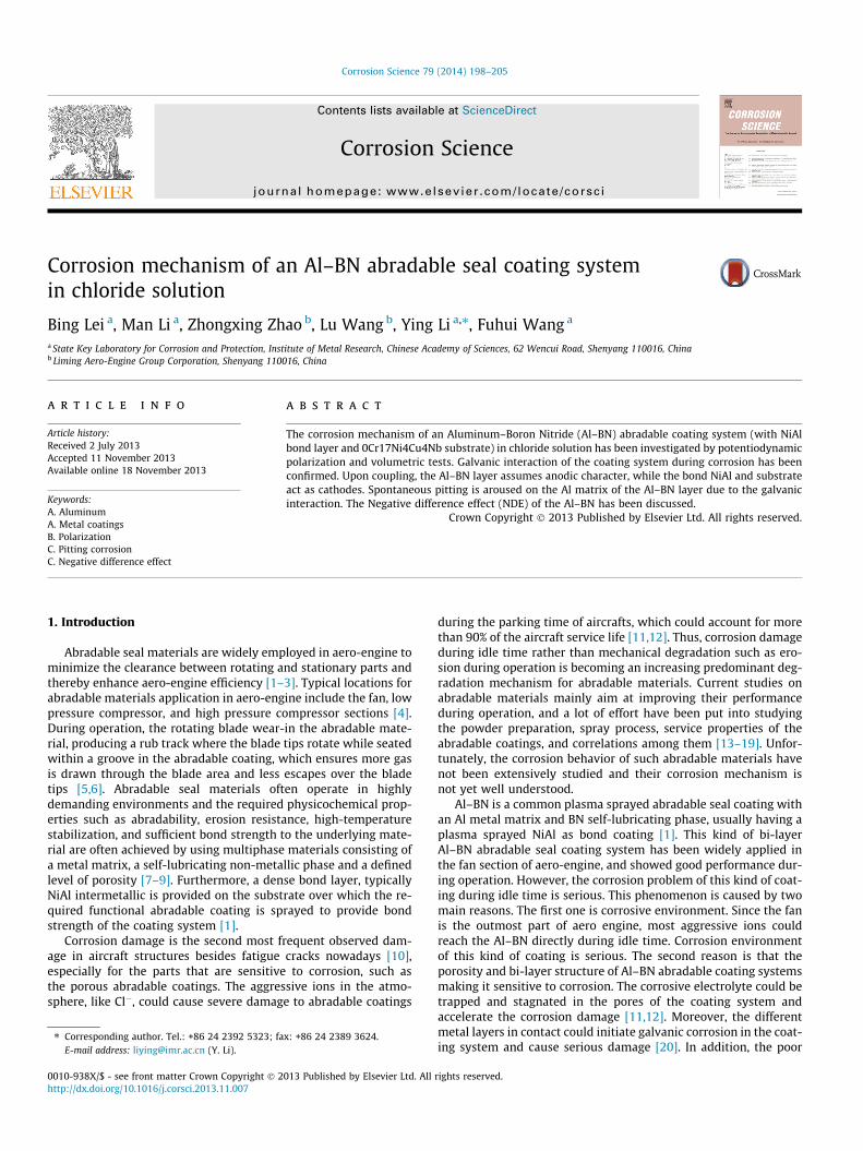
All electrochemical tests were carried out in 5 wt.% NaCl solu-tion using an AUTOLAB Electrochemical Measurement System, ina three electrode cell with a standard calomel electrode (SCE) asreference electrode and a platinum counter electrode. Workingelectrodes of the porous coating system and individual layers weredesigned specially to ensure the correctness of the results. For thecoating system, the as-sprayed materials were firstly cut into sam-ples of dimensions 10 mm � 10 mm, connected to a Cu lead wireon the uncoated side of the substrate, and then mounted by anepoxy powder coating. The epoxy powders were supplied by Har-bin Engineering University [32]. In the epoxy powder mountingprocess, the connected samples were firstly heated to 150 �C, andthen brought in contact the epoxy powders, which adhered tothe heated surface of the samples. After obtaining a uniform cover-age of the powder, the coated specimens were then placed in anoven for curing at 180 �C for 1 min. Lastly, the treated specimenswere embedded in epoxy resin, with the pre-formed powder coat-ing preventing penetration of the uncured liquid epoxy resin intothe porous electrodes. The as-prepared electrode is illustrated inFig. 1.
The individual Al–BN and NiAl samples were connected to a Cuwire, wrapped with polytetrafluoroethylene tape and coated witha paraffin–rosin mixture, leaving an exposed working area of1 cm2. In order to avoid galvanic corrosion between the Cu wireand the sample resulting from the electrolyte reaching the con-necting area through pores of the layers, the set up was modifiedin such a way as to keep the connecting areas outside of the testsolution (Fig. 2). Samples were long enough to make sure electro-lyte cannot reach the connecting area by capillary action.
Prior to each electrochemical experiment, the samples werewet-ground to 1000 grit SiC paper, cleaned ultrasonically in dis-tilled water, degreased with acetone and dried in a compressedhot air flow. The test solution, 5 wt.% NaCl, was prepared from ana-lytical grade reagents and distilled water.
Fig. 1. Schematic diagram of the experimental design for the Al–BN coating systemworking electrode.
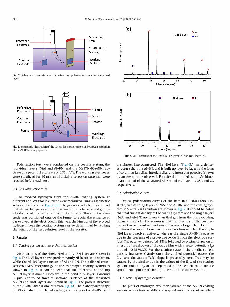
Fig. 2. Schematic illustration of the set-up for polarization tests for individuallayers.
Fig. 3. Schematic illustration of the set-up for measurement of hydrogen evolutionof the Al–BN coating system.
Fig. 4. XRD patterns of the single Al–BN layer (a) and NiAl layer (b).
200 B. Lei et al. / Corrosion Science 79 (2014) 198–205
Polarization tests were conducted on the coating system, theindividual layers (NiAl and Al–BN) and the 0Cr17Ni4Cu4Nb sub-strate at a potential scan rate of 0.33 mV/s. The working electrodeswere stabilized for 10 min until a stable corrosion potential werereached before each test.
2.3. Gas volumetric tests
The evolved hydrogen from the Al–BN coating system atdifferent applied anodic current were measured using a gasometricsetup as illustrated in Fig. 3 [33]. The gas was collected by a funneljust above the specimen, and then went into a burette and gradu-ally displaced the test solution in the burette. The counter elec-trode was positioned outside the funnel to avoid the entrance ofgas evolved at the electrode. In this way, the kinetics of the evolvedhydrogen from the coating system can be determined by readingthe height of the test solution level in the burette.
3. Results
3.1. Coating system structure characterization
XRD patterns of the single NiAl and Al–BN layer are shown inFig. 4. The NiAl layer shows predominantly Ni-based solid solution,while the Al–BN layer consists of Al and BN. The polished cross-sectional SEM morphology of the as-sprayed coating system isshown in Fig. 5. It can be seen that the thickness of the topAl–BN layer is about 1 mm while the bond NiAl layer is around50 lm. Controlled fracture sectional surfaces of the separatedAl–BN and NiAl layers are shown in Fig. 6. The porous structureof the Al–BN layer is obvious from Fig. 6a. The platelet-like shapeof BN distributed in the Al matrix, and pores in the Al–BN layer
are almost interconnected. The NiAl layer (Fig. 6b) has a denserstructure than the Al–BN, and is built up layer by layer in the formof columnar lamellae. Interlamellar and intersplat porosity (shownby arrows) can be observed. Porosity determined by the Archime-dean method of the separated Al–BN and NiAl layer is 28% and 2%respectively.
3.2. Polarization curves
Typical polarization curves of the bare 0Cr17Ni4Cu4Nb sub-strate, freestanding layers of NiAl and Al–BN, and the coating sys-tem in 5 wt.% NaCl solution are shown in Fig. 7. It should be notedthat real current density of the coating system and the single layers(NiAl and Al–BN) are lower than that got from the correspondingpolarization plots. The reason is that the porosity of the coatingsmakes the real working surfaces to be much larger than 1 cm2.
From the anodic branches, it can be observed that the singleNiAl layer dissolves actively, whereas the single Al–BN is passivedue to the presence of a protective oxide film on the electrode sur-face. The passive region of Al–BN is followed by pitting corrosion asa result of breakdown of the oxide film with a break potential (Ep)around �0.75 V/SCE. For the coating system, the anodic currentdensity increases sharply once the applied potential passes theEcorr and the anodic Tafel slope is practically zero. This may becaused by the similarities in the values of the Ecorr of the coatingsystem and the Ep of the separated Al–BN, which could inducespontaneous pitting of the top Al–BN in the coating system.
3.3. Kinetics of hydrogen evolution
The plots of hydrogen evolution volume of the Al–BN coatingsystem versus time at different applied anodic current are illus-
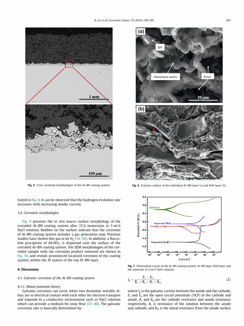
Fig. 5. Cross sectional morphologies of the Al–BN coating system.
(a)
(b)
BN
Aluminium matrix Pores
Fig. 6. Fracture surface of the individual Al–BN layer (a) and NiAl layer (b).
Fig. 7. Polarization curves of the Al–BN coating system, Al–BN layer, NiAl layer andthe substrate in 5 wt.% NaCl solution.
B. Lei et al. / Corrosion Science 79 (2014) 198–205 201
trated in Fig. 8. It can be observed that the hydrogen evolution rateincreases with increasing anodic current.
3.4. Corrosion morphologies
Fig. 9 presents the in situ macro surface morphology of thecorroded Al–BN coating system after 72 h immersion in 5 wt.%NaCl solution. Bubbles on the surface indicate that the corrosionof Al–BN coating system includes a gas generation step. Previousstudies have shown this gas to be H2 [34–36]. In addition, a floccu-lent precipitate of Al(OH)3 is dispersed over the surface of thecorroded Al–BN coating system. The SEM morphologies of the cor-roded sample with the corrosion product removed are shown inFig. 10, and reveals pronounced localized corrosion of the coatingsystem, within the Al matrix of the top Al–BN layer.
4. Discussion
4.1. Galvanic corrosion of the Al–BN coating system
4.1.1. Mixed potential theoryGalvanic corrosion can occur when two dissimilar metallic al-
loys are in electrical contact with each other for electron transportand exposed to a conductive environment such as NaCl solutionwhich can provide a medium for ionic flow [37–40]. The galvaniccorrosion rate is basically determined by:
ig ¼Ec � Ea
Rc þ Ra þ Rs þ Rmð2Þ
where ig is the galvanic current between the anode and the cathode,Ec and Ea are the open circuit potentials (OCP) of the cathode andanode, Rc and Ra are the cathode resistance and anode resistancerespectively, Rs is resistance of the solution between the anodeand cathode, and Rm is the metal resistance from the anode surface
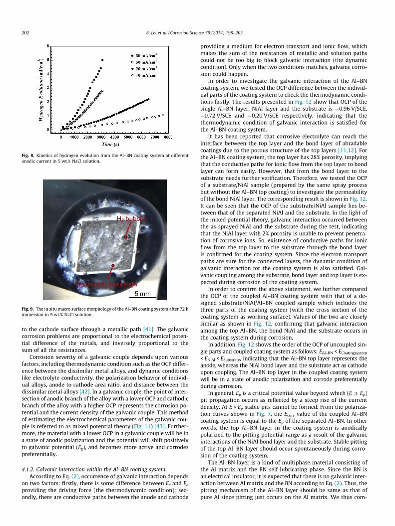
Fig. 8. Kinetics of hydrogen evolution from the Al–BN coating system at differentanodic current in 5 wt.% NaCl solution.
Fig. 9. The in situ macro surface morphology of the Al–BN coating system after 72 himmersion in 5 wt.% NaCl solution.
202 B. Lei et al. / Corrosion Science 79 (2014) 198–205
to the cathode surface through a metallic path [41]. The galvaniccorrosion problems are proportional to the electrochemical poten-tial difference of the metals, and inversely proportional to thesum of all the resistances.
Corrosion severity of a galvanic couple depends upon variousfactors, including thermodynamic condition such as the OCP differ-ence between the dissimilar metal alloys, and dynamic conditionslike electrolyte conductivity, the polarization behavior of individ-ual alloys, anode to cathode area ratio, and distance between thedissimilar metal alloys [42]. In a galvanic couple, the point of inter-section of anodic branch of the alloy with a lower OCP and cathodicbranch of the alloy with a higher OCP represents the corrosion po-tential and the current density of the galvanic couple. This methodof estimating the electrochemical parameters of the galvanic cou-ple is referred to as mixed potential theory (Fig. 11) [43]. Further-more, the material with a lower OCP in a galvanic couple will be ina state of anodic polarization and the potential will shift positivelyto galvanic potential (Eg), and becomes more active and corrodespreferentially.
4.1.2. Galvanic interaction within the Al–BN coating systemAccording to Eq. (2), occurrence of galvanic interaction depends
on two factors: firstly, there is some difference between Ec and Ea
providing the driving force (the thermodynamic condition); sec-ondly, there are conductive paths between the anode and cathode
providing a medium for electron transport and ionic flow, whichmakes the sum of the resistances of metallic and solution pathscould not be too big to block galvanic interaction (the dynamiccondition). Only when the two conditions matches, galvanic corro-sion could happen.
In order to investigate the galvanic interaction of the Al–BNcoating system, we tested the OCP difference between the individ-ual parts of the coating system to check the thermodynamic condi-tions firstly. The results presented in Fig. 12 show that OCP of thesingle Al–BN layer, NiAl layer and the substrate is �0.96 V/SCE,�0.72 V/SCE and �0.20 V/SCE respectively, indicating that thethermodynamic condition of galvanic interaction is satisfied forthe Al–BN coating system.
It has been reported that corrosive electrolyte can reach theinterface between the top layer and the bond layer of abradablecoatings due to the porous structure of the top layers [11,12]. Forthe Al–BN coating system, the top layer has 28% porosity, implyingthat the conductive paths for ionic flow from the top layer to bondlayer can form easily. However, that from the bond layer to thesubstrate needs further verification. Therefore, we tested the OCPof a substrate/NiAl sample (prepared by the same spray processbut without the Al–BN top coating) to investigate the permeabilityof the bond NiAl layer. The corresponding result is shown in Fig. 12.It can be seen that the OCP of the substrate/NiAl sample lies be-tween that of the separated NiAl and the substrate. In the light ofthe mixed potential theory, galvanic interaction occurred betweenthe as-sprayed NiAl and the substrate during the test, indicatingthat the NiAl layer with 2% porosity is unable to prevent penetra-tion of corrosive ions. So, existence of conductive paths for ionicflow from the top layer to the substrate through the bond layeris confirmed for the coating system. Since the electron transportpaths are sure for the connected layers, the dynamic condition ofgalvanic interaction for the coating system is also satisfied. Gal-vanic coupling among the substrate, bond layer and top layer is ex-pected during corrosion of the coating system.
In order to confirm the above statement, we further comparedthe OCP of the coupled Al–BN coating system with that of a de-signed substrate/NiAl/Al–BN coupled sample which includes thethree parts of the coating system (with the cross section of thecoating system as working surface). Values of the two are closelysimilar as shown in Fig. 12, confirming that galvanic interactionamong the top Al–BN, the bond NiAl and the substrate occurs inthe coating system during corrosion.
In addition, Fig. 12 shows the order of the OCP of uncoupled sin-gle parts and coupled coating system as follows: EAl–BN < ECoatingsystem
< ENiAl < ESubstrate, indicating that the Al–BN top layer represents theanode, whereas the NiAl bond layer and the substrate act as cathodeupon coupling. The Al–BN top layer in the coupled coating systemwill be in a state of anodic polarization and corrode preferentiallyduring corrosion.
In general, Ep is a critical potential value beyond which (E P Ep)pit propagation occurs as reflected by a steep rise of the currentdensity. At E < Ep stable pits cannot be formed. From the polariza-tion curves shown in Fig. 7, the Ecorr value of the coupled Al–BNcoating system is equal to the Ep of the separated Al–BN. In otherwords, the top Al–BN layer in the coating system is anodicallypolarized to the pitting potential range as a result of the galvanicinteractions of the NiAl bond layer and the substrate. Stable pittingof the top Al–BN layer should occur spontaneously during corro-sion of the coating system.
The Al–BN layer is a kind of multiphase material consisting ofthe Al matrix and the BN self-lubricating phase. Since the BN isan electrical insulator, it is expected that there is no galvanic inter-action between Al matrix and the BN according to Eq. (2). Thus, thepitting mechanism of the Al–BN layer should be same as that ofpure Al since pitting just occurs on the Al matrix. We thus com-
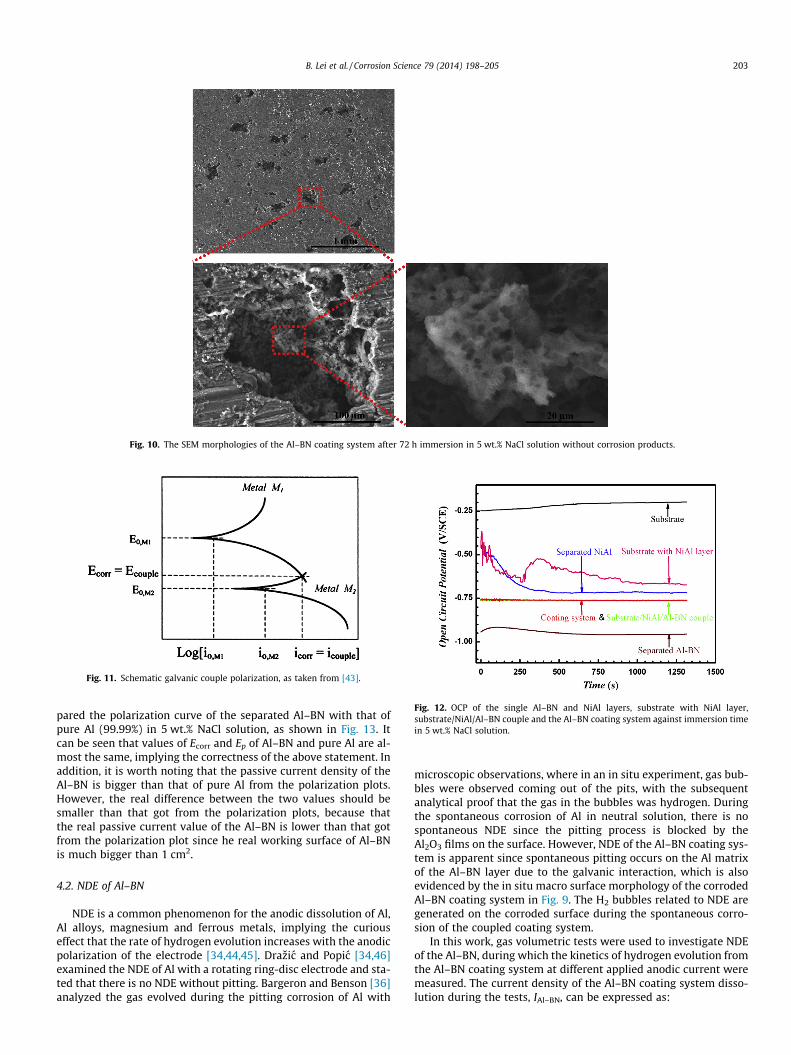
Fig. 10. The SEM morphologies of the Al–BN coating system after 72 h immersion in 5 wt.% NaCl solution without corrosion products.
Fig. 11. Schematic galvanic couple polarization, as taken from [43].
Fig. 12. OCP of the single Al–BN and NiAl layers, substrate with NiAl layer,substrate/NiAl/Al–BN couple and the Al–BN coating system against immersion timein 5 wt.% NaCl solution.
B. Lei et al. / Corrosion Science 79 (2014) 198–205 203
pared the polarization curve of the separated Al–BN with that ofpure Al (99.99%) in 5 wt.% NaCl solution, as shown in Fig. 13. Itcan be seen that values of Ecorr and Ep of Al–BN and pure Al are al-most the same, implying the correctness of the above statement. Inaddition, it is worth noting that the passive current density of theAl–BN is bigger than that of pure Al from the polarization plots.However, the real difference between the two values should besmaller than that got from the polarization plots, because thatthe real passive current value of the Al–BN is lower than that gotfrom the polarization plot since he real working surface of Al–BNis much bigger than 1 cm2.
4.2. NDE of Al–BN
NDE is a common phenomenon for the anodic dissolution of Al,Al alloys, magnesium and ferrous metals, implying the curiouseffect that the rate of hydrogen evolution increases with the anodicpolarization of the electrode [34,44,45]. Drazic and Popic [34,46]examined the NDE of Al with a rotating ring-disc electrode and sta-ted that there is no NDE without pitting. Bargeron and Benson [36]analyzed the gas evolved during the pitting corrosion of Al with
microscopic observations, where in an in situ experiment, gas bub-bles were observed coming out of the pits, with the subsequentanalytical proof that the gas in the bubbles was hydrogen. Duringthe spontaneous corrosion of Al in neutral solution, there is nospontaneous NDE since the pitting process is blocked by theAl2O3 films on the surface. However, NDE of the Al–BN coating sys-tem is apparent since spontaneous pitting occurs on the Al matrixof the Al–BN layer due to the galvanic interaction, which is alsoevidenced by the in situ macro surface morphology of the corrodedAl–BN coating system in Fig. 9. The H2 bubbles related to NDE aregenerated on the corroded surface during the spontaneous corro-sion of the coupled coating system.
In this work, gas volumetric tests were used to investigate NDEof the Al–BN, during which the kinetics of hydrogen evolution fromthe Al–BN coating system at different applied anodic current weremeasured. The current density of the Al–BN coating system disso-lution during the tests, IAl–BN, can be expressed as:
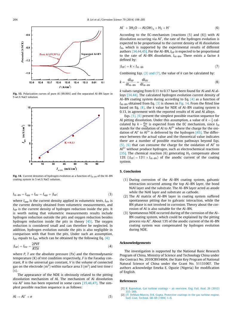
Fig. 13. Polarization curves of pure Al (99.99%) and the separated Al–BN layer in5 wt.% NaCl solution.
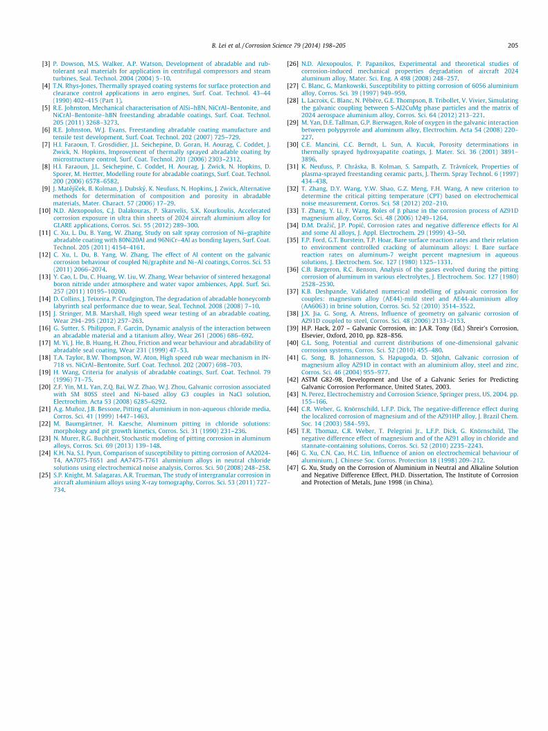
Fig. 14. Current densities of hydrogen evolution as a function of IAl–BN of the Al–BNcoating system in 5 wt.% NaCl solution.
204 B. Lei et al. / Corrosion Science 79 (2014) 198–205
IAl�BN ¼ Iapp þ IHV ¼ Iapp þ jIHPj ð3Þ
where Iapp is the current density applied in volumetric tests, IHV isthe current density obtained from volumetric measurements, andIHP is the current density of hydrogen reduction inside the pits. Itis worth noting that volumetric measurements results includehydrogen reduction outside the pits and oxygen reduction besideshydrogen reduction inside the pits in theory [45]. The oxygenreduction is considered small and can therefore be neglected. Inaddition, hydrogen evolution outside the pits is also negligible incomparison with that from the pits. Under such an assumption,IHV equals to IHP, which can be obtained by the following Eq. (4):
jIHPj ¼ IHV ¼2PVFRTSt
ð4Þ
where P, T are the absolute pressure (Pa) and the thermodynamictemperature (K) of test condition respectively, F is the Faraday con-stant, R is the universal gas constant, V is the volume of connectedgas on the electrode (m3) within surface area S (m2) and test time t(s).
The appearance of the NDE is obviously related to the pittingdissolution mechanism of Al. The mechanism of Al dissolutionvia Al+ ions has been reported in some cases [35,46,47]. The sim-plest possible reaction sequence is as follows:
Al! Alþ þ e ð5Þ
Alþ þ 3H2O! AlðOHÞ3 þH2 þHþ ð6Þ
According to the EC-mechanism (reactions (5) and (6)) with Aldissolution occurring via Al+, the rate of the hydrogen evolution isexpected to be proportional to the current density of Al dissolutionIAl, which is supported by the experimental results of differentauthors [34,44,45]. For the Al–BN, IHP is expected to be proportionalto the rate of Al–BN dissolution, IAl–BN. There exists a factor kdefined by:
jIHPj ¼ k� IAl�BN ð7Þ
Combining Eqs. (3) and (7), the value of k can be calculated by:
k ¼ dIHP
dIAl—BN¼ dIHV
dIAl—BNð8Þ
k values ranging from 0.11 to 0.17 have been found for Al and Al al-loys [34,44]. The calculated hydrogen evolution current density ofAl–BN coating system during according to Eq. (4) as a function ofIAl–BN obtained from Eq. (3) is shown in Fig. 14. From the fitted linebased on Eq. (8), the k value for NDE of Al–BN coating system is0.13, in agreement with the reported results of Al and Al alloys.
Eqs. (5), (6) present the simplest possible reaction sequence forAl pitting dissolution. Under this assumption, a value of k ¼ 2
3 cal-culated by k ¼ dIHP
dIAlis expected from the EC mechanism, since IAl
stands for the oxidation of Al to Al3+ where the charge for the oxi-dation of Al+ to Al3+ is delivered by the hydrogen [45]. The differ-ence between the actual value and the theoretical value indicatesthere are a number of possible reaction pathways beyond Eqs.(5), (6) that can consume the charge for the oxidation of Al+ toAl3+ without produce hydrogen, such as electrochemical reactions[35]. The chemical reaction (6) generating H2 compensate about13% (jIHPj ¼ 13%� IAl—BN) of the anodic current of the coatingsystem.
5. Conclusion
(1) During corrosion of the Al–BN coating system, galvanicinteraction occurred among the top Al–BN layer, the bondNiAl layer and the substrate. The Al–BN layer acted as anodewhile the NiAl layer and substrate as cathode.
(2) The Al matrix of Al–BN layer in coating system sufferedspontaneous pitting due to galvanic interaction, while theBN phase is not involved in corrosion. Theory about the cor-rosion of Al is also suitable for the Al–BN.
(3) Spontaneous NDE occurred during of the corrosion of the Al–BN coating system, which could be explained by the pittingprocess via Al+. About 13% of the anodic current of the Al–BNcoating system was compensated by hydrogen evolutionduring NDE.
Acknowledgements
The investigation is supported by the National Basic ResearchProgram of China, Ministry of Science and Technology China underthe Contract No. 2010CB934604, the State Key Program of NationalNatural Science of China under the Grant No. 51131007. Theauthors acknowledge Emeka E. Oguzie (Nigeria) for modificationof English.
References
[1] R. Rajendran, Gas turbine coatings – an overview, Eng. Fail. Anal. 26 (2012)355–369.
[2] J.T. DeMasi-Marcin, D.K. Gupta, Protective coatings in the gas turbine engine,Surf. Coat. Technol. 68–69 (1994) 1–9.
B. Lei et al. / Corrosion Science 79 (2014) 198–205 205
[3] P. Dowson, M.S. Walker, A.P. Watson, Development of abradable and rub-tolerant seal materials for application in centrifugal compressors and steamturbines, Seal. Technol. 2004 (2004) 5–10.
[4] T.N. Rhys-Jones, Thermally sprayed coating systems for surface protection andclearance control applications in aero engines, Surf. Coat. Technol. 43–44(1990) 402–415 (Part 1).
[5] R.E. Johnston, Mechanical characterisation of AlSi–hBN, NiCrAl–Bentonite, andNiCrAl–Bentonite–hBN freestanding abradable coatings, Surf. Coat. Technol.205 (2011) 3268–3273.
[6] R.E. Johnston, W.J. Evans, Freestanding abradable coating manufacture andtensile test development, Surf. Coat. Technol. 202 (2007) 725–729.
[7] H.I. Faraoun, T. Grosdidier, J.L. Seichepine, D. Goran, H. Aourag, C. Coddet, J.Zwick, N. Hopkins, Improvement of thermally sprayed abradable coating bymicrostructure control, Surf. Coat. Technol. 201 (2006) 2303–2312.
[8] H.I. Faraoun, J.L. Seichepine, C. Coddet, H. Aourag, J. Zwick, N. Hopkins, D.Sporer, M. Hertter, Modelling route for abradable coatings, Surf. Coat. Technol.200 (2006) 6578–6582.
[9] J. Matejícek, B. Kolman, J. Dubsky, K. Neufuss, N. Hopkins, J. Zwick, Alternativemethods for determination of composition and porosity in abradablematerials, Mater. Charact. 57 (2006) 17–29.
[10] N.D. Alexopoulos, C.J. Dalakouras, P. Skarvelis, S.K. Kourkoulis, Acceleratedcorrosion exposure in ultra thin sheets of 2024 aircraft aluminium alloy forGLARE applications, Corros. Sci. 55 (2012) 289–300.
[11] C. Xu, L. Du, B. Yang, W. Zhang, Study on salt spray corrosion of Ni–graphiteabradable coating with 80Ni20Al and 96NiCr–4Al as bonding layers, Surf. Coat.Technol. 205 (2011) 4154–4161.
[12] C. Xu, L. Du, B. Yang, W. Zhang, The effect of Al content on the galvaniccorrosion behaviour of coupled Ni/graphite and Ni–Al coatings, Corros. Sci. 53(2011) 2066–2074.
[13] Y. Cao, L. Du, C. Huang, W. Liu, W. Zhang, Wear behavior of sintered hexagonalboron nitride under atmosphere and water vapor ambiences, Appl. Surf. Sci.257 (2011) 10195–10200.
[14] D. Collins, J. Teixeira, P. Crudgington, The degradation of abradable honeycomblabyrinth seal performance due to wear, Seal. Technol. 2008 (2008) 7–10.
[15] J. Stringer, M.B. Marshall, High speed wear testing of an abradable coating,Wear 294–295 (2012) 257–263.
[16] G. Sutter, S. Philippon, F. Garcin, Dynamic analysis of the interaction betweenan abradable material and a titanium alloy, Wear 261 (2006) 686–692.
[17] M. Yi, J. He, B. Huang, H. Zhou, Friction and wear behaviour and abradability ofabradable seal coating, Wear 231 (1999) 47–53.
[18] T.A. Taylor, B.W. Thompson, W. Aton, High speed rub wear mechanism in IN-718 vs. NiCrAl–Bentonite, Surf. Coat. Technol. 202 (2007) 698–703.
[19] H. Wang, Criteria for analysis of abradable coatings, Surf. Coat. Technol. 79(1996) 71–75.
[20] Z.F. Yin, M.L. Yan, Z.Q. Bai, W.Z. Zhao, W.J. Zhou, Galvanic corrosion associatedwith SM 80SS steel and Ni-based alloy G3 couples in NaCl solution,Electrochim. Acta 53 (2008) 6285–6292.
[21] A.g. Muñoz, J.B. Bessone, Pitting of aluminium in non-aqueous chloride media,Corros. Sci. 41 (1999) 1447–1463.
[22] M. Baumgärtner, H. Kaesche, Aluminum pitting in chloride solutions:morphology and pit growth kinetics, Corros. Sci. 31 (1990) 231–236.
[23] N. Murer, R.G. Buchheit, Stochastic modeling of pitting corrosion in aluminumalloys, Corros. Sci. 69 (2013) 139–148.
[24] K.H. Na, S.I. Pyun, Comparison of susceptibility to pitting corrosion of AA2024-T4, AA7075-T651 and AA7475-T761 aluminium alloys in neutral chloridesolutions using electrochemical noise analysis, Corros. Sci. 50 (2008) 248–258.
[25] S.P. Knight, M. Salagaras, A.R. Trueman, The study of intergranular corrosion inaircraft aluminium alloys using X-ray tomography, Corros. Sci. 53 (2011) 727–734.
[26] N.D. Alexopoulos, P. Papanikos, Experimental and theoretical studies ofcorrosion-induced mechanical properties degradation of aircraft 2024aluminum alloy, Mater. Sci. Eng. A 498 (2008) 248–257.
[27] C. Blanc, G. Mankowski, Susceptibility to pitting corrosion of 6056 aluminiumalloy, Corros. Sci. 39 (1997) 949–959.
[28] L. Lacroix, C. Blanc, N. Pébère, G.E. Thompson, B. Tribollet, V. Vivier, Simulatingthe galvanic coupling between S-Al2CuMg phase particles and the matrix of2024 aerospace aluminium alloy, Corros. Sci. 64 (2012) 213–221.
[29] M. Yan, D.E. Tallman, G.P. Bierwagen, Role of oxygen in the galvanic interactionbetween polypyrrole and aluminum alloy, Electrochim. Acta 54 (2008) 220–227.
[30] C.E. Mancini, C.C. Berndt, L. Sun, A. Kucuk, Porosity determinations inthermally sprayed hydroxyapatite coatings, J. Mater. Sci. 36 (2001) 3891–3896.
[31] K. Neufuss, P. Chráska, B. Kolman, S. Sampath, Z. Trávnícek, Properties ofplasma-sprayed freestanding ceramic parts, J. Therm. Spray Technol. 6 (1997)434–438.
[32] T. Zhang, D.Y. Wang, Y.W. Shao, G.Z. Meng, F.H. Wang, A new criterion todetermine the critical pitting temperature (CPT) based on electrochemicalnoise measurement, Corros. Sci. 58 (2012) 202–210.
[33] T. Zhang, Y. Li, F. Wang, Roles of b phase in the corrosion process of AZ91Dmagnesium alloy, Corros. Sci. 48 (2006) 1249–1264.
[34] D.M. Drazic, J.P. Popic, Corrosion rates and negative difference effects for Aland some Al alloys, J. Appl. Electrochem. 29 (1999) 43–50.
[35] F.P. Ford, G.T. Burstein, T.P. Hoar, Bare surface reaction rates and their relationto environment controlled cracking of aluminum alloys: I. Bare surfacereaction rates on aluminum-7 weight percent magnesium in aqueoussolutions, J. Electrochem. Soc. 127 (1980) 1325–1331.
[36] C.B. Bargeron, R.C. Benson, Analysis of the gases evolved during the pittingcorrosion of aluminum in various electrolytes, J. Electrochem. Soc. 127 (1980)2528–2530.
[37] K.B. Deshpande, Validated numerical modelling of galvanic corrosion forcouples: magnesium alloy (AE44)-mild steel and AE44-aluminium alloy(AA6063) in brine solution, Corros. Sci. 52 (2010) 3514–3522.
[38] J.X. Jia, G. Song, A. Atrens, Influence of geometry on galvanic corrosion ofAZ91D coupled to steel, Corros. Sci. 48 (2006) 2133–2153.
[39] H.P. Hack, 2.07 – Galvanic Corrosion, in: J.A.R. Tony (Ed.) Shreir’s Corrosion,Elsevier, Oxford, 2010, pp. 828–856.
[40] G.L. Song, Potential and current distributions of one-dimensional galvaniccorrosion systems, Corros. Sci. 52 (2010) 455–480.
[41] G. Song, B. Johannesson, S. Hapugoda, D. StJohn, Galvanic corrosion ofmagnesium alloy AZ91D in contact with an aluminium alloy, steel and zinc,Corros. Sci. 46 (2004) 955–977.
[42] ASTM G82-98, Development and Use of a Galvanic Series for PredictingGalvanic Corrosion Performance, United States, 2003.
[43] N. Perez, Electrochemistry and Corrosion Science, Springer press, US, 2004. pp.155–166.
[44] C.R. Weber, G. Knörnschild, L.F.P. Dick, The negative-difference effect duringthe localized corrosion of magnesium and of the AZ91HP alloy, J. Brazil Chem.Soc. 14 (2003) 584–593.
[45] T.R. Thomaz, C.R. Weber, T. Pelegrini Jr., L.F.P. Dick, G. Knörnschild, Thenegative difference effect of magnesium and of the AZ91 alloy in chloride andstannate-containing solutions, Corros. Sci. 52 (2010) 2235–2243.
[46] G. Xu, C.N. Cao, H.C. Lin, Influence of anion on electrochemical behaviour ofaluminium, J. Chinese Soc. Corros. Protection 18 (1998) 209–212.
[47] G. Xu, Study on the Corrosion of Aluminium in Neutral and Alkaline Solutionand Negative Difference Effect, PH.D. Dissertation, The Institute of Corrosionand Protection of Metals, June 1998 (in China).