Embed Size (px)
Citation preview

metals
Article
Corrosion Resistance Properties of AluminumCoating Applied by Arc Thermal Metal Spray in SAEJ2334 Solution with Exposure Periods
Han-Seung Lee 1, Jitendra Kumar Singh 1,2, Mohamed A. Ismail 3,* and Chinmoy Bhattacharya 2
1 Department of Architectural Engineering, Hanyang University, 1271 Sa 3-dong, Sangrok-gu, Ansan 426-791,Korea; [email protected] (H.-S.L.); [email protected] (J.K.S.)
2 Department of Chemistry, Indian Institute of Engineering Science and Technology, Shibpur, Howrah 711103,India; [email protected]
3 Department of Civil and Construction Engineering, Faculty of Engineering and Science, Curtin UniversitySarawak, CDT 250, 98009 Miri, Malaysia
* Correspondence: [email protected]; Tel.: +60-85-443939 (ext. 3962); Fax: +60-85-443837
Academic Editor: Hugo F. LopezReceived: 31 December 2015; Accepted: 26 February 2016; Published: 5 March 2016
Abstract: Arc thermal metal spray coating provides excellent corrosion, erosion and wear resistanceto steel substrates. This paper incorporates some results of aluminum coating applied by this methodon plain carbon steel. Thereafter, coated panels were exposed to an environment known to form stablecorrosion products with aluminum. The coated panels were immersed in Society of AutomotiveEngineers (SAE) J2334 for different periods of time. This solution consists of an aqueous solutionof NaCl, CaCl2 and NaHCO3. Various electrochemical techniques, i.e., corrosion potential-time,electrochemical impedance spectroscopy (EIS) and the potentiodynamic were used to determine theperformance of stimulants in improving the properties of the coating. EIS studies revealed the kineticsand mechanism of corrosion and potentiodynamic attributed the formation of a passive film, whichstifles the penetration of aggressive ions towards the substrate. The corrosion products that formedon the coating surface, identified using Raman spectroscopy, were Dawsonite (NaAlCO3(OH)2) andAl(OH)3. These compounds of aluminum are very sparingly soluble in aqueous solution and protectthe substrate from pitting and uniform corrosion. The morphology and composition of corrosionproducts determined by scanning electron microscopy and energy dispersive X-ray analyses indicatedthat the environment plays a decisive role in improving the corrosion resistance of aluminum coating.
Keywords: passive film; arc thermal metal spray; electrochemical impedance spectroscopy; Ramanspectroscopy; SEM; X-ray diffraction
1. Introduction
Steel is being used everywhere in world due to its broad application. Steel has inherent mechanicalproperties to a proper extent, but there are some problems related to corrosion, especially in aqueous,dry and atmospheric conditions. The atmospheric corrosion of steel is a serious problem and differenttypes of organic and inorganic coatings have been developed to extend the service life of structuresmade from steel. Besides coatings on structural steel, stainless steel is being used in infrastructurebut is not economical. The coating of steel with aluminum metal is found to provide protection inindustrial and marine environments. Different techniques for the application of aluminum coatingsuch as hot dip, aluminizing, high velocity oxy fuel, plasma spray and arc thermal spray methods,have been developed. Among these techniques, arc thermal spray methods are convenient, economicaland logistically feasible [1,2]. To protect bridges, strobes, pipelines and other large steel structures forlong-term protection in industrially polluted, saline and open atmospheres, the use of Al coating with
Metals 2016, 6, 55; doi:10.3390/met6030055 www.mdpi.com/journal/metals

Metals 2016, 6, 55 2 of 15
the thermal spray process had been reported about a century ago [3]. The application of coatings withthe arc thermal process is very easy and convenient. In this process, prior to the application of thecoating, the target surface should be proper cleaned and sandblasted because a good anchoring forthe coating is required. This instrument gun is portable and a power supply is needed for the arcingof wires. Before applying the coating, it must be ensured that there is a proper power supply at theapplication location and a fuel tank necessary for the flame spray. In the arc thermal metals sprayprocess, twin wires are used for coating and an electric arc melts the tips of these wires. After arcing,the wires melt and atomized by hot air which impinges on the target (substrate). The melted metaldroplets adhere onto the substrates and are cooled at room temperature, resulting in the formation of acoating [4]. Due to the high speed of spraying and the sudden cooling of melted metal droplets spreadat the substrate, some invisible porosity in the deposited coating and shrinkages develops [1,5–8].
To fill the pores or defects in coatings, various methods have been suggested. The most popularmethod is metal-polymeric dual coating. The application of polymeric coating is better for shorterdurations of exposure with regard to corrosion protection. In the case of longer durations, it causescracking or premature distresses in the coating. It is caused due to a difference in the thermal expansioncoefficients of the metal-polymer. Li et al. (2006) and Muhamad et al. (2013) have carried out researchinto the protection of steel by means of Al coating through an arc thermal spray process with a filler;they reported enhanced corrosion resistance properties for this coating after eight years of exposure ina coastal environment [9,10].
A search of the literature reveals that very limited information is available on the use of fillersor other techniques to block the porosity of arc thermal sprayed aluminum coating. To enhancethe properties of coatings, researchers are using different pseudo alloys and rare earth metals forcorrosion resistance properties in aggressive environments [11,12]. Due to the anodic nature ofAl metal, it sacrificially protects the steel surface. During the corrosion process of the Al coating,its corrosion products are deposited on the coating surface. These corrosion products fill the pores ofthe coating and enhances the corrosion resistance performance of the Al coating by arc thermal sprayprocess. The most popular test environment to assess the performance of the coatings is 3.5 wt. %sodium chloride. The corrosion performance of Al coatings in coastal and open industrially pollutedenvironments showed the enhanced corrosion resistance properties for longer duration of exposure dueto the sacrificial nature of Al metal [13] and the formation of naturally occurring protective corrosionproducts on the coating surface [14]. These protective corrosion products block the pores of the coatingand increase the corrosion resistance properties of the coating. For studies on atmospheric corrosion,the coating should be exposed for longer durations to assess its corrosion resistance properties [15].
A search of the literature also shows that there is possibly no such research being carried outby anyone to study the performance of Al coatings in the laboratory in the presence of stimulants.Generally, stimulants are induced in nature for the corrosion of metals and alloys. In the atmosphere,there are many stimulants present, i.e., carbonates, chlorides, sulphates, nitrates, etc. The atmosphericcorrosion for coated samples requires a significant amount of time to determine their performance anddepends on the aggressiveness of the environment [15]. However, this study simulates the aggressiveatmospheric environment to form naturally occurring corrosion products to block the pores of thecoating in immersion conditions. We allowed the deposited coating to age in an environment having alower concentration of sodium chloride, sodium bicarbonate and calcium chloride. The idea was todevelop sparingly soluble corrosion products under immersion conditions and block the porosity inthe coating. The objectives of this study are as follows:
1. To evaluate the performance of Al coatings in immersion conditions of SAE J2334 solution;2. To determine the kinetics and mechanism of corrosion process for Al coatings applied by arc
thermal metals spray in the presence of stimulants, i.e., carbonate and chloride ions;3. To study the role of stimulants on the formation of corrosion products on the surface of Al
coatings in SAE J2334 solution;

Metals 2016, 6, 55 3 of 15
4. To study the nature of corrosion products formed on Al coating surface in presence of stimulants,i.e., carbonate and chloride ions.
2. Materials and Methods
2.1. Process of Coating
An arc thermal metal spray coating with commercially pure Al (99.95 wt. %) wires of 1.6 mmdiameter was applied to a sandblasted mild steel substrate. The chemical composition of the mild steelis shown in Table 1. The dimension of the samples was 80 mm ˆ 60 mm ˆ 1.0 mm. The thickness ofthe coating was measured using a non-destructive technique with Elcometer 456 at different places,and was approximately 100 µm (˘5 µm). The details of the spraying parameters are shown inTable 2 [16–18].
Table 1. Chemical composition of steel (wt. %).
Chemical Composition (wt. %)
C Si Mn P S Cu Cr Ni Fe0.240 0.260 0.950 0.016 0.008 0.020 0.040 0.030 balance
Table 2. Detail parameters used in the high frequency arc thermal metal spray process [16–18].
Parameters (unit) Quantitative Value
Air Pressure (bar) 4–6Spraying distance (cm) 15–25Spraying Voltage (V) 30Spraying Current (A) 200
In this method, Al metal is being melted at an arc point through a circular slit by hot airstream in which metal can be diffused and cooled at room temperature (Figure 1). The detail of thespraying parameters was maintained on the basis of earlier work done by different researchers [16–18].The diffused layer of coating was formed on the steel substrate. During the solidification anddiffusion of metals towards the steel substrate, some pores are being formed on the coating. Thepores are different sizes and contribute to getting moisture, oxygen and other aggressive ions fromthe atmosphere.
Metals 2016, 6, 55 3 of 15
4. To study the nature of corrosion products formed on Al coating surface in presence of
stimulants, i.e., carbonate and chloride ions.
2. Materials and Methods
2.1. Process of Coating
An arc thermal metal spray coating with commercially pure Al (99.95 wt. %) wires of 1.6 mm
diameter was applied to a sandblasted mild steel substrate. The chemical composition of the mild
steel is shown in Table 1. The dimension of the samples was 80 mm × 60 mm × 1.0 mm. The
thickness of the coating was measured using a non‐destructive technique with Elcometer 456 at
different places, and was approximately 100 μm (±5 μm). The details of the spraying parameters are
shown in Table 2 [16–18].
Table 1. Chemical composition of steel (wt. %).
Chemical Composition (wt. %)
C Si Mn P S Cu Cr Ni Fe
0.240 0.260 0.950 0.016 0.008 0.020 0.040 0.030 balance
Table 2. Detail parameters used in the high frequency arc thermal metal spray process [16–18].
Parameters (unit) Quantitative Value
Air Pressure (bar) 4–6 Spraying distance (cm) 15–25
Spraying Voltage (V) 30
Spraying Current (A) 200
In this method, Al metal is being melted at an arc point through a circular slit by hot air stream
in which metal can be diffused and cooled at room temperature (Figure 1). The detail of the
spraying parameters was maintained on the basis of earlier work done by different researchers [16–
18]. The diffused layer of coating was formed on the steel substrate. During the solidification and
diffusion of metals towards the steel substrate, some pores are being formed on the coating. The
pores are different sizes and contribute to getting moisture, oxygen and other aggressive ions from
the atmosphere.
Figure 1. Schematic diagram of the arc thermal metal spay process.
After the application of the coating on the steel substrate, the adhesion of the coating strength
was measured based on to ASTM D4541 [19].
Figure 1. Schematic diagram of the arc thermal metal spay process.
After the application of the coating on the steel substrate, the adhesion of the coating strengthwas measured based on to ASTM D4541 [19].

Metals 2016, 6, 55 4 of 15
2.2. Electrochemical Studies
The electrochemical studies were performed with the SAE J2334 (Society of Automotive Engineers)solution [20–24]. It consists of 0.5 wt. % NaCl, 0.1 wt. % CaCl2 and 0.075 wt. % NaHCO3. The Al coatingis directly immersed in the SAE J2334 solution and it is likely identical to atmospheric weatheringconditions, which contain chloride and carbonate ions in open industrially polluted environments.The chemicals used were of analytical grade. The pH of the SAE J2334 solution was measured atroom temperature and was 9.17. These chemicals were dissolved in double distilled water. Prior tothe start of the experiments, the samples were exposed to the solution and stabilized the potentialwith potentiostat. These studies were performed by three electrode systems where the coated sampleworked as a working electrode (WE), platinum wire as a counter electrode (CE) and silver-silverchloride as a reference electrode (RE). The electrochemical setup is shown in Figure 2. The sampleholder area of working electrode was 0.78 cm2 and it was fixed for all samples.
Metals 2016, 6, 55 4 of 15
2.2. Electrochemical Studies
The electrochemical studies were performed with the SAE J2334 (Society of Automotive
Engineers) solution [20–24]. It consists of 0.5 wt. % NaCl, 0.1 wt. % CaCl2 and
0.075 wt. % NaHCO3. The Al coating is directly immersed in the SAE J2334 solution and it is likely
identical to atmospheric weathering conditions, which contain chloride and carbonate ions in open
industrially polluted environments. The chemicals used were of analytical grade. The pH of the
SAE J2334 solution was measured at room temperature and was 9.17. These chemicals were
dissolved in double distilled water. Prior to the start of the experiments, the samples were exposed
to the solution and stabilized the potential with potentiostat. These studies were performed by
three electrode systems where the coated sample worked as a working electrode (WE), platinum
wire as a counter electrode (CE) and silver‐silver chloride as a reference electrode (RE). The
electrochemical setup is shown in Figure 2. The sample holder area of working electrode was
0.78 cm2 and it was fixed for all samples.
Figure 2. Schematic diagram of the electrochemical setup.
The electrochemical impedance spectroscopy (EIS) studies were carried out by changing the
frequency of 10 mV sinusoidal voltage from 100 kHz to 0.01 Hz. The DC polarization studies were
performed at a 1 mV/s scan rate from −0.4 V to +0.8 V Vs open circuit potential [11,25]. The
potentiostat was VersaSTAT (Princeton Applied Research, Oak Ridge, TN, USA) and data analysis
was carried out using Metrohm Autolab Nova 1.10 software (Ionenstrasse, Herisau, Switzerland) by
fitting the experimental data in the constant phase element (CPE) model. All electrochemical
studies were carried out at room temperature (27 ± 1 °C).
2.3. Characterization of Coating and Corrosion Products
The morphology of coating and corrosion products were determined by Scanning Electron
Microscope (SEM, Philips XL 30, North Billerica, MA, USA) operated at 15 kV, equipped with an
Energy Dispersive X‐ray Spectroscopy (EDS) tool for elemental analysis. Prior to taking the image
of the SEM, samples were coated with platinum to increase the conductivity and avoid the charging
effect of samples. The X‐ray diffraction (XRD, Philips X’Pert‐MPD, EA Almelo, The Netherland)
studies of the coating was performed by using Cu Kα radiation (λ = 1.54059 Å) generated at 40 kV
and 100 mA. The Raman spectroscopy (Renishaw RM 1000, Mercury Dr., Champaign, IL, USA) of
corrosion products was carried out by using a He‐Ne laser beam of 632.8 nm wavelength. The
power of the laser was kept at 10 mW to avoid the transformation of corrosion products due to the
heating effect. The collection time was 10 s and the ranges of Raman shift between 200 cm−1 and
3200 cm−1. The locations of the specimens to be studied were focused through an Olympus
microscope at a magnification of 20 (Mercury Dr., Champaign, IL, USA). The sample holder had a
motorized platform with Jokey (Mercury Dr., Champaign, IL, USA) in order to have fine focusing
and mapping at a desired location. Prior to the analysis of the samples, the instrument was
calibrated by using pure silicon at the peaks of 520 cm−1.
Figure 2. Schematic diagram of the electrochemical setup.
The electrochemical impedance spectroscopy (EIS) studies were carried out by changing thefrequency of 10 mV sinusoidal voltage from 100 kHz to 0.01 Hz. The DC polarization studies wereperformed at a 1 mV/s scan rate from´0.4 V to +0.8 V Vs open circuit potential [11,25]. The potentiostatwas VersaSTAT (Princeton Applied Research, Oak Ridge, TN, USA) and data analysis was carriedout using Metrohm Autolab Nova 1.10 software (Ionenstrasse, Herisau, Switzerland) by fitting theexperimental data in the constant phase element (CPE) model. All electrochemical studies were carriedout at room temperature (27 ˘ 1 ˝C).
2.3. Characterization of Coating and Corrosion Products
The morphology of coating and corrosion products were determined by Scanning ElectronMicroscope (SEM, Philips XL 30, North Billerica, MA, USA) operated at 15 kV, equipped with anEnergy Dispersive X-ray Spectroscopy (EDS) tool for elemental analysis. Prior to taking the imageof the SEM, samples were coated with platinum to increase the conductivity and avoid the chargingeffect of samples. The X-ray diffraction (XRD, Philips X’Pert-MPD, EA Almelo, The Netherland)studies of the coating was performed by using Cu Kα radiation (λ = 1.54059 Å) generated at 40 kVand 100 mA. The Raman spectroscopy (Renishaw RM 1000, Mercury Dr., Champaign, IL, USA) ofcorrosion products was carried out by using a He-Ne laser beam of 632.8 nm wavelength. The powerof the laser was kept at 10 mW to avoid the transformation of corrosion products due to the heatingeffect. The collection time was 10 s and the ranges of Raman shift between 200 cm´1 and 3200 cm´1.The locations of the specimens to be studied were focused through an Olympus microscope at amagnification of 20 (Mercury Dr., Champaign, IL, USA). The sample holder had a motorized platformwith Jokey (Mercury Dr., Champaign, IL, USA) in order to have fine focusing and mapping at a desiredlocation. Prior to the analysis of the samples, the instrument was calibrated by using pure silicon atthe peaks of 520 cm´1.
Metals 2016, 6, 55 5 of 15
3. Results and Discussion
3.1. Characterization of the Arc Thermal Sprayed Coatings
The coating was characterized by SEM and XRD. The top surface and cross section morphologyof the coating by the SEM are shown in Figure 3. This coating had many defects as shown bythe arrow marks (Figure 3a,b), which is a well-known feature for such coatings [6,8]. The meltedmetal particles continuously impinged on the base metals and formed layer upon layer of plate-likemicrostructures [26]. With the high velocity deposition of the coating and after rapid cooling at roomtemperature, the air diffused from the coating surface resulted in the formation of a splashed zone orpores/defects on the coating surface [27,28]. These splash zones contributed to getting moisture andother aggressive ions from the atmosphere [29,30]. A chemical analysis of the coating is shown in theEDS spectra (Figure 3c). On the surface of coating, 2.20 wt. % oxygen was present; this oxygen mighthave come during the spraying of the coating at high temperature and in-flight particles oxidationfrom the atmosphere [31].
Metals 2016, 6, 55 5 of 15
3. Results and Discussion
3.1. Characterization of the Arc Thermal Sprayed Coatings
The coating was characterized by SEM and XRD. The top surface and cross section
morphology of the coating by the SEM are shown in Figure 3. This coating had many defects as
shown by the arrow marks (Figure 3a,b), which is a well‐known feature for such coatings [6,8]. The
melted metal particles continuously impinged on the base metals and formed layer upon layer of
plate‐like microstructures [26]. With the high velocity deposition of the coating and after rapid
cooling at room temperature, the air diffused from the coating surface resulted in the formation of a
splashed zone or pores/defects on the coating surface [27,28]. These splash zones contributed to
getting moisture and other aggressive ions from the atmosphere [29,30]. A chemical analysis of the
coating is shown in the EDS spectra (Figure 3c). On the surface of coating, 2.20 wt. % oxygen was
present; this oxygen might have come during the spraying of the coating at high temperature and
in‐flight particles oxidation from the atmosphere [31].
Figure 3. SEM images (a) top surface, (b) cross section and (c) EDS of the Al coating by the arc
thermal metal spray process.
The XRD of the coating is shown in Figure 4 and, from this figure, it can be seen that after the
spraying of Al using the arc thermal metal spray process, pure Al is present. There is no other phase
present on the coating surface besides Al, because the oxygen concentration is very low and the
oxide phase which might be present is beyond the limit of XRD detection.
Figure 4. The XRD of aluminum coating using the arc thermal metal spray process.
The bond strength of the coating was measured and is presented in Table 3. The coating was
applied on a sandblasted surface for proper adhesion to the steel substrate. In this process, 40 mm ×
40 mm of selected dimensions of the coating substrate were used for the adhesion test. The bond
strength measurements were carried out for four samples, and the average was taken for all
samples. The average coating strength was 4.86 MPa and the adhesion also depends on the
Figure 3. SEM images (a) top surface, (b) cross section and (c) EDS of the Al coating by the arc thermalmetal spray process.
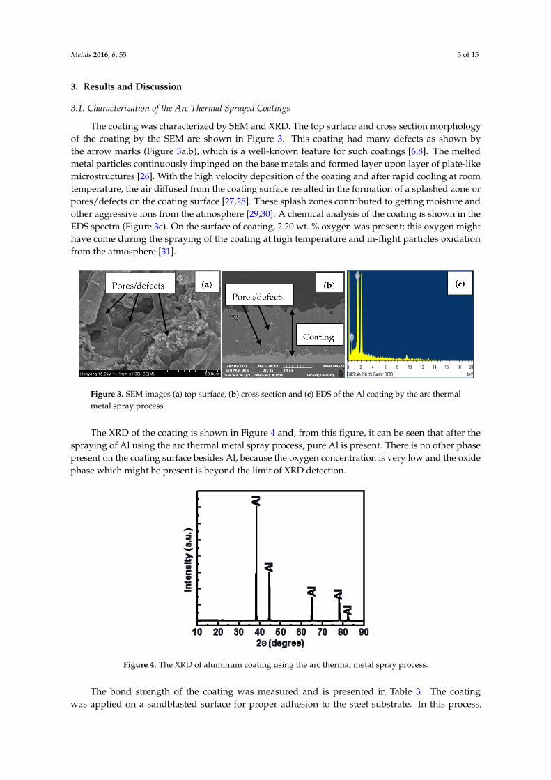
The XRD of the coating is shown in Figure 4 and, from this figure, it can be seen that after thespraying of Al using the arc thermal metal spray process, pure Al is present. There is no other phasepresent on the coating surface besides Al, because the oxygen concentration is very low and the oxidephase which might be present is beyond the limit of XRD detection.
Metals 2016, 6, 55 5 of 15
3. Results and Discussion
3.1. Characterization of the Arc Thermal Sprayed Coatings
The coating was characterized by SEM and XRD. The top surface and cross section
morphology of the coating by the SEM are shown in Figure 3. This coating had many defects as
shown by the arrow marks (Figure 3a,b), which is a well‐known feature for such coatings [6,8]. The
melted metal particles continuously impinged on the base metals and formed layer upon layer of
plate‐like microstructures [26]. With the high velocity deposition of the coating and after rapid
cooling at room temperature, the air diffused from the coating surface resulted in the formation of a
splashed zone or pores/defects on the coating surface [27,28]. These splash zones contributed to
getting moisture and other aggressive ions from the atmosphere [29,30]. A chemical analysis of the
coating is shown in the EDS spectra (Figure 3c). On the surface of coating, 2.20 wt. % oxygen was
present; this oxygen might have come during the spraying of the coating at high temperature and
in‐flight particles oxidation from the atmosphere [31].
Figure 3. SEM images (a) top surface, (b) cross section and (c) EDS of the Al coating by the arc
thermal metal spray process.
The XRD of the coating is shown in Figure 4 and, from this figure, it can be seen that after the
spraying of Al using the arc thermal metal spray process, pure Al is present. There is no other phase
present on the coating surface besides Al, because the oxygen concentration is very low and the
oxide phase which might be present is beyond the limit of XRD detection.
Figure 4. The XRD of aluminum coating using the arc thermal metal spray process.
The bond strength of the coating was measured and is presented in Table 3. The coating was
applied on a sandblasted surface for proper adhesion to the steel substrate. In this process, 40 mm ×
40 mm of selected dimensions of the coating substrate were used for the adhesion test. The bond
strength measurements were carried out for four samples, and the average was taken for all
samples. The average coating strength was 4.86 MPa and the adhesion also depends on the
Figure 4. The XRD of aluminum coating using the arc thermal metal spray process.
The bond strength of the coating was measured and is presented in Table 3. The coatingwas applied on a sandblasted surface for proper adhesion to the steel substrate. In this process,

Metals 2016, 6, 55 6 of 15
40 mm ˆ 40 mm of selected dimensions of the coating substrate were used for the adhesion test.The bond strength measurements were carried out for four samples, and the average was taken for allsamples. The average coating strength was 4.86 MPa and the adhesion also depends on the feedstockvalue [32,33]. The bond adhesion of applied coating was low and is due to more selection of the coatingsurface area.
Table 3. Bond adhesion test results of the Al coating using the arc thermal metal spray process.
Sample Number Bond Strength (MPa)
1 4.812 4.973 4.834 4.82
Average 4.86
3.2. Electrochemical Studies of Coating
3.2.1. Potentiodynamic Studies
The corrosion resistance properties of the coating were evaluated in the SAE J2334 solution. Priorto this, the coating was exposed in solution for 1 h to stabilize its potential. To ensure the stabilizedpotential, this experiment was carried out with a potentiostat. Thereafter, potentiodynamic studieswere carried out. It can be seen from Figure 5 that the coated substrate exhibited more resistance tocorrosion than bare steel, and that the corrosion potential (Ecorr) for the coated substrate is more active.Due to more active Ecorr of the coating in the SAE J2334 solution, it was found that Al metal providedcathodic protection to the steel substrate [13]. The electrochemical data are shown in Table 4, whichwere extracted from fitting these curves in the Tafel region. The Ecorr values are ´0.689V and ´0.717V,and the Icorr (corrosion current density) values are 15.22 µA/cm2 and 12.96 µA/cm2 for bare steel andAl coating, respectively. Once the Icorr is determined, the corrosion rate (CR) can be calculated usingFaraday’s law and putting these value in the following equation [34]:
Corrosionratepµmyearq “3.27Icorr ¨ E.W.
d(1)
Metals 2016, 6, 55 7 of 15
Figure 5. Potentiodynamic studies of samples in the SAE J2334 solution after 1 h of exposure.
Table 4. Electrochemical parameters extracted from potentiodynamic polarization curves in the SAE
J2334 solution after 1 h of exposure.
Sample ID Electrochemical Parameters
Ecorr (V) vs. Ag/AgCl Rp (Ω∙cm2) Icorr (μA∙cm−2) CR (μm/year) Bare steel −0.689 4155.0 15.22 176.82
Al coating −0.717 5634.0 12.96 141.26
3.2.2. Potential‐Time Studies of Al Coating in SAE J2334 Solution.
Coatings were exposed to the SAE J2334 solution and the corrosion potential was measured
with the exposure periods (Figure 6). The active potential range was from −0.616 V to −0.910 V for
1 h to 72 h (inset Figure 6), respectively. The shifting of potential may be due to the coating surface’s
connected porosity, which makes the steel as cathode and gives a mixed potential value. For the
initial exposure of the coating in the solution, it activates the surface due to the presence of
activating agents such as chloride and carbonates in the solution, while more defects or active sites
on the coating surface enhances the dissolution [35]. At the time of exposure, it was passivating the
surface, but not actively. Therefore, at time of the initial exposure, the passive film was weak on the
surface but once there was a significant amount of reaction between the solution and the coating
surface, the surface became more protective. This resulted in a shifting of potential towards the
nobler side. After 72 h of exposure, the potential ennobling up to 384 h (−0.810 V) indicated the
passive behavior of the coating and determined the coating characteristics in this solution. The
shifting of the corrosion potential towards the nobler side is attributed to the formation of passive
film on the coating/solution interface [36–38]. The formation of passive film enables the higher
degree of protection against the coating in the SAE J2334 solution. Thus, the Al coating exposed in
simulated accelerated atmosphere conditions provided improved protection against deterioration
due to the formation of passive film.
Figure 5. Potentiodynamic studies of samples in the SAE J2334 solution after 1 h of exposure.

Metals 2016, 6, 55 7 of 15
Table 4. Electrochemical parameters extracted from potentiodynamic polarization curves in the SAEJ2334 solution after 1 h of exposure.
Sample ID Electrochemical ParametersEcorr (V) vs. Ag/AgCl Rp (Ω¨ cm2) Icorr (µA¨ cm´2) CR (µm/year)
Bare steel ´0.689 4155.0 15.22 176.82Al coating ´0.717 5634.0 12.96 141.26
The corrosion rate in Equation (1) is expressed in micrometers per year (µm/year), corrosioncurrent density (Icorr) in µA/cm2. The Icorr was obtained by dividing total surface area of the workingelectrode in the corrosion current, E.W. represents the equivalent weight (g/mole) and d is thedensity (g/cm3).
From Table 4 it can be seen that the corrosion rate (CR) for bare steel is higher than Al coatedsubstrate in the SAE J2334 solution. The corrosion current density is slightly lower for Al coatedsubstrate than for bare steel, which indicates the lower corrosion rate of coated substrate. Thepolarization resistance, (Rp) 5634 Ω¨ cm2 for Al coating and 4155 Ω¨ cm2 for bare steel, are calculatedafter fitting the curve in the Tafel region. These results indicate that the bare steel is susceptible to thisenvironment, but a coated substrate provides protection. The bare steel attained another breakdownpotential (approximately´0.270 V) at a more anodic side due to the accumulation of corrosion productson the bare steel surface, which were formed during the initial exposure. Coated steel exhibited passivebehavior during the anodic polarization, while bare steel exhibited more pitting and it did not form apassive film (Figure 5). From this study, it can be said that the coated substrate has the passivatingtendency in the SAE J2334 solution. Higher Rp and lower Icorr correspond to a high degree of protectionprovided by Al coating, while bare steel exhibited the reverse. These results suggested that the baresteel is more susceptible to corrosion in the presence of such stimulants.
3.2.2. Potential-Time Studies of Al Coating in SAE J2334 Solution.
Coatings were exposed to the SAE J2334 solution and the corrosion potential was measured withthe exposure periods (Figure 6). The active potential range was from ´0.616 V to ´0.910 V for 1 hto 72 h (inset Figure 6), respectively. The shifting of potential may be due to the coating surface’sconnected porosity, which makes the steel as cathode and gives a mixed potential value. For the initialexposure of the coating in the solution, it activates the surface due to the presence of activating agentssuch as chloride and carbonates in the solution, while more defects or active sites on the coating surfaceenhances the dissolution [35]. At the time of exposure, it was passivating the surface, but not actively.Therefore, at time of the initial exposure, the passive film was weak on the surface but once there was asignificant amount of reaction between the solution and the coating surface, the surface became moreprotective. This resulted in a shifting of potential towards the nobler side. After 72 h of exposure,the potential ennobling up to 384 h (´0.810 V) indicated the passive behavior of the coating anddetermined the coating characteristics in this solution. The shifting of the corrosion potential towardsthe nobler side is attributed to the formation of passive film on the coating/solution interface [36–38].The formation of passive film enables the higher degree of protection against the coating in the SAEJ2334 solution. Thus, the Al coating exposed in simulated accelerated atmosphere conditions providedimproved protection against deterioration due to the formation of passive film.
3.2.3. Electrochemical Impedance Spectroscopy (EIS) Evaluation of Coating in SAE J2334 Solution
EIS is a very useful technique for the determination of corrosion characteristics at thesolution/coating interface. The EIS evaluation of Al coatings was performed in the SAE J2334 solutionat the open circuit potential with exposure periods. The EIS graphs are shown in Figures 7 and 8.The Al coating applied using the arc thermal metal spray methods provided protection to the steelsubstrate and can be described by EIS studies.

Metals 2016, 6, 55 8 of 15Metals 2016, 6, 55 8 of 15
Figure 6. Corrosion potential‐time plots of Al coated steel in SAE J2334 solution with exposure periods.
3.2.3. Electrochemical Impedance Spectroscopy (EIS) Evaluation of Coating in SAE J2334 Solution
EIS is a very useful technique for the determination of corrosion characteristics at the
solution/coating interface. The EIS evaluation of Al coatings was performed in the SAE J2334
solution at the open circuit potential with exposure periods. The EIS graphs are shown in
Figures 7 and 8. The Al coating applied using the arc thermal metal spray methods provided
protection to the steel substrate and can be described by EIS studies.
(a)
(b)
Figure 6. Corrosion potential-time plots of Al coated steel in SAE J2334 solution with exposure periods.
Metals 2016, 6, 55 8 of 15
Figure 6. Corrosion potential‐time plots of Al coated steel in SAE J2334 solution with exposure periods.
3.2.3. Electrochemical Impedance Spectroscopy (EIS) Evaluation of Coating in SAE J2334 Solution
EIS is a very useful technique for the determination of corrosion characteristics at the
solution/coating interface. The EIS evaluation of Al coatings was performed in the SAE J2334
solution at the open circuit potential with exposure periods. The EIS graphs are shown in
Figures 7 and 8. The Al coating applied using the arc thermal metal spray methods provided
protection to the steel substrate and can be described by EIS studies.
(a)
(b)Metals 2016, 6, 55 9 of 15
(c)
Figure 7. Electrochemical impedance studies of Al coating in SAE J2334 solution with exposure
periods (a) Nyquist, (b) Bode impedance‐frequency, (c) Bode phase‐frequency plots.
(a)
(b)
(c)
Figure 8. Electrochemical impedance studies of Al coating in SAE J2334 solution with exposure
periods (a) Nyquist, (b) Bode impedance‐frequency, (c) Bode phase‐frequency plots.
Figure 7. Electrochemical impedance studies of Al coating in SAE J2334 solution with exposure periods(a) Nyquist, (b) Bode impedance-frequency, (c) Bode phase-frequency plots.

Metals 2016, 6, 55 9 of 15
Metals 2016, 6, 55 9 of 15
(c)
Figure 7. Electrochemical impedance studies of Al coating in SAE J2334 solution with exposure
periods (a) Nyquist, (b) Bode impedance‐frequency, (c) Bode phase‐frequency plots.
(a)
(b)
(c)
Figure 8. Electrochemical impedance studies of Al coating in SAE J2334 solution with exposure
periods (a) Nyquist, (b) Bode impedance‐frequency, (c) Bode phase‐frequency plots. Figure 8. Electrochemical impedance studies of Al coating in SAE J2334 solution with exposure periods(a) Nyquist, (b) Bode impedance-frequency, (c) Bode phase-frequency plots.
From Figures 7 and 8 it can be observed that the polarization resistance of the coating iscontinuously increased with exposure periods. From the Nyquist plots (Figures 7a and 8a), thedimension of the semicircle loop has increased considerably with exposure periods, and this isattributed to the formation of a double layer capacitance and a lower corrosion rate [39,40]. As theexposure period increases, the passivating behavior of the coating increases, resulting in an increasein polarization resistance. The substantial increase in magnitude of the semi-circle loop results in thedecrease of the active surface of the coating and the formation of a protective layer simultaneously.This phenomenon is attributed to the deposition of corrosion products, which block the defects due to areaction between the coating surface and the ions (chloride and carbonate) available in the solution [41].After 384 h (Figure 8a) of exposure, the enlargement of the semi-circle loop is the highest, which meansthe formation of passive film is uniform, dense and very protective, and that this film exhibited moreresistance to electrochemical reaction.

Metals 2016, 6, 55 10 of 15
Figures 7b and 8b show the typical impedance-frequency Bode plots for coated samples atcomparative modes for different exposure periods, and the impedance at the lowest studied frequency(0.01 Hz) that are increased with the progression of immersion periods of the coating in the solution.The gradual increment of the impedance value with the exposure periods exhibited the formation of aprotective passive oxide film on the coating surface. The increment in impedance values are attributedto the growth of passive film thickness and the increase in film resistance itself towards the penetrationof aggressive ions through the film [42]. This finding also corroborates the results of the Nyquist plots.The increments of the impedance values are more significant for 384 h of exposure than for otherexposure periods.
Figures 7c and 8c of frequency-phase Bode plots show that the maximum phase angle for 1 hand 384 h of exposure is ´40˝ and ´60˝, respectively, and is shifted towards the lower frequency(6 Hz–1 Hz for 1 h and 4 Hz–0.3 Hz for 384 h). The shifting of the phase angle at the lower frequency isattributed to the formation of double layer capacitance and the reduction in the anodic surface area ofthe coating [43–45]. This phenomenon indicates that the surface was covered with protective and thickpassive layers on the coating surface. The corrosion characteristics of the Al coating in the SAE J2334solution exhibited more passive behavior than in the 3.5 wt. % NaCl solution. This phenomenon isattributed to the presence of bicarbonate and chloride ions in the solution, which is responsible forformation of protective passive film of Al containing carbonate and hydroxides. This mechanism willbe described in a subsequent paragraph.
After fitting the impedance data in an appropriate electrical equivalent circuit (Figure 9),this model was also reported by other researchers [46–48]. The impedance data are best fitted inthe CPE model because coatings have inhomogeneity, defects and rough surfaces, which allow thesolution to penetrate across the coating surface [49–51]. The electrochemical parameters were calculatedand the data is presented in Table 5. In Figure 9, Rs, CPEc and Rpore are representing solution resistance,coating capacitance and polarization resistance, respectively. From Table 5 it is observed that the Rpore
of the Al coating has continuously increased with exposure periods in the SAE J2334 solution and isexhibited due to the formation of more protective passive layers on the coating surface. Since Rpore
increases, the Yo (admittance) should be decreased and it is confirmed by the calculated values ofelectrical parameters. Initially, the coating surface was rough so that the Yo was high and indicatedhigher double layer capacitance [52], but as exposure periods are increased, this value became less.This result indicates that the passive film became non-porous and protective. This observation isexhibited due to the formation of strong passive film on the coating surface. Consequently, the n(dispersion coefficient) for the initial period of exposure is 0.65, and it indicates inhomogeneity of thecoating surface; furthermore, it is increased with exposure periods [53].Metals 2016, 6, 55 11 of 15
Figure 9. Electrochemical circuit of the corrosion process of Al coating in SAE J2334 solution with
exposure periods.
Table 5. Electrochemical parameters of Al coating extracted after the fitting of EIS data in a constant
phase element (CPE) model with exposure periods in SAE J2334 solution.
Exposure Periods (h) Rs (Ω∙cm2) Rpore (Ω∙cm2) CPEc Yo (Ω−1∙cm−2∙s−n) n
1 64.15 2327.0 3.73 × 10⁻⁴ 0.65 24 62.16 2985.1 3.70 × 10⁻⁴ 0.66
144 60.65 4005.4 3.59 × 10⁻⁴ 0.67
216 62.44 4646.4 3.47 × 10⁻⁴ 0.73
384 69.55 7357.9 2.85 × 10⁻⁴ 0.80
This observation is predicting the surface becoming homogenous with the passage of exposure
periods of the coating in the solution. Blucher et al. (2001) and other researchers have observed that
for aluminum metal exposed in NaCl solution polluted by CO2 in the environment, the surface is
inhibited by corrosion products due to the cathodic reduction of oxygen and anodic dissolution of
metal by high pH [54–57]. In this study the formation of passive films that stifle the anodic
dissolution of coating are as follow:
3 2 2 2 3 2 3
32Al + NaHCO + CaCl + NaCl + 4H O + O NaAlCO (OH) (Dawsonite) + Al(OH) (Bayerite/Gibbsite) + NaOH + CaO + 3HCl
2 (2)
From the above results it is very important to study the characteristics of passive film, which is
being formed on the coating surface during exposure in solution. The morphology of passive film
by SEM and nature of this film by XRD and Raman spectroscopy were performed. The XRD was
carried out on passive film (plot not shown), which has been formed on the coating surface but was
not able to detect the phases present in the passive film. It may be due to the very thin layer of
passive film, which may be in nanometers, and using this technique it is not possible to detect the
phases available in passive film.
3.3. Characteristics of Passive Film Formed on the Coating Surface
3.3.1. SEM Studies of Passive Film
The SEM images and EDS spectra of passive film which has been formed on coating surface in
the SAE J2334 solution after 384 h of exposure are shown in Figure 10a,b. From Figure 10a it can be
seen that the morphology of passive film is uniform, layered and dense [44]. The
growth/orientation of passive film is prohibiting the penetration of other aggressive gases and ions.
The presence of C, O, Na and Al in EDS spectra (Figure 10b) predicts the phases related to these
elements present on passive film. For the evaluation of phases present in passive film, Raman
spectra were carried out. For knowing the characteristics of passive film, Raman spectroscopy is a
very useful technique and is described in the subsequent paragraph.
Figure 9. Electrochemical circuit of the corrosion process of Al coating in SAE J2334 solution withexposure periods.

Metals 2016, 6, 55 11 of 15
Table 5. Electrochemical parameters of Al coating extracted after the fitting of EIS data in a constantphase element (CPE) model with exposure periods in SAE J2334 solution.
Exposure Periods (h) Rs (Ω¨ cm2) Rpore (Ω¨ cm2) CPEc Yo (Ω´1¨ cm´2¨ s´n) n
1 64.15 2327.0 3.73 ˆ 10´4 0.6524 62.16 2985.1 3.70 ˆ 10´4 0.66
144 60.65 4005.4 3.59 ˆ 10´4 0.67216 62.44 4646.4 3.47 ˆ 10´4 0.73384 69.55 7357.9 2.85 ˆ 10´4 0.80
This observation is predicting the surface becoming homogenous with the passage of exposureperiods of the coating in the solution. Blucher et al. (2001) and other researchers have observed thatfor aluminum metal exposed in NaCl solution polluted by CO2 in the environment, the surface isinhibited by corrosion products due to the cathodic reduction of oxygen and anodic dissolution ofmetal by high pH [54–57]. In this study the formation of passive films that stifle the anodic dissolutionof coating are as follow:
2Al`NaHCO3 `CaCl2 `NaCl` 4H2O`32
O2 Ñ NaAlCO3pOHq2pDawsoniteq `AlpOHq3pBayeriteGibbsiteq `NaOH`CaO` 3HCl (2)
From the above results it is very important to study the characteristics of passive film, which isbeing formed on the coating surface during exposure in solution. The morphology of passive film bySEM and nature of this film by XRD and Raman spectroscopy were performed. The XRD was carriedout on passive film (plot not shown), which has been formed on the coating surface but was not ableto detect the phases present in the passive film. It may be due to the very thin layer of passive film,which may be in nanometers, and using this technique it is not possible to detect the phases availablein passive film.
3.3. Characteristics of Passive Film Formed on the Coating Surface
3.3.1. SEM Studies of Passive Film
The SEM images and EDS spectra of passive film which has been formed on coating surface inthe SAE J2334 solution after 384 h of exposure are shown in Figure 10a,b. From Figure 10a it can beseen that the morphology of passive film is uniform, layered and dense [44]. The growth/orientationof passive film is prohibiting the penetration of other aggressive gases and ions. The presence of C,O, Na and Al in EDS spectra (Figure 10b) predicts the phases related to these elements present onpassive film. For the evaluation of phases present in passive film, Raman spectra were carried out.For knowing the characteristics of passive film, Raman spectroscopy is a very useful technique and isdescribed in the subsequent paragraph.
3.3.2. Raman Spectroscopy of Passive Film
Raman spectroscopy of passive film was carried out after 384 h of exposure in the SAEJ2334 solution and shown in Figure 11. The different phases are observed at different Ramanshift, i.e., 570 cm´1 (Gibbsite) [58], 868 cm´1 (Bayerite) [58], 662 cm´1, 1405 cm´1 and 1525 cm´1
(Dawsonite) [59]. The intensity of the Raman spectra is weak due to the very low concentrations ofphases and film thickness being very low. Therefore, the Raman peaks are not intense. From Ramanspectroscopy it is observed that the passive film contains Bayerite (α-Al(OH)3), Gibbsite (γ-Al(OH)3)and Dawsonite (NaAlCO3(Al)2). These phases are very protective in nature and once these phases areformed on coating surface they protect the materials from further corrosion. The presence of thesephases on the surface of the coating contributed enhanced corrosion resistance properties to the Alcoating exposed in the SAE J2334 solution [60,61].

Metals 2016, 6, 55 12 of 15Metals 2016, 6, 55 12 of 15
Figure 10. Morphology (a) SEM image and (b) EDS of passive film formed on the Al coating surface
after 384 h of exposure in SAE J2334 solution.
3.3.2. Raman Spectroscopy of Passive Film
Raman spectroscopy of passive film was carried out after 384 h of exposure in the SAE J2334
solution and shown in Figure 11. The different phases are observed at different Raman shift, i.e.,
570 cm−1 (Gibbsite) [58], 868 cm−1 (Bayerite) [58], 662 cm−1, 1405 cm−1 and 1525 cm−1 (Dawsonite) [59].
The intensity of the Raman spectra is weak due to the very low concentrations of phases and film
thickness being very low. Therefore, the Raman peaks are not intense. From Raman spectroscopy it
is observed that the passive film contains Bayerite (α‐Al(OH)3), Gibbsite (γ‐Al(OH)3) and Dawsonite
(NaAlCO3(Al)2). These phases are very protective in nature and once these phases are formed on
coating surface they protect the materials from further corrosion. The presence of these phases on
the surface of the coating contributed enhanced corrosion resistance properties to the Al coating
exposed in the SAE J2334 solution [60,61].
Figure 11. Raman spectroscopy of passive film formed on Al coating after 384 h of exposure in SAE
J2334 solution.
Dawsonite is thermodynamically very stable and its solubility in any environment is much less
[61]. The presence of Dawsonite, Gibbsite and Bayerite on the coating surface after exposure for
384 h in the SAE J2334 solution justify the findings of the above‐mentioned results.
4. Conclusions
The following conclusions can be drawn from the above results:
Figure 10. Morphology (a) SEM image and (b) EDS of passive film formed on the Al coating surfaceafter 384 h of exposure in SAE J2334 solution.
Metals 2016, 6, 55 12 of 15
Figure 10. Morphology (a) SEM image and (b) EDS of passive film formed on the Al coating surface
after 384 h of exposure in SAE J2334 solution.
3.3.2. Raman Spectroscopy of Passive Film
Raman spectroscopy of passive film was carried out after 384 h of exposure in the SAE J2334
solution and shown in Figure 11. The different phases are observed at different Raman shift, i.e.,
570 cm−1 (Gibbsite) [58], 868 cm−1 (Bayerite) [58], 662 cm−1, 1405 cm−1 and 1525 cm−1 (Dawsonite) [59].
The intensity of the Raman spectra is weak due to the very low concentrations of phases and film
thickness being very low. Therefore, the Raman peaks are not intense. From Raman spectroscopy it
is observed that the passive film contains Bayerite (α‐Al(OH)3), Gibbsite (γ‐Al(OH)3) and Dawsonite
(NaAlCO3(Al)2). These phases are very protective in nature and once these phases are formed on
coating surface they protect the materials from further corrosion. The presence of these phases on
the surface of the coating contributed enhanced corrosion resistance properties to the Al coating
exposed in the SAE J2334 solution [60,61].
Figure 11. Raman spectroscopy of passive film formed on Al coating after 384 h of exposure in SAE
J2334 solution.
Dawsonite is thermodynamically very stable and its solubility in any environment is much less
[61]. The presence of Dawsonite, Gibbsite and Bayerite on the coating surface after exposure for
384 h in the SAE J2334 solution justify the findings of the above‐mentioned results.
4. Conclusions
The following conclusions can be drawn from the above results:
Figure 11. Raman spectroscopy of passive film formed on Al coating after 384 h of exposure in SAEJ2334 solution.
Dawsonite is thermodynamically very stable and its solubility in any environment is muchless [61]. The presence of Dawsonite, Gibbsite and Bayerite on the coating surface after exposure for384 h in the SAE J2334 solution justify the findings of the above-mentioned results.
4. Conclusions
The following conclusions can be drawn from the above results:
1. The corrosion characteristics of the Al coating applied using the arc thermal metal spray process inthe presence of stimulants provide enhanced corrosion resistance properties to the steel substratewith exposure periods in the SAE J2334 solution;
2. The enhanced corrosion resistance properties of the Al coating is due to presence of NaCl, CaCl2and NaHCO3 in the solution, which reduces the anodic surface area of the coating and thecathodic reduction of oxygen by forming a thin layer of protective passive film;
3. Kinetics and the mechanism determined by EIS and potentiodynamic studies suggested thepassivating nature of the Al coating in the presence of carbonate and chloride ions of the SAEJ2334 solution with exposure periods;

Metals 2016, 6, 55 13 of 15
4. The morphology of passive films is very dense, layered, thick, compact and adherent to the Alcoating surface;
5. Raman spectroscopy confirmed the formation of Dawsonite, Gibbsite and Bayerite on the Alcoating surface. These phases are very protective in nature and sparingly soluble.
Acknowledgments: This research was supported by basic science research program through the National ResearchFoundation (NRF) of Korea funded by the Ministry of Science, ICT and Future Planning (No. 2015R1A5A1037548).
Author Contributions: J.K.S. conducted the experiments and wrote the initial draft of the manuscript.H.S. Lee designed the experiments. J.K.S. and H.S. Lee analyzed the data and wrote the final manuscript.Mohamed A. Ismail and C. Bhattacharya reviewed and contributed to the final revised manuscript. All authorscontributed to the analysis of the data and read the final paper.
Conflicts of Interest: The authors declare no conflict of interest.
References
1. Jandin, G.; Liao, H.; Feng, Z.Q.; Coddet, C. Correlations between Operating Conditions, Microstructureand Mechanical Properties of Twin Wire Arc Sprayed Steel Coatings. Mater. Sci. Eng. A 2003, 349, 298–305.[CrossRef]
2. Guilemany, J.M.; Miguel, J.M.; Armada, S.; Vizcaino, S.; Climent, F. Use of scanning white light interferometryin the characterization of wear mechanisms in thermal-sprayed coatings. Mater. Charact. 2001, 47, 307–314.[CrossRef]
3. Rhys-Jones, T.N. Thermally sprayed coating systems for surface protection and clearance control applicationsin aero engines. Surf. Coat. Technol. 1990, 43–44, 402–415. [CrossRef]
4. Pawlowski, L. The Science and Engineering of Thermal Spray Coatings, 2nd ed.; John Wiley & Sons Ltd.:West Sussex, UK, 2008.
5. Chaliampalias, D.; Vourlias, G.; Pavlidou, E.; Stergioudis, G.; Skolianos, S.; Chrissafis, K. High temperatureoxidation and corrosion in marine environments of thermal spray deposited coatings. Appl. Surf. Sci. 2008,255, 3104–3111. [CrossRef]
6. Choe, H.-B.; Lee, H.-S.; Shin, J.-H. Experimental study on the electrochemical anti corrosion properties ofsteel structures applying the arc thermal metal spraying method. Materials 2014, 7, 7722–7736. [CrossRef]
7. Krepski, R.P. Thermal Spray: Coating Applications in the Chemical Process Industries; Published for the MaterialsTechnology Institute of the Chemical Process Industries Inc.: St. Louis, MO, USA, 1993; Volume 2, p. 8.
8. Paredes, R.S.C.; Amico, S.C.; d’Oliveira, A.S.C.M. The effect of roughness and pre-heating of the substrateon the morphology of aluminium coatings deposited by thermal spraying. Surf. Coat. Technol. 2006, 200,3049–3055. [CrossRef]
9. Li, Y.; Liu, J.; Duan, J.; Hou, B. Thermally sprayed aluminium and zinc coatings for tidal zone cathodicprotection of offshore platform pile leg. Mater. Perform. 2006, 45, 16–20.
10. Muhamad, H.A.M.; Hayati, S.N.; Kiyai, A.S.; Binti, M.S.N. Thermal arc spray overview. Mater. Sci. Eng. 2013,46, 1–10. [CrossRef]
11. Jiang, Q.; Miao, Q.; Liang, W.-P.; Ying, F.; Tong, F.; Xu, Y.; Ren, B.-L.; Yao, Z.-J.; Zhang, P.-Z. Corrosionbehavior of arc sprayed Al–Zn–Si–RE coatings on mild steel in 3.5 wt. % NaCl solution. Electrochim. Acta2014, 115, 644–656. [CrossRef]
12. Valdez, B.; Kiyota, S.; Stoytcheva, M.; Zlatev, R.; Bastidas, J.M. Cerium-based conversion coatings to improvethe corrosion resistance of aluminium alloy 6061-T6. Corros. Sci. 2014, 87, 141–149. [CrossRef]
13. Panossian, Z.; Mariaca, L.; Morcillo, M.; Flores, S.; Rocha, J.; Pena, J.J.; Herrera, F.; Corvo, F.; Sanchez, M.;Rincon, O.T.; et al. Steel Cathodic Protection Afforded by Zinc, Aluminium and Zinc/Aluminium AlloyCoatings in the Atmosphere. Surf. Coat. Technol. 2005, 190, 244–248. [CrossRef]
14. Schweitzer, P.A. Atmospheric Corrosion. In Fundamentals of Corrosion Mechanisms, Causes and PreventiveMethods; CRC Press, Taylor and Francis Group: Boca Raton, FL, USA, 2009; Chapter 4.
15. Salas, O.; de Troconis, O.; Rojas, D.; Tosaya, A.; Nathalie, R.; Miguel, S. Six-year evaluation of thermal-sprayedcoating Zn/Al in tropical marine environments. Int. J. Corros. 2012. [CrossRef]
16. Steffens, H.D.; Babiak, Z.; Wewel, M. Recent developments in arc spraying. IEEE Trans. Plasma Sci. 1990, 18,974–975. [CrossRef]

Metals 2016, 6, 55 14 of 15
17. Davis, J.R. Surface Engineering for Corrosion and Wear Resistance; ASM International: Materials Park, OH,USA, 2001.
18. Muhamad, H.A.M.; Hayati, S.N.; Kiyai, A.S.; Binti, M.S.N. Critical process and performance parameters ofthermal arc spray coating. Int. J. Mater. Eng. Innov. 2014, 5, 12–27.
19. ASTM D4541-09e1, Standard Test Method for Pull-Off Strength of Coatings Using Portable Adhesion Testers; ASTMInternational: West Conshohocken, PA, USA, 2009. [CrossRef]
20. Standard SAE J2334; Society of Automotive Engineers (SAE): Warrendale, PA, USA, 2003.21. Saha, J.K.; Mitra, P.K.; Paul, S.; Singh, D.D.N. Performance of different organic coatings on steel substrate by
accelerated and in atmospheric exposure tests. Indian J. Chem. Technol. 2010, 17, 102–110.22. Singh, D.D.N.; Dey, M.; Singh, V. Role of Buffering and Complexing Agents in Zinc Plating Chloride Baths
on Corrosion-Resistance of Produced Coatings. Corrosion 2002, 58, 971–980. [CrossRef]23. Singh, D.D.N.; Yadav, S.; Saha, J.K. Role of climatic conditions on corrosion characteristics of structural steels.
Corros. Sci. 2008, 50, 93–110. [CrossRef]24. Townsend, H.E.; Simpson, M.W.; van der Linde, W.B.; McCune, D.C. License Plate Cosmetic Corrosion Test
of Automotive Coated Steel Sheet. Corrosion 1999, 55, 406–411. [CrossRef]25. Abedi, E.E.; Hamidreza, S.; Mohamad, A.G.; Javad, M.; Larry, P. Study of Corrosion Behavior of Arc Sprayed
Aluminum Coating on Mild Steel. J. Therm. Spray Technol. 2012, 21, 1195–1202. [CrossRef]26. Han, M.-S.; Woo, Y.-B.; Ko, S.-C.; Jeong, Y.-J.; Jang, S.-K.; Kim, S.-J. Effects of thickness of Al thermal spray
coating for STS 304. Trans. Nonferr. Met. Soc. China 2009, 19, 925–929. [CrossRef]27. Torres, B.; Campo, M.; Urena, A.; Rams, J. Thermal spray coatings of highly reinforced aluminium matrix
composites with sol-gel silica coated SiC particles. Surf. Coat. Technol. 2007, 201, 7552–7559. [CrossRef]28. Deshpande, S.; Kulkami, A.; Sampath, S.; Herman, H. Application of image analysis for characterization of
porosity in thermal spray coatings and correlation with small angle neutron scattering. Surf. Coat. Technol.2004, 187, 6–16. [CrossRef]
29. Celik, E.; Ozdemir, I.; Avcic, E.; Tsunekawa, Y. Corrosion behaviour of plasma sprayed coatings.Surf. Coat. Technol. 2005, 193, 297–302. [CrossRef]
30. Kawakita, J.; Kuroda, S.; Fukushima, T.; Kodama, T. Corrosion resistance of HVOF sprayed HastelloyCnickel base alloy in seawater. Corros. Sci. 2003, 45, 2819–2835. [CrossRef]
31. Baxter, C.S. Thermal spray inspection method and training requirement. Mater. Perform. 1997, 36, 31–32.32. Wixson, D. Thermal spray deposits shield structure from corrosion. Weld. J. 2009, 88, 46–48.33. Salman, S.A.; Ichino, R.; Okido, M.A. Comparative electrochemical study of AZ31 and AZ91 magnesium
alloy. Int. J. Corros. 2010, 2010, 412129. [CrossRef]34. Dean, S.W. Electrochemical methods of corrosion testing. In Electrochemical Techniques for Corrosion;
Baboian, R., Ed.; NACE: Houston, TX, USA, 1977; pp. 52–60.35. Dzhurinskiy, D.; Maeva, E.; Leshchinsky, E.; Maev, R.G. Corrosion protection of light alloys using low
pressure cold spray. J. Therm. Spray Technol. 2012, 21, 304–313. [CrossRef]36. Moran, A.L.; Shaw, B.A. In Situ Evaluation of Oxide Formation in Aluminum Thermal Spray Coatings.
J. Electrochem. Soc. 1988, 135, 2773–2774. [CrossRef]37. Hurlen, T.; Haijg, A.T. Corrosion and passive behavior of Aluminum in weakly alkaline solution.
Electrochem. Acta 1984, 29, 1833–1838.38. Liu, Y.; Visser, P.; Zhou, X.; Lyon, S.B.; Hashimoto, T.; Curioni, M.; Gholinia, A.; Thompson, G.E.; Smyth, G.;
Gibbon, S.R.; et al. Protective Film Formation on AA2024-T3 Aluminum Alloy by Leaching of LithiumCarbonate from an Organic Coating. J. Electrochem. Soc. 2016, 163, C45–C53. [CrossRef]
39. Ishizaki, T.; Masuda, Y.; Teshima, K. Composite film formed on magnesium alloy AZ31 by chemicalconversion from molybdate/phosphate/fluorinate aqueous solution toward corrosion protection.Surf. Coat. Technol. 2013, 217, 76–83. [CrossRef]
40. Wen, J.B.; Ma, J.J.; He, J.G. Al-Base Sacrificial Anode Material for Corrosion Protection; Chemical Industry Press:Beijing, China, 2012; pp. 67–79.
41. Ryl, J.; Wysocka, J.; Jarzynka, M.; Zielinski, A.; Orlikowski, J.; Darowicki, K. Effect of native air-formedoxidation on the corrosion behaviour of AA 7075 aluminium alloys. Corros. Sci. 2014, 87, 150–155. [CrossRef]

Metals 2016, 6, 55 15 of 15
42. Onofre-Bustamante, E.; Dominguez-Crespo, M.A.; Torres-Huerta, A.M.; Olvera-Martinez, A.;Genesca-Llongueras, J.; Rodriguez-Gomez, F.J. Characterization of cerium-based conversion coatings forcorrosion protection of AISI-1010 commercial carbon steel. J. Solid State Electrochem. 2009, 13, 1785–1799.[CrossRef]
43. Stefanov, P.; Atanasova, G.; Stoychev, D.; Marinova, T.S. Electrochemical deposition of CeO2 on ZrO2 andAl2O3 thin films formed on stainless steel. Surf. Coat. Technol. 2004, 180–181, 446–449. [CrossRef]
44. Dongrui, Y.; Omar, R.; Homero, C. FeCO3 layer evolution for API 5L X52 steel in carbon dioxide-saturatedNaCl brine in the presence of 1-decyl-3-methylimidazolium chloride. Corros. Sci. 2014, 87, 40–50.
45. Verdian, M.M.; Raeissi, K.; Salehi, M. Electrochemical Impedance Spectroscopy of HVOF-Sprayed NiTiIntermetallic Coatings Deposited on AISI 1045 Steel. J. Alloy. Compd. 2010, 507, 42–46. [CrossRef]
46. Gudic, S.; Radosevic, J.; Kliskic, M. Study of passivation of Al and Al-Sn alloys in borate buffer solutionsusing electrochemical impedance spectroscopy. Electrochim. Acta 2002, 47, 3009–3016. [CrossRef]
47. Martin, F.J.; Cheek, G.T.; O’Grady, W.E.; Natishan, P.M. Impedance studies of the passive film on aluminium.Corros. Sci. 2005, 47, 3187–3201. [CrossRef]
48. Liu, Y.J.; Wang, Z.Y.; Ke, W. Study on influence of native oxide and corrosion products on atmosphericcorrosion of pure Al. Corros. Sci. 2014, 80, 169–176. [CrossRef]
49. Maddela, S.; O’Keefe, M.J.; Wang, Y.M.; Kuo, H.H. Influence of surface pretreatment on coating morphologyand corrosion performance of cerium-based conversion coatings on AZ91D alloy. Corrosion 2010, 66, 1–8.[CrossRef]
50. Bastidas, J.M.; Polo, J.L.; Torres, C.L.; Cano, E. A study on the stability of AISI 316L stainless steel pittingcorrosion through its transfer functions. Corros. Sci. 2001, 43, 269–281. [CrossRef]
51. Flores, J.F.; Olaya, J.J.; Colas, R.; Rodil, S.E.; Valdez, B.S.; Fuente, I.G. Corrosion behaviour of TaN thin PVDfilms on steels. Corros. Eng. Sci. Technol. 2006, 41, 168–176. [CrossRef]
52. Cox, B.; Wong, Y.M. Simulation porous oxide films on Zirconium alloys. J. Nucl. Mater. 1995, 218, 324–334.[CrossRef]
53. Singh, J.K.; Singh, D.D.N. The nature of rusts and corrosion characteristics of low alloy and plain carbonsteels in three kinds of concrete pore solution with salinity and different pH. Corros. Sci. 2012, 56, 129–142.[CrossRef]
54. Blucher, D.B.; Lindstrom, R.; Svensson, J.E.; Johansson, L.G. The Effect of CO2 on the NaCl-InducedAtmospheric Corrosion of Aluminum. J. Electrochem. Soc. 2001, 148, B127–B131. [CrossRef]
55. Lin, C.; Li, X. Role of CO2 in the initial stage of atmospheric corrosion of AZ91 magnesium alloy in thepresence of NaCl. Rare Met. 2006, 25, 190–196. [CrossRef]
56. Maier, B.; Frankel, G.S. Behavior of Magnesium-Rich Primers on AA2024-T3. Corrosion 2011, 67, 1–15.[CrossRef]
57. Pathak, S.S.; Blanton, M.D.; Mendon, S.K.; Rawlins, J.W. Mineralogical Transformation and ElectrochemicalNature of Magnesium-Rich Primers during Natural Weathering. Metals 2014, 4, 322–334. [CrossRef]
58. Ruan, H.D.; Frost, R.L.; Kloprogg, J.T. Comparison of the Raman spectra of Bayerite, Boehmite, Diasporeand Gibbsite. J. Raman Spectrosc. 2001, 32, 745–750. [CrossRef]
59. Frost, R.L.; Bouzaid, J.M. Raman spectroscopy of Dawsonite NaAl(CO3)(OH)2. J. Raman Spectrosc. 2007, 38,873–879. [CrossRef]
60. Pascale, B.; Palmer, D.A.; Anovitz, L.M.; Juske, H. Dawsonite synthesis and re-evaluation of itsthermodynamic properties from solubility measurements: Implications for mineral trapping of CO2.Geochim. Cosmochim. Acta 2007, 71, 4438–4455.
61. Ferrante, M.J.; Stuve, J.M.; Richardson, D.W. Thermodynamic Data for Synthetic Dawsonite; Bureau of Mines:Washington, DC, USA, 1976; p. 13.
© 2016 by the authors; licensee MDPI, Basel, Switzerland. This article is an open accessarticle distributed under the terms and conditions of the Creative Commons by Attribution(CC-BY) license (http://creativecommons.org/licenses/by/4.0/).