Embed Size (px)
Citation preview
Deepwater Corrosion Services Inc. | 10851 Train Court, Houston, TX 77041 USA +1 (713) 983 7117 | Email: [email protected] | polatrak.com
Corrosion testing probes
Document 352-MN01-ENG, Rev. D© 2013 Deepwater Corrosion Services Inc. Specifications subject to change without notice
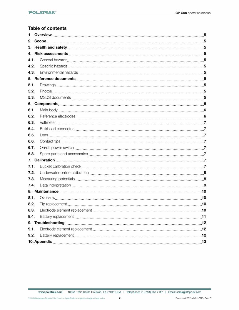
Twin referenceelectrodes verifycalibration during use
Ultra-bright LED displays for limited visibility conditions
On-off switch for season-long battery life
Interchangeable freshwater/seawater reference electrodes
CP-Gun™Diver-held probeOperation manual
www.polatrak.com | 10851 Train Court, Houston, TX 77041 USA | Telephone: +1 (713) 983 7117 | Email: [email protected]
© 2013 Deepwater Corrosion Services Inc. Specifications subject to change without notice
CP Gun operation manual
2 Document 352-MN01-ENG, Rev. D
Table of contents1 Overview 52. Scope 53. Health and safety 54. Risk assessments 54.1. General hazards 54.2. Specific hazards 54.3. Environmental hazards 55. Reference documents 55.1. Drawings 55.2. Photos 55.3. MSDS documents 56. Components 66.1. Main body 66.2. Reference electrodes 66.3. Voltmeter 76.4. Bulkhead connector 76.5. Lens 76.6. Contact tips 76.7. On/off power switch 76.8. Spare parts and accessories 77. Calibration 77.1. Bucket calibration check 77.2. Underwater online calibration 87.3. Measuring potentials 87.4. Data interpretation 98. Maintenance 108.1. Overview 108.2. Tip replacement 108.3. Electrode element replacement 108.4. Battery replacement 119. Troubleshooting 129.1. Electrode element replacement 129.2. Battery replacement 1210. Appendix 13
www.polatrak.com | 10851 Train Court, Houston, TX 77041 USA | Telephone: +1 (713) 983 7117 | Email: [email protected]
© 2013 Deepwater Corrosion Services Inc. Specifications subject to change without notice
CP Gun operation manual
3 Document 352-MN01-ENG, Rev. D
List of tablesTable 1 - Normal cathodic protection ranges for bare carbon steel in seawater 10Table 2 - Troubleshooting quick guide 13Table 3 - CP Gun spare parts list 13List of figuresFigure 1 - Kit components 4Figure 2 - Probe components 4Figure 3 - Calibration coupon attachment 8Figure 4 - Bucket calibration readings 8Figure 5 – Seacon RMG-3FS wiring diagram 11Figure 6 – Calibration schematic 14
www.polatrak.com | 10851 Train Court, Houston, TX 77041 USA | Telephone: +1 (713) 983 7117 | Email: [email protected]
© 2013 Deepwater Corrosion Services Inc. Specifications subject to change without notice
CP Gun operation manual
4 Document 352-MN01-ENG, Rev. D
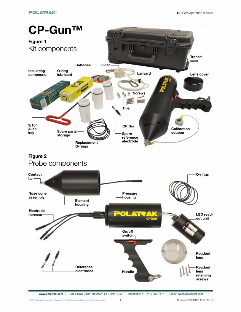
CP-Gun™Figure 1Kit components
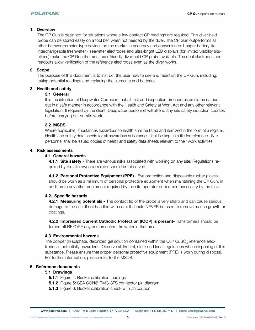
Figure 2Probe components
Pressurehousing
Reference electrodes
O-rings
LED read-out unit
Readout lens
Readout lensretaining screws
Contact tip
Nose cone assembly
Electrode harness
Element housing
On/off switch
Handle
Calibration coupon
Lens cover
Sparereference electrode
Tips
Replacement O-rings
Batteries
Screws
Float
Lanyard
Transit case
CP Gun
O-ring lubricant
Insulating compound
3/16” Allen key Spare parts
storage
www.polatrak.com | 10851 Train Court, Houston, TX 77041 USA | Telephone: +1 (713) 983 7117 | Email: [email protected]
© 2013 Deepwater Corrosion Services Inc. Specifications subject to change without notice
CP Gun operation manual
5 Document 352-MN01-ENG, Rev. D
1. OverviewThe CP Gun is designed for situations where a few contact CP readings are required. This diver-held probe can be stored easily on a tool belt when not needed by the diver. The CP Gun outperforms all other bathycorrometer-type devices on the market in accuracy and convenience. Longer battery life, interchangeable freshwater / seawater electrodes and ultra-bright LED displays (for limited visibility situ-ations) make the CP Gun the most user-friendly diver-held CP probe available. The dual electrodes and readouts allow verification of the reference electrodes even as the diver works.
2. ScopeThe purpose of this document is to instruct the user how to use and maintain the CP Gun, including: taking potential readings and replacing the elements and batteries.
3. Health and safety3.1 GeneralIt is the intention of Deepwater Corrosion that all test and inspection procedures are to be carried out in a safe manner in accordance with the Health and Safety at Work Act and any other relevant legislation. If required by the client, Deepwater personnel will attend any site safety induction courses before carrying out on-site work.
3.2 MSDSWhere applicable, substances hazardous to health shall be listed and itemized in the form of a register. Health and safety data sheets for all hazardous substances shall be kept in a file for reference. Site personnel shall be issued copies of health and safety data sheets relevant to their work activities.
4. Risk assessments4.1 General hazards
4.1.1 Site safety - There are various risks associated with working on any site; Regulations re-quired by the site owner/operator should be observed.
4.1.2 Personal Protective Equipment (PPE) - Eye protection and disposable rubber gloves should be worn as a minimum of personal protective equipment when maintaining the CP Gun, in addition to any other equipment required by the site operator or deemed necessary by the task.
4.2. Specific hazards 4.2.1 Measuring potentials - The contact tip of the probe is very sharp and can cause serious damage to the user if not handled with care. It should NEVER be used to remove marine growth or coatings.
4.2.2 Impressed Current Cathodic Protection (ICCP) is present- Transformers should be turned off BEFORE any person enters the water in that area.
4.3 Environmental hazardsThe copper (II) sulphate, deionized gel solution contained within the Cu / CuSO4 reference elec-trodes is potentially hazardous. Observe all federal, state and local regulations when disposing of this substance. Please ensure that proper personal protective equipment (PPE) is worn during disposal. For further information, please refer to the MSDS.
5. Reference documents 5.1 Drawings
5.1.1 Figure 4: Bucket calibration readings5.1.2 Figure 5: SEA CON® RMG-3FS connector pin diagram5.1.3 Figure 6: Bucket calibration check with Zn coupon
www.polatrak.com | 10851 Train Court, Houston, TX 77041 USA | Telephone: +1 (713) 983 7117 | Email: [email protected]
© 2013 Deepwater Corrosion Services Inc. Specifications subject to change without notice
CP Gun operation manual
6 Document 352-MN01-ENG, Rev. D
5.2 Photos5.2.1 Figure 1: Kit components5.2.2 Figure 2: Probe components5.2.3 Figure 3: Calibration coupon attachment
5.3 MSDS documents5.3.1 Parker Seals - Parker O Lube MSDS – O-ring lubricanthttp://www.parker.com (search for: MSDS Super O-Lube)
5.3.2 Dow Corning – 4 Electrical Insulating Compound MSDS (Connector sealant)http://www.dowcorning.com/applications/search/products/Details.aspx?prod=01903128&type=PROD
5.3.3 McMiller – Leak Stop Gel – Copper (II) sulphate electrolyte MSDShttp://documents.mcmiller.com/msds.html
Please contact your Polatrak representative for any questions and/or issues regarding this manual.
6. ComponentsThe probe components are shown in Figure 2 along with a parts list in Table 3. The CP Gun with handle weighs 6.3 lb (2.86 kg) in air and 1.5 lb (0.68 kg) in water. The following is a description of the major components:
6.1 Main bodyThe rugged thermoplastic main body of the CP Gun comprises two sections: a water-tight pressure housing which contains the LED readout unit, batteries and electronic circuitry, and a free-flooding element housing, which contains the reference electrodes, contact tip and wiring harness. These two halves are separated by unscrewing counterclockwise. This allows access to the probe contact tip connection and the reference electrodes. The tip connector attaches to the electrode harness, and once it’s unplugged, the entire electrode housing can be removed. The electrode elements and contact tip can be replaced as necessary. Please see Table 3 for part numbers and ordering information.
6.2 Reference electrodesThe CP Gun uses two replaceable silver/silver chloride (Ag/AgCl) reference electrodes. Alternatively, copper/copper sulfate (Cu/CuSO4) elements can be used for potential measurements taken in fresh water. The electrodes are plugged into the electrode harness via pressure-resistant connectors. To ensure proper function of the reference cells, several points should be observed:
6.2.1 Any time the elements are replaced, a thin layer of connector sealant should be applied to the rubber shoulder of the male end, ensuring no sealant is applied to the copper pin. Please refer to the MSDS before handling. All appropriate Personal Protective Equipment (PPE) shall be worn, including safety glasses and disposable gloves as a minimum.
6.2.2 NEVER immerse the CP Gun with any of the connectors un-mated.
6.2.3 Take care when handling reference electrode elements — NEVER get oil or grease on them.
6.2.4 NEVER touch elements with your fingers. Do not use solvent cleaners on the electrode; use only fresh water to clean.
6.2.5 After every use, soak the CP Gun in fresh water for at least 1 hour. This will extend the life of the electrodes.
www.polatrak.com | 10851 Train Court, Houston, TX 77041 USA | Telephone: +1 (713) 983 7117 | Email: [email protected]
© 2013 Deepwater Corrosion Services Inc. Specifications subject to change without notice
CP Gun operation manual
7 Document 352-MN01-ENG, Rev. D
6.3 LED readout unitEach reference electrode is connected to its own voltmeter LED readout. Both voltmeters are con-tained in a pressure housing facing the rear of the CP Gun. Power is supplied to these voltmeters by two standard, replaceable PP3 9-volt alkaline batteries. To access, see Section 8, maintenance.
6.4 Bulkhead connectorThe probe tip and reference cells are connected to the voltmeters via a Seacon 3-pin bulkhead con-nector. Before use, ensure that the connector is properly tightened. A thin layer of connector sealant should be applied to the rubber shoulder of the male end, ensuring no sealant is applied to the cop-per pin. Please refer to the MSDS before handling. All appropriate Personal Protective Equipment (PPE) shall be worn including safety glasses and disposable gloves as a minimum.
6.5 LensThe lens is made from a clear, acrylic material. The only reason to remove the lens is to replace the 9-volt batteries which power the LED readout unit.
6.6 Contact tipsTips should be replaced once a stable potential reading can no longer be obtained.Tips should not be sharpened with a file or hammered into a point. To replace, remove the existing tip with a 7/16” (or 10mm) wrench; flats are best. Ensure that the new tip is tight, but do not overtighten (max torque 50 inch-lbs).
6.7 On/off power switchThe CP Gun is powered on with the red rotational magnetic switch. With the switch in the rear (off) position, rotate the switch to the on (forward) position. If the meter does not power on, check the batteries (Section 8, maintenance). When the CP Gun is not in use, switching it off will extend the life of the batteries, enabling use of the CP Gun throughout an entire survey season without the need to replace the batteries.
CAUTIONThe contact tip has been machined to a very sharp point to enable easier readings through coatings. This point can also easily cut or poke through human skin. Please handle with care.
6.8 Spare parts and accessoriesThe CP Gun is shipped in a waterproof transit case and includes the following spares and accesso-ries. Please contact your Deepwater representative to order additional spares if required.
• Zinc calibration block (1) • Silicone connector lube (1)• Contact tip (3) • Ag/AgCl electrode element (1)• Lens retaining screw (4) • Lens back-up ring (2)• O-Ring lube (1) • Lens O-ring (4)
7. Calibration test(Please also refer to schematic in Fig. 6)
7.1 Bucket calibration check7.1.1 Fill a clean, non-metallic bucket or container with enough seawater or simulated seawater to completely submerge the probe unit. Ensure the bucket has been completely degreased and rinsed.
7.1.2 Place the probe in the bucket with the tip pointing up to fill body with seawater. The entire probe, including the tip, must be immersed. Make sure there is no trapped air in the unit.
7.1.3 With a file or sandpaper, remove any layer of oxide from the zinc coupon before placing it in the bucket.
www.polatrak.com | 10851 Train Court, Houston, TX 77041 USA | Telephone: +1 (713) 983 7117 | Email: [email protected]
© 2013 Deepwater Corrosion Services Inc. Specifications subject to change without notice
CP Gun operation manual
8 Document 352-MN01-ENG, Rev. D
7.1.4 Wait 30 minutes for the electrode elements to reach equi-librium.
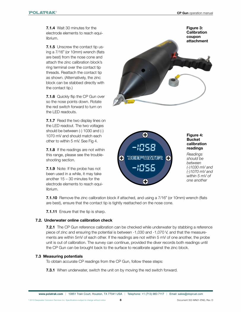
7.1.5 Unscrew the contact tip us-ing a 7/16” (or 10mm) wrench (flats are best) from the nose cone and attach the zinc calibration block’s ring terminal over the contact tip threads. Reattach the contact tip as shown. (Alternatively, the zinc block can be stabbed directly with the contact tip.)
7.1.6 Quickly flip the CP Gun over so the nose points down. Rotate the red switch forward to turn on the LED readouts.
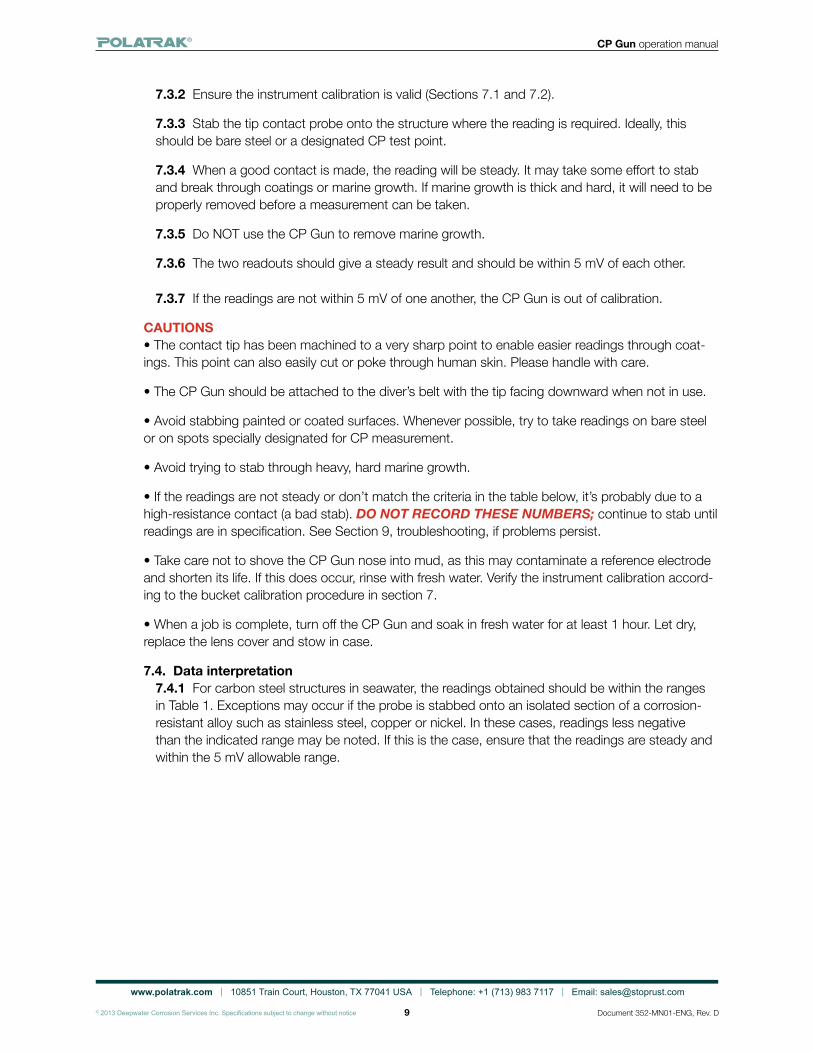
7.1.7 Read the two display lines on the LED readout. The two voltages should be between (-) 1030 and (-) 1070 mV and should match each other to within 5 mV. See Fig 4.
7.1.8 If the readings are not within this range, please see the trouble-shooting section.
7.1.9 Note: If the probe has not been used in a while, it may take another 15 – 30 minutes for the electrode elements to reach equi-librium.
7.1.10 Remove the zinc calibration block if attached, and using a 7/16” (or 10mm) wrench (flats are best), ensure that the contact tip is tightly reattached on the nose cone.
7.1.11 Ensure that the tip is sharp.
7.2. Underwater online calibration check7.2.1 The CP Gun reference calibration can be checked while underwater by stabbing a reference piece of zinc and ensuring the potential is between -1,030 and -1,070 V, and that the measure-ments are within 5mV of each other. If the readings are not within 5 mV of one another, the probe unit is out of calibration. The survey can continue, provided the diver records both readings until the CP Gun can be brought back to the surface to recalibrate against the zinc block.
7.3 Measuring potentialsTo obtain accurate CP readings from the CP Gun, follow these steps:
7.3.1 When underwater, switch the unit on by moving the red switch forward.
Figure 4:Bucket calibration readingsReadings should be between (-)1030 mV and (-)1070 mV and within 5 mV of one another
Figure 3:Calibrationcoupon attachment
www.polatrak.com | 10851 Train Court, Houston, TX 77041 USA | Telephone: +1 (713) 983 7117 | Email: [email protected]
© 2013 Deepwater Corrosion Services Inc. Specifications subject to change without notice
CP Gun operation manual
9 Document 352-MN01-ENG, Rev. D
7.3.2 Ensure the instrument calibration is valid (Sections 7.1 and 7.2).
7.3.3 Stab the tip contact probe onto the structure where the reading is required. Ideally, this should be bare steel or a designated CP test point.
7.3.4 When a good contact is made, the reading will be steady. It may take some effort to stab and break through coatings or marine growth. If marine growth is thick and hard, it will need to be properly removed before a measurement can be taken.
7.3.5 Do NOT use the CP Gun to remove marine growth.
7.3.6 The two readouts should give a steady result and should be within 5 mV of each other.
7.3.7 If the readings are not within 5 mV of one another, the CP Gun is out of calibration.
CAUTIONS• The contact tip has been machined to a very sharp point to enable easier readings through coat-ings. This point can also easily cut or poke through human skin. Please handle with care.
• The CP Gun should be attached to the diver’s belt with the tip facing downward when not in use.
• Avoid stabbing painted or coated surfaces. Whenever possible, try to take readings on bare steel or on spots specially designated for CP measurement.
• Avoid trying to stab through heavy, hard marine growth.
• If the readings are not steady or don’t match the criteria in the table below, it’s probably due to a high-resistance contact (a bad stab). DO NOT RECORD THESE NUMBERS; continue to stab until readings are in specification. See Section 9, troubleshooting, if problems persist.
• Take care not to shove the CP Gun nose into mud, as this may contaminate a reference electrode and shorten its life. If this does occur, rinse with fresh water. Verify the instrument calibration accord-ing to the bucket calibration procedure in section 7.
• When a job is complete, turn off the CP Gun and soak in fresh water for at least 1 hour. Let dry, replace the lens cover and stow in case.
7.4. Data interpretation7.4.1 For carbon steel structures in seawater, the readings obtained should be within the ranges in Table 1. Exceptions may occur if the probe is stabbed onto an isolated section of a corrosion-resistant alloy such as stainless steel, copper or nickel. In these cases, readings less negative than the indicated range may be noted. If this is the case, ensure that the readings are steady and within the 5 mV allowable range.
www.polatrak.com | 10851 Train Court, Houston, TX 77041 USA | Telephone: +1 (713) 983 7117 | Email: [email protected]
© 2013 Deepwater Corrosion Services Inc. Specifications subject to change without notice
CP Gun operation manual
10 Document 352-MN01-ENG, Rev. D
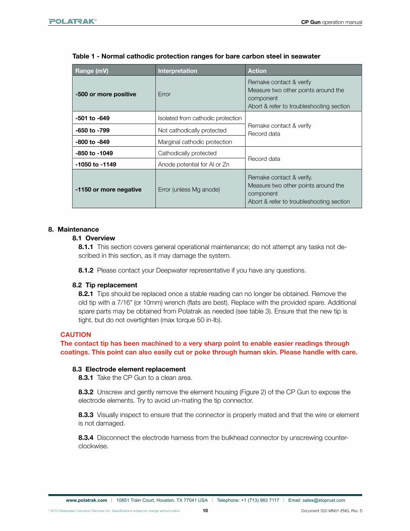
Table 1 - Normal cathodic protection ranges for bare carbon steel in seawater
Range (mV) Interpretation Action
-500 or more positive Error
Remake contact & verify Measure two other points around the component Abort & refer to troubleshooting section
-501 to -649 Isolated from cathodic protectionRemake contact & verify Record data-650 to -799 Not cathodically protected
-800 to -849 Marginal cathodic protection
-850 to -1049 Cathodically protectedRecord data
-1050 to -1149 Anode potential for Al or Zn
-1150 or more negative Error (unless Mg anode)
Remake contact & verify. Measure two other points around the component Abort & refer to troubleshooting section
8. Maintenance8.1 Overview
8.1.1 This section covers general operational maintenance; do not attempt any tasks not de-scribed in this section, as it may damage the system.
8.1.2 Please contact your Deepwater representative if you have any questions.
8.2 Tip replacement8.2.1 Tips should be replaced once a stable reading can no longer be obtained. Remove the old tip with a 7/16” (or 10mm) wrench (flats are best). Replace with the provided spare. Additional spare parts may be obtained from Polatrak as needed (see table 3). Ensure that the new tip is tight, but do not overtighten (max torque 50 in-lb).
CAUTIONThe contact tip has been machined to a very sharp point to enable easier readings through coatings. This point can also easily cut or poke through human skin. Please handle with care.
8.3 Electrode element replacement8.3.1 Take the CP Gun to a clean area.
8.3.2 Unscrew and gently remove the element housing (Figure 2) of the CP Gun to expose the electrode elements. Try to avoid un-mating the tip connector.
8.3.3 Visually inspect to ensure that the connector is properly mated and that the wire or element is not damaged.
8.3.4 Disconnect the electrode harness from the bulkhead connector by unscrewing counter-clockwise.
www.polatrak.com | 10851 Train Court, Houston, TX 77041 USA | Telephone: +1 (713) 983 7117 | Email: [email protected]
© 2013 Deepwater Corrosion Services Inc. Specifications subject to change without notice
CP Gun operation manual
11 Document 352-MN01-ENG, Rev. D
8.3.5 Repeat a bucket calibration test as described in section 7.1, but only immerse the element housing and reference electrodes. The electrode connector on the harness should remain dry.
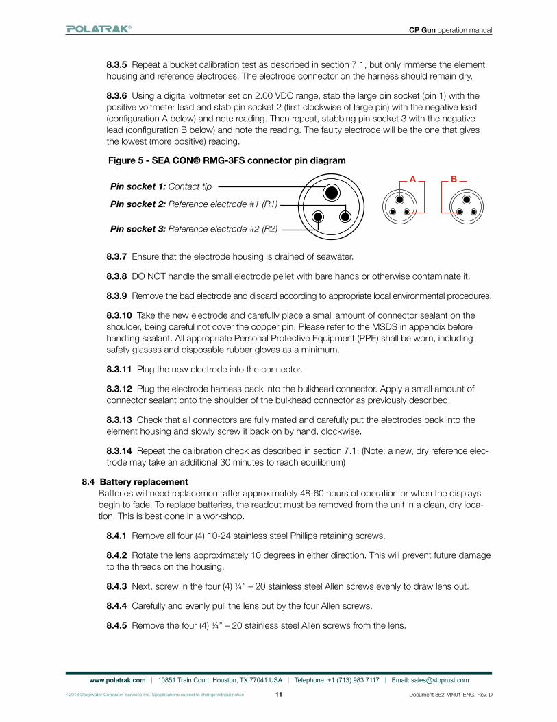
8.3.6 Using a digital voltmeter set on 2.00 VDC range, stab the large pin socket (pin 1) with the positive voltmeter lead and stab pin socket 2 (first clockwise of large pin) with the negative lead (configuration A below) and note reading. Then repeat, stabbing pin socket 3 with the negative lead (configuration B below) and note the reading. The faulty electrode will be the one that gives the lowest (more positive) reading.
Figure 5 - SEA CON® RMG-3FS connector pin diagram
8.3.7 Ensure that the electrode housing is drained of seawater.
8.3.8 DO NOT handle the small electrode pellet with bare hands or otherwise contaminate it.
8.3.9 Remove the bad electrode and discard according to appropriate local environmental procedures.
8.3.10 Take the new electrode and carefully place a small amount of connector sealant on the shoulder, being careful not cover the copper pin. Please refer to the MSDS in appendix before handling sealant. All appropriate Personal Protective Equipment (PPE) shall be worn, including safety glasses and disposable rubber gloves as a minimum.
8.3.11 Plug the new electrode into the connector.
8.3.12 Plug the electrode harness back into the bulkhead connector. Apply a small amount of connector sealant onto the shoulder of the bulkhead connector as previously described.
8.3.13 Check that all connectors are fully mated and carefully put the electrodes back into the element housing and slowly screw it back on by hand, clockwise.
8.3.14 Repeat the calibration check as described in section 7.1. (Note: a new, dry reference elec-trode may take an additional 30 minutes to reach equilibrium)
8.4 Battery replacementBatteries will need replacement after approximately 48-60 hours of operation or when the displays begin to fade. To replace batteries, the readout must be removed from the unit in a clean, dry loca-tion. This is best done in a workshop.
8.4.1 Remove all four (4) 10-24 stainless steel Phillips retaining screws.
8.4.2 Rotate the lens approximately 10 degrees in either direction. This will prevent future damage to the threads on the housing.
8.4.3 Next, screw in the four (4) ¼” – 20 stainless steel Allen screws evenly to draw lens out.
8.4.4 Carefully and evenly pull the lens out by the four Allen screws.
8.4.5 Remove the four (4) ¼” – 20 stainless steel Allen screws from the lens.
Pin socket 1: Contact tip
Pin socket 2: Reference electrode #1 (R1)
Pin socket 3: Reference electrode #2 (R2)
A B
www.polatrak.com | 10851 Train Court, Houston, TX 77041 USA | Telephone: +1 (713) 983 7117 | Email: [email protected]
© 2013 Deepwater Corrosion Services Inc. Specifications subject to change without notice
CP Gun operation manual
12 Document 352-MN01-ENG, Rev. D
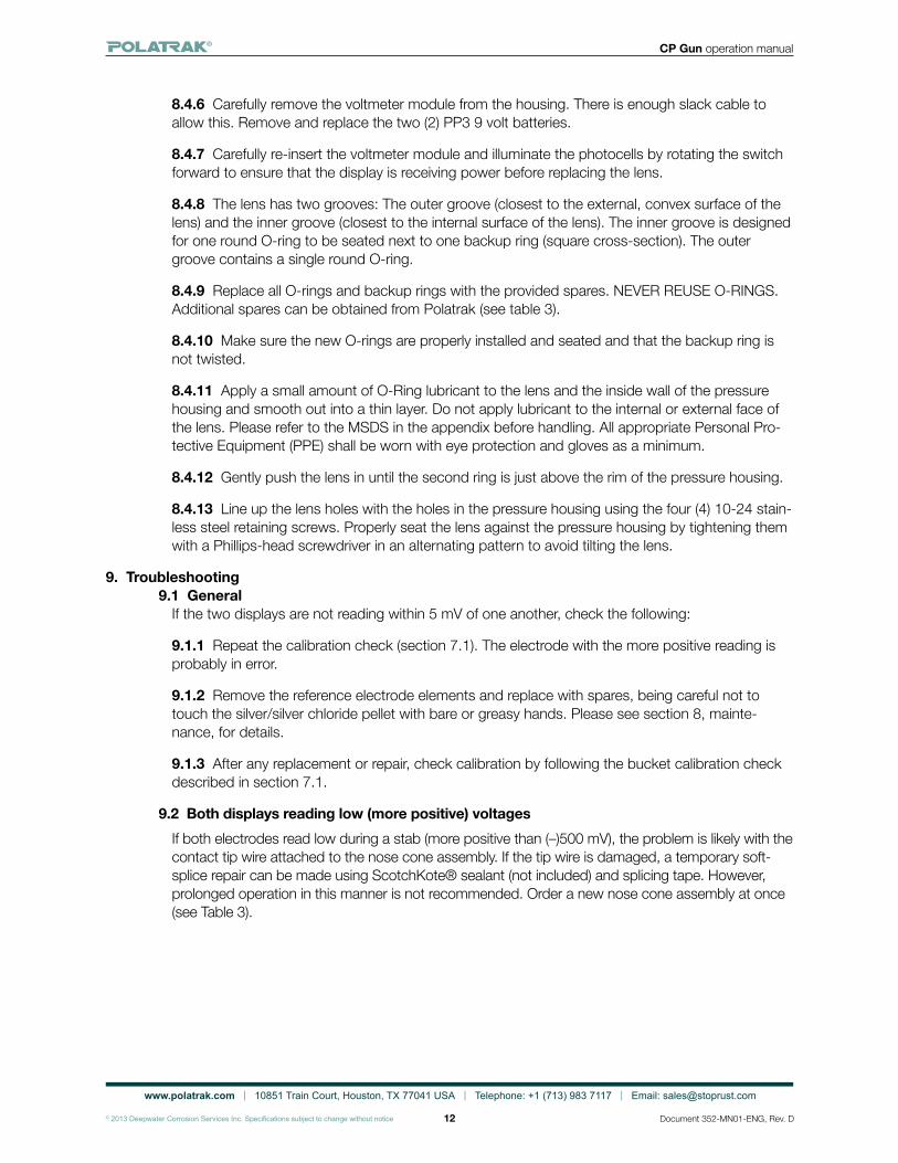
8.4.6 Carefully remove the voltmeter module from the housing. There is enough slack cable to allow this. Remove and replace the two (2) PP3 9 volt batteries.
8.4.7 Carefully re-insert the voltmeter module and illuminate the photocells by rotating the switch forward to ensure that the display is receiving power before replacing the lens.
8.4.8 The lens has two grooves: The outer groove (closest to the external, convex surface of the lens) and the inner groove (closest to the internal surface of the lens). The inner groove is designed for one round O-ring to be seated next to one backup ring (square cross-section). The outer groove contains a single round O-ring.
8.4.9 Replace all O-rings and backup rings with the provided spares. NEVER REUSE O-RINGS. Additional spares can be obtained from Polatrak (see table 3).
8.4.10 Make sure the new O-rings are properly installed and seated and that the backup ring is not twisted.
8.4.11 Apply a small amount of O-Ring lubricant to the lens and the inside wall of the pressure housing and smooth out into a thin layer. Do not apply lubricant to the internal or external face of the lens. Please refer to the MSDS in the appendix before handling. All appropriate Personal Pro-tective Equipment (PPE) shall be worn with eye protection and gloves as a minimum.
8.4.12 Gently push the lens in until the second ring is just above the rim of the pressure housing.
8.4.13 Line up the lens holes with the holes in the pressure housing using the four (4) 10-24 stain-less steel retaining screws. Properly seat the lens against the pressure housing by tightening them with a Phillips-head screwdriver in an alternating pattern to avoid tilting the lens.
9. Troubleshooting9.1 General
If the two displays are not reading within 5 mV of one another, check the following:
9.1.1 Repeat the calibration check (section 7.1). The electrode with the more positive reading is probably in error.
9.1.2 Remove the reference electrode elements and replace with spares, being careful not to touch the silver/silver chloride pellet with bare or greasy hands. Please see section 8, mainte-nance, for details.
9.1.3 After any replacement or repair, check calibration by following the bucket calibration check described in section 7.1.
9.2 Both displays reading low (more positive) voltagesIf both electrodes read low during a stab (more positive than (–)500 mV), the problem is likely with the contact tip wire attached to the nose cone assembly. If the tip wire is damaged, a temporary soft-splice repair can be made using ScotchKote® sealant (not included) and splicing tape. However, prolonged operation in this manner is not recommended. Order a new nose cone assembly at once (see Table 3).
www.polatrak.com | 10851 Train Court, Houston, TX 77041 USA | Telephone: +1 (713) 983 7117 | Email: [email protected]
© 2013 Deepwater Corrosion Services Inc. Specifications subject to change without notice
CP Gun operation manual
13 Document 352-MN01-ENG, Rev. D
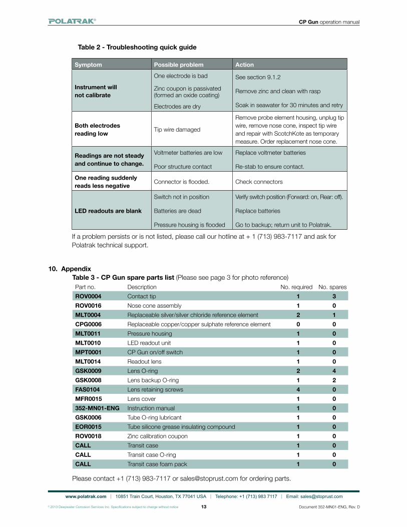
10. AppendixTable 3 ‐ CP Gun spare parts list (Please see page 3 for photo reference)Part no. Description No. required No. sparesROV0004 Contact tip 1 3ROV0016 Nose cone assembly 1 0MLT0004 Replaceable silver/silver chloride reference element 2 1CPG0006 Replaceable copper/copper sulphate reference element 0 0MLT0011 Pressure housing 1 0MLT0010 LED readout unit 1 0MPT0001 CP Gun on/off switch 1 0MLT0014 Readout lens 1 0GSK0009 Lens O-ring 2 4GSK0008 Lens backup O-ring 1 2FAS0104 Lens retaining screws 4 0MFR0015 Lens cover 1 0352‐MN01‐ENG Instruction manual 1 0GSK0006 Tube O‐ring lubricant 1 0EOR0015 Tube silicone grease insulating compound 1 0ROV0018 Zinc calibration coupon 1 0CALL Transit case 1 0CALL Transit case O‐ring 1 0CALL Transit case foam pack 1 0
Please contact +1 (713) 983‐7117 or [email protected] for ordering parts.
Table 2 - Troubleshooting quick guide
Symptom Possible problem Action
Instrument will not calibrate
One electrode is bad
Zinc coupon is passivated (formed an oxide coating)
Electrodes are dry
See section 9.1.2
Remove zinc and clean with rasp
Soak in seawater for 30 minutes and retry
Both electrodes reading low Tip wire damaged
Remove probe element housing, unplug tip wire, remove nose cone, inspect tip wire and repair with ScotchKote as temporary measure. Order replacement nose cone.
Readings are not steady and continue to change.
Voltmeter batteries are low
Poor structure contact
Replace voltmeter batteries
Re-stab to ensure contact.
One reading suddenly reads less negative Connector is flooded. Check connectors
LED readouts are blank
Switch not in position
Batteries are dead
Pressure housing is flooded
Verify switch position (Forward: on, Rear: off).
Replace batteries
Go to backup; return unit to Polatrak.
If a problem persists or is not listed, please call our hotline at + 1 (713) 983-7117 and ask for Polatrak technical support.
www.polatrak.com | 10851 Train Court, Houston, TX 77041 USA | Telephone: +1 (713) 983 7117 | Email: [email protected]
© 2013 Deepwater Corrosion Services Inc. Specifications subject to change without notice
CP Gun operation manual
14 Document 352-MN01-ENG, Rev. D
CP
GU
N
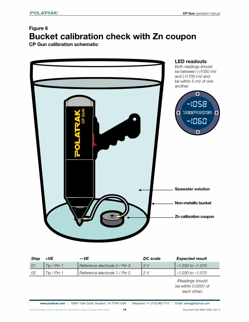
Figure 6
Bucket calibration check with Zn couponCP Gun calibration schematic
LED readoutsBoth readings should be between (-)1030 mV and (-)1700 mV and be within 5 mV of one another.
Seawater solution
Non-metallic bucket
Step +VE —VE DC scale Expected result01 Tip / Pin 1 Reference electrode 2 / Pin 3 2 V –1.030 to –1.07002 Tip / Pin 1 Reference electrode 1 / Pin 2 2 V –1.030 to –1.070
Zn calibration coupon
(Readings should be within 0.005V of
each other)