Embed Size (px)
Citation preview
0 - 1VAUXHALL CorsaVAUXHALL Corsa
Owner’s ManualModel Year 2010.5Edition: November 2009TS 1651-B-10
Introduction .................................... 2In brief ............................................ 6Keys, doors and windows ............ 18Seats, restraints ........................... 32Storage ........................................ 49Instruments and controls ............. 66Lighting ........................................ 93Infotainment system ................... 101Climate control ........................... 104Driving and operating ................. 110Vehicle care ............................... 134Service and maintenance .......... 173Technical data ........................... 177Customer information ................ 199Index .......................................... 200
Contents
2 Introduction
Introduction
Introduction 3
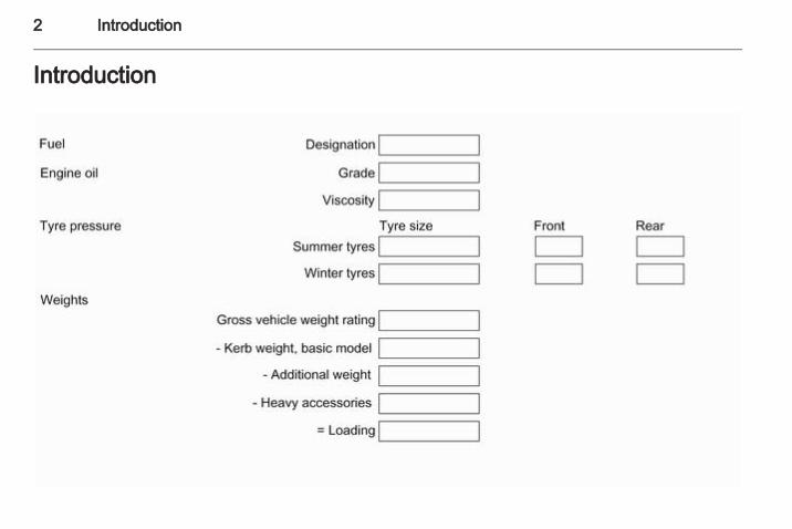
Vehicle specific dataPlease enter your vehicle's data onthe previous page to keep it easilyaccessible. This information isavailable under the sections "Serviceand Maintenance" and "Technicaldata" as well as on the identificationplate.
IntroductionYour vehicle is a designedcombination of advanced technology,safety, environmental friendlinessand economy.This Owner's Manual provides youwith all the necessary information toenable you to drive your vehiclesafely and efficiently.Make sure your passengers areaware of the possible risk of accidentand injury which may result fromimproper use of the vehicle.You must always comply with thespecific laws and regulations of thecountry that you are in. These lawsmay differ from the information in thisOwner's Manual.
When this Owner's Manual refers toa workshop visit, we recommend yourVauxhall Authorised Repairer.All Vauxhall Authorised Repairersprovide first-class service atreasonable prices. Experiencedmechanics trained by Vauxhall workaccording to specific Vauxhallinstructions.The customer literature pack shouldalways be kept ready to hand in thevehicle.
Using this manual■ This manual describes all options
and features available for thismodel. Certain descriptions,including those for display andmenu functions, may not apply toyour vehicle due to model variant,country specifications, specialequipment or accessories.
■ The "In brief" section will give youan initial overview.
■ The table of contents at thebeginning of this manual and withineach section shows where theinformation is located.
■ The index will enable you to searchfor specific information.
■ This Owner's Manual depicts left-hand drive vehicles. Operation issimilar for right-hand drive vehicles.
■ The Owner's Manual uses thefactory engine designations. Thecorresponding sales designationscan be found in the section"Technical data".
■ Directional data, e.g. left or right, orfront or back, always relate to thedirection of travel.
■ The vehicle display screens maynot support your specific language.
■ In this manual all display messagesand interior labellings are written inbold type.
4 Introduction
Danger, Warnings andCautions
9 Danger
Text marked 9 Danger providesinformation on risk of fatal injury.Disregarding this information mayendanger life.
9 Warning
Text marked 9 Warning providesinformation on risk of accident orinjury. Disregarding thisinformation may lead to injury.
Caution
Text marked Caution providesinformation on possible damage tothe vehicle. Disregarding thisinformation may lead to vehicledamage.
SymbolsPage references are indicated with3. 3 means "see page".Thank you for choosing a Vauxhall.We wish you many hours ofpleasurable driving.Your Vauxhall Team

Introduction 5
6 In brief
In brief
Initial drive information
Vehicle unlocking
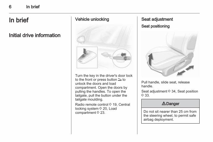
Turn the key in the driver's door lockto the front or press button q tounlock the doors and loadcompartment. Open the doors bypulling the handles. To open thetailgate, pull the button under thetailgate moulding.Radio remote control 3 19, Centrallocking system 3 20, Loadcompartment 3 23.
Seat adjustmentSeat positioning
Pull handle, slide seat, releasehandle.Seat adjustment 3 34, Seat position3 33.
9 Danger
Do not sit nearer than 25 cm fromthe steering wheel, to permit safeairbag deployment.
In brief 7
Seat backrests
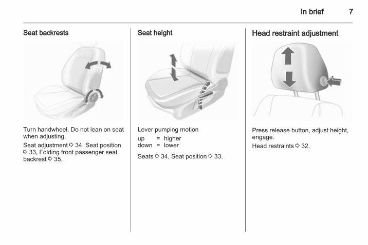
Turn handwheel. Do not lean on seatwhen adjusting.Seat adjustment 3 34, Seat position3 33, Folding front passenger seatbackrest 3 35.
Seat height
Lever pumping motionup = higherdown = lower
Seats 3 34, Seat position 3 33.
Head restraint adjustment
Press release button, adjust height,engage.Head restraints 3 32.
8 In brief
Seat belt
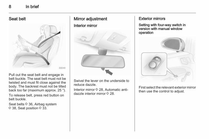
Pull out the seat belt and engage inbelt buckle. The seat belt must not betwisted and must fit close against thebody. The backrest must not be tiltedback too far (maximum approx. 25 °).To release belt, press red button onbelt buckle.Seat belts 3 36, Airbag system3 38, Seat position 3 33.
Mirror adjustmentInterior mirror
Swivel the lever on the underside toreduce dazzle.Interior mirror 3 28, Automatic anti-dazzle interior mirror 3 28.
Exterior mirrorsSetting with four-way switch inversion with manual windowoperation
First select the relevant exterior mirrorthen use the control to adjust.
In brief 9
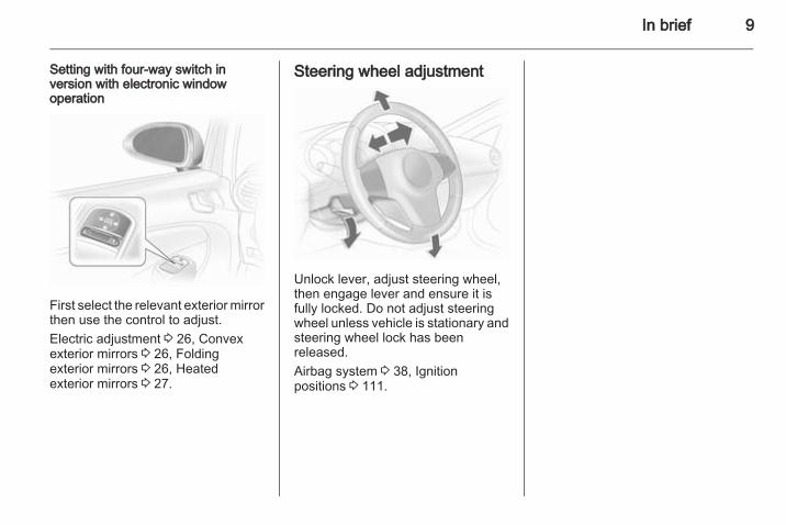
Setting with four-way switch inversion with electronic windowoperation
First select the relevant exterior mirrorthen use the control to adjust.Electric adjustment 3 26, Convexexterior mirrors 3 26, Foldingexterior mirrors 3 26, Heatedexterior mirrors 3 27.
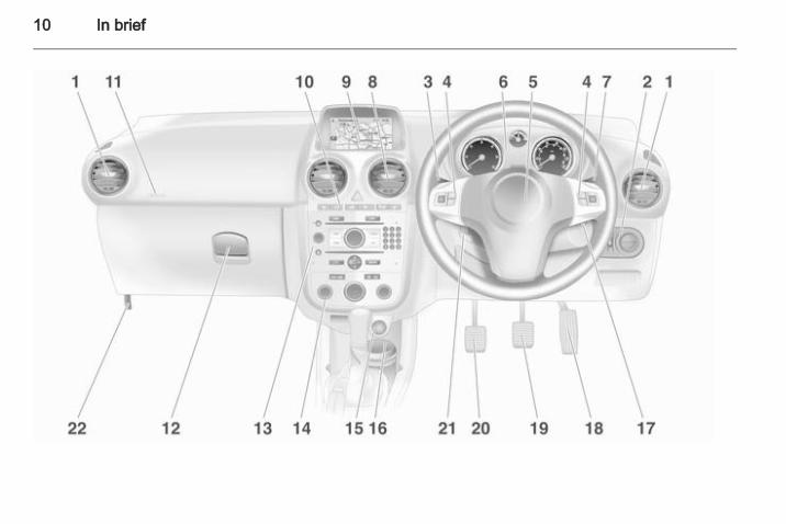
Steering wheel adjustment
Unlock lever, adjust steering wheel,then engage lever and ensure it isfully locked. Do not adjust steeringwheel unless vehicle is stationary andsteering wheel lock has beenreleased.Airbag system 3 38, Ignitionpositions 3 111.
10 In brief
In brief 11
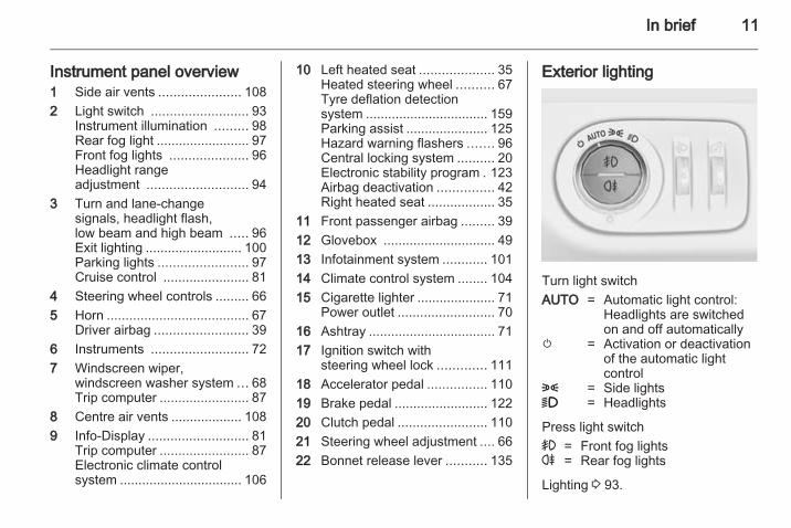
Instrument panel overview1 Side air vents ...................... 1082 Light switch .......................... 93
Instrument illumination ......... 98Rear fog light ......................... 97Front fog lights ..................... 96Headlight rangeadjustment ........................... 94
3 Turn and lane-changesignals, headlight flash,low beam and high beam ..... 96Exit lighting .......................... 100Parking lights ........................ 97Cruise control ....................... 81
4 Steering wheel controls ......... 665 Horn ...................................... 67
Driver airbag ......................... 396 Instruments .......................... 727 Windscreen wiper,
windscreen washer system ... 68Trip computer ........................ 87
8 Centre air vents ................... 1089 Info-Display ........................... 81
Trip computer ........................ 87Electronic climate controlsystem ................................. 106
10 Left heated seat .................... 35Heated steering wheel .......... 67Tyre deflation detectionsystem ................................. 159Parking assist ...................... 125Hazard warning flashers ....... 96Central locking system .......... 20Electronic stability program . 123Airbag deactivation ............... 42Right heated seat .................. 35
11 Front passenger airbag ......... 3912 Glovebox .............................. 4913 Infotainment system ............ 10114 Climate control system ........ 10415 Cigarette lighter ..................... 71
Power outlet .......................... 7016 Ashtray .................................. 7117 Ignition switch with
steering wheel lock ............. 11118 Accelerator pedal ................ 11019 Brake pedal ......................... 12220 Clutch pedal ........................ 11021 Steering wheel adjustment .... 6622 Bonnet release lever ........... 135
Exterior lighting
Turn light switchAUTO = Automatic light control:
Headlights are switchedon and off automatically
m = Activation or deactivationof the automatic lightcontrol
8 = Side lights9 = Headlights
Press light switch> = Front fog lightsr = Rear fog lights
Lighting 3 93.
12 In brief
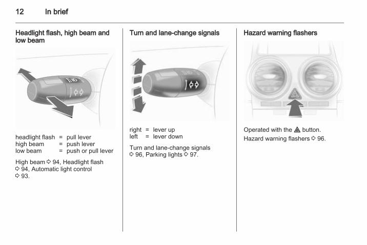
Headlight flash, high beam andlow beam
headlight flash = pull leverhigh beam = push leverlow beam = push or pull lever
High beam 3 94, Headlight flash3 94, Automatic light control3 93.
Turn and lane-change signals
right = lever upleft = lever down
Turn and lane-change signals3 96, Parking lights 3 97.
Hazard warning flashers
Operated with the ¨ button.Hazard warning flashers 3 96.
In brief 13
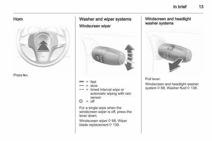
Horn
Press j.
Washer and wiper systemsWindscreen wiper
& = fast% = slow$ = timed interval wipe or
automatic wiping with rainsensor
§ = off
For a single wipe when thewindscreen wiper is off, press thelever down.Windscreen wiper 3 68, Wiperblade replacement 3 139.
Windscreen and headlightwasher systems
Pull lever.Windscreen and headlight washersystem 3 68, Washer fluid 3 138.
14 In brief
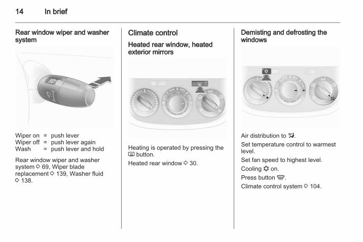
Rear window wiper and washersystem
Wiper on = push leverWiper off = push lever againWash = push lever and hold
Rear window wiper and washersystem 3 69, Wiper bladereplacement 3 139, Washer fluid3 138.
Climate controlHeated rear window, heatedexterior mirrors
Heating is operated by pressing theÜ button.Heated rear window 3 30.
Demisting and defrosting thewindows
Air distribution to l.Set temperature control to warmestlevel.Set fan speed to highest level.Cooling n on.Press button V.Climate control system 3 104.
In brief 15
TransmissionManual transmission
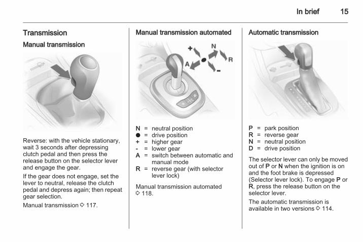
Reverse: with the vehicle stationary,wait 3 seconds after depressingclutch pedal and then press therelease button on the selector leverand engage the gear.If the gear does not engage, set thelever to neutral, release the clutchpedal and depress again; then repeatgear selection.Manual transmission 3 117.
Manual transmission automated
N = neutral positiono = drive position+ = higher gear- = lower gearA = switch between automatic and
manual modeR = reverse gear (with selector
lever lock)
Manual transmission automated3 118.
Automatic transmission
P = park positionR = reverse gearN = neutral positionD = drive position
The selector lever can only be movedout of P or N when the ignition is onand the foot brake is depressed(Selector lever lock). To engage P orR, press the release button on theselector lever.The automatic transmission isavailable in two versions 3 114.
16 In brief
Starting offCheck before starting off■ Tyre pressure and condition
3 158, 3 192.■ Engine oil level and fluid levels
3 136.■ All windows, mirrors, exterior
lighting and number plates are freefrom dirt, snow and ice and areoperational.
■ Proper position of mirrors, seats,and seat belts 3 26, 3 33,3 37.
■ Brake function at low speed,particularly if the brakes are wet.
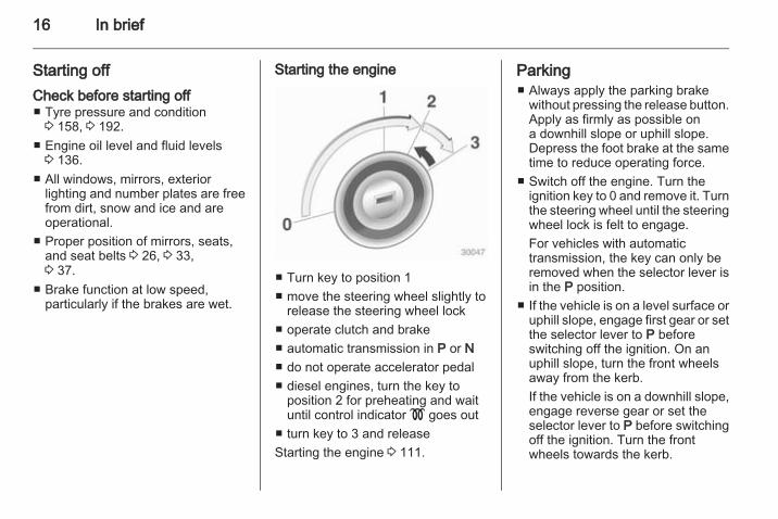
Starting the engine
■ Turn key to position 1■ move the steering wheel slightly to
release the steering wheel lock■ operate clutch and brake■ automatic transmission in P or N■ do not operate accelerator pedal■ diesel engines, turn the key to
position 2 for preheating and waituntil control indicator ! goes out
■ turn key to 3 and releaseStarting the engine 3 111.
Parking■ Always apply the parking brake
without pressing the release button.Apply as firmly as possible ona downhill slope or uphill slope.Depress the foot brake at the sametime to reduce operating force.
■ Switch off the engine. Turn theignition key to 0 and remove it. Turnthe steering wheel until the steeringwheel lock is felt to engage.For vehicles with automatictransmission, the key can only beremoved when the selector lever isin the P position.
■ If the vehicle is on a level surface oruphill slope, engage first gear or setthe selector lever to P beforeswitching off the ignition. On anuphill slope, turn the front wheelsaway from the kerb.If the vehicle is on a downhill slope,engage reverse gear or set theselector lever to P before switchingoff the ignition. Turn the frontwheels towards the kerb.
In brief 17
■ Lock the vehicle with button p onthe radio remote control.Activate the anti-theft alarm system3 24.
■ Do not park the vehicle on an easilyignitable surface. The hightemperature of the exhaust systemcould ignite the surface.
■ Close windows and sunroof.■ The engine cooling fans may run
after the engine has been switchedoff 3 135.
■ After running at high engine speedsor with high engine loads, operatethe engine briefly at a low load orrun in neutral for approx. 30seconds before switching off, inorder to protect the turbocharger.
Keys, locks 3 18,Laying the vehicle up for a long periodof time 3 134.
18 Keys, doors and windows
Keys, doors andwindows
Keys, locks ................................... 18Doors ........................................... 23Vehicle security ............................ 24Exterior mirrors ............................ 26Interior mirrors ............................. 28Windows ...................................... 28Roof ............................................. 30
Keys, locksKeysReplacement keysThe key number is specified in theCar Pass or on a detachable tag.The key number must be quotedwhen ordering replacement keys as itis a component of the immobilisersystem.Locks 3 170
Lock cylindersDesigned to free-wheel if they areforcefully rotated without the correctkey or if the correct key is not fullyinserted. To reset, turn cylinder withthe correct key until its slot is vertical,remove key and then re-insert it. If thecylinder still free-wheels, turn the keythrough 180° and repeat operation.
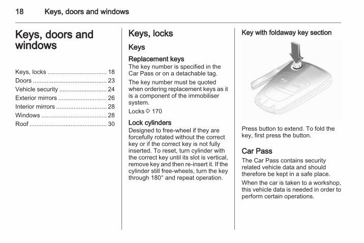
Key with foldaway key section
Press button to extend. To fold thekey, first press the button.
Car PassThe Car Pass contains securityrelated vehicle data and shouldtherefore be kept in a safe place.When the car is taken to a workshop,this vehicle data is needed in order toperform certain operations.
Keys, doors and windows 19
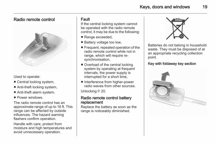
Radio remote control
Used to operate:■ Central locking system,■ Anti-theft locking system,■ Anti-theft alarm system,■ Power windows.The radio remote control has anapproximate range of up to 16 ft. Thisrange can be affected by outsideinfluences. The hazard warningflashers confirm operation.Handle with care, protect frommoisture and high temperatures andavoid unnecessary operation.
FaultIf the central locking system cannotbe operated with the radio remotecontrol, it may be due to the following:■ Range exceeded,■ Battery voltage too low,■ Frequent, repeated operation of the
radio remote control while not inrange, which will require re-synchronisation,
■ Overload of the central lockingsystem by operating at frequentintervals, the power supply isinterrupted for a short time,
■ Interference from higher-powerradio waves from other sources.
Unlocking 3 20.
Radio remote control batteryreplacementReplace the battery as soon as therange is noticeably diminished.
Batteries do not belong in householdwaste. They must be disposed of atan appropriate recycling collectionpoint.
Key with foldaway key section
20 Keys, doors and windows
Extend the key and open the unit.Replace the battery (battery typeCR 2032), paying attention to theinstallation position. Close the unitand synchronise.
Key with fixed key sectionHave the battery replaced bya workshop.
Radio remote controlsynchronisationAfter replacing the battery, unlock thedoor with the key in the driver's doorlock. The radio remote control will besynchronised when you switch on theignition.
Memorised settingsWhenever the vehicle is locked, thefollowing settings are automaticallymemorised by the key being used:■ Electronic climate control,■ Info-Display,■ Infotainment system,■ Instrument panel illumination.
The saved settings are automaticallyused next time that key is used forunlocking.
Central locking systemUnlocks and locks doors, loadcompartment and fuel filler flap.A pull on an interior door handleunlocks the entire vehicle and opensthe door.NoteIn the event of an accident ofa certain severity, the vehicleunlocks automatically.NoteA short time after unlocking with theremote control the doors are lockedautomatically if no door has beenopened.
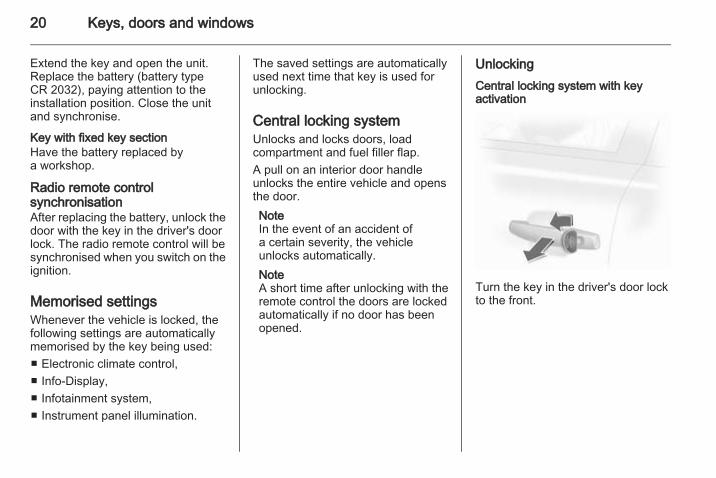
UnlockingCentral locking system with keyactivation
Turn the key in the driver's door lockto the front.
Keys, doors and windows 21
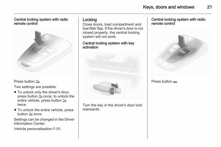
Central locking system with radioremote control
Press button q.Two settings are possible:■ To unlock only the driver's door,
press button q once, to unlock theentire vehicle, press button qtwice.
■ To unlock the entire vehicle, pressbutton q once.
Settings can be changed in the DriverInformation Center.Vehicle personalisation 3 91.
LockingClose doors, load compartment andfuel filler flap. If the driver's door is notclosed properly, the central lockingsystem will not work.
Central locking system with keyactivation
Turn the key in the driver's door lockrearwards.
Central locking system with radioremote control
Press button p.
22 Keys, doors and windows
Central locking button
Press button m: the doors are lockedor unlocked.The LED in the button m illuminatesfor approx. 2 minutes after lockingwith the radio remote control.If the doors are locked from the insidewhilst driving, the LED remains lit.
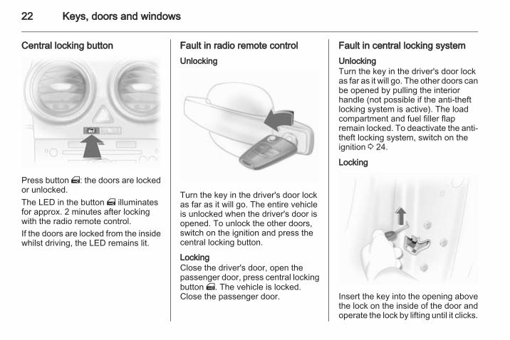
Fault in radio remote controlUnlocking
Turn the key in the driver's door lockas far as it will go. The entire vehicleis unlocked when the driver's door isopened. To unlock the other doors,switch on the ignition and press thecentral locking button.
LockingClose the driver's door, open thepassenger door, press central lockingbutton m. The vehicle is locked.Close the passenger door.
Fault in central locking systemUnlockingTurn the key in the driver's door lockas far as it will go. The other doors canbe opened by pulling the interiorhandle (not possible if the anti-theftlocking system is active). The loadcompartment and fuel filler flapremain locked. To deactivate the anti-theft locking system, switch on theignition 3 24.
Locking
Insert the key into the opening abovethe lock on the inside of the door andoperate the lock by lifting until it clicks.
Keys, doors and windows 23
Then close the door. The proceduremust be carried out for each door. Thedriver's door can also be locked fromthe outside with the key. The fuel fillerflap and tailgate cannot be locked.
Automatic lockingThis security feature can beconfigured to automatically lock alldoors, load compartment and fuelfiller flap as soon as the vehicle isdriven. Vehicle personalisation3 91.
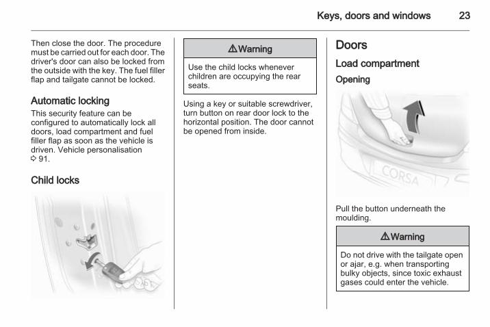
Child locks
9 Warning
Use the child locks wheneverchildren are occupying the rearseats.
Using a key or suitable screwdriver,turn button on rear door lock to thehorizontal position. The door cannotbe opened from inside.
DoorsLoad compartmentOpening
Pull the button underneath themoulding.
9 Warning
Do not drive with the tailgate openor ajar, e.g. when transportingbulky objects, since toxic exhaustgases could enter the vehicle.
24 Keys, doors and windows
NoteThe installation of certain heavyaccessories onto the tailgate mayaffect its ability to remain open.
Closing
Use the interior handle.Do not press the button under themoulding while closing as this willunlock the tailgate again.
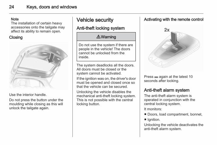
Vehicle securityAnti-theft locking system
9 Warning
Do not use the system if there arepeople in the vehicle! The doorscannot be unlocked from theinside.
The system deadlocks all the doors.All doors must be closed or thesystem cannot be activated.If the ignition was on, the driver's doormust be opened and closed once sothat the vehicle can be secured.Unlocking the vehicle disables themechanical anti-theft locking system.This is not possible with the centrallocking button.
Activating with the remote control
Press p again at the latest 10seconds after locking.
Anti-theft alarm systemThe anti-theft alarm system isoperated in conjunction with thecentral locking system.It monitors:■ Doors, load compartment, bonnet,■ Ignition.Unlocking the vehicle deactivates theanti-theft alarm system.
Keys, doors and windows 25
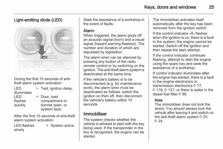
Light-emitting diode (LED)
During the first 10 seconds of anti-theft alarm system activation:LEDilluminates
= Test, ignition delay,
LEDflashesquickly
= Door, loadcompartment orbonnet open, orsystem fault.
After the first 10 seconds of anti-theftalarm system activation:LED flashesslowly
= System active.
Seek the assistance of a workshop inthe event of faults.
AlarmWhen triggered, the alarm gives offan acoustic signal (horn) and a visualsignal (hazard warning flashers). Thenumber and duration of which arestipulated by legislation.The alarm siren can be silenced bypressing any button of the radioremote control or by switching on theignition. The anti-theft alarm system isdeactivated at the same time.If the vehicle's battery is to bedisconnected (e.g. for maintenancework), the alarm siren must bedeactivated as follows: switch theignition on then off, then disconnectthe vehicle's battery within 15seconds.
ImmobiliserThe system checks whether thevehicle is allowed to start with the keybeing used. If the transponder in thekey is recognised, the engine can bestarted.
The immobiliser activates itselfautomatically after the key has beenremoved from the ignition switch.If the control indicator A flasheswhen the ignition is on, there is a faultin the system; the engine cannot bestarted. Switch off the ignition andthen repeat the start attempt.If the control indicator continuesflashing, attempt to start the engineusing the spare key and seek theassistance of a workshop.If control indicator illuminates afterthe engine has started, there is a faultin the engine electronics ortransmission electronics 3 77,3 116, 3 121, or there is water in thediesel fuel filter 3 86.NoteThe immobiliser does not lock thedoors. You should always lock thevehicle after leaving it and switch onthe anti-theft alarm system 3 20,3 24.
26 Keys, doors and windows
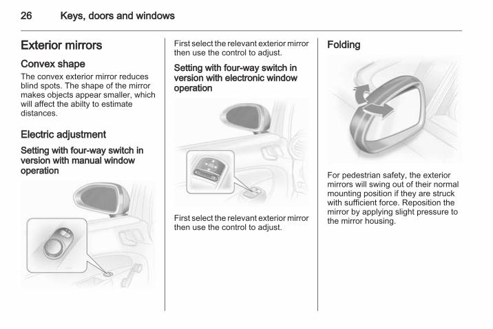
Exterior mirrorsConvex shapeThe convex exterior mirror reducesblind spots. The shape of the mirrormakes objects appear smaller, whichwill affect the abilty to estimatedistances.
Electric adjustmentSetting with four-way switch inversion with manual windowoperation
First select the relevant exterior mirrorthen use the control to adjust.
Setting with four-way switch inversion with electronic windowoperation
First select the relevant exterior mirrorthen use the control to adjust.
Folding
For pedestrian safety, the exteriormirrors will swing out of their normalmounting position if they are struckwith sufficient force. Reposition themirror by applying slight pressure tothe mirror housing.
Keys, doors and windows 27
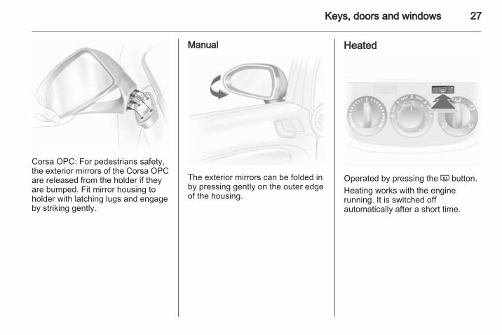
Corsa OPC: For pedestrians safety,the exterior mirrors of the Corsa OPCare released from the holder if theyare bumped. Fit mirror housing toholder with latching lugs and engageby striking gently.
Manual
The exterior mirrors can be folded inby pressing gently on the outer edgeof the housing.
Heated
Operated by pressing the Ü button.Heating works with the enginerunning. It is switched offautomatically after a short time.
28 Keys, doors and windows
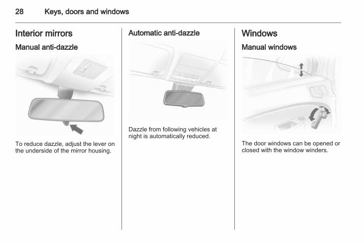
Interior mirrorsManual anti-dazzle
To reduce dazzle, adjust the lever onthe underside of the mirror housing.
Automatic anti-dazzle
Dazzle from following vehicles atnight is automatically reduced.
WindowsManual windows
The door windows can be opened orclosed with the window winders.
Keys, doors and windows 29
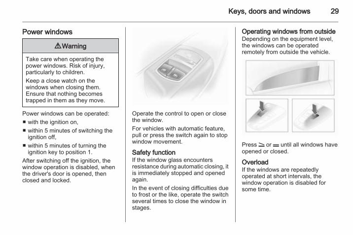
Power windows
9 Warning
Take care when operating thepower windows. Risk of injury,particularly to children.Keep a close watch on thewindows when closing them.Ensure that nothing becomestrapped in them as they move.
Power windows can be operated:■ with the ignition on,■ within 5 minutes of switching the
ignition off,■ within 5 minutes of turning the
ignition key to position 1.After switching off the ignition, thewindow operation is disabled, whenthe driver's door is opened, thenclosed and locked.
Operate the control to open or closethe window.For vehicles with automatic feature,pull or press the switch again to stopwindow movement.
Safety functionIf the window glass encountersresistance during automatic closing, itis immediately stopped and openedagain.In the event of closing difficulties dueto frost or the like, operate the switchseveral times to close the window instages.
Operating windows from outsideDepending on the equipment level,the windows can be operatedremotely from outside the vehicle.
Press q or p until all windows haveopened or closed.
OverloadIf the windows are repeatedlyoperated at short intervals, thewindow operation is disabled forsome time.
30 Keys, doors and windows
FaultIf the windows cannot be opened orclosed automatically, activate thewindow electronics as follows:1. Close doors.2. Switch on ignition.3. Close the window completely and
operate the button for 5 moreseconds.
4. Open the window completely andoperate the button for 1 moresecond.
5. Repeat this for each window.
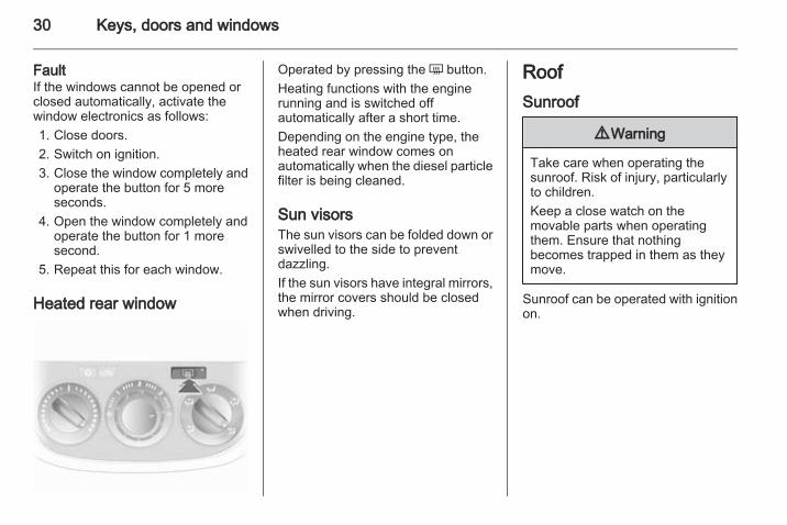
Heated rear window
Operated by pressing the Ü button.Heating functions with the enginerunning and is switched offautomatically after a short time.Depending on the engine type, theheated rear window comes onautomatically when the diesel particlefilter is being cleaned.
Sun visorsThe sun visors can be folded down orswivelled to the side to preventdazzling.If the sun visors have integral mirrors,the mirror covers should be closedwhen driving.
RoofSunroof
9 Warning
Take care when operating thesunroof. Risk of injury, particularlyto children.Keep a close watch on themovable parts when operatingthem. Ensure that nothingbecomes trapped in them as theymove.
Sunroof can be operated with ignitionon.
Keys, doors and windows 31
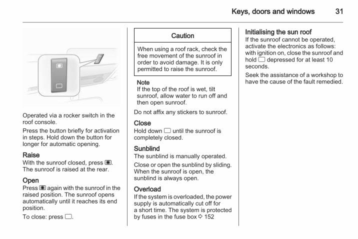
Operated via a rocker switch in theroof console.Press the button briefly for activationin steps. Hold down the button forlonger for automatic opening.
RaiseWith the sunroof closed, press ü.The sunroof is raised at the rear.
OpenPress ü again with the sunroof in theraised position. The sunroof opensautomatically until it reaches its endposition.To close: press d.
Caution
When using a roof rack, check thefree movement of the sunroof inorder to avoid damage. It is onlypermitted to raise the sunroof.
NoteIf the top of the roof is wet, tiltsunroof, allow water to run off andthen open sunroof.
Do not affix any stickers to sunroof.
CloseHold down d until the sunroof iscompletely closed.
SunblindThe sunblind is manually operated.Close or open the sunblind by sliding.When the sunroof is open, thesunblind is always open.
OverloadIf the system is overloaded, the powersupply is automatically cut off fora short time. The system is protectedby fuses in the fuse box 3 152
Initialising the sun roofIf the sunroof cannot be operated,activate the electronics as follows:with ignition on, close the sunroof andhold d depressed for at least 10seconds.Seek the assistance of a workshop tohave the cause of the fault remedied.
32 Seats, restraints
Seats, restraints
Head restraints ............................ 32Front seats ................................... 33Seat belts ..................................... 36Airbag system .............................. 38Child restraints ............................. 43
Head restraints
Position
9 Warning
Only drive with the head restraintset to the proper position.
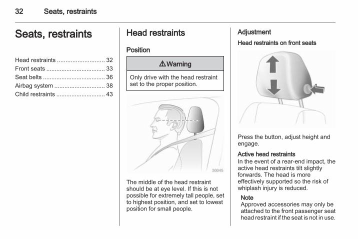
The middle of the head restraintshould be at eye level. If this is notpossible for extremely tall people, setto highest position, and set to lowestposition for small people.
AdjustmentHead restraints on front seats
Press the button, adjust height andengage.
Active head restraintsIn the event of a rear-end impact, theactive head restraints tilt slightlyforwards. The head is moreeffectively supported so the risk ofwhiplash injury is reduced.NoteApproved accessories may only beattached to the front passenger seathead restraint if the seat is not in use.
Seats, restraints 33
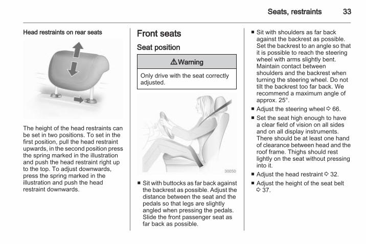
Head restraints on rear seats
The height of the head restraints canbe set in two positions. To set in thefirst position, pull the head restraintupwards, in the second position pressthe spring marked in the illustrationand push the head restraint right upto the top. To adjust downwards,press the spring marked in theillustration and push the headrestraint downwards.
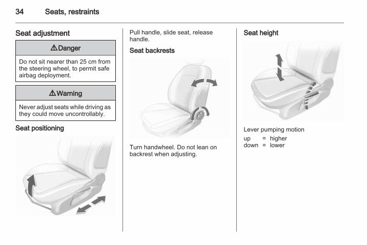
Front seatsSeat position
9 Warning
Only drive with the seat correctlyadjusted.
■ Sit with buttocks as far back againstthe backrest as possible. Adjust thedistance between the seat and thepedals so that legs are slightlyangled when pressing the pedals.Slide the front passenger seat asfar back as possible.
■ Sit with shoulders as far backagainst the backrest as possible.Set the backrest to an angle so thatit is possible to reach the steeringwheel with arms slightly bent.Maintain contact betweenshoulders and the backrest whenturning the steering wheel. Do nottilt the backrest too far back. Werecommend a maximum angle ofapprox. 25°.
■ Adjust the steering wheel 3 66.■ Set the seat high enough to have
a clear field of vision on all sidesand on all display instruments.There should be at least one handof clearance between head and theroof frame. Thighs should restlightly on the seat without pressinginto it.
■ Adjust the head restraint 3 32.■ Adjust the height of the seat belt
3 37.
34 Seats, restraints
Seat adjustment
9 Danger
Do not sit nearer than 25 cm fromthe steering wheel, to permit safeairbag deployment.
9 Warning
Never adjust seats while driving asthey could move uncontrollably.
Seat positioning
Pull handle, slide seat, releasehandle.
Seat backrests
Turn handwheel. Do not lean onbackrest when adjusting.
Seat height
Lever pumping motionup = higherdown = lower
Seats, restraints 35
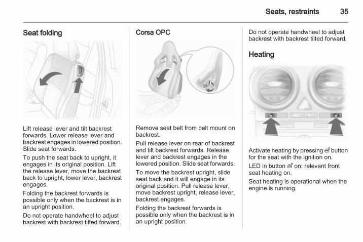
Seat folding
Lift release lever and tilt backrestforwards. Lower release lever andbackrest engages in lowered position.Slide seat forwards.To push the seat back to upright, itengages in its original position. Liftthe release lever, move the backrestback to upright, lower lever, backrestengages.Folding the backrest forwards ispossible only when the backrest is inan upright position.Do not operate handwheel to adjustbackrest with backrest tilted forward.
Corsa OPC
Remove seat belt from belt mount onbackrest.Pull release lever on rear of backrestand tilt backrest forwards. Releaselever and backrest engages in thelowered position. Slide seat forwards.To move the backrest upright, slideseat back and it will engage in itsoriginal position. Pull release lever,move backrest upright, release lever,backrest engages.Folding the backrest forwards ispossible only when the backrest is inan upright position.
Do not operate handwheel to adjustbackrest with backrest tilted forward.
Heating
Activate heating by pressing ß buttonfor the seat with the ignition on.LED in button ß on: relevant frontseat heating on.Seat heating is operational when theengine is running.
36 Seats, restraints
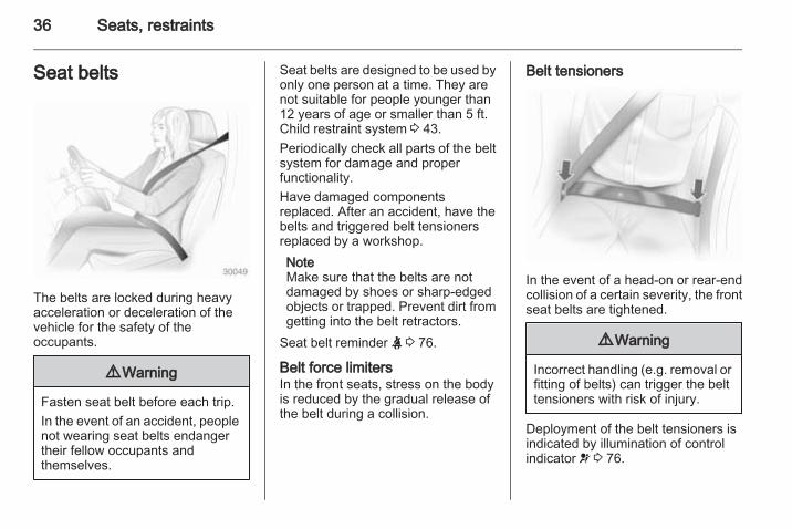
Seat belts
The belts are locked during heavyacceleration or deceleration of thevehicle for the safety of theoccupants.
9 Warning
Fasten seat belt before each trip.In the event of an accident, peoplenot wearing seat belts endangertheir fellow occupants andthemselves.
Seat belts are designed to be used byonly one person at a time. They arenot suitable for people younger than12 years of age or smaller than 5 ft.Child restraint system 3 43.Periodically check all parts of the beltsystem for damage and properfunctionality.Have damaged componentsreplaced. After an accident, have thebelts and triggered belt tensionersreplaced by a workshop.NoteMake sure that the belts are notdamaged by shoes or sharp-edgedobjects or trapped. Prevent dirt fromgetting into the belt retractors.
Seat belt reminder X 3 76.
Belt force limitersIn the front seats, stress on the bodyis reduced by the gradual release ofthe belt during a collision.
Belt tensioners
In the event of a head-on or rear-endcollision of a certain severity, the frontseat belts are tightened.
9 Warning
Incorrect handling (e.g. removal orfitting of belts) can trigger the belttensioners with risk of injury.
Deployment of the belt tensioners isindicated by illumination of controlindicator v 3 76.
Seats, restraints 37
Triggered belt tensioners must bereplaced by a workshop. Belttensioners can only be triggeredonce.NoteDo not affix or install accessories orother objects that may interfere withthe operation of the belt tensioners.Do not make any modifications tobelt tensioner components as thiswill invalidate the vehicle typeapproval.
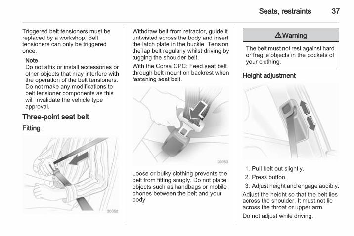
Three-point seat beltFitting
Withdraw belt from retractor, guide ituntwisted across the body and insertthe latch plate in the buckle. Tensionthe lap belt regularly whilst driving bytugging the shoulder belt.With the Corsa OPC: Feed seat beltthrough belt mount on backrest whenfastening seat belt.
Loose or bulky clothing prevents thebelt from fitting snugly. Do not placeobjects such as handbags or mobilephones between the belt and yourbody.
9 Warning
The belt must not rest against hardor fragile objects in the pockets ofyour clothing.
Height adjustment
1. Pull belt out slightly.2. Press button.3. Adjust height and engage audibly.
Adjust the height so that the belt liesacross the shoulder. It must not lieacross the throat or upper arm.Do not adjust while driving.
38 Seats, restraints
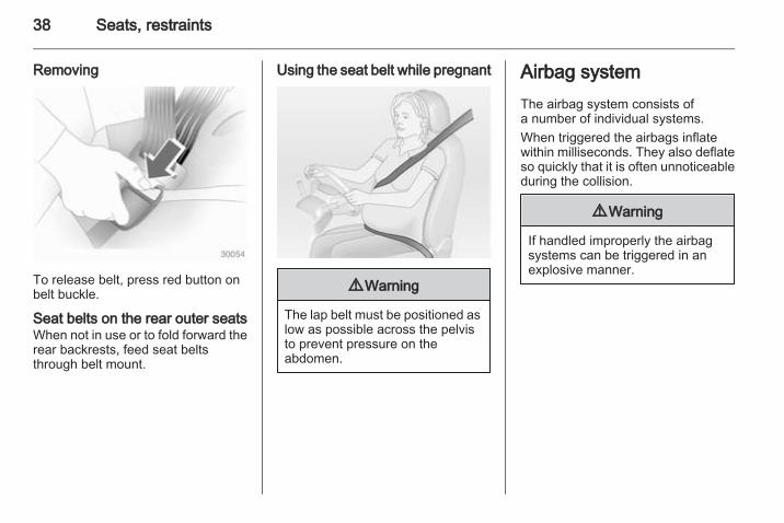
Removing
To release belt, press red button onbelt buckle.
Seat belts on the rear outer seatsWhen not in use or to fold forward therear backrests, feed seat beltsthrough belt mount.
Using the seat belt while pregnant
9 Warning
The lap belt must be positioned aslow as possible across the pelvisto prevent pressure on theabdomen.
Airbag systemThe airbag system consists ofa number of individual systems.When triggered the airbags inflatewithin milliseconds. They also deflateso quickly that it is often unnoticeableduring the collision.
9 Warning
If handled improperly the airbagsystems can be triggered in anexplosive manner.
Seats, restraints 39
NoteThe airbag systems and beltpretensioner control electronics arelocated in the centre console area.Do not put any magnetic objects inthis area.Do not stick anything on the airbagcovers and do not cover them withother materials.Each airbag is triggered only once.Have deployed airbags replaced bya workshop. Furthermore, it might benecessary to have the steeringwheel, the instrument panel, parts ofthe panelling, the door seals,handles and the seats replaced.Do not make any modifications tothe airbag system as this willinvalidate the vehicle type approval.
When the airbags inflate, escapinghot gases may cause burns.Control indicator v for airbag systems3 76.
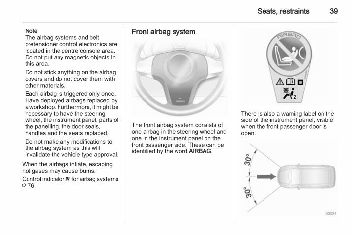
Front airbag system
The front airbag system consists ofone airbag in the steering wheel andone in the instrument panel on thefront passenger side. These can beidentified by the word AIRBAG.
There is also a warning label on theside of the instrument panel, visiblewhen the front passenger door isopen.
40 Seats, restraints
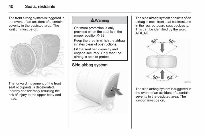
The front airbag system is triggered inthe event of an accident of a certainseverity in the depicted area. Theignition must be on.
The forward movement of the frontseat occupants is decelerated,thereby considerably reducing therisk of injury to the upper body andhead.
9 Warning
Optimum protection is onlyprovided when the seat is in theproper position 3 33.Keep the area in which the airbaginflates clear of obstructions.Fit the seat belt correctly andengage securely. Only then theairbag is able to protect.
Side airbag system
The side airbag system consists of anairbag in each front seat backrest andin the rear outboard seat backrests.This can be identified by the wordAIRBAG.
The side airbag system is triggered inthe event of an accident of a certainseverity in the depicted area. Theignition must be on.
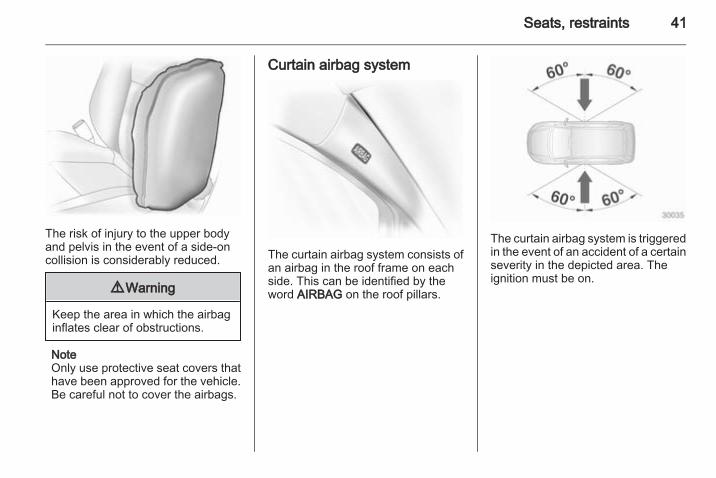
Seats, restraints 41
The risk of injury to the upper bodyand pelvis in the event of a side-oncollision is considerably reduced.
9 Warning
Keep the area in which the airbaginflates clear of obstructions.
NoteOnly use protective seat covers thathave been approved for the vehicle.Be careful not to cover the airbags.
Curtain airbag system
The curtain airbag system consists ofan airbag in the roof frame on eachside. This can be identified by theword AIRBAG on the roof pillars.
The curtain airbag system is triggeredin the event of an accident of a certainseverity in the depicted area. Theignition must be on.
42 Seats, restraints
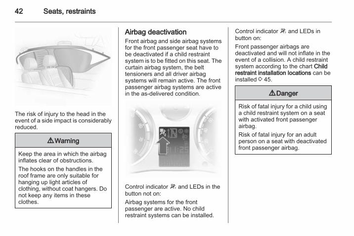
The risk of injury to the head in theevent of a side impact is considerablyreduced.
9 Warning
Keep the area in which the airbaginflates clear of obstructions.The hooks on the handles in theroof frame are only suitable forhanging up light articles ofclothing, without coat hangers. Donot keep any items in theseclothes.
Airbag deactivationFront airbag and side airbag systemsfor the front passenger seat have tobe deactivated if a child restraintsystem is to be fitted on this seat. Thecurtain airbag system, the belttensioners and all driver airbagsystems will remain active. The frontpassenger airbag systems are activein the as-delivered condition.
Control indicator W and LEDs in thebutton not on:Airbag systems for the frontpassenger are active. No childrestraint systems can be installed.
Control indicator W and LEDs inbutton on:Front passenger airbags aredeactivated and will not inflate in theevent of a collision. A child restraintsystem according to the chart Childrestraint installation locations can beinstalled 3 45.
9 Danger
Risk of fatal injury for a child usinga child restraint system on a seatwith activated front passengerairbag.Risk of fatal injury for an adultperson on a seat with deactivatedfront passenger airbag.
Seats, restraints 43
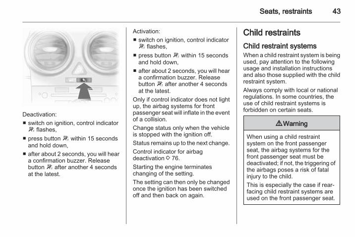
Deactivation:■ switch on ignition, control indicatorW flashes,
■ press button W within 15 secondsand hold down,
■ after about 2 seconds, you will heara confirmation buzzer. Releasebutton W after another 4 secondsat the latest.
Activation:■ switch on ignition, control indicatorW flashes,
■ press button W within 15 secondsand hold down,
■ after about 2 seconds, you will heara confirmation buzzer. Releasebutton W after another 4 secondsat the latest.
Only if control indicator does not lightup, the airbag systems for frontpassenger seat will inflate in the eventof a collision.Change status only when the vehicleis stopped with the ignition off.Status remains up to the next change.Control indicator for airbagdeactivation 3 76.Starting the engine terminateschanging of the setting.The setting can then only be changedonce the ignition has been switchedoff and then back on again.
Child restraintsChild restraint systemsWhen a child restraint system is beingused, pay attention to the followingusage and installation instructionsand also those supplied with the childrestraint system.Always comply with local or nationalregulations. In some countries, theuse of child restraint systems isforbidden on certain seats.
9 Warning
When using a child restraintsystem on the front passengerseat, the airbag systems for thefront passenger seat must bedeactivated; if not, the triggering ofthe airbags poses a risk of fatalinjury to the child.This is especially the case if rear-facing child restraint systems areused on the front passenger seat.
44 Seats, restraints
Selecting the right systemChildren should travel facingrearwards in the vehicle as long aspossible. This makes sure that thechild's backbone, which is still veryweak, is under less strain in the eventof an accident.Children under the age of 12 yearsthat are smaller than 5 ft are onlyallowed to travel in a restraint systemthat is suitable for the child. Suitableare restraint systems that comply withECE 44-03 or ECE 44-04. Sincea proper position of the belt is rarelypossible with a child that is smallerthan 5 ft, we strongly advise to use anappropriate child restraint system,even though this might, due to the ageof the child, no longer be legallybinding.Never hold a child whilst travelling inthe vehicle. The child will become tooheavy to be held in the event ofa collision.When transporting children, use thechild restraint systems suitable for thechild's weight.
Ensure that the child restraint systemto be installed is compatible with thevehicle type.Ensure that the mounting location ofthe child restraint system within thevehicle is correct.Only allow children to enter and exitthe vehicle at the side facing awayfrom the traffic.When the child restraint system is notin use, secure the seat with a seat beltor remove it from the vehicle.NoteDo not stick anything on the childrestraint systems and do not coverthem with any other materials.A child restraint system which hasbeen subjected to stress in anaccident must be replaced.
Seats, restraints 45
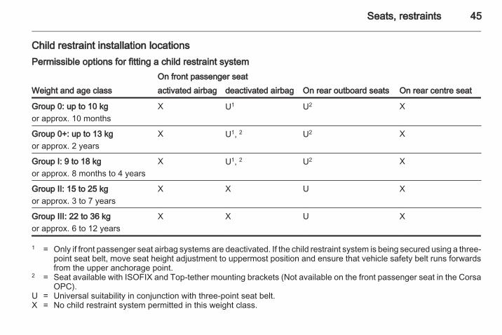
Child restraint installation locationsPermissible options for fitting a child restraint system
Weight and age classOn front passenger seat
On rear outboard seats On rear centre seatactivated airbag deactivated airbag
Group 0: up to 10 kgor approx. 10 months
X U1 U2 X
Group 0+: up to 13 kgor approx. 2 years
X U1, 2 U2 X
Group I: 9 to 18 kgor approx. 8 months to 4 years
X U1, 2 U2 X
Group II: 15 to 25 kgor approx. 3 to 7 years
X X U X
Group III: 22 to 36 kgor approx. 6 to 12 years
X X U X
1 = Only if front passenger seat airbag systems are deactivated. If the child restraint system is being secured using a three-point seat belt, move seat height adjustment to uppermost position and ensure that vehicle safety belt runs forwardsfrom the upper anchorage point.
2 = Seat available with ISOFIX and Top-tether mounting brackets (Not available on the front passenger seat in the CorsaOPC).
U = Universal suitability in conjunction with three-point seat belt.X = No child restraint system permitted in this weight class.
46 Seats, restraints
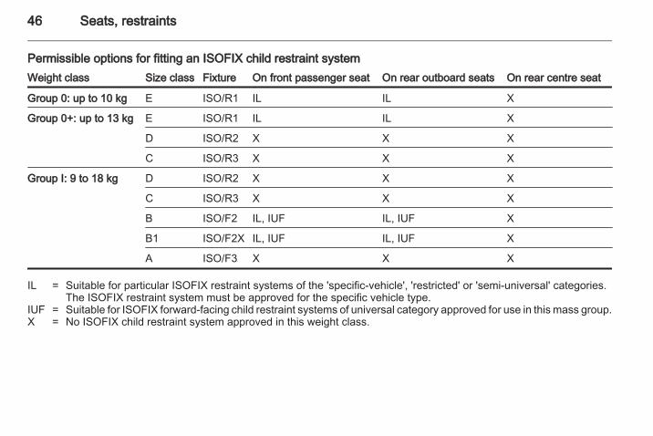
Permissible options for fitting an ISOFIX child restraint systemWeight class Size class Fixture On front passenger seat On rear outboard seats On rear centre seat
Group 0: up to 10 kg E ISO/R1 IL IL X
Group 0+: up to 13 kg E ISO/R1 IL IL X
D ISO/R2 X X X
C ISO/R3 X X X
Group I: 9 to 18 kg D ISO/R2 X X X
C ISO/R3 X X X
B ISO/F2 IL, IUF IL, IUF X
B1 ISO/F2X IL, IUF IL, IUF X
A ISO/F3 X X X
IL = Suitable for particular ISOFIX restraint systems of the 'specific-vehicle', 'restricted' or 'semi-universal' categories.The ISOFIX restraint system must be approved for the specific vehicle type.
IUF = Suitable for ISOFIX forward-facing child restraint systems of universal category approved for use in this mass group.X = No ISOFIX child restraint system approved in this weight class.
Seats, restraints 47
ISOFIX size class and seat deviceA – ISO/F3 = Forward-facing child restraint system for children of maximum size in the weight class 9 to 18 kg.B – ISO/F2 = Forward-facing child restraint system for smaller children in the weight class 9 to 18 kg.B1 – ISO/F2X = Forward-facing child restraint system for smaller children in the weight class 9 to 18 kg.C – ISO/R3 = Rear-facing child restraint system for children of maximum size in the weight class up to 13 kg.D – ISO/R2 = Rear-facing child restraint system for smaller children in the weight class up to 13 kg.E – ISO/R1 = Rear-facing child restraint system for young children in the weight class up to 13 kg.
48 Seats, restraints
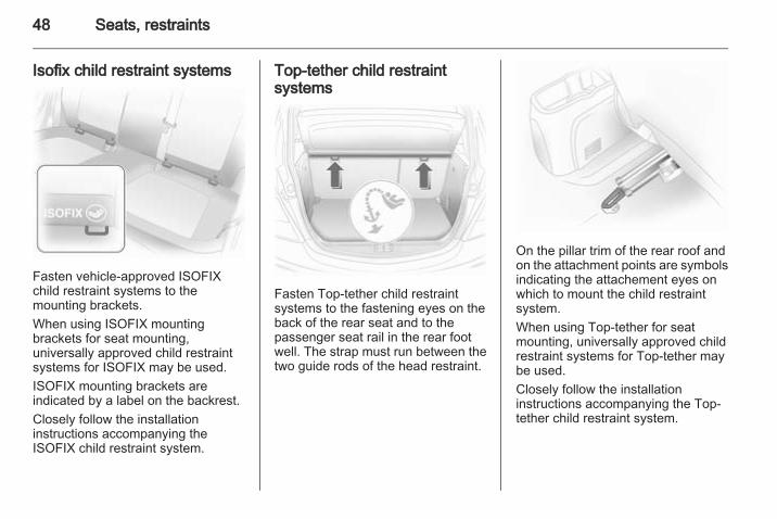
Isofix child restraint systems
Fasten vehicle-approved ISOFIXchild restraint systems to themounting brackets.When using ISOFIX mountingbrackets for seat mounting,universally approved child restraintsystems for ISOFIX may be used.ISOFIX mounting brackets areindicated by a label on the backrest.Closely follow the installationinstructions accompanying theISOFIX child restraint system.
Top-tether child restraintsystems
Fasten Top-tether child restraintsystems to the fastening eyes on theback of the rear seat and to thepassenger seat rail in the rear footwell. The strap must run between thetwo guide rods of the head restraint.
On the pillar trim of the rear roof andon the attachment points are symbolsindicating the attachement eyes onwhich to mount the child restraintsystem.When using Top-tether for seatmounting, universally approved childrestraint systems for Top-tether maybe used.Closely follow the installationinstructions accompanying the Top-tether child restraint system.
Storage 49
Storage
Storage compartments ................ 49Load compartment ....................... 58Roof rack system ......................... 63Loading information ..................... 64
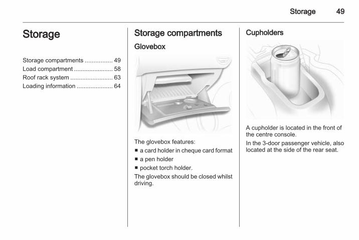
Storage compartmentsGlovebox
The glovebox features:■ a card holder in cheque card format■ a pen holder■ pocket torch holder.The glovebox should be closed whilstdriving.
Cupholders
A cupholder is located in the front ofthe centre console.In the 3-door passenger vehicle, alsolocated at the side of the rear seat.
50 Storage
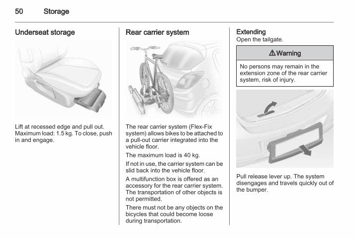
Underseat storage
Lift at recessed edge and pull out.Maximum load: 1.5 kg. To close, pushin and engage.
Rear carrier system
The rear carrier system (Flex-Fixsystem) allows bikes to be attached toa pull-out carrier integrated into thevehicle floor.The maximum load is 40 kg.If not in use, the carrier system can beslid back into the vehicle floor.A multifunction box is offered as anaccessory for the rear carrier system.The transportation of other objects isnot permitted.There must not be any objects on thebicycles that could become looseduring transportation.
ExtendingOpen the tailgate.
9 Warning
No persons may remain in theextension zone of the rear carriersystem, risk of injury.
Pull release lever up. The systemdisengages and travels quickly out ofthe bumper.
Storage 51
Completely pull out the rear carriersystem until it engages.Ensure that it is not possible to pushin the rear carrier system withoutpulling the release lever again
9 Warning
It is only permissible to fit objectsto the rear carrier system if thesystem has been correctlyengaged. If the rear carrier systemwill not engage correctly, do not fitobjects to the system and slide thesystem back. Seek the assistanceof a workshop.
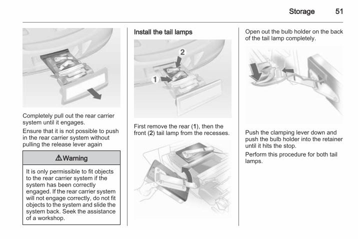
Install the tail lamps
First remove the rear (1), then thefront (2) tail lamp from the recesses.
Open out the bulb holder on the backof the tail lamp completely.
Push the clamping lever down andpush the bulb holder into the retaineruntil it hits the stop.Perform this procedure for both taillamps.
52 Storage
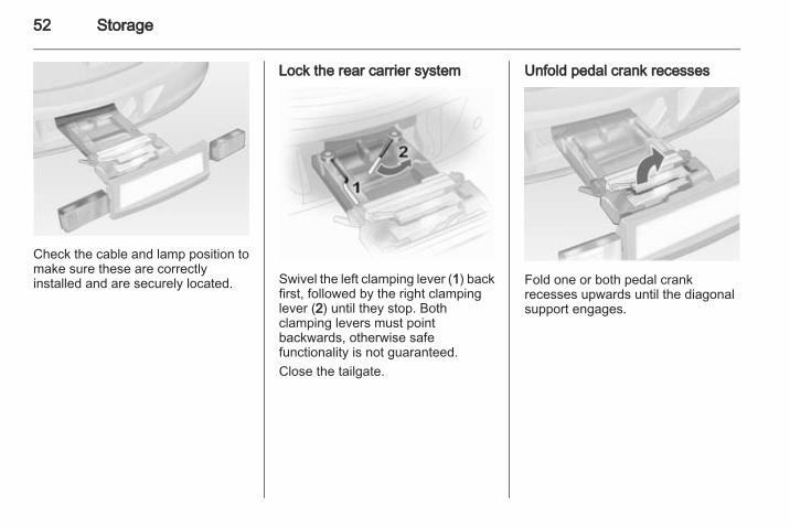
Check the cable and lamp position tomake sure these are correctlyinstalled and are securely located.
Lock the rear carrier system
Swivel the left clamping lever (1) backfirst, followed by the right clampinglever (2) until they stop. Bothclamping levers must pointbackwards, otherwise safefunctionality is not guaranteed.Close the tailgate.
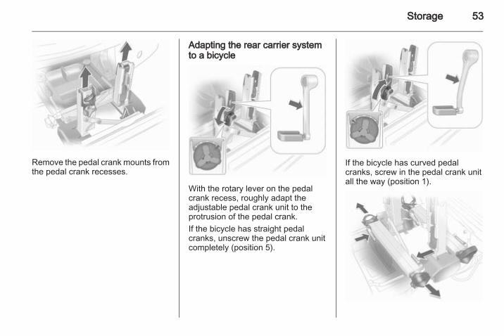
Unfold pedal crank recesses
Fold one or both pedal crankrecesses upwards until the diagonalsupport engages.
Storage 53
Remove the pedal crank mounts fromthe pedal crank recesses.
Adapting the rear carrier systemto a bicycle
With the rotary lever on the pedalcrank recess, roughly adapt theadjustable pedal crank unit to theprotrusion of the pedal crank.If the bicycle has straight pedalcranks, unscrew the pedal crank unitcompletely (position 5).
If the bicycle has curved pedalcranks, screw in the pedal crank unitall the way (position 1).
54 Storage
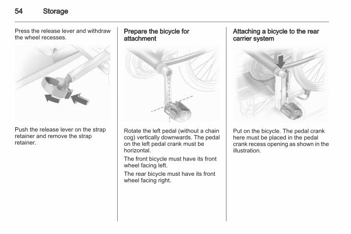
Press the release lever and withdrawthe wheel recesses.
Push the release lever on the strapretainer and remove the strapretainer.
Prepare the bicycle forattachment
Rotate the left pedal (without a chaincog) vertically downwards. The pedalon the left pedal crank must behorizontal.The front bicycle must have its frontwheel facing left.The rear bicycle must have its frontwheel facing right.
Attaching a bicycle to the rearcarrier system
Put on the bicycle. The pedal crankhere must be placed in the pedalcrank recess opening as shown in theillustration.
Storage 55
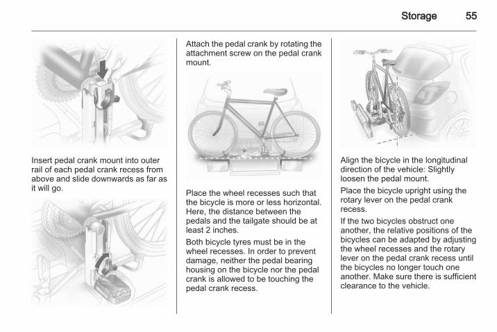
Insert pedal crank mount into outerrail of each pedal crank recess fromabove and slide downwards as far asit will go.
Attach the pedal crank by rotating theattachment screw on the pedal crankmount.
Place the wheel recesses such thatthe bicycle is more or less horizontal.Here, the distance between thepedals and the tailgate should be atleast 2 inches.Both bicycle tyres must be in thewheel recesses. In order to preventdamage, neither the pedal bearinghousing on the bicycle nor the pedalcrank is allowed to be touching thepedal crank recess.
Align the bicycle in the longitudinaldirection of the vehicle: Slightlyloosen the pedal mount.Place the bicycle upright using therotary lever on the pedal crankrecess.If the two bicycles obstruct oneanother, the relative positions of thebicycles can be adapted by adjustingthe wheel recesses and the rotarylever on the pedal crank recess untilthe bicycles no longer touch oneanother. Make sure there is sufficientclearance to the vehicle.
56 Storage
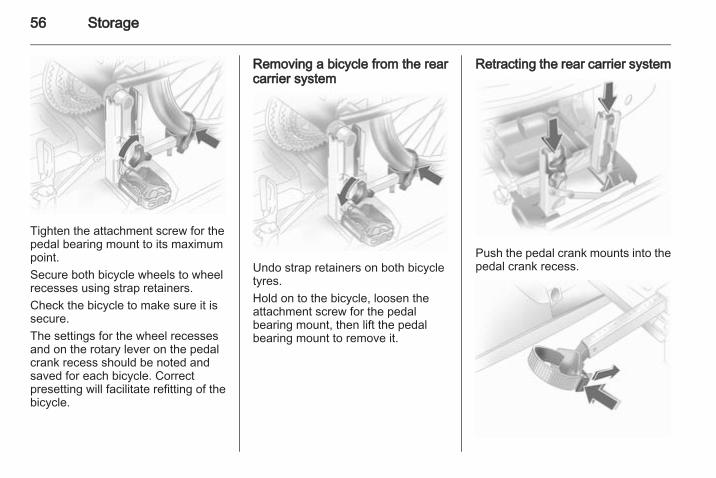
Tighten the attachment screw for thepedal bearing mount to its maximumpoint.Secure both bicycle wheels to wheelrecesses using strap retainers.Check the bicycle to make sure it issecure.The settings for the wheel recessesand on the rotary lever on the pedalcrank recess should be noted andsaved for each bicycle. Correctpresetting will facilitate refitting of thebicycle.
Removing a bicycle from the rearcarrier system
Undo strap retainers on both bicycletyres.Hold on to the bicycle, loosen theattachment screw for the pedalbearing mount, then lift the pedalbearing mount to remove it.
Retracting the rear carrier system
Push the pedal crank mounts into thepedal crank recess.
Storage 57
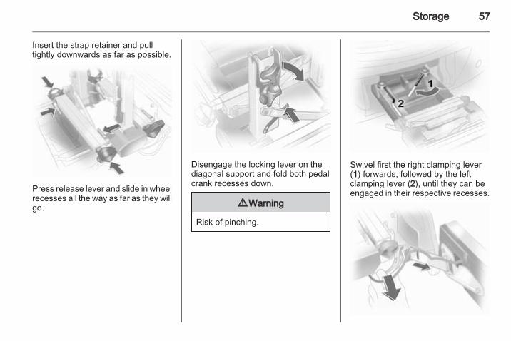
Insert the strap retainer and pulltightly downwards as far as possible.
Press release lever and slide in wheelrecesses all the way as far as they willgo.
Disengage the locking lever on thediagonal support and fold both pedalcrank recesses down.
9 Warning
Risk of pinching.
Swivel first the right clamping lever(1) forwards, followed by the leftclamping lever (2), until they can beengaged in their respective recesses.
58 Storage
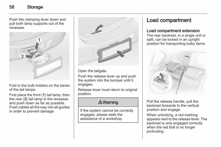
Push the clamping lever down andpull both lamp supports out of therecesses.
Fold in the bulb holders on the backsof the tail lamps.First place the front (1) tail lamp, thenthe rear (2) tail lamp in the recessesand push down as far as possible.Push cables all the way into all guidesin order to prevent damage.
Open the tailgate.Push the release lever up and pushthe system into the bumper until itengages.Release lever must return to originalposition.
9 Warning
If the system cannot be correctlyengaged, please seek theassistance of a workshop.
Load compartment
Load compartment extensionThe rear backrest, in a single unit orsplit, can be locked in an uprightposition for transporting bulky items.
Pull the release handle, pull thebackrest forwards to the verticalposition and engage.When unlocking, a red markingappears next to the release lever. Thebackrest is only engaged correctlywhen the red bolt is no longerprotruding.
Storage 59
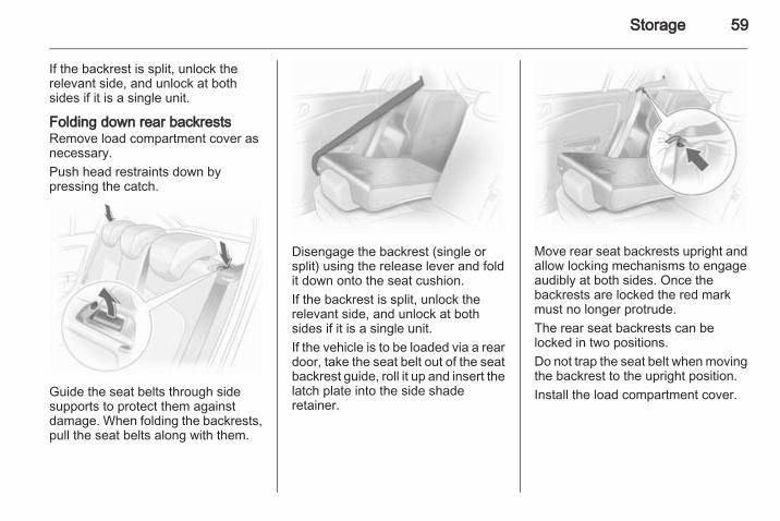
If the backrest is split, unlock therelevant side, and unlock at bothsides if it is a single unit.
Folding down rear backrestsRemove load compartment cover asnecessary.Push head restraints down bypressing the catch.
Guide the seat belts through sidesupports to protect them againstdamage. When folding the backrests,pull the seat belts along with them.
Disengage the backrest (single orsplit) using the release lever and foldit down onto the seat cushion.If the backrest is split, unlock therelevant side, and unlock at bothsides if it is a single unit.If the vehicle is to be loaded via a reardoor, take the seat belt out of the seatbackrest guide, roll it up and insert thelatch plate into the side shaderetainer.
Move rear seat backrests upright andallow locking mechanisms to engageaudibly at both sides. Once thebackrests are locked the red markmust no longer protrude.The rear seat backrests can belocked in two positions.Do not trap the seat belt when movingthe backrest to the upright position.Install the load compartment cover.
60 Storage
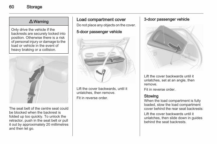
9 Warning
Only drive the vehicle if thebackrests are securely locked intoposition. Otherwise there is a riskof personal injury or damage to theload or vehicle in the event ofheavy braking or a collision.
The seat belt of the centre seat couldbe blocked when the backrest isfolded up too quickly. To unlock theretractor, push in the seat belt or pullit out by approximately 20 millimetresand then let go.
Load compartment coverDo not place any objects on the cover.
5-door passenger vehicle
Lift the cover backwards, until itunlatches, then remove.Fit in reverse order.
3-door passenger vehicle
Lift the cover backwards until itunlatches, set at an angle, thenremove.Fit in reverse order.
StowingWhen the load compartment is fullyloaded, stow the load compartmentcover behind the rear seat backrests:Lift the cover backwards until itunlatches, then slide down in guidesbehind the seat backrests.
Storage 61
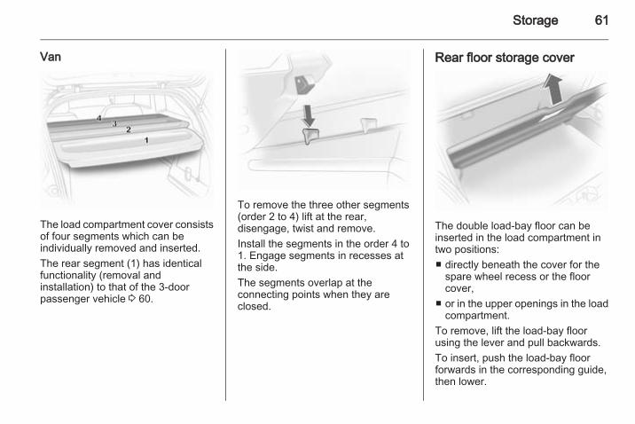
Van
The load compartment cover consistsof four segments which can beindividually removed and inserted.The rear segment (1) has identicalfunctionality (removal andinstallation) to that of the 3-doorpassenger vehicle 3 60.
To remove the three other segments(order 2 to 4) lift at the rear,disengage, twist and remove.Install the segments in the order 4 to1. Engage segments in recesses atthe side.The segments overlap at theconnecting points when they areclosed.
Rear floor storage cover
The double load-bay floor can beinserted in the load compartment intwo positions:■ directly beneath the cover for the
spare wheel recess or the floorcover,
■ or in the upper openings in the loadcompartment.
To remove, lift the load-bay floorusing the lever and pull backwards.To insert, push the load-bay floorforwards in the corresponding guide,then lower.
62 Storage
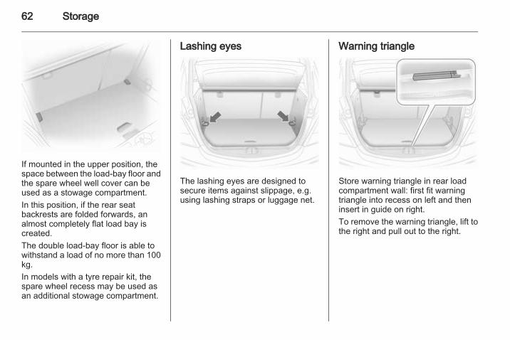
If mounted in the upper position, thespace between the load-bay floor andthe spare wheel well cover can beused as a stowage compartment.In this position, if the rear seatbackrests are folded forwards, analmost completely flat load bay iscreated.The double load-bay floor is able towithstand a load of no more than 100kg.In models with a tyre repair kit, thespare wheel recess may be used asan additional stowage compartment.
Lashing eyes
The lashing eyes are designed tosecure items against slippage, e.g.using lashing straps or luggage net.
Warning triangle
Store warning triangle in rear loadcompartment wall: first fit warningtriangle into recess on left and theninsert in guide on right.To remove the warning triangle, lift tothe right and pull out to the right.
Storage 63
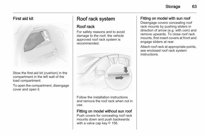
First aid kit
Stow the first-aid kit (cushion) in thecompartment in the left wall of theload compartment.To open the compartment, disengagecover and open it.
Roof rack systemRoof rackFor safety reasons and to avoiddamage to the roof, the vehicleapproved roof rack system isrecommended.
Follow the installation instructionsand remove the roof rack when not inuse.
Fitting on model without sun roofPush covers for concealing roof rackmounts down and push backwardswith a valve cap key 3 156.
Fitting on model with sun roofDisengage covers concealing roofrack mounts by pushing sliders indirection of arrow (e.g. with coin) andremove upwards. To close roof rackmounts, first insert covers at front andengage sliders at rear.Attach roof rack at appropriate points,see enclosed roof rack systeminstructions.
64 Storage
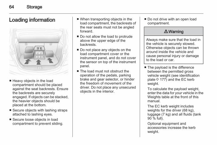
Loading information
■ Heavy objects in the loadcompartment should be placedagainst the seat backrests. Ensurethe backrests are securelyengaged. If objects can be stacked,the heavier objects should beplaced at the bottom.
■ Secure objects with lashing strapsattached to lashing eyes.
■ Secure loose objects in loadcompartment to prevent sliding.
■ When transporting objects in theload compartment, the backrests ofthe rear seats must not be angledforward.
■ Do not allow the load to protrudeabove the upper edge of thebackrests.
■ Do not place any objects on theload compartment cover or theinstrument panel, and do not coverthe sensor on top of the instrumentpanel.
■ The load must not obstruct theoperation of the pedals, parkingbrake and gear selector, or hinderthe freedom of movement of thedriver. Do not place any unsecuredobjects in the interior.
■ Do not drive with an open loadcompartment.
9 Warning
Always make sure that the load inthe vehicle is securely stowed.Otherwise objects can be thrownaround inside the vehicle andcause personal injury or damageto the load or car.
■ The payload is the differencebetween the permitted grossvehicle weight (see identificationplate 3 177) and the EC kerbweight.To calculate the payload weight,enter the data for your vehicle in theWeights table at the front of thismanual.The EC kerb weight includesweights for the driver (68 kg),luggage (7 kg) and all fluids (tank90 % full).Optional equipment andaccessories increase the kerbweight.
Storage 65
■ Driving with a roof load increasesthe sensitivity of the vehicle tocross-winds and has a detrimentaleffect on vehicle handling due tothe vehicle’s higher centre ofgravity. Distribute the load evenlyand secure it properly with retainingstraps. Adjust the tyre pressure andvehicle speed according to the loadconditions. Check and retighten thestraps frequently.The permissible roof load is 75 kg.The roof load is the combinedweight of the roof rack and the load.
66 Instruments and controls
Instruments andcontrols
Controls ....................................... 66Warning lights, gauges andindicators ..................................... 72Information displays ..................... 81Vehicle messages ........................ 85Trip computer ............................... 87Vehicle personalisation ................ 91
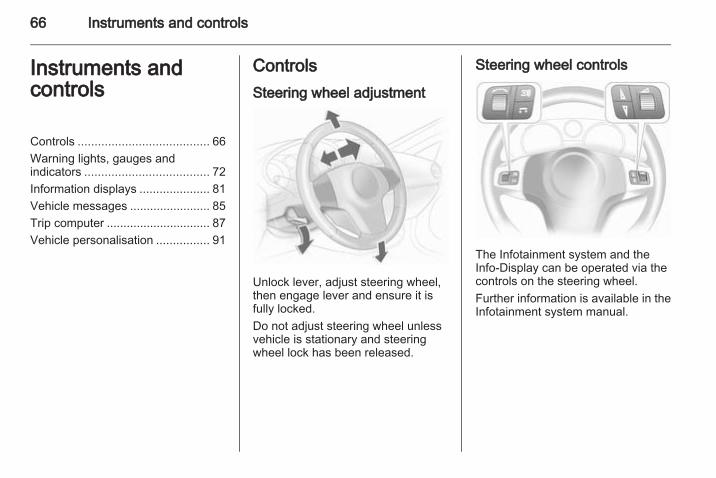
ControlsSteering wheel adjustment
Unlock lever, adjust steering wheel,then engage lever and ensure it isfully locked.Do not adjust steering wheel unlessvehicle is stationary and steeringwheel lock has been released.
Steering wheel controls
The Infotainment system and theInfo-Display can be operated via thecontrols on the steering wheel.Further information is available in theInfotainment system manual.
Instruments and controls 67
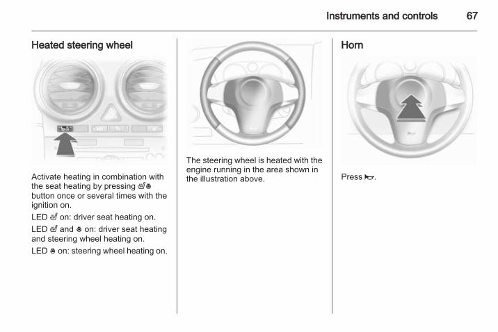
Heated steering wheel
Activate heating in combination withthe seat heating by pressing ß*button once or several times with theignition on.LED ß on: driver seat heating on.LED ß and * on: driver seat heatingand steering wheel heating on.LED * on: steering wheel heating on.
The steering wheel is heated with theengine running in the area shown inthe illustration above.
Horn
Press j.
68 Instruments and controls
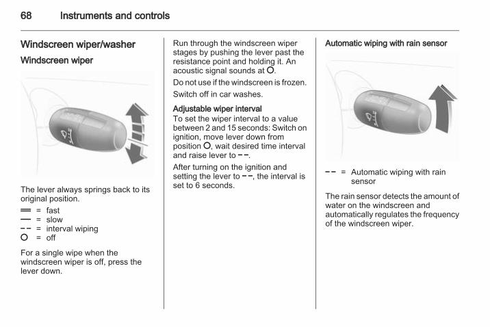
Windscreen wiper/washerWindscreen wiper
The lever always springs back to itsoriginal position.& = fast% = slow$ = interval wiping§ = off
For a single wipe when thewindscreen wiper is off, press thelever down.
Run through the windscreen wiperstages by pushing the lever past theresistance point and holding it. Anacoustic signal sounds at §.Do not use if the windscreen is frozen.Switch off in car washes.
Adjustable wiper intervalTo set the wiper interval to a valuebetween 2 and 15 seconds: Switch onignition, move lever down fromposition §, wait desired time intervaland raise lever to $.After turning on the ignition andsetting the lever to $, the interval isset to 6 seconds.
Automatic wiping with rain sensor
$ = Automatic wiping with rainsensor
The rain sensor detects the amount ofwater on the windscreen andautomatically regulates the frequencyof the windscreen wiper.
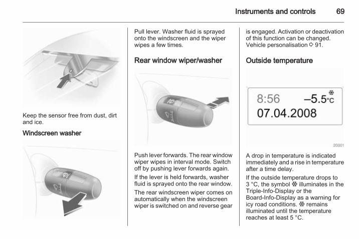
Instruments and controls 69
Keep the sensor free from dust, dirtand ice.
Windscreen washer
Pull lever. Washer fluid is sprayedonto the windscreen and the wiperwipes a few times.
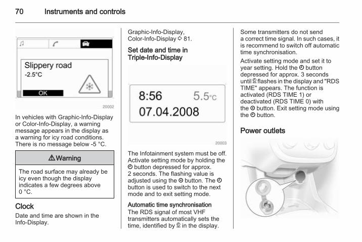
Rear window wiper/washer
Push lever forwards. The rear windowwiper wipes in interval mode. Switchoff by pushing lever forwards again.If the lever is held forwards, washerfluid is sprayed onto the rear window.The rear windscreen wiper comes onautomatically when the windscreenwiper is switched on and reverse gear
is engaged. Activation or deactivationof this function can be changed.Vehicle personalisation 3 91.
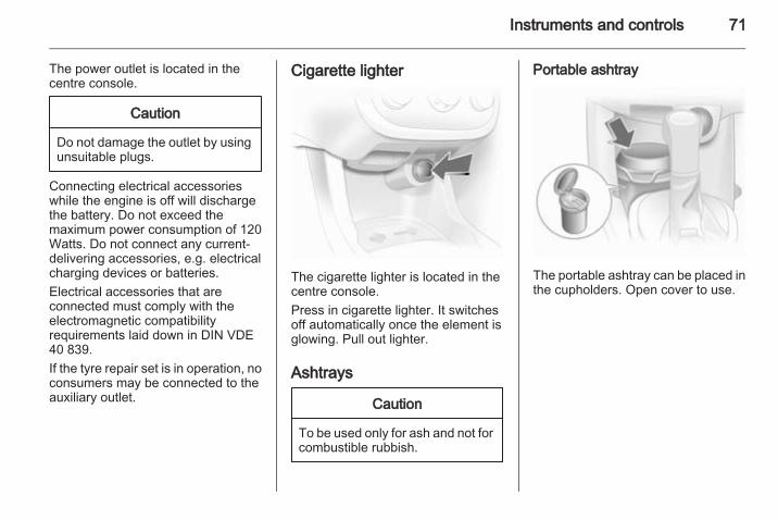
Outside temperature
A drop in temperature is indicatedimmediately and a rise in temperatureafter a time delay.If the outside temperature drops to3 °C, the symbol : illuminates in theTriple-Info-Display or theBoard-Info-Display as a warning foricy road conditions. : remainsilluminated until the temperaturereaches at least 5 °C.
70 Instruments and controls
In vehicles with Graphic-Info-Displayor Color-Info-Display, a warningmessage appears in the display asa warning for icy road conditions.There is no message below -5 °C.
9 Warning
The road surface may already beicy even though the displayindicates a few degrees above0 °C.
ClockDate and time are shown in theInfo-Display.
Graphic-Info-Display,Color-Info-Display 3 81.
Set date and time inTriple-Info-Display
The Infotainment system must be off.Activate setting mode by holding theÖ button depressed for approx.2 seconds. The flashing value isadjusted using the ; button. The Öbutton is used to switch to the nextmode and to exit setting mode.
Automatic time synchronisationThe RDS signal of most VHFtransmitters automatically sets thetime, identified by } in the display.
Some transmitters do not senda correct time signal. In such cases, itis recommend to switch off automatictime synchronisation.Activate setting mode and set it toyear setting. Hold the Ö buttondepressed for approx. 3 secondsuntil } flashes in the display and "RDSTIME" appears. The function isactivated (RDS TIME 1) ordeactivated (RDS TIME 0) withthe ; button. Exit setting mode usingthe Ö button.
Power outlets
Instruments and controls 71
The power outlet is located in thecentre console.
Caution
Do not damage the outlet by usingunsuitable plugs.
Connecting electrical accessorieswhile the engine is off will dischargethe battery. Do not exceed themaximum power consumption of 120Watts. Do not connect any current-delivering accessories, e.g. electricalcharging devices or batteries.Electrical accessories that areconnected must comply with theelectromagnetic compatibilityrequirements laid down in DIN VDE40 839.If the tyre repair set is in operation, noconsumers may be connected to theauxiliary outlet.
Cigarette lighter
The cigarette lighter is located in thecentre console.Press in cigarette lighter. It switchesoff automatically once the element isglowing. Pull out lighter.
Ashtrays
Caution
To be used only for ash and not forcombustible rubbish.
Portable ashtray
The portable ashtray can be placed inthe cupholders. Open cover to use.
72 Instruments and controls
Warning lights, gaugesand indicatorsInstrument clusterIn some versions, the needles of theinstruments briefly rotate to the endposition when the ignition is switchedon.
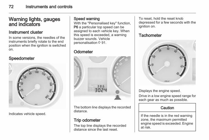
Speedometer
Indicates vehicle speed.
Speed warningWith the "Personalised key" function,P6 a particular top speed can beassigned to each vehicle key. Whenthis speed is exceeded, a warningbuzzer sounds. Vehiclepersonalisation 3 91.
Odometer
The bottom line displays the recordeddistance.
Trip odometerThe top line displays the recordeddistance since the last reset.
To reset, hold the reset knobdepressed for a few seconds with theignition on.
Tachometer
Displays the engine speed.Drive in a low engine speed range foreach gear as much as possible.
Caution
If the needle is in the red warningzone, the maximum permittedengine speed is exceeded. Engineat risk.
Instruments and controls 73
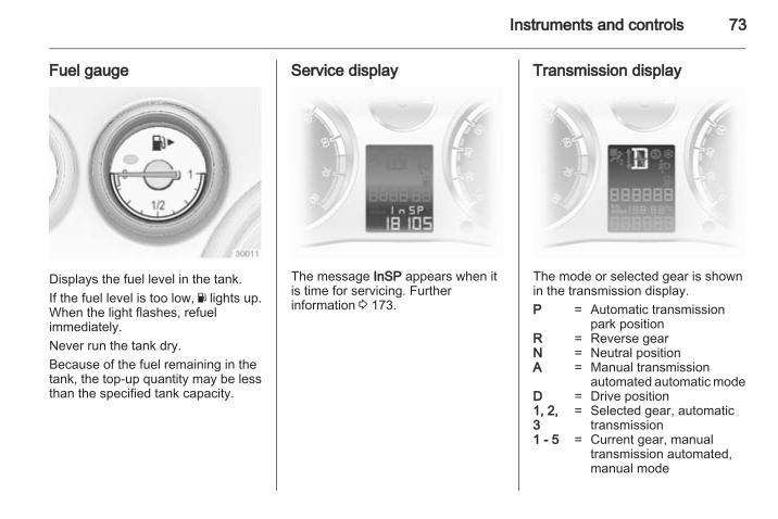
Fuel gauge
Displays the fuel level in the tank.If the fuel level is too low, Y lights up.When the light flashes, refuelimmediately.Never run the tank dry.Because of the fuel remaining in thetank, the top-up quantity may be lessthan the specified tank capacity.
Service display
The message InSP appears when itis time for servicing. Furtherinformation 3 173.
Transmission display
The mode or selected gear is shownin the transmission display.P = Automatic transmission
park positionR = Reverse gearN = Neutral positionA = Manual transmission
automated automatic modeD = Drive position1, 2,3
= Selected gear, automatictransmission
1 - 5 = Current gear, manualtransmission automated,manual mode
74 Instruments and controls
Control indicatorsThe control indicators described arenot present in all vehicles. Thedescription applies to all instrumentversions. When the ignition isswitched on, most control indicatorswill illuminate briefly as a functionalitytest.The control indicator colours mean:red = danger, important
reminderyellow = warning, information, faultgreen = confirmation of activationblue = confirmation of activation
Instruments and controls 75
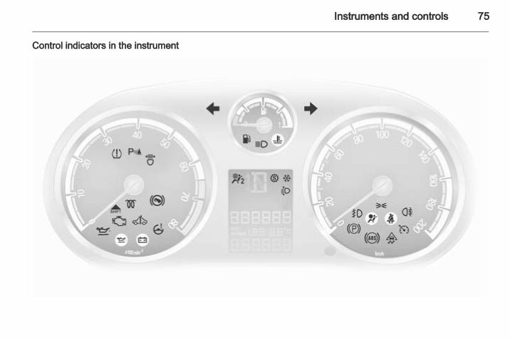
Control indicators in the instrument
76 Instruments and controls
Turn signalO illuminates or flashes green.
IlluminatesThe control indicator illuminatesbriefly when the parking lights areswitched on.
FlashesThe control indicator flashes if a turnsignal or the hazard warning flashersare activated.Rapid flashing: failure of a turn signallight or associated fuse, failure of turnsignal light on trailer.Bulb replacement 3 140. Fuses3 152. Turn signals 3 96.
Seat belt reminderX illuminates or flashes red.
IlluminatesAfter the ignition is switched on untilthe seat belt is fastened.
FlashesAfter starting off until the seat belt isfastened.
Fastening the seat belt 3 37.
Airbag and belt tensionersv illuminates red.When the ignition is switched on, thecontrol indicator illuminates forapprox. 4 seconds. If it does notilluminate, does not go out after4 seconds or illuminates whilstdriving, there is a fault in the belttensioner or the airbags. In this casethe LEDs in the button W will alsoflash.The airbags and belt tensionersmay fail to trigger in the event of anaccident.Deployment of the belt tensioners orairbags is indicated by continuousillumination of v.
9 Warning
Have the cause of the faultremedied immediately bya workshop.
Airbag system, belt tensioners 3 38,3 36.
Airbag deactivationW illuminates together with the LEDsin the button W: airbag deactivated3 42.W flashes: the system can beactivated or deactivated within 15seconds of switching on the ignition3 42.
Charging systemp illuminates or flashes red.Illuminates when the ignition isswitched on and goes out shortly afterthe engine starts.
Illuminates when the engine isrunningStop, switch off engine. Battery is notcharging. Engine cooling may beinterrupted. In diesel engines, powerto the brake servo unit may be cut.Seek the assistance of a workshop.
Instruments and controls 77
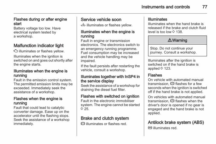
Flashes during or after enginestartBattery voltage too low. Haveelectrical system tested bya workshop.
Malfunction indicator lightZ illuminates or flashes yellow.Illuminates when the ignition isswitched on and goes out shortly afterthe engine starts.
Illuminates when the engine isrunningFault in the emission control system.The permitted emission limits may beexceeded. Immediately seek theassistance of a workshop.
Flashes when the engine isrunningFault that could lead to catalyticconverter damage. Ease up on theaccelerator until the flashing stops.Seek the assistance of a workshopimmediately.
Service vehicle soonA illuminates or flashes yellow.
Illuminates when the engine isrunningFault in engine or transmissionelectronics. The electronics switch toan emergency running programme.Fuel consumption may be increasedand the vehicle handling may beimpaired.If the fault persists after restarting thevehicle, consult a workshop.
Illuminates together with InSP4 inthe service displaySeek the assistance of a workshop fordraining the diesel fuel filter.
Flashes with switched on ignitionFault in the electronic immobilisersystem. The engine cannot be started3 25.
Brake and clutch systemR illuminates or flashes red.
IlluminatesIlluminates when the hand brake isreleased if the brake and clutch fluidlevel is too low 3 138.
9 Warning
Stop. Do not continue yourjourney. Consult a workshop.
Illuminates after the ignition isswitched on if the hand brake isapplied 3 123.
FlashesOn vehicle with automated manualtransmission, R flashes for a fewseconds when the ignition is switchedoff if the hand brake is not applied.On vehicles with automated manualtransmission, R flashes when thedriver's door is opened if no gear isengaged and the hand brake is notapplied.
Antilock brake system (ABS)u illuminates red.
78 Instruments and controls
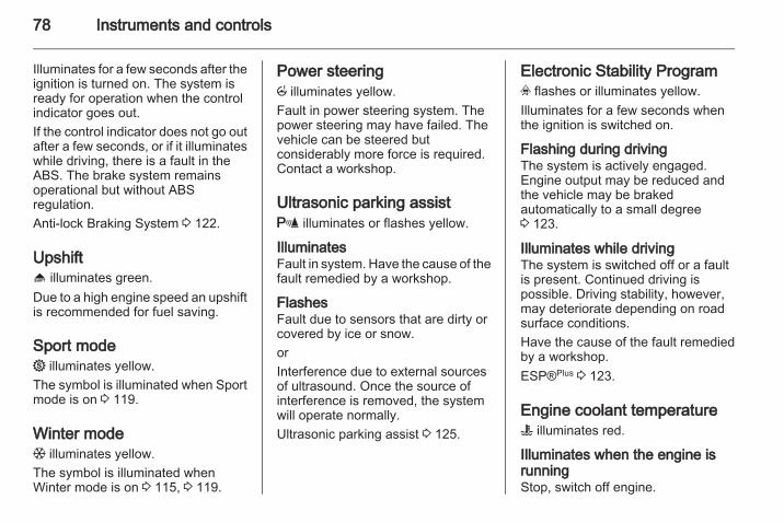
Illuminates for a few seconds after theignition is turned on. The system isready for operation when the controlindicator goes out.If the control indicator does not go outafter a few seconds, or if it illuminateswhile driving, there is a fault in theABS. The brake system remainsoperational but without ABSregulation.Anti-lock Braking System 3 122.
Upshift[ illuminates green.Due to a high engine speed an upshiftis recommended for fuel saving.
Sport mode1 illuminates yellow.The symbol is illuminated when Sportmode is on 3 119.
Winter modeT illuminates yellow.The symbol is illuminated whenWinter mode is on 3 115, 3 119.
Power steeringp illuminates yellow.Fault in power steering system. Thepower steering may have failed. Thevehicle can be steered butconsiderably more force is required.Contact a workshop.
Ultrasonic parking assistr illuminates or flashes yellow.
IlluminatesFault in system. Have the cause of thefault remedied by a workshop.
FlashesFault due to sensors that are dirty orcovered by ice or snow.orInterference due to external sourcesof ultrasound. Once the source ofinterference is removed, the systemwill operate normally.Ultrasonic parking assist 3 125.
Electronic Stability Programv flashes or illuminates yellow.Illuminates for a few seconds whenthe ignition is switched on.
Flashing during drivingThe system is actively engaged.Engine output may be reduced andthe vehicle may be brakedautomatically to a small degree3 123.
Illuminates while drivingThe system is switched off or a faultis present. Continued driving ispossible. Driving stability, however,may deteriorate depending on roadsurface conditions.Have the cause of the fault remediedby a workshop.ESP®Plus 3 123.
Engine coolant temperatureW illuminates red.
Illuminates when the engine isrunningStop, switch off engine.
Instruments and controls 79
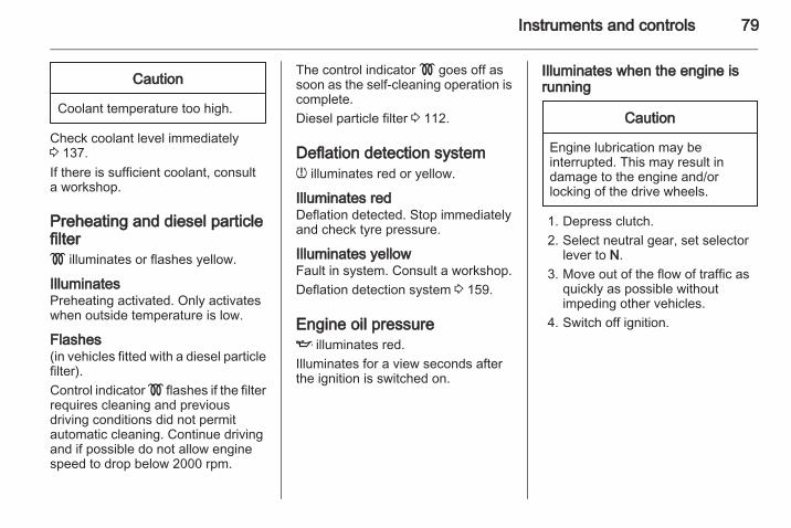
Caution
Coolant temperature too high.
Check coolant level immediately3 137.If there is sufficient coolant, consulta workshop.
Preheating and diesel particlefilter! illuminates or flashes yellow.
IlluminatesPreheating activated. Only activateswhen outside temperature is low.
Flashes(in vehicles fitted with a diesel particlefilter).Control indicator ! flashes if the filterrequires cleaning and previousdriving conditions did not permitautomatic cleaning. Continue drivingand if possible do not allow enginespeed to drop below 2000 rpm.
The control indicator ! goes off assoon as the self-cleaning operation iscomplete.Diesel particle filter 3 112.
Deflation detection systemw illuminates red or yellow.
Illuminates redDeflation detected. Stop immediatelyand check tyre pressure.
Illuminates yellowFault in system. Consult a workshop.Deflation detection system 3 159.
Engine oil pressureI illuminates red.Illuminates for a view seconds afterthe ignition is switched on.
Illuminates when the engine isrunning
Caution
Engine lubrication may beinterrupted. This may result indamage to the engine and/orlocking of the drive wheels.
1. Depress clutch.2. Select neutral gear, set selector
lever to N.3. Move out of the flow of traffic as
quickly as possible withoutimpeding other vehicles.
4. Switch off ignition.
80 Instruments and controls
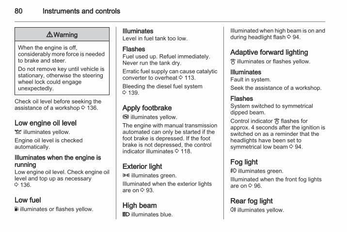
9 Warning
When the engine is off,considerably more force is neededto brake and steer.Do not remove key until vehicle isstationary, otherwise the steeringwheel lock could engageunexpectedly.
Check oil level before seeking theassistance of a workshop 3 136.
Low engine oil levelS illuminates yellow.Engine oil level is checkedautomatically.
Illuminates when the engine isrunningLow engine oil level. Check engine oillevel and top up as necessary3 136.
Low fuelY illuminates or flashes yellow.
IlluminatesLevel in fuel tank too low.
FlashesFuel used up. Refuel immediately.Never run the tank dry.Erratic fuel supply can cause catalyticconverter to overheat 3 113.Bleeding the diesel fuel system3 139.
Apply footbrakej illuminates yellow.The engine with manual transmissionautomated can only be started if thefoot brake is depressed. If the footbrake is not depressed, the controlindicator illuminates 3 118.
Exterior light8 illuminates green.Illuminated when the exterior lightsare on 3 93.
High beamP illuminates blue.
Illuminated when high beam is on andduring headlight flash 3 94.
Adaptive forward lightingB illuminates or flashes yellow.
IlluminatesFault in system.Seek the assistance of a workshop.
FlashesSystem switched to symmetricaldipped beam.Control indicator B flashes forapprox. 4 seconds after the ignition isswitched on as a reminder that theheadlights have been set tosymmetrical low beam 3 94.
Fog light> illuminates green.Illuminated when the front fog lightsare on 3 96.
Rear fog lightr illuminates yellow.
Instruments and controls 81
Illuminated when the rear fog light ison 3 97.
Cruise controlm illuminates or flashes green.
IlluminatesIlluminates when the system is on3 124.
FlashesCruise control was enabled withoutdepressing the brake pedalbeforehand.
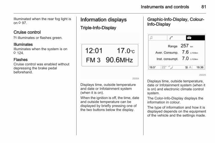
Information displaysTriple-Info-Display
Displays time, outside temperatureand date or Infotainment system(when it is on).When the ignition is off, the time, dateand outside temperature can bedisplayed by briefly pressing one ofthe two buttons below the display.
Graphic-Info-Display, Colour-Info-Display
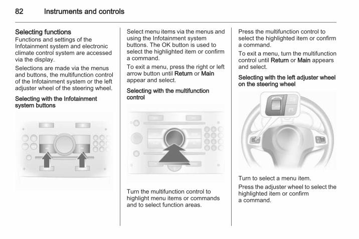
Displays time, outside temperature,date or Infotainment system (when itis on) and electronic climate controlsystem.The Color-Info-Display displays theinformation in colour.The type of information and how it isdisplayed depends on the equipmentof the vehicle and the settings made.
82 Instruments and controls
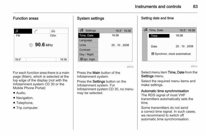
Selecting functionsFunctions and settings of theInfotainment system and electronicclimate control system are accessedvia the display.Selections are made via the menusand buttons, the multifunction controlof the Infotainment system or the leftadjuster wheel of the steering wheel.
Selecting with the Infotainmentsystem buttons
Select menu items via the menus andusing the Infotainment systembuttons. The OK button is used toselect the highlighted item or confirma command.To exit a menu, press the right or leftarrow button until Return or Mainappear and select.
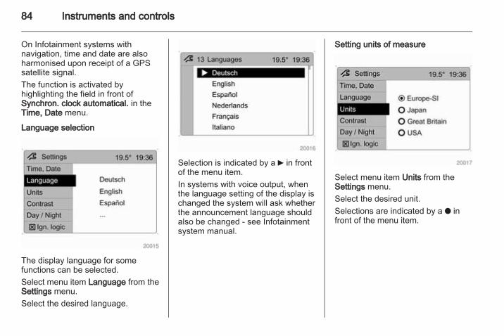
Selecting with the multifunctioncontrol
Turn the multifunction control tohighlight menu items or commandsand to select function areas.
Press the multifunction control toselect the highlighted item or confirma command.To exit a menu, turn the multifunctioncontrol until Return or Main appearsand select.
Selecting with the left adjuster wheelon the steering wheel
Turn to select a menu item.Press the adjuster wheel to select thehighlighted item or confirma command.
Instruments and controls 83
Function areas
For each function area there is a mainpage (Main), which is selected at thetop edge of the display (not with theInfotainment system CD 30 or theMobile Phone Portal):■ Audio,■ Navigation,■ Telephone,■ Trip computer.
System settings
Press the Main button of theInfotainment system.Press the Settings button on theInfotainment system. ForInfotainment system CD 30, no menumay be selected.
Setting date and time
Select menu item Time, Date from theSettings menu.Select the required menu items andmake settings.
Automatic time synchronisationThe RDS signal of most VHFtransmitters automatically sets thetime.Some transmitters do not senda correct time signal. In such cases,we recommend to switch offautomatic time synchronisation.
84 Instruments and controls
On Infotainment systems withnavigation, time and date are alsoharmonised upon receipt of a GPSsatellite signal.The function is activated byhighlighting the field in front ofSynchron. clock automatical. in theTime, Date menu.
Language selection
The display language for somefunctions can be selected.Select menu item Language from theSettings menu.Select the desired language.
Selection is indicated by a 6 in frontof the menu item.In systems with voice output, whenthe language setting of the display ischanged the system will ask whetherthe announcement language shouldalso be changed - see Infotainmentsystem manual.
Setting units of measure
Select menu item Units from theSettings menu.Select the desired unit.Selections are indicated by a o infront of the menu item.
Instruments and controls 85
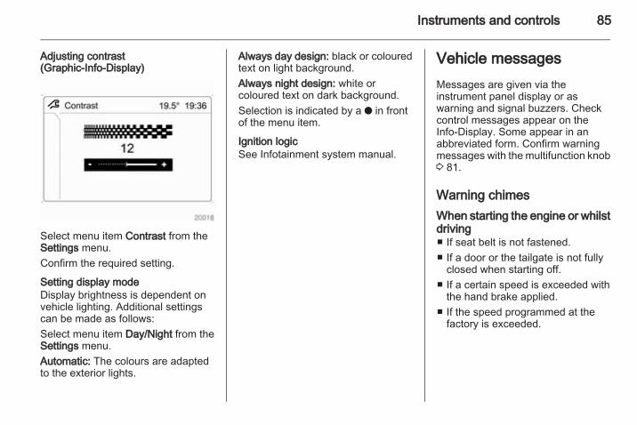
Adjusting contrast(Graphic-Info-Display)
Select menu item Contrast from theSettings menu.Confirm the required setting.
Setting display modeDisplay brightness is dependent onvehicle lighting. Additional settingscan be made as follows:Select menu item Day/Night from theSettings menu.Automatic: The colours are adaptedto the exterior lights.
Always day design: black or colouredtext on light background.Always night design: white orcoloured text on dark background.Selection is indicated by a o in frontof the menu item.
Ignition logicSee Infotainment system manual.
Vehicle messagesMessages are given via theinstrument panel display or aswarning and signal buzzers. Checkcontrol messages appear on theInfo-Display. Some appear in anabbreviated form. Confirm warningmessages with the multifunction knob3 81.
Warning chimesWhen starting the engine or whilstdriving■ If seat belt is not fastened.■ If a door or the tailgate is not fully
closed when starting off.■ If a certain speed is exceeded with
the hand brake applied.■ If the speed programmed at the
factory is exceeded.
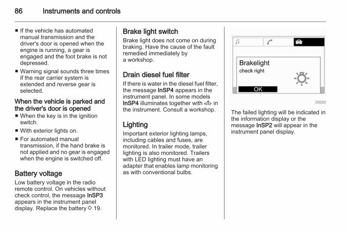
86 Instruments and controls
■ If the vehicle has automatedmanual transmission and thedriver's door is opened when theengine is running, a gear isengaged and the foot brake is notdepressed.
■ Warning signal sounds three timesif the rear carrier system isextended and reverse gear isselected.
When the vehicle is parked andthe driver's door is opened■ When the key is in the ignition
switch.■ With exterior lights on.■ For automated manual
transmission, if the hand brake isnot applied and no gear is engagedwhen the engine is switched off.
Battery voltageLow battery voltage in the radioremote control. On vehicles withoutcheck control, the message InSP3appears in the instrument paneldisplay. Replace the battery 3 19.
Brake light switchBrake light does not come on duringbraking. Have the cause of the faultremedied immediately bya workshop.
Drain diesel fuel filterIf there is water in the diesel fuel filter,the message InSP4 appears in theinstrument panel. In some modelsInSP4 illuminates together with A inthe instrument. Consult a workshop.
LightingImportant exterior lighting lamps,including cables and fuses, aremonitored. In trailer mode, trailerlighting is also monitored. Trailerswith LED lighting must have anadapter that enables lamp monitoringas with conventional bulbs.
The failed lighting will be indicated inthe information display or themessage InSP2 will appear in theinstrument panel display.
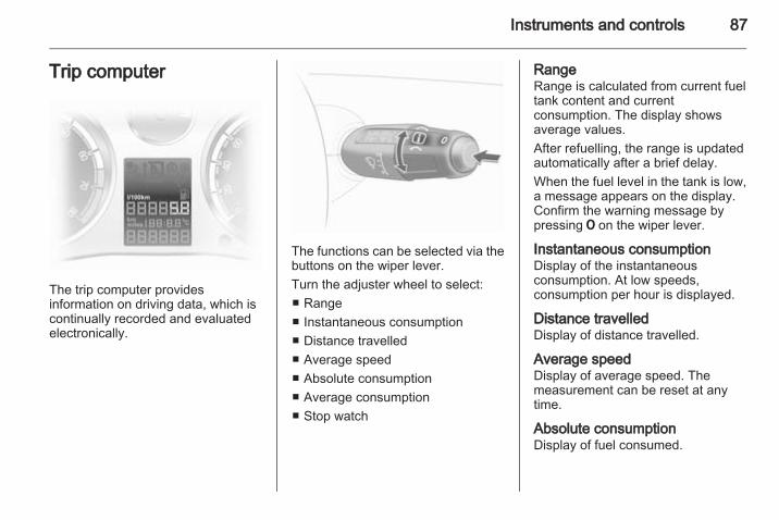
Instruments and controls 87
Trip computer
The trip computer providesinformation on driving data, which iscontinually recorded and evaluatedelectronically.
The functions can be selected via thebuttons on the wiper lever.Turn the adjuster wheel to select:■ Range■ Instantaneous consumption■ Distance travelled■ Average speed■ Absolute consumption■ Average consumption■ Stop watch
RangeRange is calculated from current fueltank content and currentconsumption. The display showsaverage values.After refuelling, the range is updatedautomatically after a brief delay.When the fuel level in the tank is low,a message appears on the display.Confirm the warning message bypressing 7 on the wiper lever.
Instantaneous consumptionDisplay of the instantaneousconsumption. At low speeds,consumption per hour is displayed.
Distance travelledDisplay of distance travelled.
Average speedDisplay of average speed. Themeasurement can be reset at anytime.
Absolute consumptionDisplay of fuel consumed.
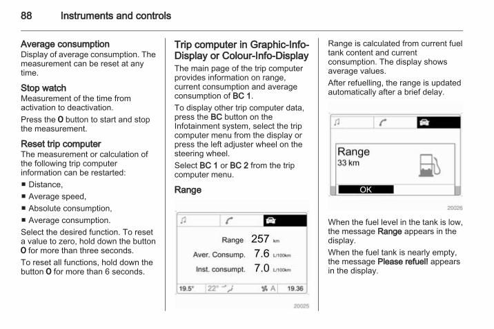
88 Instruments and controls
Average consumptionDisplay of average consumption. Themeasurement can be reset at anytime.
Stop watchMeasurement of the time fromactivation to deactivation.Press the 7 button to start and stopthe measurement.
Reset trip computerThe measurement or calculation ofthe following trip computerinformation can be restarted:■ Distance,■ Average speed,■ Absolute consumption,■ Average consumption.Select the desired function. To reseta value to zero, hold down the button7 for more than three seconds.To reset all functions, hold down thebutton 7 for more than 6 seconds.
Trip computer in Graphic-Info-Display or Colour-Info-DisplayThe main page of the trip computerprovides information on range,current consumption and averageconsumption of BC 1.To display other trip computer data,press the BC button on theInfotainment system, select the tripcomputer menu from the display orpress the left adjuster wheel on thesteering wheel.Select BC 1 or BC 2 from the tripcomputer menu.
Range
Range is calculated from current fueltank content and currentconsumption. The display showsaverage values.After refuelling, the range is updatedautomatically after a brief delay.
When the fuel level in the tank is low,the message Range appears in thedisplay.When the fuel tank is nearly empty,the message Please refuel! appearsin the display.
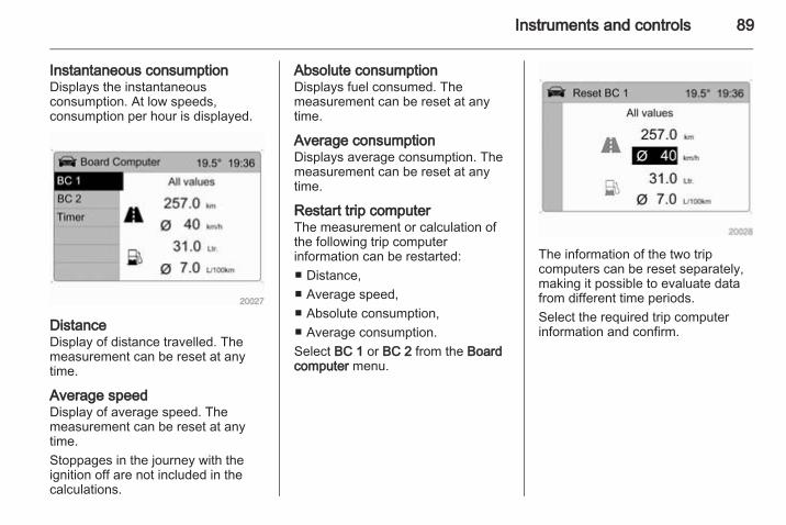
Instruments and controls 89
Instantaneous consumptionDisplays the instantaneousconsumption. At low speeds,consumption per hour is displayed.
DistanceDisplay of distance travelled. Themeasurement can be reset at anytime.
Average speedDisplay of average speed. Themeasurement can be reset at anytime.Stoppages in the journey with theignition off are not included in thecalculations.
Absolute consumptionDisplays fuel consumed. Themeasurement can be reset at anytime.
Average consumptionDisplays average consumption. Themeasurement can be reset at anytime.
Restart trip computerThe measurement or calculation ofthe following trip computerinformation can be restarted:■ Distance,■ Average speed,■ Absolute consumption,■ Average consumption.Select BC 1 or BC 2 from the Boardcomputer menu.
The information of the two tripcomputers can be reset separately,making it possible to evaluate datafrom different time periods.Select the required trip computerinformation and confirm.
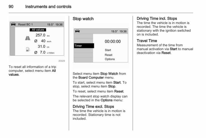
90 Instruments and controls
To reset all information of a tripcomputer, select menu item Allvalues.
Stop watch
Select menu item Stop Watch fromthe Board Computer menu.To start, select menu item Start. Tostop, select menu item Stop.To reset, select menu item Reset.The relevant stop watch display canbe selected in the Options menu:
Driving Time excl. StopsThe time the vehicle is in motion isrecorded. Stationary time is notincluded.
Driving Time incl. StopsThe time the vehicle is in motion isrecorded. The time the vehicle isstationary with the ignition switchedon is included.
Travel TimeMeasurement of the time frommanual activation via Start to manualdeactivation via Reset.
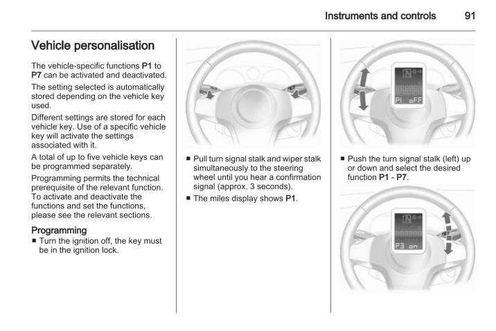
Instruments and controls 91
Vehicle personalisationThe vehicle-specific functions P1 toP7 can be activated and deactivated.The setting selected is automaticallystored depending on the vehicle keyused.Different settings are stored for eachvehicle key. Use of a specific vehiclekey will activate the settingsassociated with it.A total of up to five vehicle keys canbe programmed separately.Programming permits the technicalprerequisite of the relevant function.To activate and deactivate thefunctions and set the functions,please see the relevant sections.
Programming■ Turn the ignition off, the key must
be in the ignition lock.
■ Pull turn signal stalk and wiper stalksimultaneously to the steeringwheel until you hear a confirmationsignal (approx. 3 seconds).
■ The miles display shows P1.
■ Push the turn signal stalk (left) upor down and select the desiredfunction P1 - P7.
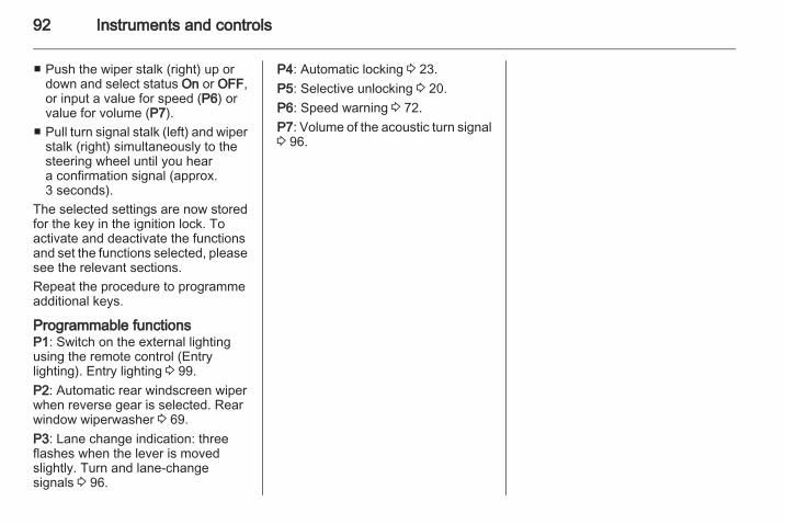
92 Instruments and controls
■ Push the wiper stalk (right) up ordown and select status On or OFF,or input a value for speed (P6) orvalue for volume (P7).
■ Pull turn signal stalk (left) and wiperstalk (right) simultaneously to thesteering wheel until you heara confirmation signal (approx.3 seconds).
The selected settings are now storedfor the key in the ignition lock. Toactivate and deactivate the functionsand set the functions selected, pleasesee the relevant sections.Repeat the procedure to programmeadditional keys.
Programmable functionsP1: Switch on the external lightingusing the remote control (Entrylighting). Entry lighting 3 99.P2: Automatic rear windscreen wiperwhen reverse gear is selected. Rearwindow wiperwasher 3 69.P3: Lane change indication: threeflashes when the lever is movedslightly. Turn and lane-changesignals 3 96.
P4: Automatic locking 3 23.P5: Selective unlocking 3 20.P6: Speed warning 3 72.P7: Volume of the acoustic turn signal3 96.
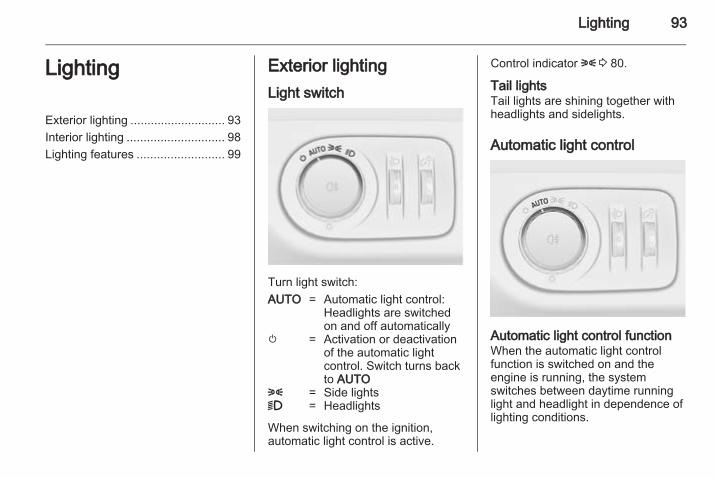
Lighting 93
Lighting
Exterior lighting ............................ 93Interior lighting ............................. 98Lighting features .......................... 99
Exterior lightingLight switch
Turn light switch:AUTO = Automatic light control:
Headlights are switchedon and off automatically
m = Activation or deactivationof the automatic lightcontrol. Switch turns backto AUTO
8 = Side lights9 = Headlights
When switching on the ignition,automatic light control is active.
Control indicator 8 3 80.
Tail lightsTail lights are shining together withheadlights and sidelights.
Automatic light control
Automatic light control functionWhen the automatic light controlfunction is switched on and theengine is running, the systemswitches between daytime runninglight and headlight in dependence oflighting conditions.
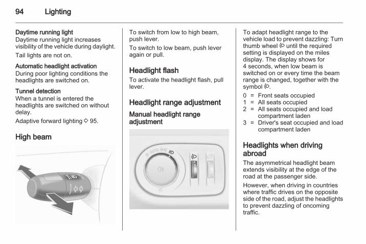
94 Lighting
Daytime running lightDaytime running light increasesvisibility of the vehicle during daylight.Tail lights are not on.
Automatic headlight activationDuring poor lighting conditions theheadlights are switched on.
Tunnel detectionWhen a tunnel is entered theheadlights are switched on withoutdelay.Adaptive forward lighting 3 95.
High beam
To switch from low to high beam,push lever.To switch to low beam, push leveragain or pull.
Headlight flashTo activate the headlight flash, pulllever.
Headlight range adjustmentManual headlight rangeadjustment
To adapt headlight range to thevehicle load to prevent dazzling: Turnthumb wheel ? until the requiredsetting is displayed on the milesdisplay. The display shows for4 seconds, when low beam isswitched on or every time the beamrange is changed, together with thesymbol ?.0 = Front seats occupied1 = All seats occupied2 = All seats occupied and load
compartment laden3 = Driver's seat occupied and load
compartment laden
Headlights when drivingabroadThe asymmetrical headlight beamextends visibility at the edge of theroad at the passenger side.However, when driving in countrieswhere traffic drives on the oppositeside of the road, adjust the headlightsto prevent dazzling of oncomingtraffic.
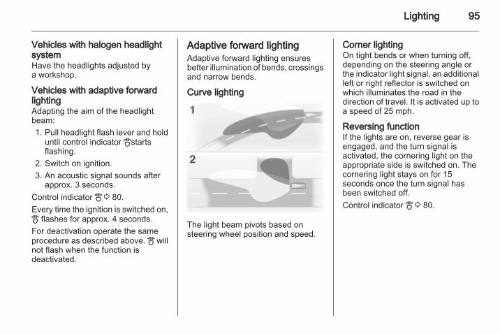
Lighting 95
Vehicles with halogen headlightsystemHave the headlights adjusted bya workshop.
Vehicles with adaptive forwardlightingAdapting the aim of the headlightbeam:1. Pull headlight flash lever and hold
until control indicator Bstartsflashing.
2. Switch on ignition.3. An acoustic signal sounds after
approx. 3 seconds.Control indicator B 3 80.Every time the ignition is switched on,B flashes for approx. 4 seconds.For deactivation operate the sameprocedure as described above. B willnot flash when the function isdeactivated.
Adaptive forward lightingAdaptive forward lighting ensuresbetter illumination of bends, crossingsand narrow bends.
Curve lighting
The light beam pivots based onsteering wheel position and speed.
Corner lightingOn tight bends or when turning off,depending on the steering angle orthe indicator light signal, an additionalleft or right reflector is switched onwhich illuminates the road in thedirection of travel. It is activated up toa speed of 25 mph.
Reversing functionIf the lights are on, reverse gear isengaged, and the turn signal isactivated, the cornering light on theappropriate side is switched on. Thecornering light stays on for 15seconds once the turn signal hasbeen switched off.Control indicator B 3 80.
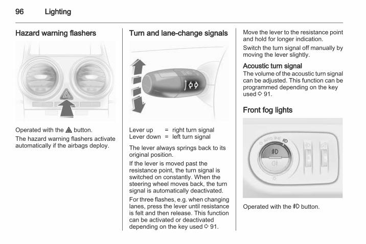
96 Lighting
Hazard warning flashers
Operated with the ¨ button.The hazard warning flashers activateautomatically if the airbags deploy.
Turn and lane-change signals
Lever up = right turn signalLever down = left turn signal
The lever always springs back to itsoriginal position.If the lever is moved past theresistance point, the turn signal isswitched on constantly. When thesteering wheel moves back, the turnsignal is automatically deactivated.For three flashes, e.g. when changinglanes, press the lever until resistanceis felt and then release. This functioncan be activated or deactivateddepending on the key used 3 91.
Move the lever to the resistance pointand hold for longer indication.Switch the turn signal off manually bymoving the lever slightly.
Acoustic turn signalThe volume of the acoustic turn signalcan be adjusted. This function can beprogrammed depending on the keyused 3 91.
Front fog lights
Operated with the > button.
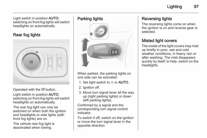
Lighting 97
Light switch in position AUTO:switching on front fog lights will switchheadlights on automatically.
Rear fog lights
Operated with the r button.Light switch in position AUTO:switching on front fog lights will switchheadlights on automatically.The rear fog light can only beswitched on when both the ignitionand headlights or side lights (withfront fog lights) are on.The vehicle rear fog light isdeactivated when towing.
Parking lights
When parked, the parking lights onone side can be activated:1. Set light switch to m or AUTO.2. Ignition off.3. Move turn signal lever all the way
up (right parking lights) or down(left parking lights).
Confirmed by a signal and thecorresponding turn signal controlindicator.To switch it off, switch on the ignitionor move the turn signal lever in theopposite direction.
Reversing lightsThe reversing lights come on whenthe ignition is on and reverse gear isselected.
Misted light coversThe inside of the light covers may mistup briefly in poor, wet and coldweather conditions, in heavy rain orafter washing. The mist disappearsquickly by itself; to help, switch on theheadlights.
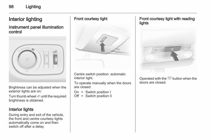
98 Lighting
Interior lightingInstrument panel illuminationcontrol
Brightness can be adjusted when theexterior lights are on:Turn thumb wheel A until the requiredbrightness is obtained.
Interior lightsDuring entry and exit of the vehicle,the front and centre courtesy lightsautomatically come on and thenswitch off after a delay.
Front courtesy light
Centre switch position: automaticinterior light.To operate manually when the doorsare closed:On = Switch position IOff = Switch position 0
Front courtesy light with readinglights
Operated with the c button when thedoors are closed.
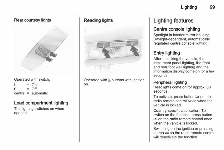
Lighting 99
Rear courtesy lights
Operated with switch.I = On0 = Offcentre = automatic
Load compartment lightingThe lighting switches on whenopened.
Reading lights
Operated with a buttons with ignitionon.
Lighting featuresCentre console lightingSpotlight in interior mirror housing.Daylight-dependent, automaticallyregulated centre console lighting.
Entry lightingAfter unlocking the vehicle, theinstrument panel lighting, the frontand rear foot well lighting and theinformation display come on for a fewseconds.
Peripheral lightingHeadlights come on for approx. 30seconds.To activate, press button q on theradio remote control twice when thevehicle is locked.Country-specific application: Toswitch on the function, press buttonq on the radio remote control oncewhen the vehicle is locked.Switching on the ignition or pressingbutton p on the radio remote controlwill deactivate the function.
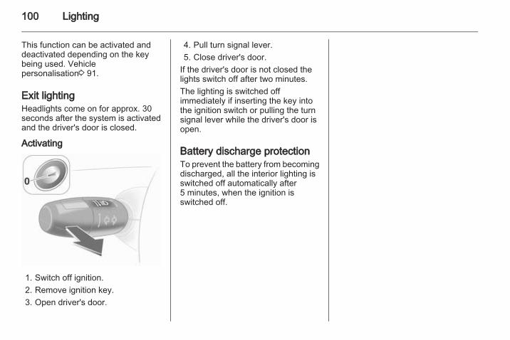
100 Lighting
This function can be activated anddeactivated depending on the keybeing used. Vehiclepersonalisation3 91.
Exit lightingHeadlights come on for approx. 30seconds after the system is activatedand the driver's door is closed.
Activating
1. Switch off ignition.2. Remove ignition key.3. Open driver's door.
4. Pull turn signal lever.5. Close driver's door.
If the driver's door is not closed thelights switch off after two minutes.The lighting is switched offimmediately if inserting the key intothe ignition switch or pulling the turnsignal lever while the driver's door isopen.
Battery discharge protectionTo prevent the battery from becomingdischarged, all the interior lighting isswitched off automatically after5 minutes, when the ignition isswitched off.
Infotainment system 101
Infotainment system
Introduction ................................ 101Radio ......................................... 101Audio players ............................. 102Phone ........................................ 102
IntroductionOperationThe Infotainment system is operatedas described in the Infotainmentsystem manual.
RadioRadio receptionRadio reception may be disrupted bystatic, noise, or distortion due to■ changes in distance from the
transmitter,■ multi-path reception due to
reflection,■ shadowing.
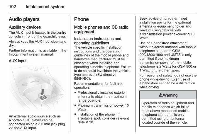
102 Infotainment system
Audio playersAuxiliary devicesThe AUX input is located in the centreconsole in front of the gearshift lever.Always keep the AUX input clean anddry.Further information is available in theInfotainment system manual.
AUX input
An external audio source such asa portable CD player can beconnected using a 3.5 mm jack plugvia the AUX input.
PhoneMobile phones and CB radioequipmentInstallation instructions andoperating guidelinesThe vehicle specific installationinstructions and the operatingguidelines of the mobile phone andhandsfree manufacturer must beobserved when installing andoperating a mobile telephone. Failureto do so could invalidate the vehicletype approval (EU directive95/54/EC).Recommendations for fault-freeoperation:■ Professionally installed exterior
antenna to obtain the maximumrange possible,
■ Maximum transmission power 10Watts,
■ Installation of the phone ina suitable spot, consider relevantNote 3 38.
Seek advice on predeterminedinstallation points for the externalantenna or equipment holder andways of using devices witha transmission power exceeding 10Watts.Use of a handsfree attachmentwithout external antenna with mobiletelephone standards GSM900/1800/1900 and UMTS is onlypermitted if the maximumtransmission power of the mobiletelephone is 2 Watts for GSM 900 or1 Watt for the other types.For reasons of safety, do not use thephone while driving. Even use ofa handsfree set can be a distractionwhile driving.
9 Warning
Operation of radio equipment andmobile telephones which fail tomeet above mentioned mobiletelephone standards is onlypermitted using an antennalocated outside of the vehicle.
Infotainment system 103
Caution
Mobile telephones and radioequipment may lead tomalfunctions in the vehicleelectronics when operated insidethe vehicle with no exteriorantenna, unless the abovementioned regulations areobserved.
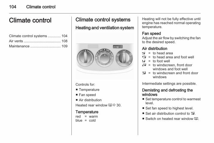
104 Climate control
Climate control
Climate control systems ............. 104Air vents ..................................... 108Maintenance .............................. 109
Climate control systemsHeating and ventilation system
Controls for:■ Temperature■ Fan speed■ Air distributionHeated rear window Ü 3 30.
Temperaturered = warmblue = cold
Heating will not be fully effective untilengine has reached normal operatingtemperature.
Fan speedAdjust the air flow by switching the fanto the desired speed.
Air distributionM = to head areaL = to head area and foot wellK = to foot wellJ = to windscreen, front door
windows and foot welll = to windscreen and front door
windows
Intermediate settings are possible.
Demisting and defrosting thewindows■ Set temperature control to warmest
level.■ Set fan speed to highest level.■ Set air distribution control to l.■ Switch on heated rear window Ü.
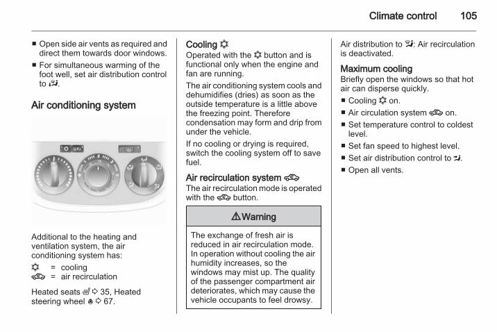
Climate control 105
■ Open side air vents as required anddirect them towards door windows.
■ For simultaneous warming of thefoot well, set air distribution controlto J.
Air conditioning system
Additional to the heating andventilation system, the airconditioning system has:n = cooling4 = air recirculation
Heated seats ß 3 35, Heatedsteering wheel * 3 67.
Cooling nOperated with the n button and isfunctional only when the engine andfan are running.The air conditioning system cools anddehumidifies (dries) as soon as theoutside temperature is a little abovethe freezing point. Thereforecondensation may form and drip fromunder the vehicle.If no cooling or drying is required,switch the cooling system off to savefuel.
Air recirculation system 4The air recirculation mode is operatedwith the 4 button.
9 Warning
The exchange of fresh air isreduced in air recirculation mode.In operation without cooling the airhumidity increases, so thewindows may mist up. The qualityof the passenger compartment airdeteriorates, which may cause thevehicle occupants to feel drowsy.
Air distribution to l: Air recirculationis deactivated.
Maximum coolingBriefly open the windows so that hotair can disperse quickly.■ Cooling n on.■ Air circulation system 4 on.■ Set temperature control to coldest
level.■ Set fan speed to highest level.■ Set air distribution control to M.■ Open all vents.
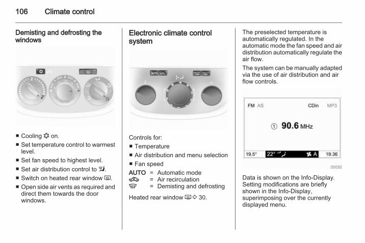
106 Climate control
Demisting and defrosting thewindows
■ Cooling n on.■ Set temperature control to warmest
level.■ Set fan speed to highest level.■ Set air distribution control to l.■ Switch on heated rear window Ü.■ Open side air vents as required and
direct them towards the doorwindows.
Electronic climate controlsystem
Controls for:■ Temperature■ Air distribution and menu selection■ Fan speedAUTO = Automatic mode4 = Air recirculationV = Demisting and defrosting
Heated rear window Ü 3 30.
The preselected temperature isautomatically regulated. In theautomatic mode the fan speed and airdistribution automatically regulate theair flow.The system can be manually adaptedvia the use of air distribution and airflow controls.
Data is shown on the Info-Display.Setting modifications are brieflyshown in the Info-Display,superimposing over the currentlydisplayed menu.
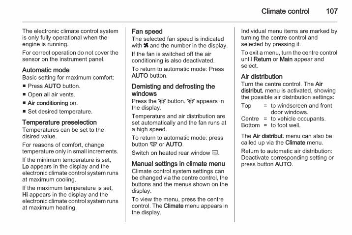
Climate control 107
The electronic climate control systemis only fully operational when theengine is running.For correct operation do not cover thesensor on the instrument panel.
Automatic modeBasic setting for maximum comfort:■ Press AUTO button.■ Open all air vents.■ Air conditioning on.■ Set desired temperature.
Temperature preselectionTemperatures can be set to thedisired value.For reasons of comfort, changetemperature only in small increments.If the minimum temperature is set,Lo appears in the display and theelectronic climate control system runsat maximum cooling.If the maximum temperature is set,Hi appears in the display and theelectronic climate control system runsat maximum heating.
Fan speedThe selected fan speed is indicatedwith x and the number in the display.If the fan is switched off the airconditioning is also deactivated.To return to automatic mode: PressAUTO button.
Demisting and defrosting thewindowsPress the V button. V appears inthe display.Temperature and air distribution areset automatically and the fan runs ata high speed.To return to automatic mode: pressbutton V or AUTO.Switch on heated rear window Ü.
Manual settings in climate menuClimate control system settings canbe changed via the centre control, thebuttons and the menus shown on thedisplay.To view the menu, press the centrecontrol. The Climate menu appears inthe display.
Individual menu items are marked byturning the centre control andselected by pressing it.To exit a menu, turn the centre controluntil Return or Main appear andselect.
Air distributionTurn the centre control. The Airdistribut. menu is activated, showingthe possible air distribution settings:Top = to windscreen and front
door windows.Centre = to vehicle occupants.Bottom = to foot well.
The Air distribut. menu can also becalled up via the Climate menu.Return to automatic air distribution:Deactivate corresponding setting orpress button AUTO.
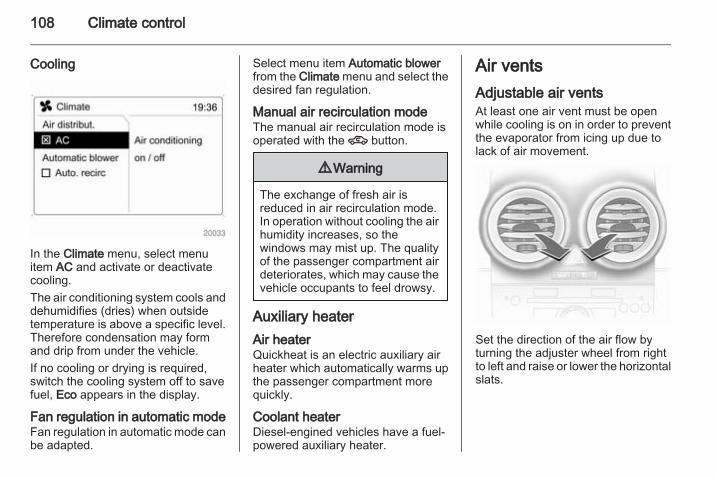
108 Climate control
Cooling
In the Climate menu, select menuitem AC and activate or deactivatecooling.The air conditioning system cools anddehumidifies (dries) when outsidetemperature is above a specific level.Therefore condensation may formand drip from under the vehicle.If no cooling or drying is required,switch the cooling system off to savefuel, Eco appears in the display.
Fan regulation in automatic modeFan regulation in automatic mode canbe adapted.
Select menu item Automatic blowerfrom the Climate menu and select thedesired fan regulation.
Manual air recirculation modeThe manual air recirculation mode isoperated with the 4 button.
9 Warning
The exchange of fresh air isreduced in air recirculation mode.In operation without cooling the airhumidity increases, so thewindows may mist up. The qualityof the passenger compartment airdeteriorates, which may cause thevehicle occupants to feel drowsy.
Auxiliary heaterAir heaterQuickheat is an electric auxiliary airheater which automatically warms upthe passenger compartment morequickly.
Coolant heaterDiesel-engined vehicles have a fuel-powered auxiliary heater.
Air ventsAdjustable air ventsAt least one air vent must be openwhile cooling is on in order to preventthe evaporator from icing up due tolack of air movement.
Set the direction of the air flow byturning the adjuster wheel from rightto left and raise or lower the horizontalslats.
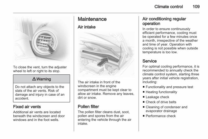
Climate control 109
To close the vent, turn the adjusterwheel to left or right to its stop.
9 Warning
Do not attach any objects to theslats of the air vents. Risk ofdamage and injury in case of anaccident.
Fixed air ventsAdditional air vents are locatedbeneath the windscreen and doorwindows and in the foot wells.
MaintenanceAir intake
The air intake in front of thewindscreen in the enginecompartment must be kept clear toallow air intake. Remove any leaves,dirt or snow.
Pollen filterThe pollen filter cleans dust, soot,pollen and spores from the airentering the vehicle through the airintake.
Air conditioning regularoperationIn order to ensure continuouslyefficient performance, cooling mustbe operated for a few minutes oncea month, irrespective of the weatherand time of year. Operation withcooling is not possible when outsidetemperature is too low.
ServiceFor optimal cooling performance, it isrecommended to annually check theclimate control system, starting threeyears after initial vehicle registration,including:■ Functionality and pressure test■ Heating functionality■ Leakage check■ Check of drive belts■ Cleaning of condenser and
evaporator drainage■ Performance check
110 Driving and operating
Driving andoperating
Driving hints ............................... 110Starting and operating ............... 110Engine exhaust .......................... 112Automatic transmission .............. 114Manual transmission .................. 117Manual transmissionautomated .................................. 118Brakes ........................................ 122Ride control systems ................. 123Cruise control ............................. 124Object detection systems ........... 125Fuel ............................................ 126Towing ....................................... 129
Driving hintsControl of the vehicleNever coast with engine notrunningMany systems will not function in thissituation (e.g. brake servo unit, powersteering). Driving in this manner isa danger to yourself and others.
PedalsTo ensure the pedal travel isuninhibited, there must be no mats inthe area of the pedals.
Starting and operatingNew vehicle running-inDo not brake unnecessarily hard forthe first few journeys.During the first drive, smoke mayoccur because of wax and oilevaporating off the exhaust system.Park the vehicle in the open fora while after the first drive and avoidinhaling the fumes.During the running-in period fuel andengine oil consumption may behigher and the cleaning process ofthe diesel particle filter may takeplace more often. Diesel particle filter3 112.
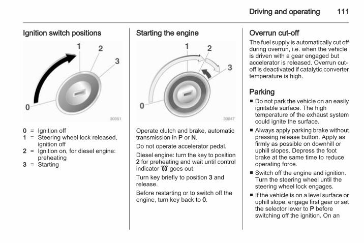
Driving and operating 111
Ignition switch positions
0 = Ignition off1 = Steering wheel lock released,
ignition off2 = Ignition on, for diesel engine:
preheating3 = Starting
Starting the engine
Operate clutch and brake, automatictransmission in P or N.Do not operate accelerator pedal.Diesel engine: turn the key to position2 for preheating and wait until controlindicator ! goes out.Turn key briefly to position 3 andrelease.Before restarting or to switch off theengine, turn key back to 0.
Overrun cut-offThe fuel supply is automatically cut offduring overrun, i.e. when the vehicleis driven with a gear engaged butaccelerator is released. Overrun cut-off is deactivated if catalytic convertertemperature is high.
Parking■ Do not park the vehicle on an easily
ignitable surface. The hightemperature of the exhaust systemcould ignite the surface.
■ Always apply parking brake withoutpressing release button. Apply asfirmly as possible on downhill oruphill slopes. Depress the footbrake at the same time to reduceoperating force.
■ Switch off the engine and ignition.Turn the steering wheel until thesteering wheel lock engages.
■ If the vehicle is on a level surface oruphill slope, engage first gear or setthe selector lever to P beforeswitching off the ignition. On an
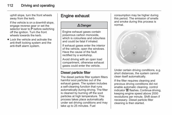
112 Driving and operating
uphill slope, turn the front wheelsaway from the kerb.If the vehicle is on a downhill slope,engage reverse gear or set theselector lever to P before switchingoff the ignition. Turn the frontwheels towards the kerb.
■ Lock the vehicle and activate theanti-theft locking system and theanti-theft alarm system.
Engine exhaust
9 Danger
Engine exhaust gases containpoisonous carbon monoxide,which is colourless and odourlessand could be fatal if inhaled.If exhaust gases enter the interiorof the vehicle, open the windows.Have the cause of the faultrectified by a workshop.Avoid driving with an open loadcompartment, otherwise exhaustgases could enter the vehicle.
Diesel particle filterThe diesel particle filter system filtersharmful soot particles out of theexhaust gases. The system includesa self-cleaning function that runsautomatically during driving. The filteris cleaned by burning off the sootparticles at high temperature. Thisprocess takes place automaticallyunder set driving conditions and maytake up to 25 minutes. Fuel
consumption may be higher duringthis period. The emission of smellsand smoke during this process isnormal.
Under certain driving conditions, e.g.short distances, the system cannotclean itself automatically.If the filter requires cleaning andprevious driving conditions did notenable automatic cleaning, controlindicator ! flashes. Continue driving,keeping engine speed above 2000revolutions per minute. Shift down ifnecessary. Diesel particle filtercleaning is then started.
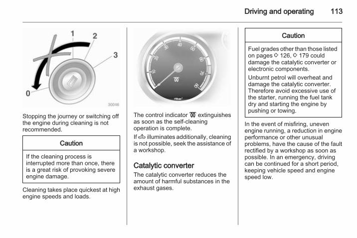
Driving and operating 113
Stopping the journey or switching offthe engine during cleaning is notrecommended.
Caution
If the cleaning process isinterrupted more than once, thereis a great risk of provoking severeengine damage.
Cleaning takes place quickest at highengine speeds and loads.
The control indicator ! extinguishesas soon as the self-cleaningoperation is complete.If A illuminates additionally, cleaningis not possible, seek the assistance ofa workshop.
Catalytic converterThe catalytic converter reduces theamount of harmful substances in theexhaust gases.
Caution
Fuel grades other than those listedon pages 3 126, 3 179 coulddamage the catalytic converter orelectronic components.Unburnt petrol will overheat anddamage the catalytic converter.Therefore avoid excessive use ofthe starter, running the fuel tankdry and starting the engine bypushing or towing.
In the event of misfiring, unevenengine running, a reduction in engineperformance or other unusualproblems, have the cause of the faultrectified by a workshop as soon aspossible. In an emergency, drivingcan be continued for a short period,keeping vehicle speed and enginespeed low.
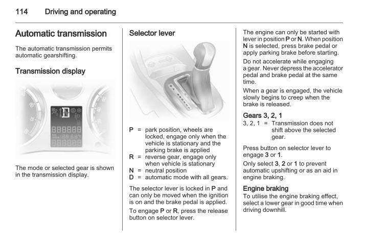
114 Driving and operating
Automatic transmissionThe automatic transmission permitsautomatic gearshifting.
Transmission display
The mode or selected gear is shownin the transmission display.
Selector lever
P = park position, wheels arelocked, engage only when thevehicle is stationary and theparking brake is applied
R = reverse gear, engage onlywhen vehicle is stationary
N = neutral positionD = automatic mode with all gears.
The selector lever is locked in P andcan only be moved when the ignitionis on and the brake pedal is applied.To engage P or R, press the releasebutton on selector lever.
The engine can only be started withlever in position P or N. When positionN is selected, press brake pedal orapply parking brake before starting.Do not accelerate while engaginga gear. Never depress the acceleratorpedal and brake pedal at the sametime.When a gear is engaged, the vehicleslowly begins to creep when thebrake is released.
Gears 3, 2, 13, 2, 1 = Transmission does not
shift above the selectedgear.
Press button on selector lever toengage 3 or 1.Only select 3, 2 or 1 to preventautomatic upshifting or as an aid inengine braking.
Engine brakingTo utilise the engine braking effect,select a lower gear in good time whendriving downhill.
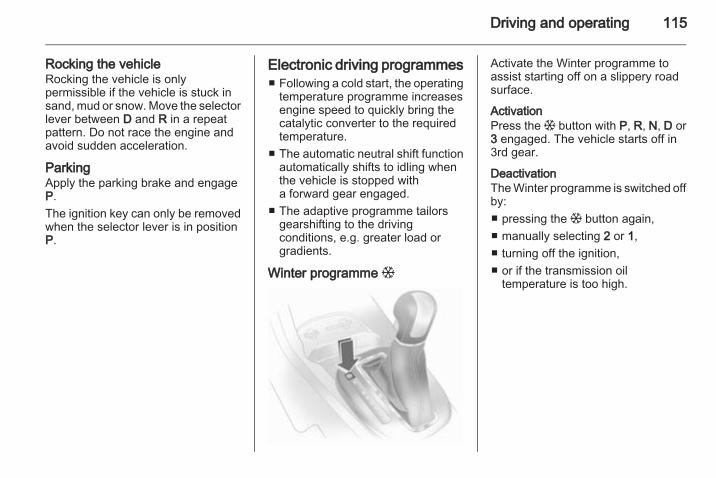
Driving and operating 115
Rocking the vehicleRocking the vehicle is onlypermissible if the vehicle is stuck insand, mud or snow. Move the selectorlever between D and R in a repeatpattern. Do not race the engine andavoid sudden acceleration.
ParkingApply the parking brake and engageP.The ignition key can only be removedwhen the selector lever is in positionP.
Electronic driving programmes■ Following a cold start, the operating
temperature programme increasesengine speed to quickly bring thecatalytic converter to the requiredtemperature.
■ The automatic neutral shift functionautomatically shifts to idling whenthe vehicle is stopped witha forward gear engaged.
■ The adaptive programme tailorsgearshifting to the drivingconditions, e.g. greater load orgradients.
Winter programme T
Activate the Winter programme toassist starting off on a slippery roadsurface.
ActivationPress the T button with P, R, N, D or3 engaged. The vehicle starts off in3rd gear.
DeactivationThe Winter programme is switched offby:■ pressing the T button again,■ manually selecting 2 or 1,■ turning off the ignition,■ or if the transmission oil
temperature is too high.
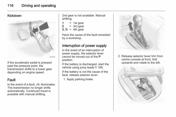
116 Driving and operating
Kickdown
If the accelerator pedal is pressedpast the pressure point, thetransmission shifts to a lower geardepending on engine speed.
FaultIn the event of a fault, A illuminates.The transmission no longer shiftsautomatically. Continued travel ispossible with manual shifting.
2nd gear is not available. Manualshifting:1 = 1st gear2 = 3rd gear3, D = 4th gear
Have the cause of the fault remediedby a workshop.
Interruption of power supplyIn the event of an interruption ofpower supply, the selector levercannot be moved out of the Pposition.If the battery is discharged, start thevehicle using jump leads 3 166.If the battery is not the cause of thefault, release selector lever:1. Apply parking brake.
2. Release selector lever trim fromcentre console at front, foldupwards and rotate to the left.
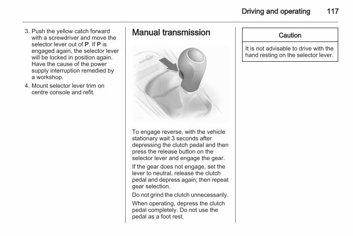
Driving and operating 117
3. Push the yellow catch forwardwith a screwdriver and move theselector lever out of P. If P isengaged again, the selector leverwill be locked in position again.Have the cause of the powersupply interruption remedied bya workshop.
4. Mount selector lever trim oncentre console and refit.
Manual transmission
To engage reverse, with the vehiclestationary wait 3 seconds afterdepressing the clutch pedal and thenpress the release button on theselector lever and engage the gear.If the gear does not engage, set thelever to neutral, release the clutchpedal and depress again; then repeatgear selection.Do not grind the clutch unnecessarily.When operating, depress the clutchpedal completely. Do not use thepedal as a foot rest.
Caution
It is not advisable to drive with thehand resting on the selector lever.
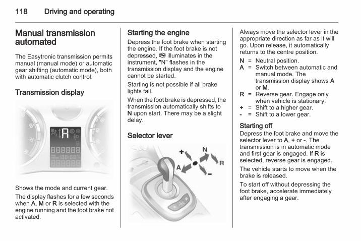
118 Driving and operating
Manual transmissionautomatedThe Easytronic transmission permitsmanual (manual mode) or automaticgear shifting (automatic mode), bothwith automatic clutch control.
Transmission display
Shows the mode and current gear.The display flashes for a few secondswhen A, M or R is selected with theengine running and the foot brake notactivated.
Starting the engineDepress the foot brake when startingthe engine. If the foot brake is notdepressed, j illuminates in theinstrument, "N" flashes in thetransmission display and the enginecannot be started.Starting is not possible if all brakelights fail.When the foot brake is depressed, thetransmission automatically shifts toN upon start. There may be a slightdelay.
Selector lever
Always move the selector lever in theappropriate direction as far as it willgo. Upon release, it automaticallyreturns to the centre position.N = Neutral position.A = Switch between automatic and
manual mode. Thetransmission display shows Aor M.
R = Reverse gear. Engage onlywhen vehicle is stationary.
+ = Shift to a higher gear.- = Shift to a lower gear.
Starting offDepress the foot brake and move theselector lever to A, + or -. Thetransmission is in automatic modeand first gear is engaged. If R isselected, reverse gear is engaged.The vehicle starts to move when thebrake is released.To start off without depressing thefoot brake, accelerate immediatelyafter engaging a gear.
Driving and operating 119
If neither the accelerator nor thebrake pedal are depressed, no gearis engaged and A or R flashes fora brief time in the display.
Stopping the vehicleIn A, first gear is engaged and theclutch is released when the vehicle isstopped. In R, reverse gear remainsengaged.
Engine brakingAutomatic modeWhen driving downhill, the manualtransmission automated does notshift into higher gears until a fairlyhigh engine speed has been reached.It shifts down in good time whenbraking.
Manual modeTo utilise the engine braking effect,select a lower gear in good time whendriving downhill.
Rocking the vehicleRocking the vehicle is onlypermissible if the vehicle is stuck insand, mud or snow. Move the selectorlever between R and A (or + or -) ina repeat pattern. Do not race theengine and avoid suddenacceleration.
ParkingApply the hand brake. The mostrecently engaged gear (seetransmission display) remainsengaged. With N, no gear is engaged.When the ignition is switched off thetransmission no longer responds tomovement of the selector lever.
Manual modeIf a higher gear is selected when theengine speed is too low, or a lowergear when the speed is too high, theshift is not executed. This preventsthe engine from running at too low ortoo high an engine speed.If engine speed is too low, thetransmission automatically shifts toa lower gear.
If engine speed is too high, thetransmission only switches to a highergear via kickdown.When + or - is selected in automaticmode, the transmission switches tomanual mode and shifts accordingly.
Electronic driving programmes■ Following a cold start, the operating
temperature programme increasesengine speed to quickly bring thecatalytic converter to the requiredtemperature.
■ The adaptive programme tailorsgearshifting to the drivingconditions, e.g. greater load orgradients.
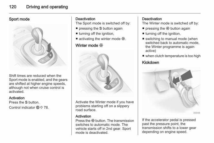
120 Driving and operating
Sport mode
Shift times are reduced when theSport mode is enabled, and the gearsare shifted at higher engine speeds,although not when cruise control isactivated.
ActivationPress the S button.Control indicator 1 3 78.
DeactivationThe Sport mode is switched off by:■ pressing the S button again■ turning off the ignition,■ activating the winter mode T.
Winter mode T
Activate the Winter mode if you haveproblems starting off on a slipperyroad surface.
ActivationPress the T button. The transmissionswitches to automatic mode. Thevehicle starts off in 2nd gear. Sportmode is deactivated.
DeactivationThe Winter mode is switched off by:■ pressing the T button again■ turning off the ignition,■ switching to manual mode (when
switched back to automatic mode,the Winter programme is againactive)
■ when clutch temperature is too high
Kickdown
If the accelerator pedal is pressedpast the pressure point, thetransmission shifts to a lower geardepending on engine speed.
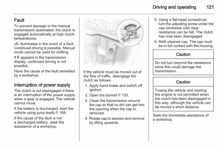
Driving and operating 121
FaultTo prevent damage to the manualtransmission automated, the clutch isengaged automatically at high clutchtemperatures.A illuminates in the event of a fault.Continued driving is possible. Manualmode cannot be used for shifting.If F appears in the transmissiondisplay, continued driving is notpossible.Have the cause of the fault remediedby a workshop.
Interruption of power supplyThe clutch is not disengaged if thereis an interruption of the power supplywhen a gear is engaged. The vehiclecannot move.If the battery is discharged, start thevehicle using jump leads 3 166.If the cause of the fault is nota discharged battery, seek theassistance of a workshop.
If the vehicle must be moved out ofthe flow of traffic, disengage theclutch as follows:1. Apply hand brake and switch off
ignition.2. Open the bonnet 3 135.3. Clean the transmission around
the cap so that no dirt can get intothe opening when the cap isremoved.
4. Rotate cap to slacken and removeby lifting upwards.
5. Using a flat-head screwdriver,turn the adjusting screw under thecap clockwise until clearresistance can be felt. The clutchhas now been disengaged.
6. Refit cleaned cap. The cap mustbe in full contact with the housing.
Caution
Do not turn beyond the resistancesince this could damage thetransmission.
Caution
Towing the vehicle and startingthe engine is not permitted whenthe clutch has been disengaged inthis way, although the vehicle canbe moved a short distance.
Seek the immediate assistance ofa workshop.
122 Driving and operating
BrakesThe brake system comprises twoindependent brake circuits.If a brake circuit fails, the vehicle canstill be braked using the other brakecircuit. However, braking effect isachieved only when you depress thebrake pedal firmly. You need to useconsiderably more force for this. Thebraking distance is extended. Seekthe assistance of a workshop beforecontinuing your journey.When the engine is not running, thesupport of the brake servo unitdisappears once the brake pedal hasbeen depressed once or twice.Braking effect is not reduced, butbraking requires significantly greaterforce. It is especially important to bearthis in mind when being towed.Control indicator R 3 77.
Antilock brake systemAntilock brake system (ABS)prevents the wheels from locking.
ABS starts to regulate brake pressureas soon as a wheel shows a tendencyto lock. The vehicle remainssteerable, even during hard braking.ABS control is made apparent thougha pulse in the brake pedal and thenoise of the regulation process.For optimum braking, keep the brakepedal fully depressed throughout thebraking process, despite the fact thatthe pedal is pulsating. Do not reducethe pressure on the pedal.Control indicator u 3 77.
Adaptive brake lightDuring full braking, all three brakelamps flash for the duration of ABScontrol.
Fault
9 Warning
If there is a fault in the ABS, thewheels may be liable to lock dueto braking that is heavier thannormal. The advantages of ABSare no longer available. Duringhard braking, the vehicle can nolonger be steered and mayswerve.
Have the cause of the fault remediedby a workshop.
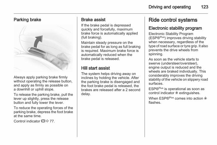
Driving and operating 123
Parking brake
Always apply parking brake firmlywithout operating the release button,and apply as firmly as possible ona downhill or uphill slope.To release the parking brake, pull thelever up slightly, press the releasebutton and fully lower the lever.To reduce the operating forces of theparking brake, depress the foot brakeat the same time.Control indicator R 3 77.
Brake assistIf the brake pedal is depressedquickly and forcefully, maximumbrake force is automatically applied(full braking).Maintain steady pressure on thebrake pedal for as long as full brakingis required. Maximum brake force isautomatically reduced when thebrake pedal is released.
Hill start assistThe system helps driving away oninclines by holding the vehicle. Afterthe parking brake is disengaged andthe foot brake pedal is released, thebrakes are released after a 2 seconddelay.
Ride control systemsElectronic stability programElectronic Stability Program(ESP®Plus) improves driving stabilitywhen necessary, regardless of thetype of road surface or tyre grip. It alsoprevents the drive wheels fromspinning.As soon as the vehicle starts toswerve (understeer/oversteer),engine output is reduced and thewheels are braked individually. Thisconsiderably improves the drivingstability of the vehicle on slippery roadsurfaces.ESP®Plus is operational as soon ascontrol indicator v extinguishes.When ESP®Plus comes into action vflashes.
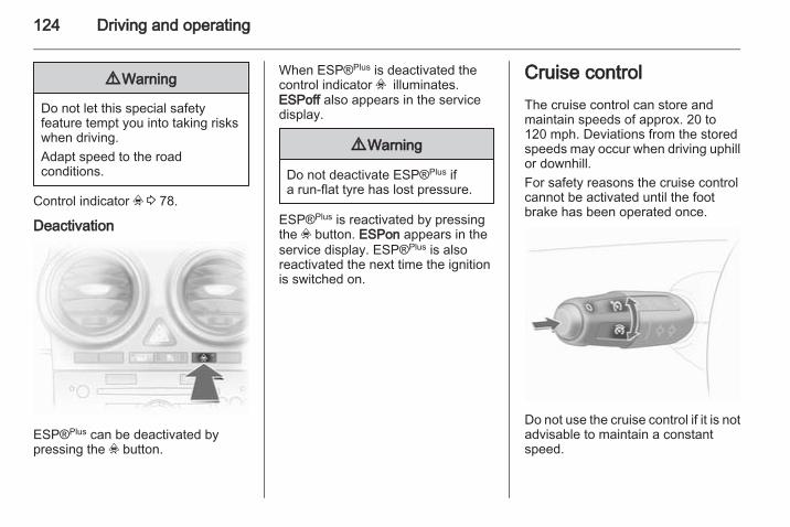
124 Driving and operating
9 Warning
Do not let this special safetyfeature tempt you into taking riskswhen driving.Adapt speed to the roadconditions.
Control indicator v 3 78.
Deactivation
ESP®Plus can be deactivated bypressing the v button.
When ESP®Plus is deactivated thecontrol indicator v illuminates.ESPoff also appears in the servicedisplay.
9 Warning
Do not deactivate ESP®Plus ifa run-flat tyre has lost pressure.
ESP®Plus is reactivated by pressingthe v button. ESPon appears in theservice display. ESP®Plus is alsoreactivated the next time the ignitionis switched on.
Cruise controlThe cruise control can store andmaintain speeds of approx. 20 to120 mph. Deviations from the storedspeeds may occur when driving uphillor downhill.For safety reasons the cruise controlcannot be activated until the footbrake has been operated once.
Do not use the cruise control if it is notadvisable to maintain a constantspeed.
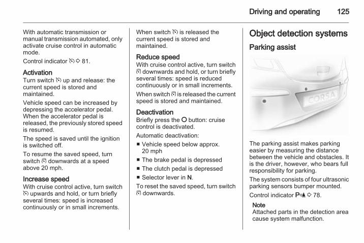
Driving and operating 125
With automatic transmission ormanual transmission automated, onlyactivate cruise control in automaticmode.Control indicator m 3 81.
ActivationTurn switch m up and release: thecurrent speed is stored andmaintained.Vehicle speed can be increased bydepressing the accelerator pedal.When the accelerator pedal isreleased, the previously stored speedis resumed.The speed is saved until the ignitionis switched off.To resume the saved speed, turnswitch g downwards at a speedabove 20 mph.
Increase speedWith cruise control active, turn switchm upwards and hold, or turn brieflyseveral times: speed is increasedcontinuously or in small increments.
When switch m is released thecurrent speed is stored andmaintained.
Reduce speedWith cruise control active, turn switchg downwards and hold, or turn brieflyseveral times: speed is reducedcontinuously or in small increments.When switch g is released the currentspeed is stored and maintained.
DeactivationBriefly press the § button: cruisecontrol is deactivated.Automatic deactivation:■ Vehicle speed below approx.
20 mph■ The brake pedal is depressed■ The clutch pedal is depressed■ Selector lever in N.To reset the saved speed, turn switchg downwards.
Object detection systemsParking assist
The parking assist makes parkingeasier by measuring the distancebetween the vehicle and obstacles. Itis the driver, however, who bears fullresponsibility for parking.The system consists of four ultrasonicparking sensors bumper mounted.Control indicator r 3 78.NoteAttached parts in the detection areacause system malfunction.
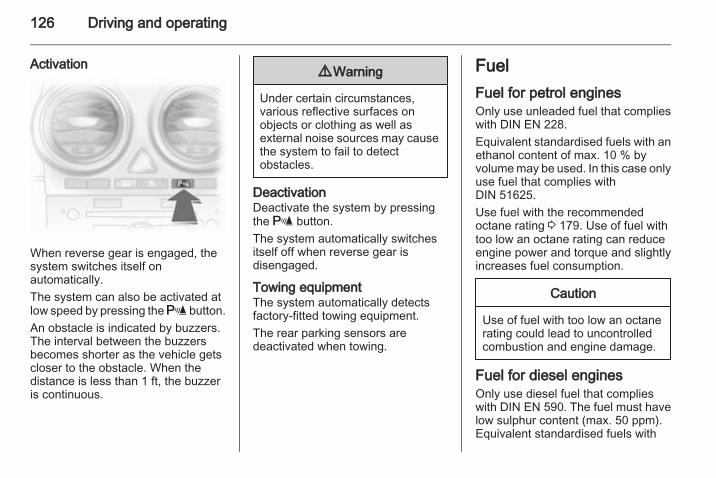
126 Driving and operating
Activation
When reverse gear is engaged, thesystem switches itself onautomatically.The system can also be activated atlow speed by pressing the r button.An obstacle is indicated by buzzers.The interval between the buzzersbecomes shorter as the vehicle getscloser to the obstacle. When thedistance is less than 1 ft, the buzzeris continuous.
9 Warning
Under certain circumstances,various reflective surfaces onobjects or clothing as well asexternal noise sources may causethe system to fail to detectobstacles.
DeactivationDeactivate the system by pressingthe r button.The system automatically switchesitself off when reverse gear isdisengaged.
Towing equipmentThe system automatically detectsfactory-fitted towing equipment.The rear parking sensors aredeactivated when towing.
FuelFuel for petrol enginesOnly use unleaded fuel that complieswith DIN EN 228.Equivalent standardised fuels with anethanol content of max. 10 % byvolume may be used. In this case onlyuse fuel that complies withDIN 51625.Use fuel with the recommendedoctane rating 3 179. Use of fuel withtoo low an octane rating can reduceengine power and torque and slightlyincreases fuel consumption.
Caution
Use of fuel with too low an octanerating could lead to uncontrolledcombustion and engine damage.
Fuel for diesel enginesOnly use diesel fuel that complieswith DIN EN 590. The fuel must havelow sulphur content (max. 50 ppm).Equivalent standardised fuels with
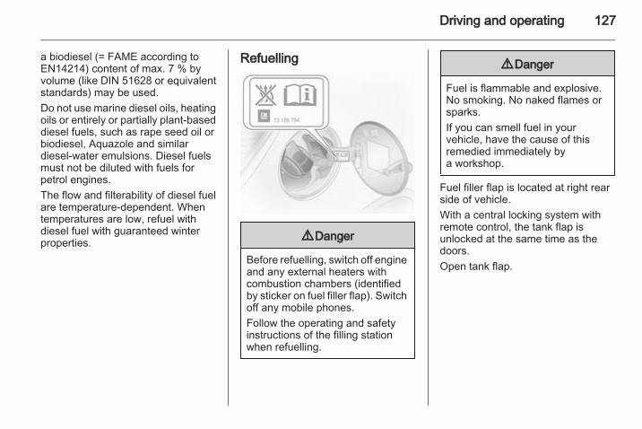
Driving and operating 127
a biodiesel (= FAME according toEN14214) content of max. 7 % byvolume (like DIN 51628 or equivalentstandards) may be used.Do not use marine diesel oils, heatingoils or entirely or partially plant-baseddiesel fuels, such as rape seed oil orbiodiesel, Aquazole and similardiesel-water emulsions. Diesel fuelsmust not be diluted with fuels forpetrol engines.The flow and filterability of diesel fuelare temperature-dependent. Whentemperatures are low, refuel withdiesel fuel with guaranteed winterproperties.
Refuelling
9 Danger
Before refuelling, switch off engineand any external heaters withcombustion chambers (identifiedby sticker on fuel filler flap). Switchoff any mobile phones.Follow the operating and safetyinstructions of the filling stationwhen refuelling.
9 Danger
Fuel is flammable and explosive.No smoking. No naked flames orsparks.If you can smell fuel in yourvehicle, have the cause of thisremedied immediately bya workshop.
Fuel filler flap is located at right rearside of vehicle.With a central locking system withremote control, the tank flap isunlocked at the same time as thedoors.Open tank flap.
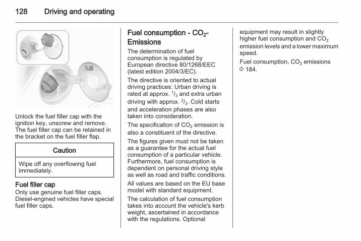
128 Driving and operating
Unlock the fuel filler cap with theignition key, unscrew and remove.The fuel filler cap can be retained inthe bracket on the fuel filler flap.
Caution
Wipe off any overflowing fuelimmediately.
Fuel filler capOnly use genuine fuel filler caps.Diesel-engined vehicles have specialfuel filler caps.
Fuel consumption - CO2-EmissionsThe determination of fuelconsumption is regulated byEuropean directive 80/1268/EEC(latest edition 2004/3/EC).The directive is oriented to actualdriving practices: Urban driving israted at approx. 1/3 and extra urbandriving with approx. 2/3. Cold startsand acceleration phases are alsotaken into consideration.The specification of CO2 emission isalso a constituent of the directive.The figures given must not be takenas a guarantee for the actual fuelconsumption of a particular vehicle.Furthermore, fuel consumption isdependent on personal driving styleas well as road and traffic conditions.All values are based on the EU basemodel with standard equipment.The calculation of fuel consumptiontakes into account the vehicle's kerbweight, ascertained in accordancewith the regulations. Optional
equipment may result in slightlyhigher fuel consumption and CO2emission levels and a lower maximumspeed.Fuel consumption, CO2 emissions3 184.
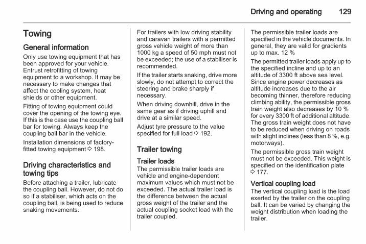
Driving and operating 129
TowingGeneral informationOnly use towing equipment that hasbeen approved for your vehicle.Entrust retrofitting of towingequipment to a workshop. It may benecessary to make changes thataffect the cooling system, heatshields or other equipment.Fitting of towing equipment couldcover the opening of the towing eye.If this is the case use the coupling ballbar for towing. Always keep thecoupling ball bar in the vehicle.Installation dimensions of factory-fitted towing equipment 3 198.
Driving characteristics andtowing tipsBefore attaching a trailer, lubricatethe coupling ball. However, do not doso if a stabiliser, which acts on thecoupling ball, is being used to reducesnaking movements.
For trailers with low driving stabilityand caravan trailers with a permittedgross vehicle weight of more than1000 kg a speed of 50 mph must notbe exceeded; the use of a stabiliser isrecommended.If the trailer starts snaking, drive moreslowly, do not attempt to correct thesteering and brake sharply ifnecessary.When driving downhill, drive in thesame gear as if driving uphill anddrive at a similar speed.Adjust tyre pressure to the valuespecified for full load 3 192.
Trailer towingTrailer loadsThe permissible trailer loads arevehicle and engine-dependentmaximum values which must not beexceeded. The actual trailer load isthe difference between the actualgross weight of the trailer and theactual coupling socket load with thetrailer coupled.
The permissible trailer loads arespecified in the vehicle documents. Ingeneral, they are valid for gradientsup to max. 12 %The permitted trailer loads apply up tothe specified incline and up to analtitude of 3300 ft above sea level.Since engine power decreases asaltitude increases due to the airbecoming thinner, therefore reducingclimbing ability, the permissible grosstrain weight also decreases by 10 %for every 3300 ft of additional altitude.The gross train weight does not haveto be reduced when driving on roadswith slight inclines (less than 8 %, e.g.motorways).The permissible gross train weightmust not be exceeded. This weight isspecified on the identification plate3 177.
Vertical coupling loadThe vertical coupling load is the loadexerted by the trailer on the couplingball. It can be varied by changing theweight distribution when loading thetrailer.
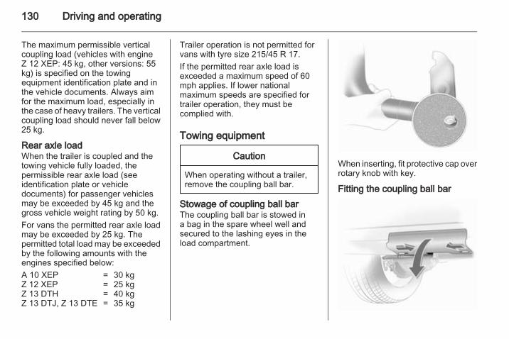
130 Driving and operating
The maximum permissible verticalcoupling load (vehicles with engineZ 12 XEP: 45 kg, other versions: 55kg) is specified on the towingequipment identification plate and inthe vehicle documents. Always aimfor the maximum load, especially inthe case of heavy trailers. The verticalcoupling load should never fall below25 kg.
Rear axle loadWhen the trailer is coupled and thetowing vehicle fully loaded, thepermissible rear axle load (seeidentification plate or vehicledocuments) for passenger vehiclesmay be exceeded by 45 kg and thegross vehicle weight rating by 50 kg.For vans the permitted rear axle loadmay be exceeded by 25 kg. Thepermitted total load may be exceededby the following amounts with theengines specified below:A 10 XEP = 30 kgZ 12 XEP = 25 kgZ 13 DTH = 40 kgZ 13 DTJ, Z 13 DTE = 35 kg
Trailer operation is not permitted forvans with tyre size 215/45 R 17.If the permitted rear axle load isexceeded a maximum speed of 60mph applies. If lower nationalmaximum speeds are specified fortrailer operation, they must becomplied with.
Towing equipment
Caution
When operating without a trailer,remove the coupling ball bar.
Stowage of coupling ball barThe coupling ball bar is stowed ina bag in the spare wheel well andsecured to the lashing eyes in theload compartment.
When inserting, fit protective cap overrotary knob with key.
Fitting the coupling ball bar
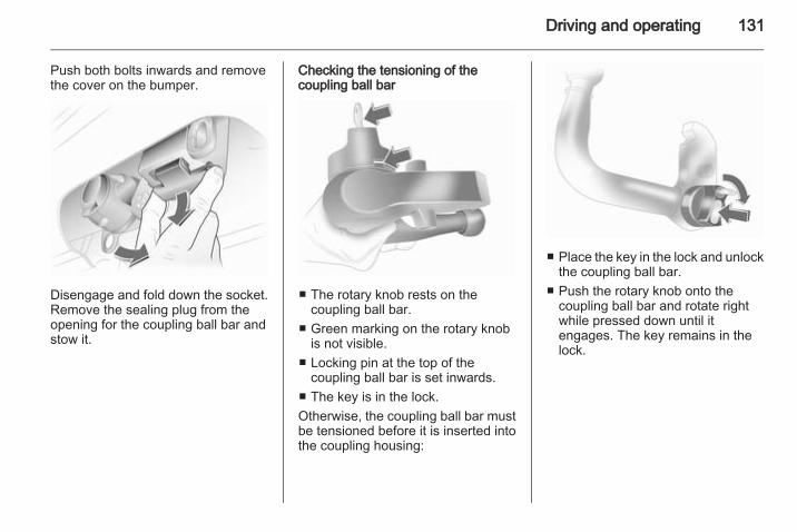
Driving and operating 131
Push both bolts inwards and removethe cover on the bumper.
Disengage and fold down the socket.Remove the sealing plug from theopening for the coupling ball bar andstow it.
Checking the tensioning of thecoupling ball bar
■ The rotary knob rests on thecoupling ball bar.
■ Green marking on the rotary knobis not visible.
■ Locking pin at the top of thecoupling ball bar is set inwards.
■ The key is in the lock.Otherwise, the coupling ball bar mustbe tensioned before it is inserted intothe coupling housing:
■ Place the key in the lock and unlockthe coupling ball bar.
■ Push the rotary knob onto thecoupling ball bar and rotate rightwhile pressed down until itengages. The key remains in thelock.
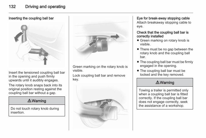
132 Driving and operating
Inserting the coupling ball bar
Insert the tensioned coupling ball barin the opening and push firmlyupwards until it audibly engages.The rotary knob snaps back into itsoriginal position resting against thecoupling ball bar without a gap.
9 Warning
Do not touch rotary knob duringinsertion.
Green marking on the rotary knob isvisible.Lock coupling ball bar and removekey.
Eye for break-away stopping cableAttach breakaway stopping cable toeye.
Check that the coupling ball bar iscorrectly installed■ Green marking on rotary knob is
visible.■ There must be no gap between the
rotary knob and the coupling ballbar.
■ The coupling ball bar must be firmlyengaged in the opening.
■ The coupling ball bar must belocked and the key removed.
9 Warning
Towing a trailer is permitted onlywhen a coupling ball bar is fittedcorrectly. If the coupling ball bardoes not engage correctly, seekthe assistance of a workshop.
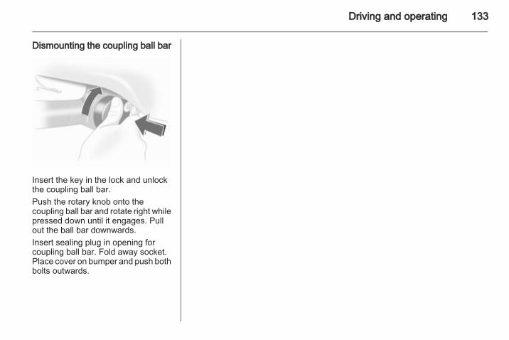
Driving and operating 133
Dismounting the coupling ball bar
Insert the key in the lock and unlockthe coupling ball bar.Push the rotary knob onto thecoupling ball bar and rotate right whilepressed down until it engages. Pullout the ball bar downwards.Insert sealing plug in opening forcoupling ball bar. Fold away socket.Place cover on bumper and push bothbolts outwards.
134 Vehicle care
Vehicle care
General Information ................... 134Vehicle checks ........................... 135Bulb replacement ....................... 140Electrical system ........................ 152Vehicle tools .............................. 156Wheels and tyres ....................... 157Jump starting ............................. 166Towing ....................................... 168Appearance care ....................... 170
General InformationAccessories and vehiclemodificationsWe recommend to use genuine partsand accessories and factoryapproved parts specific for yourvehicle type. We cannot assess orguarantee reliability of other products- even if they have a regulatory orotherwise granted approval.Do not make any modifications to theelectrical system, e.g. changes ofelectronic control units (chip tuning).
Vehicle storageStorage for a long period of timeFollowing must be done if the vehicleshould be stored for several months:■ Wash and wax the vehicle.■ Have the wax in the engine
compartment and underbodychecked.
■ Clean and preserve rubber seals.■ Change engine oil.
■ Drain washer fluid reservoir.■ Check coolant antifreeze and
corrosion protection.■ Adjust tyre pressure to the value
specified for full load.■ Park vehicle in dry, well ventilated
place. Engage first or reverse gearor set selector lever to P. Preventthe vehicle from rolling.
■ Do not apply hand brake.■ Open bonnet, close all doors and
lock the vehicle.■ Disconnect the clamp from the
negative terminal of the vehiclebattery. Beware that all systems arenot functional, e.g. anti-theft alarmsystem.
Putting back into operationFollowing must be done if the vehicleis putting back into operation:■ Connect the clamp to the negative
terminal of the vehicle battery.Activate the electronics of thepower windows.
■ Check tyre pressure.■ Fill up the washer fluid reservoir.
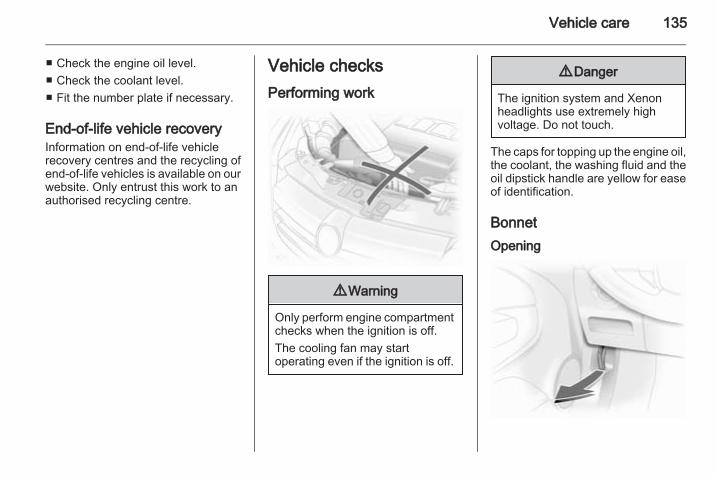
Vehicle care 135
■ Check the engine oil level.■ Check the coolant level.■ Fit the number plate if necessary.
End-of-life vehicle recoveryInformation on end-of-life vehiclerecovery centres and the recycling ofend-of-life vehicles is available on ourwebsite. Only entrust this work to anauthorised recycling centre.
Vehicle checksPerforming work
9 Warning
Only perform engine compartmentchecks when the ignition is off.The cooling fan may startoperating even if the ignition is off.
9 Danger
The ignition system and Xenonheadlights use extremely highvoltage. Do not touch.
The caps for topping up the engine oil,the coolant, the washing fluid and theoil dipstick handle are yellow for easeof identification.
BonnetOpening
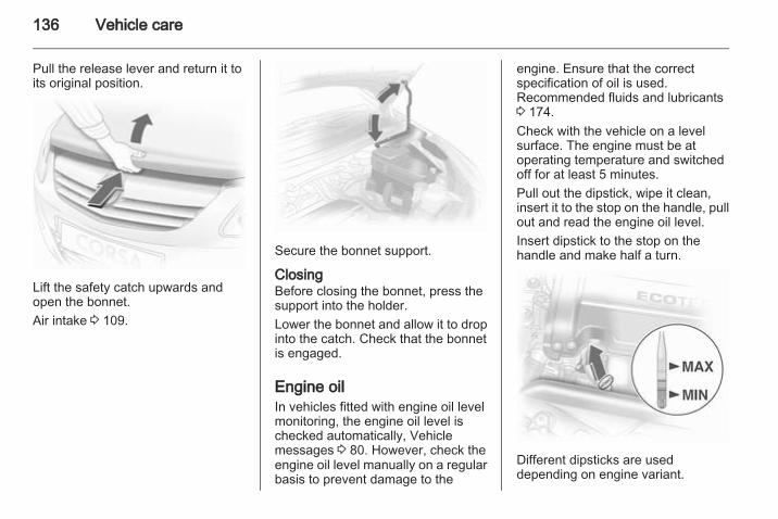
136 Vehicle care
Pull the release lever and return it toits original position.
Lift the safety catch upwards andopen the bonnet.Air intake 3 109.
Secure the bonnet support.
ClosingBefore closing the bonnet, press thesupport into the holder.Lower the bonnet and allow it to dropinto the catch. Check that the bonnetis engaged.
Engine oilIn vehicles fitted with engine oil levelmonitoring, the engine oil level ischecked automatically, Vehiclemessages 3 80. However, check theengine oil level manually on a regularbasis to prevent damage to the
engine. Ensure that the correctspecification of oil is used.Recommended fluids and lubricants3 174.Check with the vehicle on a levelsurface. The engine must be atoperating temperature and switchedoff for at least 5 minutes.Pull out the dipstick, wipe it clean,insert it to the stop on the handle, pullout and read the engine oil level.Insert dipstick to the stop on thehandle and make half a turn.
Different dipsticks are useddepending on engine variant.
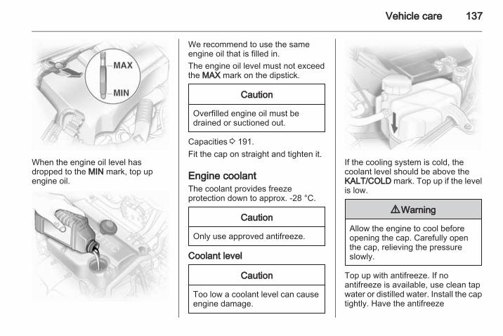
Vehicle care 137
When the engine oil level hasdropped to the MIN mark, top upengine oil.
We recommend to use the sameengine oil that is filled in.The engine oil level must not exceedthe MAX mark on the dipstick.
Caution
Overfilled engine oil must bedrained or suctioned out.
Capacities 3 191.Fit the cap on straight and tighten it.
Engine coolantThe coolant provides freezeprotection down to approx. -28 °C.
Caution
Only use approved antifreeze.
Coolant level
Caution
Too low a coolant level can causeengine damage.
If the cooling system is cold, thecoolant level should be above theKALT/COLD mark. Top up if the levelis low.
9 Warning
Allow the engine to cool beforeopening the cap. Carefully openthe cap, relieving the pressureslowly.
Top up with antifreeze. If noantifreeze is available, use clean tapwater or distilled water. Install the captightly. Have the antifreeze
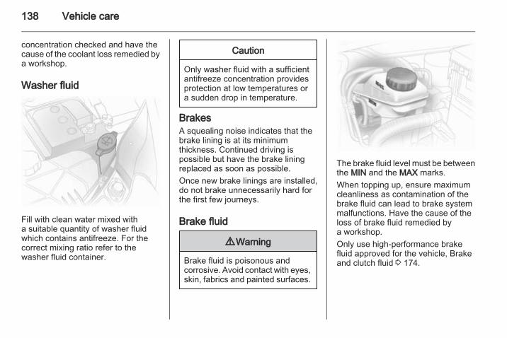
138 Vehicle care
concentration checked and have thecause of the coolant loss remedied bya workshop.
Washer fluid
Fill with clean water mixed witha suitable quantity of washer fluidwhich contains antifreeze. For thecorrect mixing ratio refer to thewasher fluid container.
Caution
Only washer fluid with a sufficientantifreeze concentration providesprotection at low temperatures ora sudden drop in temperature.
BrakesA squealing noise indicates that thebrake lining is at its minimumthickness. Continued driving ispossible but have the brake liningreplaced as soon as possible.Once new brake linings are installed,do not brake unnecessarily hard forthe first few journeys.
Brake fluid
9 Warning
Brake fluid is poisonous andcorrosive. Avoid contact with eyes,skin, fabrics and painted surfaces.
The brake fluid level must be betweenthe MIN and the MAX marks.When topping up, ensure maximumcleanliness as contamination of thebrake fluid can lead to brake systemmalfunctions. Have the cause of theloss of brake fluid remedied bya workshop.Only use high-performance brakefluid approved for the vehicle, Brakeand clutch fluid 3 174.
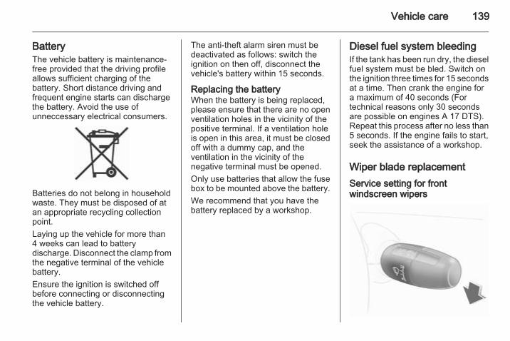
Vehicle care 139
BatteryThe vehicle battery is maintenance-free provided that the driving profileallows sufficient charging of thebattery. Short distance driving andfrequent engine starts can dischargethe battery. Avoid the use ofunneccessary electrical consumers.
Batteries do not belong in householdwaste. They must be disposed of atan appropriate recycling collectionpoint.Laying up the vehicle for more than4 weeks can lead to batterydischarge. Disconnect the clamp fromthe negative terminal of the vehiclebattery.Ensure the ignition is switched offbefore connecting or disconnectingthe vehicle battery.
The anti-theft alarm siren must bedeactivated as follows: switch theignition on then off, disconnect thevehicle's battery within 15 seconds.
Replacing the batteryWhen the battery is being replaced,please ensure that there are no openventilation holes in the vicinity of thepositive terminal. If a ventilation holeis open in this area, it must be closedoff with a dummy cap, and theventilation in the vicinity of thenegative terminal must be opened.Only use batteries that allow the fusebox to be mounted above the battery.We recommend that you have thebattery replaced by a workshop.
Diesel fuel system bleedingIf the tank has been run dry, the dieselfuel system must be bled. Switch onthe ignition three times for 15 secondsat a time. Then crank the engine fora maximum of 40 seconds (Fortechnical reasons only 30 secondsare possible on engines A 17 DTS).Repeat this process after no less than5 seconds. If the engine fails to start,seek the assistance of a workshop.
Wiper blade replacementService setting for frontwindscreen wipers
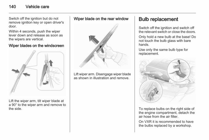
140 Vehicle care
Switch off the ignition but do notremove ignition key or open driver'sdoor.Within 4 seconds, push the wiperlever down and release as soon asthe wipers are vertical.
Wiper blades on the windscreen
Lift the wiper arm, tilt wiper blade ata 90° to the wiper arm and remove tothe side.
Wiper blade on the rear window
Lift wiper arm. Disengage wiper bladeas shown in illustration and remove.
Bulb replacementSwitch off the ignition and switch offthe relevant switch or close the doors.Only hold a new bulb at the base! Donot touch the bulb glass with barehands.Use only the same bulb type forreplacement.
To replace bulbs on the right side ofthe engine compartment, detach theair hose from the air filter.On VXR it is recommended to havethe bulbs replaced by a workshop.
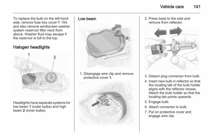
Vehicle care 141
To replace the bulb on the left-handside, remove fuse box cover 3 154,and also remove windscreen washersystem reservoir filler neck fromabove. Washer fluid may escape ifthe reservoir is full to the top.
Halogen headlights
Headlights have separate systems forlow beam 1 (outer bulbs) and highbeam 2 (inner bulbs).
Low beam
1. Disengage wire clip and removeprotective cover 1.
2. Press base to the side andremove from reflector.
3. Detach plug connector from bulb.4. Insert new bulb in reflector so that
the locating tab of the bulb holderaligns with the reflector recess.Attach the bulb holder so that thelocating tab points upwards.
5. Engage bulb.6. Attach connector to bulb.7. Put on protective cover and
engage wire clip.
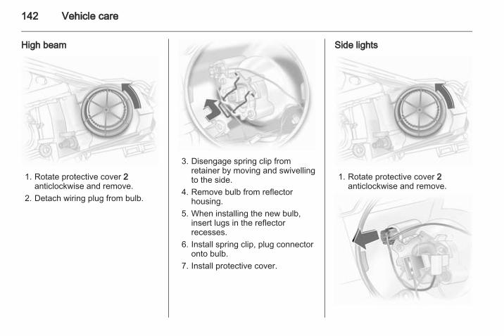
142 Vehicle care
High beam
1. Rotate protective cover 2anticlockwise and remove.
2. Detach wiring plug from bulb.
3. Disengage spring clip fromretainer by moving and swivellingto the side.
4. Remove bulb from reflectorhousing.
5. When installing the new bulb,insert lugs in the reflectorrecesses.
6. Install spring clip, plug connectoronto bulb.
7. Install protective cover.
Side lights
1. Rotate protective cover 2anticlockwise and remove.
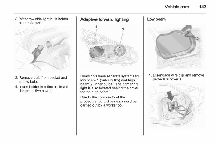
Vehicle care 143
2. Withdraw side light bulb holderfrom reflector.
3. Remove bulb from socket andrenew bulb.
4. Insert holder in reflector. Installthe protective cover.
Adaptive forward lighting
Headlights have separate systems forlow beam 1 (outer bulbs) and highbeam 2 (inner bulbs). The corneringlight is also located behind the coverfor the high beam.Due to the complexity of theprocedure, bulb changes should becarried out by a workshop.
Low beam
1. Disengage wire clip and removeprotective cover 1.
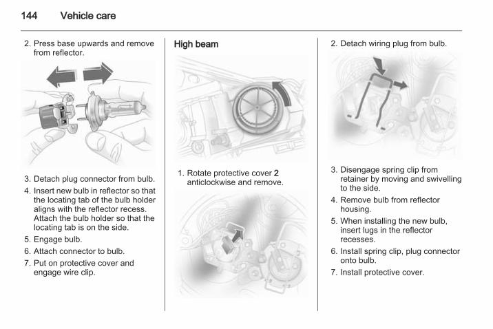
144 Vehicle care
2. Press base upwards and removefrom reflector.
3. Detach plug connector from bulb.4. Insert new bulb in reflector so that
the locating tab of the bulb holderaligns with the reflector recess.Attach the bulb holder so that thelocating tab is on the side.
5. Engage bulb.6. Attach connector to bulb.7. Put on protective cover and
engage wire clip.
High beam
1. Rotate protective cover 2anticlockwise and remove.
2. Detach wiring plug from bulb.
3. Disengage spring clip fromretainer by moving and swivellingto the side.
4. Remove bulb from reflectorhousing.
5. When installing the new bulb,insert lugs in the reflectorrecesses.
6. Install spring clip, plug connectoronto bulb.
7. Install protective cover.
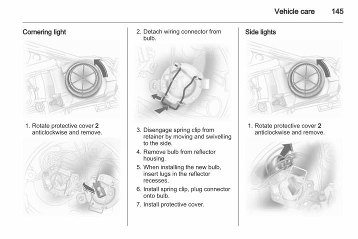
Vehicle care 145
Cornering light
1. Rotate protective cover 2anticlockwise and remove.
2. Detach wiring connector frombulb.
3. Disengage spring clip fromretainer by moving and swivellingto the side.
4. Remove bulb from reflectorhousing.
5. When installing the new bulb,insert lugs in the reflectorrecesses.
6. Install spring clip, plug connectoronto bulb.
7. Install protective cover.
Side lights
1. Rotate protective cover 2anticlockwise and remove.
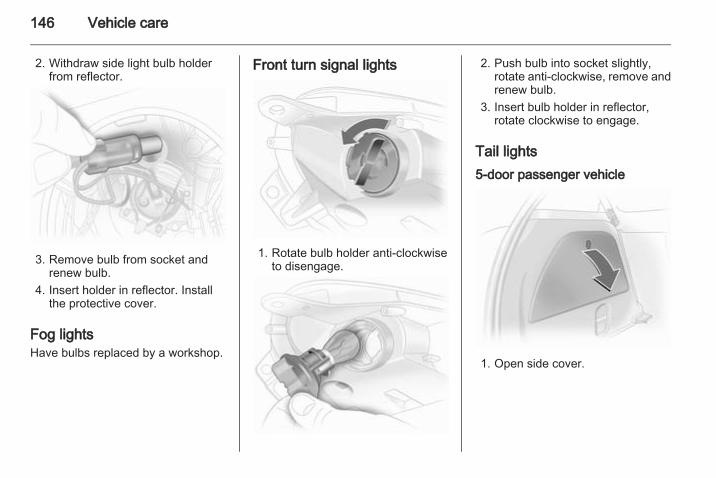
146 Vehicle care
2. Withdraw side light bulb holderfrom reflector.
3. Remove bulb from socket andrenew bulb.
4. Insert holder in reflector. Installthe protective cover.
Fog lightsHave bulbs replaced by a workshop.
Front turn signal lights
1. Rotate bulb holder anti-clockwiseto disengage.
2. Push bulb into socket slightly,rotate anti-clockwise, remove andrenew bulb.
3. Insert bulb holder in reflector,rotate clockwise to engage.
Tail lights5-door passenger vehicle
1. Open side cover.
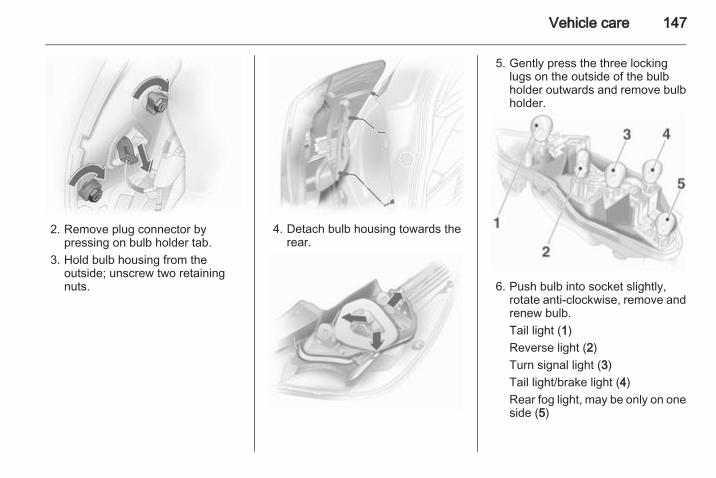
Vehicle care 147
2. Remove plug connector bypressing on bulb holder tab.
3. Hold bulb housing from theoutside; unscrew two retainingnuts.
4. Detach bulb housing towards therear.
5. Gently press the three lockinglugs on the outside of the bulbholder outwards and remove bulbholder.
6. Push bulb into socket slightly,rotate anti-clockwise, remove andrenew bulb.Tail light (1)Reverse light (2)Turn signal light (3)Tail light/brake light (4)Rear fog light, may be only on oneside (5)
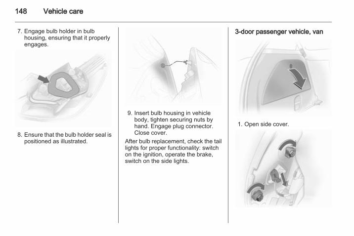
148 Vehicle care
7. Engage bulb holder in bulbhousing, ensuring that it properlyengages.
8. Ensure that the bulb holder seal ispositioned as illustrated.
9. Insert bulb housing in vehiclebody, tighten securing nuts byhand. Engage plug connector.Close cover.
After bulb replacement, check the taillights for proper functionality: switchon the ignition, operate the brake,switch on the side lights.
3-door passenger vehicle, van
1. Open side cover.
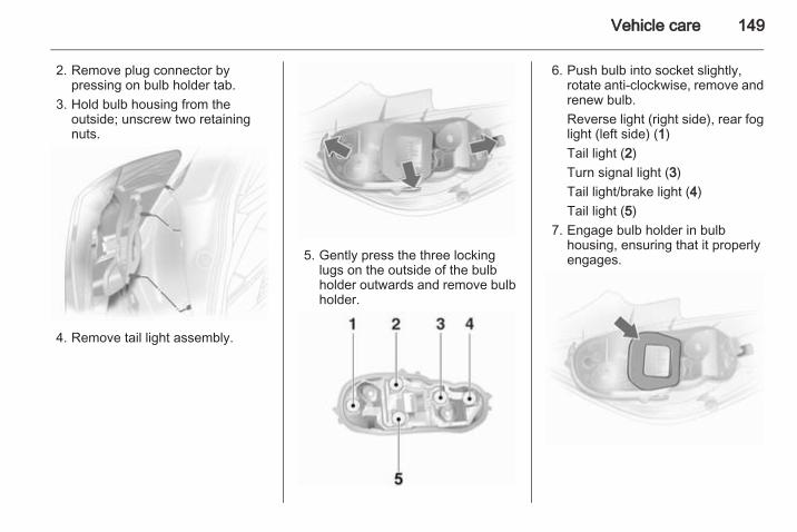
Vehicle care 149
2. Remove plug connector bypressing on bulb holder tab.
3. Hold bulb housing from theoutside; unscrew two retainingnuts.
4. Remove tail light assembly.
5. Gently press the three lockinglugs on the outside of the bulbholder outwards and remove bulbholder.
6. Push bulb into socket slightly,rotate anti-clockwise, remove andrenew bulb.Reverse light (right side), rear foglight (left side) (1)Tail light (2)Turn signal light (3)Tail light/brake light (4)Tail light (5)
7. Engage bulb holder in bulbhousing, ensuring that it properlyengages.
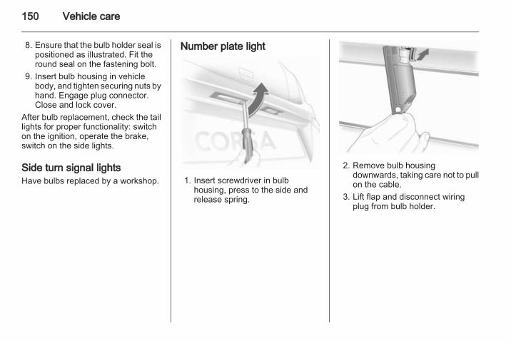
150 Vehicle care
8. Ensure that the bulb holder seal ispositioned as illustrated. Fit theround seal on the fastening bolt.
9. Insert bulb housing in vehiclebody, and tighten securing nuts byhand. Engage plug connector.Close and lock cover.
After bulb replacement, check the taillights for proper functionality: switchon the ignition, operate the brake,switch on the side lights.
Side turn signal lightsHave bulbs replaced by a workshop.
Number plate light
1. Insert screwdriver in bulbhousing, press to the side andrelease spring.
2. Remove bulb housingdownwards, taking care not to pullon the cable.
3. Lift flap and disconnect wiringplug from bulb holder.
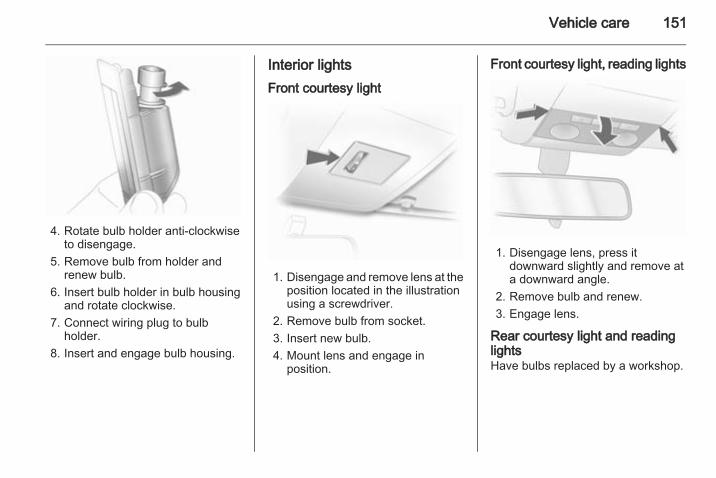
Vehicle care 151
4. Rotate bulb holder anti-clockwiseto disengage.
5. Remove bulb from holder andrenew bulb.
6. Insert bulb holder in bulb housingand rotate clockwise.
7. Connect wiring plug to bulbholder.
8. Insert and engage bulb housing.
Interior lightsFront courtesy light
1. Disengage and remove lens at theposition located in the illustrationusing a screwdriver.
2. Remove bulb from socket.3. Insert new bulb.4. Mount lens and engage in
position.
Front courtesy light, reading lights
1. Disengage lens, press itdownward slightly and remove ata downward angle.
2. Remove bulb and renew.3. Engage lens.
Rear courtesy light and readinglightsHave bulbs replaced by a workshop.
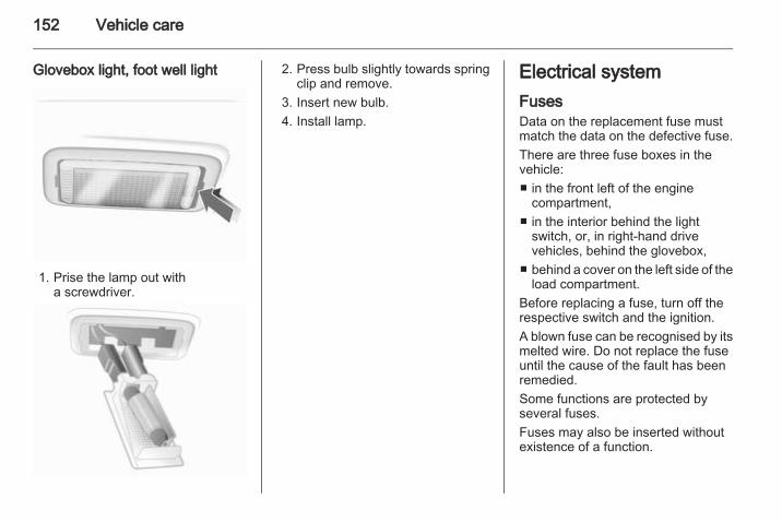
152 Vehicle care
Glovebox light, foot well light
1. Prise the lamp out witha screwdriver.
2. Press bulb slightly towards springclip and remove.
3. Insert new bulb.4. Install lamp.
Electrical systemFusesData on the replacement fuse mustmatch the data on the defective fuse.There are three fuse boxes in thevehicle:■ in the front left of the engine
compartment,■ in the interior behind the light
switch, or, in right-hand drivevehicles, behind the glovebox,
■ behind a cover on the left side of theload compartment.
Before replacing a fuse, turn off therespective switch and the ignition.A blown fuse can be recognised by itsmelted wire. Do not replace the fuseuntil the cause of the fault has beenremedied.Some functions are protected byseveral fuses.Fuses may also be inserted withoutexistence of a function.
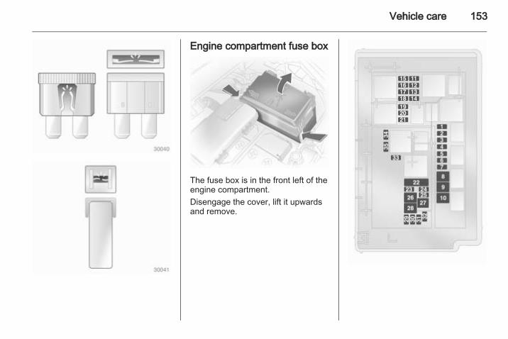
Vehicle care 153
Engine compartment fuse box
The fuse box is in the front left of theengine compartment.Disengage the cover, lift it upwardsand remove.
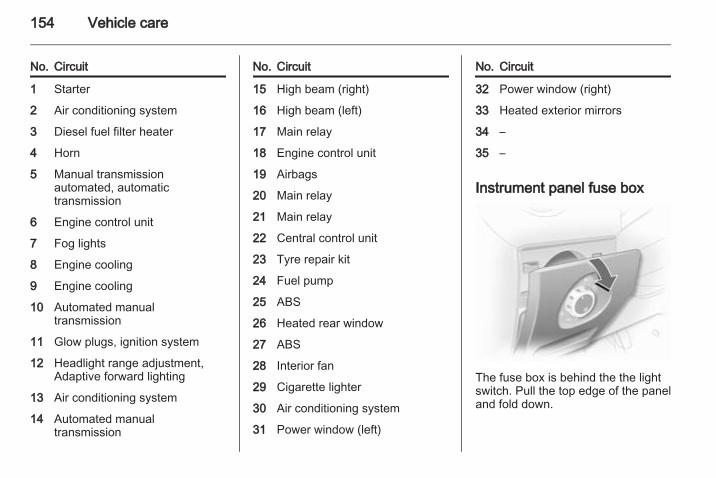
154 Vehicle care
No. Circuit
1 Starter
2 Air conditioning system
3 Diesel fuel filter heater
4 Horn
5 Manual transmissionautomated, automatictransmission
6 Engine control unit
7 Fog lights
8 Engine cooling
9 Engine cooling
10 Automated manualtransmission
11 Glow plugs, ignition system
12 Headlight range adjustment,Adaptive forward lighting
13 Air conditioning system
14 Automated manualtransmission
No. Circuit
15 High beam (right)
16 High beam (left)
17 Main relay
18 Engine control unit
19 Airbags
20 Main relay
21 Main relay
22 Central control unit
23 Tyre repair kit
24 Fuel pump
25 ABS
26 Heated rear window
27 ABS
28 Interior fan
29 Cigarette lighter
30 Air conditioning system
31 Power window (left)
No. Circuit
32 Power window (right)
33 Heated exterior mirrors
34 –
35 –
Instrument panel fuse box
The fuse box is behind the the lightswitch. Pull the top edge of the paneland fold down.
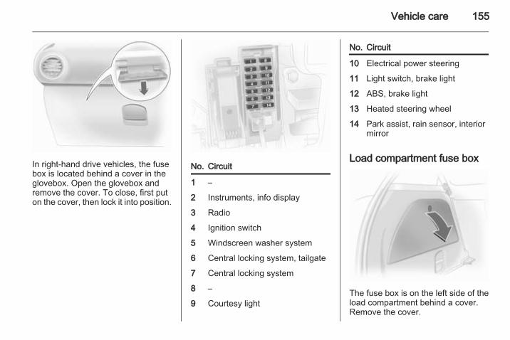
Vehicle care 155
In right-hand drive vehicles, the fusebox is located behind a cover in theglovebox. Open the glovebox andremove the cover. To close, first puton the cover, then lock it into position.
No. Circuit
1 –
2 Instruments, info display
3 Radio
4 Ignition switch
5 Windscreen washer system
6 Central locking system, tailgate
7 Central locking system
8 –
9 Courtesy light
No. Circuit
10 Electrical power steering
11 Light switch, brake light
12 ABS, brake light
13 Heated steering wheel
14 Park assist, rain sensor, interiormirror
Load compartment fuse box
The fuse box is on the left side of theload compartment behind a cover.Remove the cover.
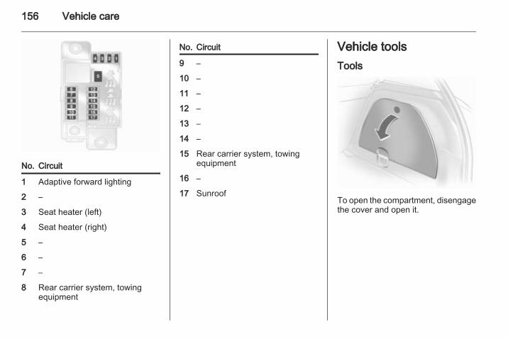
156 Vehicle care
No. Circuit
1 Adaptive forward lighting
2 –
3 Seat heater (left)
4 Seat heater (right)
5 –
6 –
7 –
8 Rear carrier system, towingequipment
No. Circuit
9 –
10 –
11 –
12 –
13 –
14 –
15 Rear carrier system, towingequipment
16 –
17 Sunroof
Vehicle toolsTools
To open the compartment, disengagethe cover and open it.
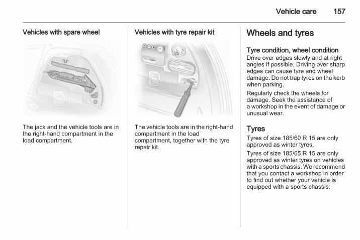
Vehicle care 157
Vehicles with spare wheel
The jack and the vehicle tools are inthe right-hand compartment in theload compartment.
Vehicles with tyre repair kit
The vehicle tools are in the right-handcompartment in the loadcompartment, together with the tyrerepair kit.
Wheels and tyres
Tyre condition, wheel conditionDrive over edges slowly and at rightangles if possible. Driving over sharpedges can cause tyre and wheeldamage. Do not trap tyres on the kerbwhen parking.Regularly check the wheels fordamage. Seek the assistance ofa workshop in the event of damage orunusual wear.
TyresTyres of size 185/60 R 15 are onlyapproved as winter tyres.Tyres of size 185/65 R 15 are onlyapproved as winter tyres on vehicleswith a sports chassis. We recommendthat you contact a workshop in orderto find out whether your vehicle isequipped with a sports chassis.
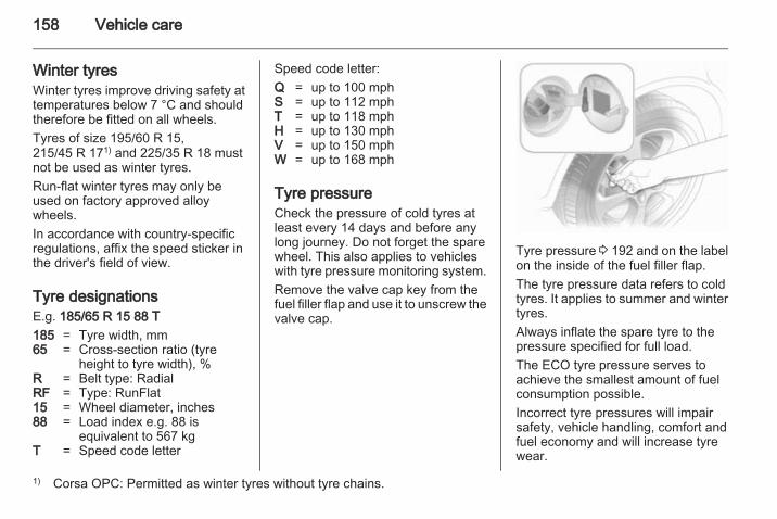
158 Vehicle care
Winter tyresWinter tyres improve driving safety attemperatures below 7 °C and shouldtherefore be fitted on all wheels.Tyres of size 195/60 R 15,215/45 R 171) and 225/35 R 18 mustnot be used as winter tyres.Run-flat winter tyres may only beused on factory approved alloywheels.In accordance with country-specificregulations, affix the speed sticker inthe driver's field of view.
Tyre designationsE.g. 185/65 R 15 88 T185 = Tyre width, mm65 = Cross-section ratio (tyre
height to tyre width), %R = Belt type: RadialRF = Type: RunFlat15 = Wheel diameter, inches88 = Load index e.g. 88 is
equivalent to 567 kgT = Speed code letter
Speed code letter:Q = up to 100 mphS = up to 112 mphT = up to 118 mphH = up to 130 mphV = up to 150 mphW = up to 168 mph
Tyre pressureCheck the pressure of cold tyres atleast every 14 days and before anylong journey. Do not forget the sparewheel. This also applies to vehicleswith tyre pressure monitoring system.Remove the valve cap key from thefuel filler flap and use it to unscrew thevalve cap.
Tyre pressure 3 192 and on the labelon the inside of the fuel filler flap.The tyre pressure data refers to coldtyres. It applies to summer and wintertyres.Always inflate the spare tyre to thepressure specified for full load.The ECO tyre pressure serves toachieve the smallest amount of fuelconsumption possible.Incorrect tyre pressures will impairsafety, vehicle handling, comfort andfuel economy and will increase tyrewear.
1) Corsa OPC: Permitted as winter tyres without tyre chains.
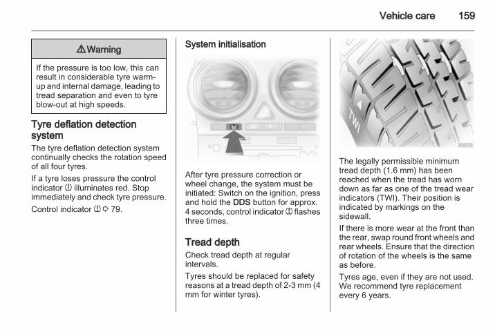
Vehicle care 159
9 Warning
If the pressure is too low, this canresult in considerable tyre warm-up and internal damage, leading totread separation and even to tyreblow-out at high speeds.
Tyre deflation detectionsystemThe tyre deflation detection systemcontinually checks the rotation speedof all four tyres.If a tyre loses pressure the controlindicator w illuminates red. Stopimmediately and check tyre pressure.Control indicator w 3 79.
System initialisation
After tyre pressure correction orwheel change, the system must beinitiated: Switch on the ignition, pressand hold the DDS button for approx.4 seconds, control indicator w flashesthree times.
Tread depthCheck tread depth at regularintervals.Tyres should be replaced for safetyreasons at a tread depth of 2-3 mm (4mm for winter tyres).
The legally permissible minimumtread depth (1.6 mm) has beenreached when the tread has worndown as far as one of the tread wearindicators (TWI). Their position isindicated by markings on thesidewall.If there is more wear at the front thanthe rear, swap round front wheels andrear wheels. Ensure that the directionof rotation of the wheels is the sameas before.Tyres age, even if they are not used.We recommend tyre replacementevery 6 years.
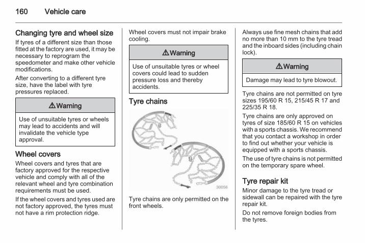
160 Vehicle care
Changing tyre and wheel sizeIf tyres of a different size than thosefitted at the factory are used, it may benecessary to reprogram thespeedometer and make other vehiclemodifications.After converting to a different tyresize, have the label with tyrepressures replaced.
9 Warning
Use of unsuitable tyres or wheelsmay lead to accidents and willinvalidate the vehicle typeapproval.
Wheel coversWheel covers and tyres that arefactory approved for the respectivevehicle and comply with all of therelevant wheel and tyre combinationrequirements must be used.If the wheel covers and tyres used arenot factory approved, the tyres mustnot have a rim protection ridge.
Wheel covers must not impair brakecooling.
9 Warning
Use of unsuitable tyres or wheelcovers could lead to suddenpressure loss and therebyaccidents.
Tyre chains
Tyre chains are only permitted on thefront wheels.
Always use fine mesh chains that addno more than 10 mm to the tyre treadand the inboard sides (including chainlock).
9 Warning
Damage may lead to tyre blowout.
Tyre chains are not permitted on tyresizes 195/60 R 15, 215/45 R 17 and225/35 R 18.Tyre chains are only approved ontyres of size 185/60 R 15 on vehicleswith a sports chassis. We recommendthat you contact a workshop in orderto find out whether your vehicle isequipped with a sports chassis.The use of tyre chains is not permittedon the temporary spare wheel.
Tyre repair kitMinor damage to the tyre tread orsidewall can be repaired with the tyrerepair kit.Do not remove foreign bodies fromthe tyres.
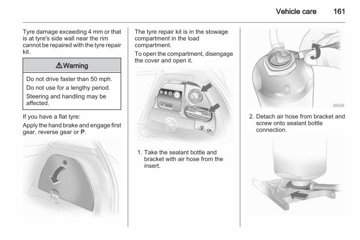
Vehicle care 161
Tyre damage exceeding 4 mm or thatis at tyre's side wall near the rimcannot be repaired with the tyre repairkit.
9 Warning
Do not drive faster than 50 mph.Do not use for a lengthy period.Steering and handling may beaffected.
If you have a flat tyre:Apply the hand brake and engage firstgear, reverse gear or P.
The tyre repair kit is in the stowagecompartment in the loadcompartment.To open the compartment, disengagethe cover and open it.
1. Take the sealant bottle andbracket with air hose from theinsert.
2. Detach air hose from bracket andscrew onto sealant bottleconnection.
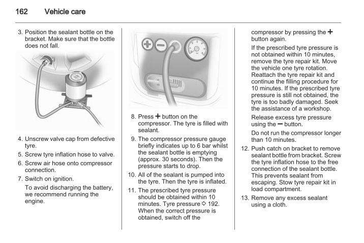
162 Vehicle care
3. Position the sealant bottle on thebracket. Make sure that the bottledoes not fall.
4. Unscrew valve cap from defectivetyre.
5. Screw tyre inflation hose to valve.6. Screw air hose onto compressor
connection.7. Switch on ignition.
To avoid discharging the battery,we recommend running theengine.
8. Press < button on thecompressor. The tyre is filled withsealant.
9. The compressor pressure gaugebriefly indicates up to 6 bar whilstthe sealant bottle is emptying(approx. 30 seconds). Then thepressure starts to drop.
10. All of the sealant is pumped intothe tyre. Then the tyre is inflated.
11. The prescribed tyre pressureshould be obtained within 10minutes. Tyre pressure 3 192.When the correct pressure isobtained, switch off the
compressor by pressing the <button again.If the prescribed tyre pressure isnot obtained within 10 minutes,remove the tyre repair kit. Movethe vehicle one tyre rotation.Reattach the tyre repair kit andcontinue the filling procedure for10 minutes. If the prescribed tyrepressure is still not obtained, thetyre is too badly damaged. Seekthe assistance of a workshop.Release excess tyre pressureusing the ] button.Do not run the compressor longerthan 10 minutes.
12. Push catch on bracket to removesealant bottle from bracket. Screwthe tyre inflation hose to the freeconnection of the sealant bottle.This prevents sealant fromescaping. Stow tyre repair kit inload compartment.
13. Remove any excess sealantusing a cloth.
Vehicle care 163
14. Take the label indicatingmaximum permitted speed fromthe sealant bottle and affix in thedriver's field of view.
15. Continue driving immediately sothat sealant is evenly distributedin the tyre. After driving approx.6 miles (but no more than 10minutes), stop and check tyrepressure. Screw compressor airhose directly onto tyre valve andcompressor when doing this.If tyre pressure is more than 1.3bar, set it to the correct value.Repeat the procedure until thereis no more loss of pressure.If the tyre pressure has fallenbelow 1.3 bar, the vehicle mustnot be used. Seek the assistanceof a workshop.
16. Stow away tyre repair kit in loadcompartment.
NoteThe driving characteristics of therepaired tyre is severely affected,therefore have this tyre replaced.If unusual noise is heard or thecompressor becomes hot, turncompressor off for at least 30minutes.The built-in safety valve opens ata pressure of 7 bar.Note the expiry date of the kit. Afterthis date its sealing capability is nolonger guaranteed. Pay attention tostorage information on sealantbottle.Replace the used sealant bottle.Dispose of the bottle as prescribedby applicable laws.The compressor and sealant can beused from approx. -30 °C.The adapters supplied can be usedto pump up other items e.g.footballs, air mattresses, inflatabledinghies etc. They are located on theunderside of the compressor. Toremove, screw on compressor airhose and withdraw adapter.
Wheel changingSome vehicles are equipped witha tyre repair kit instead of a sparewheel 3 160.Make the following preparations andobserve the following information:■ Park the vehicle on a level, firm and
non-skid surface. The front wheelsmust be in the straight-aheadposition.
■ Apply the parking brake andengage first gear, reverse gear orP.
■ Remove the spare wheel 3 165.■ Never change more than one wheel
at once.■ Use the jack only to change wheels
in case of puncture, not forseasonal winter or summer tyrechange.
■ If the ground on which the vehicleis standing is soft, a solid board(max. 0.4 inches thick) should beplaced under the jack.
■ No people or animals may be in thevehicle when it is jacked-up.
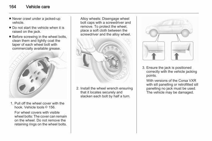
164 Vehicle care
■ Never crawl under a jacked-upvehicle.
■ Do not start the vehicle when it israised on the jack.
■ Before screwing in the wheel bolts,clean them and lightly coat thetaper of each wheel bolt withcommercially available grease.
1. Pull off the wheel cover with thehook. Vehicle tools 3 156.For wheel covers with visiblewheel bolts: The cover can remainon the wheel. Do not remove theretaining rings on the wheel bolts.
Alloy wheels: Disengage wheelbolt caps with a screwdriver andremove. To protect the wheel,place a soft cloth between thescrewdriver and the alloy wheel.
2. Install the wheel wrench ensuringthat it locates securely andslacken each bolt by half a turn.
3. Ensure the jack is positionedcorrectly with the vehicle jackingpoints.With versions of the Corsa VXRwith sill panelling or retrofitted sillpanelling no jack must be used.The vehicle may be damaged.
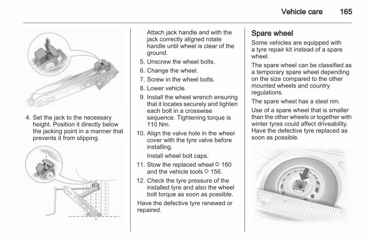
Vehicle care 165
4. Set the jack to the necessaryheight. Position it directly belowthe jacking point in a manner thatprevents it from slipping.
Attach jack handle and with thejack correctly aligned rotatehandle until wheel is clear of theground.
5. Unscrew the wheel bolts.6. Change the wheel.7. Screw in the wheel bolts.8. Lower vehicle.9. Install the wheel wrench ensuring
that it locates securely and tighteneach bolt in a crosswisesequence. Tightening torque is110 Nm.
10. Align the valve hole in the wheelcover with the tyre valve beforeinstalling.Install wheel bolt caps.
11. Stow the replaced wheel 3 160and the vehicle tools 3 156.
12. Check the tyre pressure of theinstalled tyre and also the wheelbolt torque as soon as possible.
Have the defective tyre renewed orrepaired.
Spare wheelSome vehicles are equipped witha tyre repair kit instead of a sparewheel.The spare wheel can be classified asa temporary spare wheel dependingon the size compared to the othermounted wheels and countryregulations.The spare wheel has a steel rim.Use of a spare wheel that is smallerthan the other wheels or together withwinter tyres could affect driveability.Have the defective tyre replaced assoon as possible.
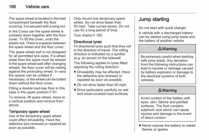
166 Vehicle care
The spare wheel is located in the loadcompartment beneath the floorcovering. It is secured with a wing nut.In the Corsa van the spare wheel isscrewed down together with the floorcover. To lift the cover, undo theplastic nut. There is a spacer betweenthe spare wheel and the floor cover.The spare wheel well is not designedfor all permitted tyre sizes. If a wheelwider than the spare must be stowedin the spare wheel well after changingwheels, the floor cover will be restingagainst the protruding wheel. In vansthe spacer can be omitted ifnecessary, or the wheel can be bolteddown without the floor cover.Fitting a double load-bay floor in thiscase in the upper position 3 61.To remove, lift spare wheel, move toa vertical position and remove fromabove.
Temporary spare wheelUse of the temporary spare wheelcould affect driveability. Have thedefective tyre renewed or repaired assoon as possible.
Only mount one temporary sparewheel. Do not drive faster than50 mph. Take curves slowly. Do notuse for a long period of time.Tyre chains 3 160.
Directional tyresFit directional tyres such that they rollin the direction of travel. The rollingdirection is indicated by a symbol(e.g. an arrow) on the sidewall.The following applies to tyres fittedopposing the rolling direction:■ Driveability may be affected. Have
the defective tyre renewed orrepaired as soon as possible.
■ Do not drive faster than 50 mph.■ Drive particularly carefully on wet
and snow-covered road surfaces.
Jump startingDo not start with quick charger.A vehicle with a discharged batterycan be started using jump leads andthe battery of another vehicle.
9 Warning
Be extremely careful when startingwith jump leads. Any deviationfrom the following instructions canlead to injuries or damage causedby battery explosion or damage tothe electrical systems of bothvehicles.
9 Warning
Avoid contact of the battery witheyes, skin, fabrics and paintedsurfaces. The fluid containssulphuric acid which can causeinjuries and damage in the eventof direct contact.
■ Never expose the battery to nakedflames or sparks.
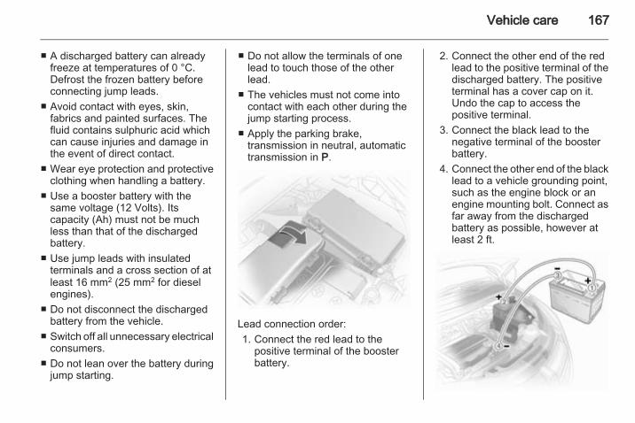
Vehicle care 167
■ A discharged battery can alreadyfreeze at temperatures of 0 °C.Defrost the frozen battery beforeconnecting jump leads.
■ Avoid contact with eyes, skin,fabrics and painted surfaces. Thefluid contains sulphuric acid whichcan cause injuries and damage inthe event of direct contact.
■ Wear eye protection and protectiveclothing when handling a battery.
■ Use a booster battery with thesame voltage (12 Volts). Itscapacity (Ah) must not be muchless than that of the dischargedbattery.
■ Use jump leads with insulatedterminals and a cross section of atleast 16 mm2 (25 mm2 for dieselengines).
■ Do not disconnect the dischargedbattery from the vehicle.
■ Switch off all unnecessary electricalconsumers.
■ Do not lean over the battery duringjump starting.
■ Do not allow the terminals of onelead to touch those of the otherlead.
■ The vehicles must not come intocontact with each other during thejump starting process.
■ Apply the parking brake,transmission in neutral, automatictransmission in P.
Lead connection order:1. Connect the red lead to the
positive terminal of the boosterbattery.
2. Connect the other end of the redlead to the positive terminal of thedischarged battery. The positiveterminal has a cover cap on it.Undo the cap to access thepositive terminal.
3. Connect the black lead to thenegative terminal of the boosterbattery.
4. Connect the other end of the blacklead to a vehicle grounding point,such as the engine block or anengine mounting bolt. Connect asfar away from the dischargedbattery as possible, however atleast 2 ft.
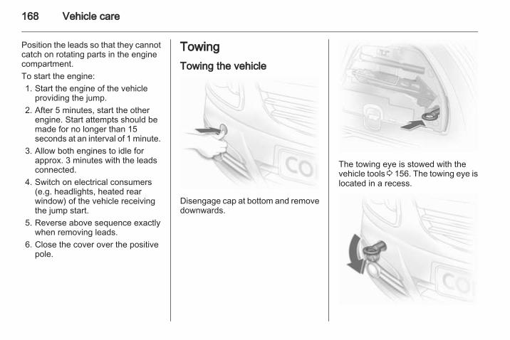
168 Vehicle care
Position the leads so that they cannotcatch on rotating parts in the enginecompartment.To start the engine:1. Start the engine of the vehicle
providing the jump.2. After 5 minutes, start the other
engine. Start attempts should bemade for no longer than 15seconds at an interval of 1 minute.
3. Allow both engines to idle forapprox. 3 minutes with the leadsconnected.
4. Switch on electrical consumers(e.g. headlights, heated rearwindow) of the vehicle receivingthe jump start.
5. Reverse above sequence exactlywhen removing leads.
6. Close the cover over the positivepole.
TowingTowing the vehicle
Disengage cap at bottom and removedownwards.
The towing eye is stowed with thevehicle tools 3 156. The towing eye islocated in a recess.
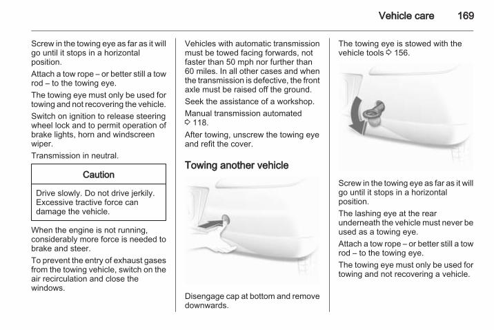
Vehicle care 169
Screw in the towing eye as far as it willgo until it stops in a horizontalposition.Attach a tow rope – or better still a towrod – to the towing eye.The towing eye must only be used fortowing and not recovering the vehicle.Switch on ignition to release steeringwheel lock and to permit operation ofbrake lights, horn and windscreenwiper.Transmission in neutral.
Caution
Drive slowly. Do not drive jerkily.Excessive tractive force candamage the vehicle.
When the engine is not running,considerably more force is needed tobrake and steer.To prevent the entry of exhaust gasesfrom the towing vehicle, switch on theair recirculation and close thewindows.
Vehicles with automatic transmissionmust be towed facing forwards, notfaster than 50 mph nor further than60 miles. In all other cases and whenthe transmission is defective, the frontaxle must be raised off the ground.Seek the assistance of a workshop.Manual transmission automated3 118.After towing, unscrew the towing eyeand refit the cover.
Towing another vehicle
Disengage cap at bottom and removedownwards.
The towing eye is stowed with thevehicle tools 3 156.
Screw in the towing eye as far as it willgo until it stops in a horizontalposition.The lashing eye at the rearunderneath the vehicle must never beused as a towing eye.Attach a tow rope – or better still a towrod – to the towing eye.The towing eye must only be used fortowing and not recovering a vehicle.
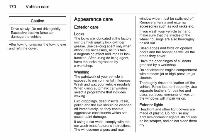
170 Vehicle care
Caution
Drive slowly. Do not drive jerkily.Excessive tractive force candamage the vehicle.
After towing, unscrew the towing eyeand refit the cover.
Appearance careExterior careLocksThe locks are lubricated at the factoryusing a high quality lock cylindergrease. Use de-icing agent only whenabsolutely necessary, as this hasa degreasing effect and impairs lockfunction. After using de-icing agent,have the locks regreased bya workshop.
WashingThe paintwork of your vehicle isexposed to environmental influences.Wash and wax your vehicle regularly.When using automatic car washes,select a programme that includeswaxing.Bird droppings, dead insects, resin,pollen and the like should be cleanedoff immediately, as they containaggressive constituents which cancause paint damage.If using a car wash, comply with thecar wash manufacturer's instructions.The windscreen wipers and rear
window wiper must be switched off.Remove antenna and externalaccessories such as roof racks etc.If you wash your vehicle by hand,make sure that the insides of thewheel housings are also thoroughlyrinsed out.Clean edges and folds on openeddoors and the bonnet as well as theareas they cover.Have the door hinges of all doorsgreased by a workshop.Do not clean the engine compartmentwith a steam-jet or high-pressure jetcleaner.Thoroughly rinse and leather-off thevehicle. Rinse leather frequently. Useseparate leathers for painted andglass surfaces: remnants of wax onthe windows will impair vision.
Exterior lightsHeadlight and other light covers aremade of plastic. Do not use anyabrasive or caustic agents, do not usean ice scraper, and do not clean themdry.
Vehicle care 171
Polishing and waxingWax the vehicle regularly (at thelatest when water no longer beads).Otherwise, the paintwork will dry out.Polishing is necessary only if the painthas become dull or if solid depositshave become attached to it.Paintwork polish with silicone formsa protective film, making waxingunnecessary.Plastic body parts must not be treatedwith wax or polishing agents.
Windows and windscreen wiperbladesUse a soft lint-free cloth or chamoisleather together with window cleanerand insect remover.When cleaning the rear window,make sure the heating element insideis not damaged.For mechanical removal of ice, usea sharp-edged ice scraper. Press thescraper firmly against the glass sothat no dirt can get under it andscratch the glass.
Clean smearing wiper blades witha soft cloth and window cleaner.
SunroofNever clean with solvents or abrasiveagents, fuels, aggressive media (e.g.paint cleaner, acetone-containingsolutions etc.), acidic or highlyalkaline media or abrasive pads. Donot apply wax or polishing agents tothe sunroof.
Wheels and tyresDo not use high-pressure jetcleaners.Clean rims with a pH-neutral wheelcleaner.Rims are painted and can be treatedwith the same agents as the body.
Paintwork damageRectify minor paintwork damage witha touch-up pen before rust forms.Have more extensive damage or rustareas repaired by a workshop.
UnderbodySome areas of the vehicle underbodyhave a PVC undercoating while othercritical areas have a durableprotective wax coating.After the underbody is washed, checkthe underbody and have it waxed ifnecessary.Bitumen/rubber materials coulddamage the PVC coating. Haveunderbody work carried out bya workshop.Before and after winter, wash theunderbody and have the protectivewax coating checked.
Towing equipmentDo not clean the coupling ball bar witha steam-jet or high-pressure jetcleaner.
Interior careInterior and upholsteryOnly clean the vehicle interior,including the instrument panel fasciaand panelling, with a dry cloth orinterior cleaner.
172 Vehicle care
The instrument panel should only becleaned using a soft damp cloth.Clean fabric upholstery witha vacuum cleaner and brush.Remove stains with an upholsterycleaner.Clean seat belts with lukewarm wateror interior cleaner.
Caution
Close Velcro fasteners as openVelcro fasteners on clothing coulddamage seat upholstery.The same applies to clothing withsharp-edged objects, like zips orbelts or studded jeans.
Plastic and rubber partsPlastic and rubber parts can becleaned with the same cleaner asused to clean the body. Use interiorcleaner if necessary. Do not use anyother agent. Avoid solvents and petrolin particular. Do not use high-pressure jet cleaners.
Service and maintenance 173
Service andmaintenance
General information ................... 173Recommended fluids, lubricantsand parts .................................... 174
General informationService informationIn order to ensure economical andsafe vehicle operation and tomaintain the value of your vehicle, itis of vital importance that allmaintenance work is carried out at theproper intervals as specified.The detailed, up-to-date serviceschedule for your vehicle is availableat the workshop.
European service intervalsService is due every 20,000 miles or1 year, whichever occurs first.The European schedule is valid forthe following countries:Andorra, Austria, Belgium, Bosnia-Herzegovina, Bulgaria, Croatia,Cyprus, Czech Republic, Denmark,Estonia, Finland, France, Germany,Greece, Greenland, Hungary,Iceland, Ireland, Italy, Latvia,Lithuania, Luxembourg, Macedonia,Malta, Montenegro, Netherlands,Norway, Poland, Portugal, Romania,
Serbia, Slovakia, Slovenia, Spain,Sweden, Switzerland, UnitedKingdom.
International service intervalsService is due every 10,000 miles or1 year, whichever occurs first.The international service intervals arevalid for the countries which are notlisted at the european serviceintervals.
ConfirmationsConfirmation of service is recorded inthe Service and Warranty Booklet.The date and mileage is completedwith the stamp and signature of theservicing workshop.Make sure that the Service andWarranty Booklet is completedcorrectly as continuous proof ofservice is essential if any warranty orgoodwill claims are to be met, and isalso a benefit when selling thevehicle.
174 Service and maintenance
Fixed service intervalWhen service is due, InSP appears inthe odometer display forapproximately 10 seconds when theignition is switched on. Have the nextservice performed by a workshopwithin one week or 300 miles(whichever occurs first).
Flexible service intervalThe service interval is based onseveral parameters depending onusage and calculated using theseparameters.If the remaining distance is lessthan1000 miles, InSP is displayedwith a remaining distance of600 miles when the ignition isswitched on and off. If less than600 miles remain, InSP is displayedfor several seconds. Have the nextservice performed by a workshopwithin one week or 300 miles(whichever occurs first).
Display of remaining distance:1. Switch off ignition.2. Briefly press the trip odometer
reset button. The odometerreading is shown.
3. Press and hold the reset button forapprox. 2 seconds. InSP and theremaining distance are displayed.
Recommended fluids,lubricants and partsRecommended fluids andlubricantsOnly use products that have beentested and approved. Damageresulting from the use of non-approved materials will not becovered by the warranty.
9 Warning
Operating materials arehazardous and could bepoisonous. Handle with care. Payattention to information given onthe containers.
Engine oilEngine oil is identified by its qualityand its viscosity. Quality is moreimportant than viscosity whenselecting which engine oil to use. Theoil quality ensures e.g. enginecleanliness, wear protection and oil
Service and maintenance 175
aging control, whereas viscositygrade gives information on the oil'sthickness over a temperature range.The new engine oil qualityDexos 2 TM is the newest oil qualityand combines gasoline and dieselperformance. If it is unavailable,engine oils of other listed qualitieshave to be used.
Engine oil quality for Europeanservice schedulesDexos 2 TM = All petrol and diesel
engines
Alternative qualities if Dexos 2 TM isnot available:GM-LL-A-025 = Petrol enginesGM-LL-B-025 = Diesel engines
Engine oil quality for internationalservice schedulesDexos 2 TM = All petrol and diesel
engines
Alternative qualities if Dexos 2 TM isnot available:GM-LL-A-025 = Petrol enginesGM-LL-B-025 = Diesel engines
Alternative qualities if GM-LL-A-025or GM-LL-B-025 are not available:ACEA-A3/B3 orA3/B4
= Petrol engines
ACEA-A3/B4 = Diesel engineswithout DieselParticle Filter(DPF)
ACEA-C3 = Diesel engineswith DPF
Topping up engine oilEngine oils of different manufacturersand brands can be mixed as long asthey comply with the required engineoil quality and viscosity.If engine oil of the required quality isnot available, a maximum of 1 litre ofACEA C3 grade may be used (onlyonce between each oil change). Theviscosity should be of one of thebelow listed viscosity grades.Use of engine oil with only ACEA A1/B1 or only A5/B5 quality is explicitlyprohibited, since it can cause long-term engine damage under certainoperating conditions.
Additional engine oil additivesThe use of additional engine oiladditives could cause damage andinvalidate the warranty.
Engine oil viscosity gradesUse only engine oil viscosity gradesSAE 5W-30 or 5W-40, 0W-30 or0W-40.The SAE viscosity grade givesinformation of the thickness of the oil.Multigrade oil is indicated by twofigures. The first figure, followed bya W, indicates the low temperatureviscosity and the second figure thehigh temperature viscosity. Pleaseselect the approriate viscosity gradedepending on your minimum ambienttemperature.■ down to -25°C:
SAE 5W-30 or SAE 5W-40■ below -25°C:
SAE 0W-30 or SAE 0W-40
Coolant and antifreezeUse only silicate-free long life coolant(LLC) antifreeze.
176 Service and maintenance
The system is factory filled withcoolant designed for excellentcorrosion protection and frostprotection down to approx. -28 °C.This concentration should bemaintained all year round. The use ofadditional coolant additives thatintend to give additional corrosionprotection or seal against minor leakscan cause function problems. Liabilityfor consequences resulting from theuse of additional coolant additives willbe rejected.
Brake and clutch fluidUse only brake fluid which exceedsDOT4 requirements.Over time, brake fluid absorbsmoisture which will reduce brakingeffectiveness. The brake fluid shouldtherefore be replaced at the specifiedinterval.Brake fluid should be stored ina sealed container to avoid waterabsorption.Ensure brake fluid does not becomecontaminated.
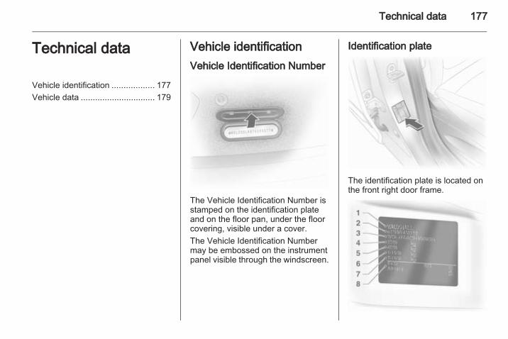
Technical data 177
Technical data
Vehicle identification .................. 177Vehicle data ............................... 179
Vehicle identificationVehicle Identification Number
The Vehicle Identification Number isstamped on the identification plateand on the floor pan, under the floorcovering, visible under a cover.The Vehicle Identification Numbermay be embossed on the instrumentpanel visible through the windscreen.
Identification plate
The identification plate is located onthe front right door frame.
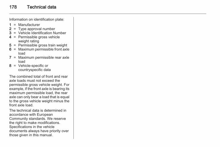
178 Technical data
Information on identification plate:1 = Manufacturer2 = Type approval number3 = Vehicle Identification Number4 = Permissible gross vehicle
weight rating5 = Permissible gross train weight6 = Maximum permissible front axle
load7 = Maximum permissible rear axle
load8 = Vehicle-specific or
countryspecific data
The combined total of front and rearaxle loads must not exceed thepermissible gross vehicle weight. Forexample, if the front axle is bearing itsmaximum permissible load, the rearaxle can only bear a load that is equalto the gross vehicle weight minus thefront axle load.The technical data is determined inaccordance with EuropeanCommunity standards. We reservethe right to make modifications.Specifications in the vehicledocuments always have priority overthose given in this manual.
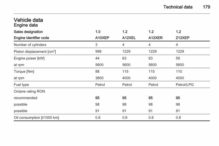
Technical data 179
Vehicle dataEngine dataSales designation 1.0 1.2 1.2 1.2Engine identifier code A10XEP A12XEL A12XER Z12XEP
Number of cylinders 3 4 4 4
Piston displacement [cm3] 998 1229 1229 1229
Engine power [kW] 44 63 63 59
at rpm 5600 5600 5600 5600
Torque [Nm] 88 115 115 110
at rpm 3800 4000 4000 4000
Fuel type Petrol Petrol Petrol Petrol/LPG
Octane rating RON
recommended 95 95 95 95
possible 98 98 98 98
possible 91 91 91 91
Oil consumption [l/1000 km] 0.6 0.6 0.6 0.6
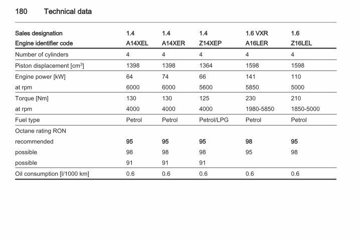
180 Technical data
Sales designation 1.4 1.4 1.4 1.61.6 VXREngine identifier code A14XEL A14XER Z14XEP Z16LELA16LER
Number of cylinders 4 4 4 44
Piston displacement [cm3] 1398 1398 1364 15981598
Engine power [kW] 64 74 66 110141
at rpm 6000 6000 5600 50005850
Torque [Nm] 130 130 125 210230
at rpm 4000 4000 4000 1850-50001980-5850
Fuel type Petrol Petrol Petrol/LPG PetrolPetrol
Octane rating RON
recommended 95 95 95 9598
possible 98 98 98 9895
possible 91 91 91
Oil consumption [l/1000 km] 0.6 0.6 0.6 0.60.6
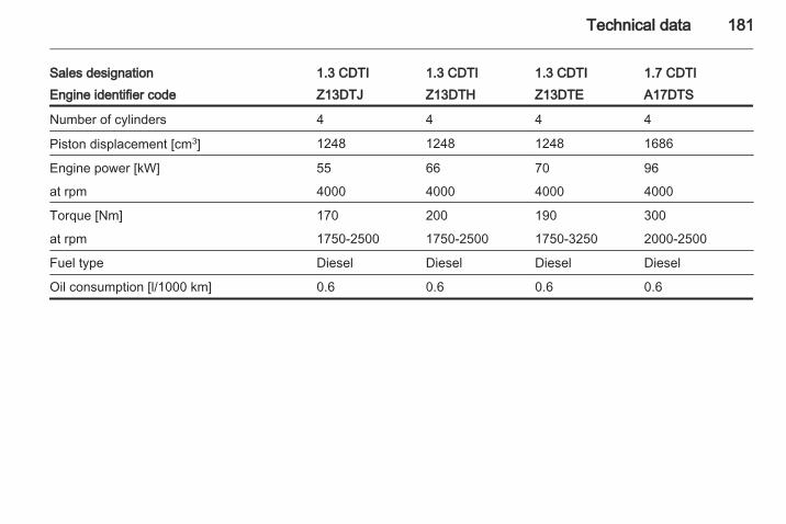
Technical data 181
Sales designation 1.3 CDTI 1.3 CDTI 1.3 CDTI 1.7 CDTIEngine identifier code Z13DTJ Z13DTH Z13DTE A17DTS
Number of cylinders 4 4 4 4
Piston displacement [cm3] 1248 1248 1248 1686
Engine power [kW] 55 66 70 96
at rpm 4000 4000 4000 4000
Torque [Nm] 170 200 190 300
at rpm 1750-2500 1750-2500 1750-3250 2000-2500
Fuel type Diesel Diesel Diesel Diesel
Oil consumption [l/1000 km] 0.6 0.6 0.6 0.6
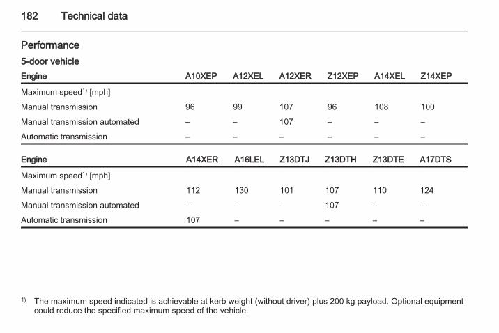
182 Technical data
Performance5-door vehicleEngine A10XEP A12XEL A12XER Z12XEP A14XEL Z14XEP
Maximum speed1) [mph]
Manual transmission 96 99 107 96 108 100
Manual transmission automated – – 107 – – –
Automatic transmission – – – – – –
Engine A14XER A16LEL Z13DTJ Z13DTH Z13DTE A17DTS
Maximum speed1) [mph]
Manual transmission 112 130 101 107 110 124
Manual transmission automated – – – 107 – –
Automatic transmission 107 – – – – –
1) The maximum speed indicated is achievable at kerb weight (without driver) plus 200 kg payload. Optional equipmentcould reduce the specified maximum speed of the vehicle.
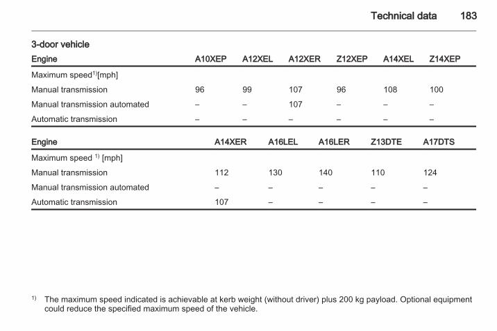
Technical data 183
3-door vehicleEngine A10XEP A12XEL A12XER Z12XEP A14XEL Z14XEP
Maximum speed1)[mph]
Manual transmission 96 99 107 96 108 100
Manual transmission automated – – 107 – – –
Automatic transmission – – – – – –
Engine A14XER A16LEL A16LER Z13DTE A17DTS
Maximum speed 1) [mph]
Manual transmission 112 130 140 110 124
Manual transmission automated – – – – –
Automatic transmission 107 – – – –
1) The maximum speed indicated is achievable at kerb weight (without driver) plus 200 kg payload. Optional equipmentcould reduce the specified maximum speed of the vehicle.
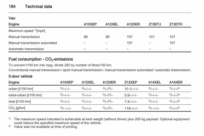
184 Technical data
VanEngine A10XEP A12XEL A12XER Z13DTJ Z13DTH
Maximum speed 1)[mph]
Manual transmission 96 99 107 101 107
Manual transmission automated – – 107 – 107
Automatic transmission – – – – –
Fuel consumption - CO2-emissionsTo convert l/100 km into mpg, divide 282 by number of litres/100 km.Conventional manual transmission / sport manual transmission / manual transmission automated / automatic transmission.
5-door vehicleEngine A10XEP A12XEL A12XER Z12XEP A14XEL A14XER
urban [l/100 km] 2)/–/–/– 2)/–/–/– 2)/–/2)/– 10.1/–/–/– 2)/–/–/– 2)/–/–/2)
extra-urban [l/100 km] 2)/–/–/– 2)/–/–/– 2)/–/2)/– 5.9/–/–/– 2)/–/–/– 2)/–/–/2)
total [l/100 km] 2)/–/–/– 2)/–/–/– 2)/–/2)/– 7.4/–/–/– 2)/–/–/– 2)/–/–/2)
CO2 [g/km] 2)/– /–/– 2)/–/–/– 2)/–/2)/– 119/–/–/– 2)/– /–/– 2)/–/–/2)
1) The maximum speed indicated is achievable at kerb weight (without driver) plus 200 kg payload. Optional equipmentcould reduce the specified maximum speed of the vehicle.
2) Value was not available at time of printing.
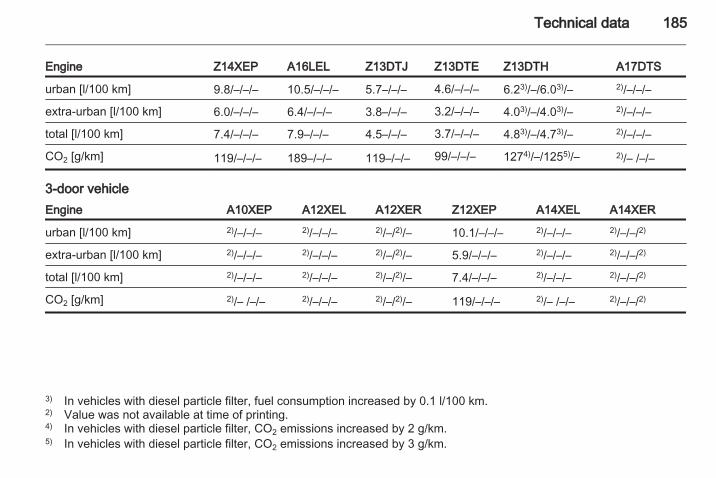
Technical data 185
Engine Z14XEP A16LEL Z13DTJ Z13DTE Z13DTH A17DTS
urban [l/100 km] 9.8/–/–/– 10.5/–/–/– 5.7–/–/– 4.6/–/–/– 6.23)/–/6.03)/– 2)/–/–/–
extra-urban [l/100 km] 6.0/–/–/– 6.4/–/–/– 3.8–/–/– 3.2/–/–/– 4.03)/–/4.03)/– 2)/–/–/–
total [l/100 km] 7.4/–/–/– 7.9–/–/– 4.5–/–/– 3.7/–/–/– 4.83)/–/4.73)/– 2)/–/–/–
CO2 [g/km] 119/–/–/– 189–/–/– 119–/–/– 99/–/–/– 1274)/–/1255)/– 2)/– /–/–
3-door vehicleEngine A10XEP A12XEL A12XER Z12XEP A14XEL A14XER
urban [l/100 km] 2)/–/–/– 2)/–/–/– 2)/–/2)/– 10.1/–/–/– 2)/–/–/– 2)/–/–/2)
extra-urban [l/100 km] 2)/–/–/– 2)/–/–/– 2)/–/2)/– 5.9/–/–/– 2)/–/–/– 2)/–/–/2)
total [l/100 km] 2)/–/–/– 2)/–/–/– 2)/–/2)/– 7.4/–/–/– 2)/–/–/– 2)/–/–/2)
CO2 [g/km] 2)/– /–/– 2)/–/–/– 2)/–/2)/– 119/–/–/– 2)/– /–/– 2)/–/–/2)
3) In vehicles with diesel particle filter, fuel consumption increased by 0.1 l/100 km.2) Value was not available at time of printing.4) In vehicles with diesel particle filter, CO2 emissions increased by 2 g/km.5) In vehicles with diesel particle filter, CO2 emissions increased by 3 g/km.
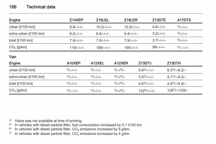
186 Technical data
Engine Z14XEP Z16LEL Z16LER Z13DTE A17DTS
urban [l/100 km] 9.8/–/–/– 10.5/–/–/– 10.5/–/–/– 4.6/–/–/– 2)/–/–/–
extra-urban [l/100 km] 6.0/–/–/– 6.4/–/–/– 6.4/–/–/– 3.2/–/–/– 2)/–/–/–
total [l/100 km] 7.4/–/–/– 7.9/–/–/– 7.9/–/–/– 3.7/–/–/– 2)/–/–/–
CO2 [g/km] 119/–/–/– 189/–/–/– 190/–/–/– 98/–/–/– 2)/– /–/–
VanEngine A10XEP A12XEL A12XER Z13DTJ Z13DTH
urban [l/100 km] 2)/–/–/– 2)/–/–/– 2)/–/2)/– 5.83)/–/–/– 6.33)/–/6.2/–
extra-urban [l/100 km] 2)/–/–/– 2)/–/–/– 2)/–/2)/– 3.93)/–/–/– 4.13)/–/4.2/–
total [l/100 km] 2)/–/–/– 2)/–/–/– 2)/–/2)/– 4.63)/–/–/– 4.93)/–/4.9/–
CO2 [g/km] 2)/– /–/– 2)/–/–/– 2)/–/2)/– 1226)/–/–/– 1297)/–/129/–
2) Value was not available at time of printing.3) In vehicles with diesel particle filter, fuel consumption increased by 0.1 l/100 km.6) In vehicles with diesel particle filter, CO2 emissions increased by 5 g/km.7) In vehicles with diesel particle filter, CO2 emissions increased by 4 g/km.
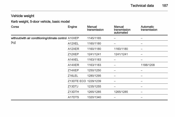
Technical data 187
Vehicle weightKerb weight, 5-door vehicle, basic modelCorsa Engine Manual
transmissionManualtransmissionautomated
Automatictransmission
without/with air conditioning/climate control[kg]
A10XEP 1145/1165 – –
A12XEL 1160/1180 – –
A12XER 1160/1180 1160/1180 –
Z12XEP 1241/1241 1241/1241 –
A14XEL 1163/1183 – –
A14XER 1163/1183 – 1188/1208
Z14XEP 1250/1250 – –
Z16LEL 1280/1295 – –
Z13DTE ECO 1229/1239 – –
Z13DTJ 1235/1255 – –
Z13DTH 1265/1285 1265/1285 –
A17DTS 1320/1340 – –
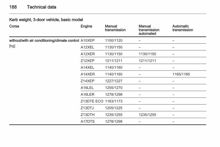
188 Technical data
Kerb weight, 3-door vehicle, basic modelCorsa Engine Manual
transmissionManualtransmissionautomated
Automatictransmission
without/with air conditioning/climate control[kg]
A10XEP 1100/1120 – –
A12XEL 1130/1150 – –
A12XER 1130/1150 1130/1150 –
Z12XEP 1211/1211 1211/1211 –
A14XEL 1140/1160 – –
A14XER 1140/1160 – 1165/1185
Z14XEP 1227/1227 – –
A16LEL 1255/1270 – –
A16LER 1278/1298 – –
Z13DTE ECO 1163/1173 – –
Z13DTJ 1205/1225 – –
Z13DTH 1235/1255 1235/1255 –
A17DTS 1278/1298 – –
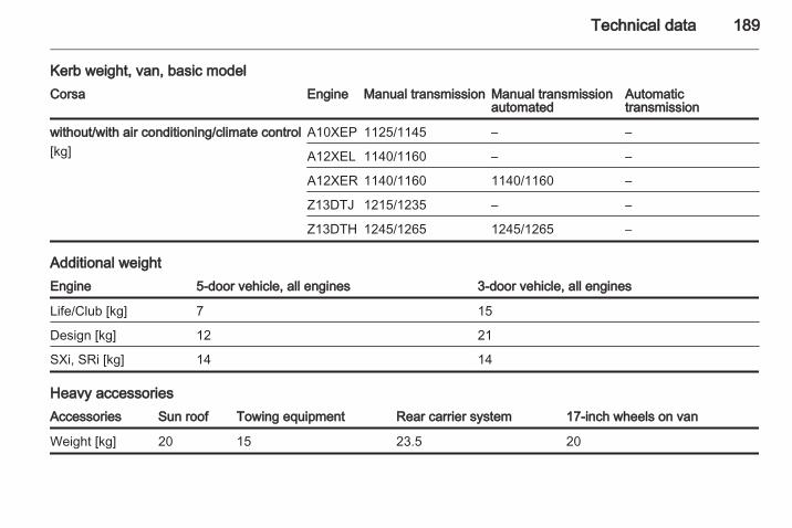
Technical data 189
Kerb weight, van, basic modelCorsa Engine Manual transmission Manual transmission
automatedAutomatictransmission
without/with air conditioning/climate control[kg]
A10XEP 1125/1145 – –
A12XEL 1140/1160 – –
A12XER 1140/1160 1140/1160 –
Z13DTJ 1215/1235 – –
Z13DTH 1245/1265 1245/1265 –
Additional weightEngine 5-door vehicle, all engines 3-door vehicle, all engines
Life/Club [kg] 7 15
Design [kg] 12 21
SXi, SRi [kg] 14 14
Heavy accessoriesAccessories Sun roof Towing equipment Rear carrier system 17-inch wheels on van
Weight [kg] 20 15 23.5 20
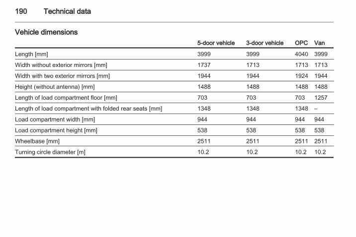
190 Technical data
Vehicle dimensions5-door vehicle 3-door vehicle OPC Van
Length [mm] 3999 3999 4040 3999
Width without exterior mirrors [mm] 1737 1713 1713 1713
Width with two exterior mirrors [mm] 1944 1944 1924 1944
Height (without antenna) [mm] 1488 1488 1488 1488
Length of load compartment floor [mm] 703 703 703 1257
Length of load compartment with folded rear seats [mm] 1348 1348 1348 –
Load compartment width [mm] 944 944 944 944
Load compartment height [mm] 538 538 538 538
Wheelbase [mm] 2511 2511 2511 2511
Turning circle diameter [m] 10.2 10.2 10.2 10.2
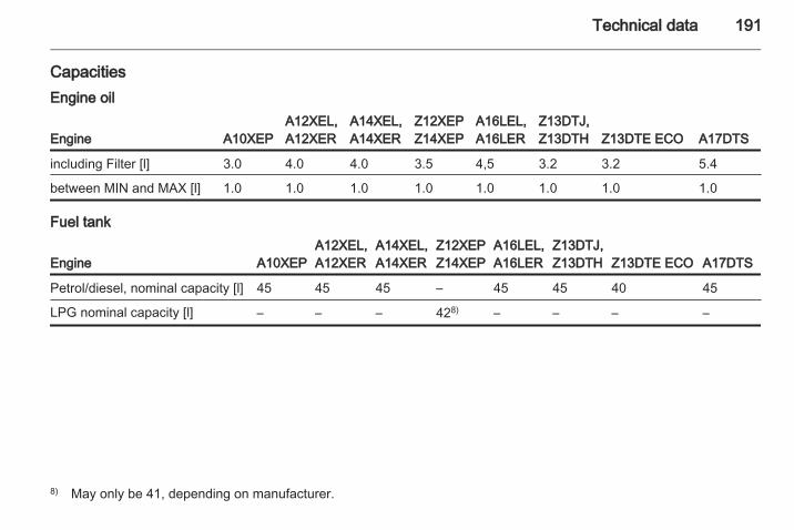
Technical data 191
CapacitiesEngine oil
Engine A10XEPA12XEL,A12XER
A14XEL,A14XER
Z12XEPZ14XEP
A16LEL,A16LER
Z13DTJ,Z13DTH Z13DTE ECO A17DTS
including Filter [l] 3.0 4.0 4.0 3.5 4,5 3.2 3.2 5.4
between MIN and MAX [l] 1.0 1.0 1.0 1.0 1.0 1.0 1.0 1.0
Fuel tank
Engine A10XEPA12XEL,A12XER
A14XEL,A14XER
Z12XEPZ14XEP
A16LEL,A16LER
Z13DTJ,Z13DTH Z13DTE ECO A17DTS
Petrol/diesel, nominal capacity [l] 45 45 45 – 45 45 40 45
LPG nominal capacity [l] – – – 428) – – – –
8) May only be 41, depending on manufacturer.
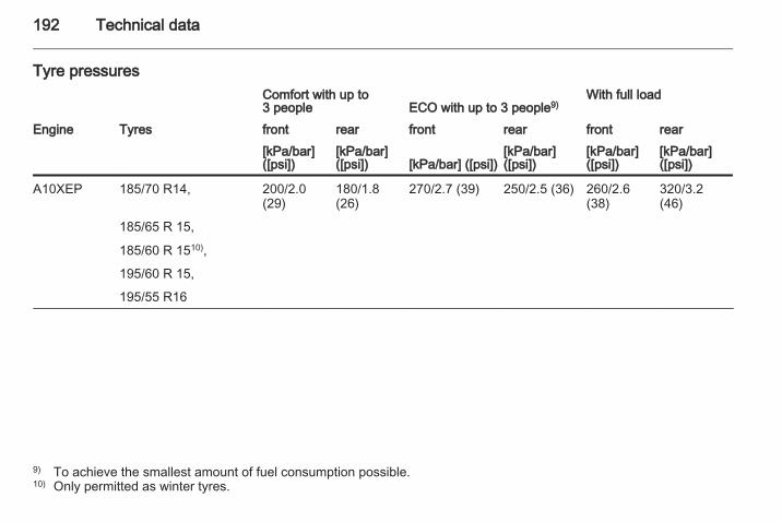
192 Technical data
Tyre pressuresComfort with up to3 people ECO with up to 3 people9)
With full load
Engine Tyres front rear front rear front rear[kPa/bar]([psi])
[kPa/bar]([psi]) [kPa/bar] ([psi])
[kPa/bar]([psi])
[kPa/bar]([psi])
[kPa/bar]([psi])
A10XEP 185/70 R14, 200/2.0(29)
180/1.8(26)
270/2.7 (39) 250/2.5 (36) 260/2.6(38)
320/3.2(46)
185/65 R 15,
185/60 R 1510),
195/60 R 15,
195/55 R16
9) To achieve the smallest amount of fuel consumption possible.10) Only permitted as winter tyres.
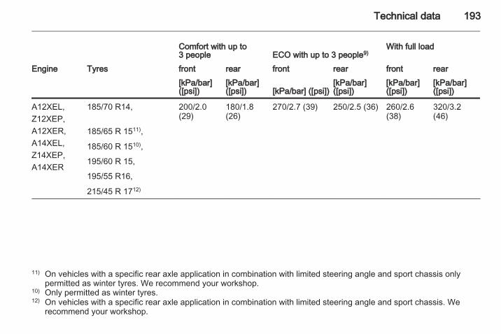
Technical data 193
Comfort with up to3 people ECO with up to 3 people9)
With full load
Engine Tyres front rear front rear front rear[kPa/bar]([psi])
[kPa/bar]([psi]) [kPa/bar] ([psi])
[kPa/bar]([psi])
[kPa/bar]([psi])
[kPa/bar]([psi])
A12XEL,Z12XEP,A12XER,A14XEL,Z14XEP,A14XER
185/70 R14, 200/2.0(29)
180/1.8(26)
270/2.7 (39) 250/2.5 (36) 260/2.6(38)
320/3.2(46)
185/65 R 1511),
185/60 R 1510),
195/60 R 15,
195/55 R16,
215/45 R 1712)
11) On vehicles with a specific rear axle application in combination with limited steering angle and sport chassis onlypermitted as winter tyres. We recommend your workshop.
10) Only permitted as winter tyres.12) On vehicles with a specific rear axle application in combination with limited steering angle and sport chassis. We
recommend your workshop.
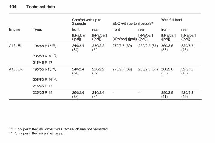
194 Technical data
Comfort with up to3 people ECO with up to 3 people9)
With full load
Engine Tyres front rear front rear front rear[kPa/bar]([psi])
[kPa/bar]([psi]) [kPa/bar] ([psi])
[kPa/bar]([psi])
[kPa/bar]([psi])
[kPa/bar]([psi])
A16LEL 195/55 R1613), 240/2.4(34)
220/2.2(32)
270/2.7 (39) 250/2.5 (36) 260/2.6(38)
320/3.2(46)
205/50 R 1610),
215/45 R 17
A16LER 195/55 R1613), 240/2.4(34)
220/2.2(32)
270/2.7 (39) 250/2.5 (36) 260/2.6(38)
320/3.2(46)
205/50 R 1610),
215/45 R 17
225/35 R 18 260/2.6(38)
240/2.4(34)
– – 280/2.8(41)
320/3.2(46)
13) Only permitted as winter tyres. Wheel chains not permitted.10) Only permitted as winter tyres.
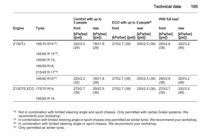
Technical data 195
Comfort with up to3 people ECO with up to 3 people9)
With full load
Engine Tyres front rear front rear front rear[kPa/bar]([psi])
[kPa/bar]([psi]) [kPa/bar] ([psi])
[kPa/bar]([psi])
[kPa/bar]([psi])
[kPa/bar]([psi])
Z13DTJ 185/70 R1414), 200/2.0(29)
180/1.8(26)
270/2.7 (39) 250/2.5 (36) 260/2.6(38)
320/3.2(46)
185/65 R 1515),
195/60 R 15,
195/55 R16,
215/45 R 1716)
185/60 R1510) 220/2.2(32)
180/1.8(26)
270/2.7 (39) 250/2.5 (36) 260/2.6(38)
320/3.2(46)
Z13DTE ECO 175/70 R14, 270/2.7(39)
250/2.5(36)
270/2.7 (39) 250/2.5 (36) 270/2.7(39)
320/3.2(46)
185/65 R 15
14) Not in combination with limited steering angle and sport chassis. Only permitted with certain brake systems. Werecommend your workshop.
15) In combination with limited steering angle or sport chassis only permitted as winter tyres. We recommend your workshop.16) In combination with limited steering angle or sport chassis. We recommend your workshop.10) Only permitted as winter tyres.
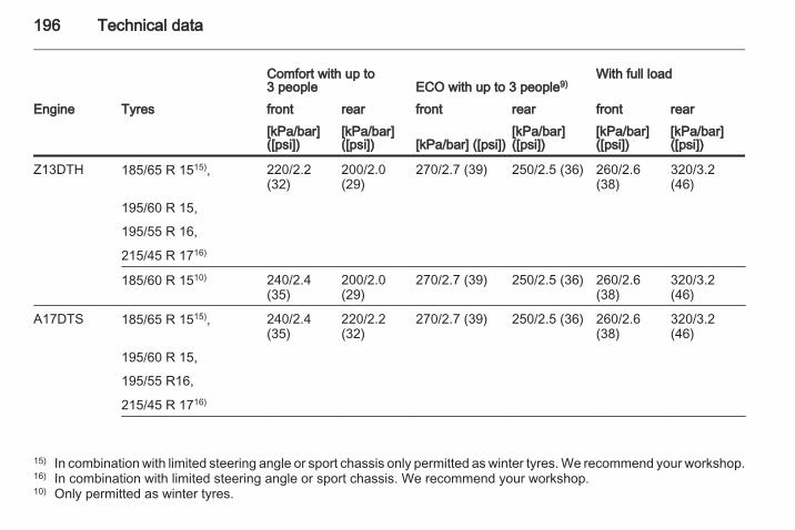
196 Technical data
Comfort with up to3 people ECO with up to 3 people9)
With full load
Engine Tyres front rear front rear front rear[kPa/bar]([psi])
[kPa/bar]([psi]) [kPa/bar] ([psi])
[kPa/bar]([psi])
[kPa/bar]([psi])
[kPa/bar]([psi])
Z13DTH 185/65 R 1515), 220/2.2(32)
200/2.0(29)
270/2.7 (39) 250/2.5 (36) 260/2.6(38)
320/3.2(46)
195/60 R 15,
195/55 R 16,
215/45 R 1716)
185/60 R 1510) 240/2.4(35)
200/2.0(29)
270/2.7 (39) 250/2.5 (36) 260/2.6(38)
320/3.2(46)
A17DTS 185/65 R 1515), 240/2.4(35)
220/2.2(32)
270/2.7 (39) 250/2.5 (36) 260/2.6(38)
320/3.2(46)
195/60 R 15,
195/55 R16,
215/45 R 1716)
15) In combination with limited steering angle or sport chassis only permitted as winter tyres. We recommend your workshop.16) In combination with limited steering angle or sport chassis. We recommend your workshop.10) Only permitted as winter tyres.
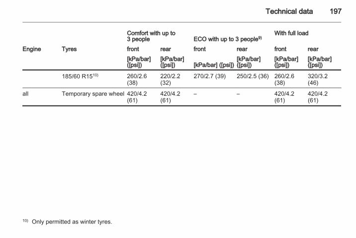
Technical data 197
Comfort with up to3 people ECO with up to 3 people9)
With full load
Engine Tyres front rear front rear front rear[kPa/bar]([psi])
[kPa/bar]([psi]) [kPa/bar] ([psi])
[kPa/bar]([psi])
[kPa/bar]([psi])
[kPa/bar]([psi])
185/60 R1510) 260/2.6(38)
220/2.2(32)
270/2.7 (39) 250/2.5 (36) 260/2.6(38)
320/3.2(46)
all Temporary spare wheel 420/4.2(61)
420/4.2(61)
– – 420/4.2(61)
420/4.2(61)
10) Only permitted as winter tyres.
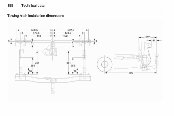
198 Technical data
Towing hitch installation dimensions
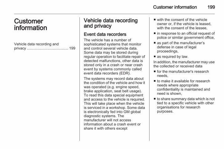
Customer information 199
Customerinformation
Vehicle data recording andprivacy ....................................... 199
Vehicle data recordingand privacyEvent data recordersThe vehicle has a number ofsophisticated systems that monitorand control several vehicle data.Some data may be stored duringregular operation to facilitate repair ofdetected malfunctions, other data isstored only in a crash or near crashevent by systems commonly calledevent data recorders (EDR).The systems may record data aboutthe condition of the vehicle and how itwas operated (e.g. engine speed,brake application, seat belt usage).To read this data special equipmentand access to the vehicle is required.This will take place when the vehicleis serviced in a workshop. Some datais electronically fed into GM globaldiagnostic systems. Themanufacturer will not accessinformation about a crash event orshare it with others except
■ with the consent of the vehicleowner or, if the vehicle is leased,with the consent of the lessee,
■ in response to an official request ofpolice or similar government office,
■ as part of the manufacturer’sdefense in case of legalproceedings,
■ as required by law.In addition, the manufacturer may usethe collected or received data■ for the manufacturer's research
needs,■ to make it available for research
needs where appropriateconfidentiality is maintained andneed is shown,
■ to share summary data which is nottied to a specific vehicle with otherorganisations for researchpurposes.
200
Index AAccessories and vehicle
modifications .......................... 134Adaptive forward lighting ..........
.................................... 80, 95, 143Adjustable air vents ................... 108Airbag and belt tensioners ........... 76Airbag deactivation ................ 42, 76Airbag system .............................. 38Air conditioning regular
operation ................................ 109Air conditioning system .............. 105Air intake .................................... 109Antilock brake system ................ 122Antilock brake system (ABS) ....... 77Anti-theft alarm system ................ 24Anti-theft locking system .............. 24Apply footbrake ............................ 80Ashtrays ....................................... 71Automatic anti-dazzle .................. 28Automatic light control ................. 93Automatic locking ........................ 23Automatic transmission ............. 114Auxiliary devices ........................ 102Auxiliary heater........................... 108
BBattery ....................................... 139Battery discharge protection ...... 100
Battery voltage ............................. 86Bonnet ....................................... 135Brake and clutch system ............. 77Brake assist ............................... 123Brake fluid .................................. 138Brake light switch ......................... 86Brakes ............................... 122, 138Bulb replacement ....................... 140
CCapacities .................................. 191Car Pass ...................................... 18Catalytic converter ..................... 113Central locking system ................ 20Centre console lighting ................ 99Changing tyre and wheel size . . . 160Charging system .......................... 76Child locks ................................... 23Child restraint installation
locations ................................... 45Child restraint systems ................ 43Cigarette lighter ........................... 71Climate control ............................. 14Clock ............................................ 70Control indicators.......................... 74Control of the vehicle ................. 110Convex shape .............................. 26Cruise control ...................... 81, 124Cupholders .................................. 49Curtain airbag system .................. 41
201
DDanger, Warnings and Cautions . . . 4Deflation detection system........... 79Diesel fuel system bleeding ....... 139Diesel particle filter .................... 112Drain diesel fuel filter ................... 86Driving characteristics and
towing tips .............................. 129
EEasytronic................................... 118Electric adjustment ...................... 26Electronic climate control
system .................................... 106Electronic driving programmes .
........................................ 115, 119Electronic Stability Program 78, 123End-of-life vehicle recovery ....... 135Engine compartment fuse box ... 153Engine coolant ........................... 137Engine coolant temperature ........ 78Engine data ............................... 179Engine exhaust .......................... 112Engine oil ................................... 136Engine oil pressure ...................... 79Entry lighting ................................ 99Event data recorders.................. 199Exit lighting ................................ 100Exterior care .............................. 170
Exterior light ................................. 80Exterior lighting ............................ 11
FFault ................................... 116, 121First aid kit ................................... 63Fixed air vents ........................... 109Fog light ....................................... 80Fog lights ................................... 146Folding ......................................... 26Front airbag system ..................... 39Front fog lights ............................. 96Front turn signal lights ............... 146Fuel consumption - CO2-
Emissions ....................... 128, 184Fuel for diesel engines .............. 126Fuel for petrol engines ............... 126Fuel gauge ................................... 73Fuses ......................................... 152
GGeneral information ................... 129Glovebox ..................................... 49Graphic-Info-Display, Colour-
Info-Display .............................. 81
HHalogen headlights .................... 141Hand brake................................. 123Hazard warning flashers .............. 96
Headlight flash ............................. 94Headlight range adjustment ........ 94Headlights when driving abroad . . 94Head restraint adjustment ............. 7Head restraints ............................ 32Heated ......................................... 27Heated rear window ..................... 30Heated steering wheel ................. 67Heating ........................................ 35Heating and ventilation system . 104High beam ............................. 80, 94Hill start assist ........................... 123Horn ....................................... 13, 67
IIdentification plate ..................... 177Ignition switch positions ............. 111Immobiliser .................................. 25Instrument cluster ........................ 72Instrument panel fuse box ......... 154Instrument panel illumination
control ...................................... 98Instrument panel overview ........... 11Interior care ............................... 171Interior lights ........................ 98, 151Interruption of power supply .....
........................................ 116, 121Introduction .................................... 3Isofix child restraint systems ........ 48
202
JJump starting ............................. 166
KKeys ............................................. 18
LLashing eyes ............................... 62Lighting ........................................ 86Light switch .................................. 93Load compartment ................ 23, 58Load compartment cover ............. 60Load compartment fuse box ...... 155Load compartment lighting........... 99Loading information ..................... 64Low engine oil level ..................... 80Low fuel ....................................... 80
MMalfunction indicator light ............ 77Manual anti-dazzle ...................... 28Manual mode ............................. 119Manual transmission .................. 117Manual transmission automated 118Manual windows .......................... 28Memorised settings...................... 20Mirror adjustment ........................... 8Misted light covers ....................... 97Mobile phones and CB radio
equipment .............................. 102
NNew vehicle running-in .............. 110Number plate light ..................... 150
OOdometer ..................................... 72Operation ................................... 101Outside temperature .................... 69Overrun cut-off ........................... 111
PParking ................................ 16, 111Parking assist ............................ 125Parking brake ............................ 123Parking lights ............................... 97Particle filter................................ 112Performance .............................. 182Performing work ........................ 135Pollen filter ................................. 109Power outlets ............................... 70Power steering.............................. 78Power windows ............................ 29Preheating and diesel particle
filter .......................................... 79
QQuickheat................................... 108
RRadio reception ......................... 101Radio remote control ................... 19Reading lights .............................. 99Rear carrier system...................... 50Rear floor storage cover .............. 61Rear fog light ............................... 80Rear fog lights ............................. 97Rear window wiper/washer .......... 69Recommended fluids and
lubricants ................................ 174Refuelling ................................... 127Reversing lights ........................... 97Roof rack ..................................... 63
SSeat adjustment ....................... 6, 34Seat belt ........................................ 8Seat belt reminder ....................... 76Seat belts ..................................... 36Seat folding .................................. 35Seat position ................................ 33Selector lever ..................... 114, 118Service ............................... 109, 173Service display ............................ 73Service information .................... 173Service vehicle soon .................... 77Side airbag system ...................... 40Side turn signal lights ................ 150
203
Spare wheel ............................... 165Speedometer ............................... 72Sport mode .................................. 78Starting off ................................... 16Starting the engine ............ 111, 118Steering wheel adjustment ...... 9, 66Steering wheel controls ............... 66Stop watch ................................... 90Sunroof ........................................ 30Sun visors .................................... 30Symbols ......................................... 4
TTachometer ................................. 72Tail lights ................................... 146Three-point seat belt .................... 37Tools .......................................... 156Top-tether child restraint
systems .................................... 48Towing another vehicle ............. 169Towing equipment ..................... 130Towing hitch installation
dimensions ............................. 198Towing the vehicle ..................... 168Trailer towing ............................. 129Transmission ............................... 15Transmission display ... 73, 114, 118Tread depth ............................... 159Trip computer .............................. 87
Trip computer in Graphic-Info-Display or Colour-Info-Display . 88
Triple-Info-Display ....................... 81Trip odometer .............................. 72Turn and lane-change signals ..... 96Turn signal ................................... 76Tyre chains ................................ 160Tyre deflation detection system . 159Tyre designations ...................... 158Tyre pressure ............................ 158Tyre pressures ........................... 192Tyre repair kit ............................. 160Tyres .......................................... 157
UUltrasonic parking assist .............. 78Underseat storage ....................... 50Upshift.......................................... 78Using this manual .......................... 3
VVehicle dimensions .................... 190Vehicle Identification Number .... 177Vehicle messages ....................... 85Vehicle personalisation ............... 91Vehicle specific data ...................... 3Vehicle storage........................... 134Vehicle unlocking ........................... 6Vehicle weight ........................... 187Ventilation................................... 104
WWarning chimes ........................... 85Warning triangle .......................... 62Washer and wiper systems ......... 13Washer fluid ............................... 138Wheel changing ......................... 163Wheel covers ............................. 160Wheels and tyres ....................... 157Windscreen wiper/washer ........... 68Winter mode ................................ 78Winter tyres ............................... 158Wiper blade replacement .......... 139

204


