Embed Size (px)
Citation preview

1University Program Material
Copyright © ARM Ltd 2012
Cortex-M4 Processor Overview
with ARM Processors and Architectures

2University Program Material
Copyright © ARM Ltd 2012
Introduction

3University Program Material
Copyright © ARM Ltd 2012
ARM
ARM was developed at Acorn Computer Limited of Cambridge, UK (between
1983 & 1985)
RISC concept introduced in 1980 at Stanford and Berkeley
ARM founded in November 1990
Advanced RISC Machines
Best known for its range of RISC processor cores designs
Other products – fabric IP, software tools, models, cell libraries - to help partners
develop and ship ARM-based SoCs
ARM does not manufacture silicon
Licensed to partners to develop and fabricate new micro-controllers
Soft-core

4University Program Material
Copyright © ARM Ltd 2012
ARM Architecture
Based upon RISC Architecture with enhancements to meet requirements of
embedded applications
A large uniform register file
Load-store architecture
Fixed length instructions
32-bit processor (v1-v7), 64-bit processor (v8)
Good speed/power
High code density

5University Program Material
Copyright © ARM Ltd 2012
Enhancement to Basic RISC
Control over both ALU and shifter for every data processing operations
Auto-increment and auto-decrement addressing modes
To optimize program loops
Load/Store multiple data instructions
To maximize data throughput
Conditional execution of instructions
To maximize execution throughput

6University Program Material
Copyright © ARM Ltd 2012
Embedded Processors

7University Program Material
Copyright © ARM Ltd 2012
Application Processors
8University Program Material
Copyright © ARM Ltd 2012
ARM Processor Family

9University Program Material
Copyright © ARM Ltd 2012
Summary of Processor Characteristics

10University Program Material
Copyright © ARM Ltd 2012
ARM Architecture Overview

11University Program Material
Copyright © ARM Ltd 2012
Architecture History

12University Program Material
Copyright © ARM Ltd 2012
Halfword and
signed halfword
/ byte support
System mode
Thumb
instruction set
(v4T)
Improved
interworking
CLZ
Saturated arithmetic
DSP MAC
instructions
Extensions:
Jazelle (5TEJ)
SIMD Instructions
Multi-processing
v6 Memory architecture
Unaligned data support
Extensions:
Thumb-2 (6T2)
TrustZone® (6Z)
Multicore (6K)
Thumb only (6-M)
Note that implementations of the same architecture can be different
Cortex-A8 - architecture v7-A, with a 13-stage pipeline
Cortex-A9 - architecture v7-A, with an 8-stage pipeline
Thumb-2
Architecture Profiles
7-A - Applications
7-R - Real-time
7-M - Microcontroller
v4 v5 v6 v7
Development of the ARM Architecture
13University Program Material
Copyright © ARM Ltd 2012
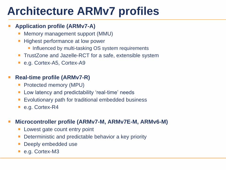
Architecture ARMv7 profiles
Application profile (ARMv7-A)
Memory management support (MMU)
Highest performance at low power
Influenced by multi-tasking OS system requirements
TrustZone and Jazelle-RCT for a safe, extensible system
e.g. Cortex-A5, Cortex-A9
Real-time profile (ARMv7-R)
Protected memory (MPU)
Low latency and predictability ‘real-time’ needs
Evolutionary path for traditional embedded business
e.g. Cortex-R4
Microcontroller profile (ARMv7-M, ARMv7E-M, ARMv6-M)
Lowest gate count entry point
Deterministic and predictable behavior a key priority
Deeply embedded use
e.g. Cortex-M3

14University Program Material
Copyright © ARM Ltd 2012
Which architecture is my processor?

15University Program Material
Copyright © ARM Ltd 2012
Cotex-M Processor Family

16University Program Material
Copyright © ARM Ltd 2012
ARMv7-M Architecture

17University Program Material
Copyright © ARM Ltd 2012
ARMv7-M Profile Overview
v7-M Cores are designed to support the microcontroller market
Simpler to program – entire application can be programmed in C
Fewer features needed than in application processors
Register and ISA changes from other ARM cores
No ARM instruction set support
Only one set of registers
xPSR has different bits than CPSR
Different modes and exception models
Only two modes: Thread mode and Handler mode
Vector table is addresses, not instructions
Exceptions automatically save state (r0-r3, r12, lr, xPSR, pc) on the stack
Different system control/memory layout
Cores have a fixed memory map
No coprocessor 15 – controlled through memory mapped control registers

18University Program Material
Copyright © ARM Ltd 2012
Cortex-M3
Cortex M3 Total
60k* Gates
ARMv7-M Architecture
Thumb-2 only
Fully programmable in C
3-stage pipeline
von Neumann architecture
Optional MPU
AHB-Lite bus interface
Fixed memory map
1-240 interrupts
Configurable priority levels
Non-Maskable Interrupt support
Debug and Sleep control
Serial wire or JTAG debug
Optional ETM

19University Program Material
Copyright © ARM Ltd 2012
Cortex-M0
Cortex M3 Total
60k* Gates
ARMv6-M Architecture
16-bit Thumb-2 with system control
instructions
Fully programmable in C
3-stage pipeline
von Neuman architecture
AHB-Lite bus interface
Fixed memory map
1-32 interrupts
Configurable priority levels
Non-Maskable Interrupt support
Low power support
Core configured with or without
debug
Variable number of watchpoints and
breakpoints

20University Program Material
Copyright © ARM Ltd 2012
Programmer’s Model

21University Program Material
Copyright © ARM Ltd 2012
Processor Register Set
Registers R0-R12
General-purpose registers
R13 is the stack pointer (SP) - 2 banked versions
R14 is the link register (LR)
R15 is the program counter (PC)
PSR (Program Status Register)
Not explicitly accessible
Saved to the stack on an exception
Subsets available as APSR, IPSR, and EPSR
R0
R1
R2
R3
R4
R5
R6
R7
R8
R9
R10
R11
R12
R15 (PC)
PSR
R13 (SP)
R14 (LR)

22University Program Material
Copyright © ARM Ltd 2012
Special Purpose Registers
Program Status Register
Described in upcoming slides
Special Purpose Mask Registers : PRIMASK, FAULTMASK, BASEPRI
Used to modify exception priorities
To set/clear PRIMASK and FAULTMASK, use CPS instructions
CPSIE i / CPSID i / CPSIE f / CPSID f
Special Purpose CONTROL Register
2 bits
Bit 0 defines Thread mode privilege
Bit 1 defines Thread mode stack
The Special Purpose Registers are not memory-mapped
Accessed via specific instructions
MRS – Move special purpose register to general-purpose register
MSR – Move general-purpose register to special purpose register

23University Program Material
Copyright © ARM Ltd 2012
xPSR - Program Status Register
xPSR stored on stack during exceptions
Condition code flags
N = Negative result from ALU
Z = Zero result from ALU
C = ALU operation carry out
V = ALU operation overflow
Q = Saturated math overflow
IT/ICI bits
Contain IF-THEN base condition code or Interrupt Continue information
ISR Number
Stacked xPSR shows which exception was pre-empted
T=1
IT/ICIIT
2731
N Z C V Q
28 8
ISR Number
1623 15 0242526 10
T
19
GE[3:0]
20 9

24University Program Material
Copyright © ARM Ltd 2012
System Timer – SysTick
Flexible system timer
24-bit self-reloading down counter
Reload on count == 0
Optionally cause SysTick interrupt on count == 0
Reload register
Calibration value
Clock source is CPU clock or optional external timing reference
Software selectable if provided
Reference pulse widths High/Low must exceed processor clock period
Counted by sampling on processor clock
Calibration Register provides value required for 10ms interval
STCALIB inputs tied to appropriate value

25University Program Material
Copyright © ARM Ltd 2012
Modes Overview
ARM Processor
Application Code
ThreadMode
Exception Code
HandlerMode
Exception
EntryException
Return
Reset
Not shown: Handler mode can also be re-entered on exception return

26University Program Material
Copyright © ARM Ltd 2012
Instruction Set Examples:
Data Processing:
MOV r2, r5 ; r2 = r5
ADD r5, #0x24 ; r5 = r5 + 36
ADD r2, r3, r4, LSL #2 ; r2 = r3 + (r4 * 4)
LSL r2, #3 ; r2 = r2 * 8
MOVT r9, #0x1234 ; upper halfword of r9 = #0x1234
MLA r0, r1, r2, r3 ; r0 = (r1 * r2) + r3
Memory Access:
STRB r2, [r10, r1] ; store lower byte in r2 at
address {r10 + r1}
LDR r0, [r1, r2, LSL #2] ; load r0 with data at address
{r1 + r2 * 4}
Program Flow:
BL <label> ; PC relative branch to <label>
location, and return address
stored in LR (r14)

27University Program Material
Copyright © ARM Ltd 2012
Exception Handling
Exception types:
Reset
Non-maskable Interrupts (NMI)
Faults
PendSV
SVCall
External Interrupt
SysTick Interrupt
Exceptions processed in Handler mode (except Reset)
Exceptions always run privileged
Interrupt handling
Interrupts are a sub-class of exception
Automatic save and restore of processor registers (xPSR, PC, LR, R12, R3-R0)
Allows handler to be written entirely in ‘C’

28University Program Material
Copyright © ARM Ltd 2012
External Interrupts
External Interrupts handled by Nested Vectored Interrupt Controller (NVIC)
Tightly coupled with processor core
One Non-Maskable Interrupt (NMI) supported
Number of external interrupts is implementation-defined
ARMv7-M supports up to 496 interrupts
……
Cortex-Mx
Processor Core
INTISR[0]
…
…
INTISR[N]
INTNMI
NVIC
Cortex-Mx Integration Layer

29University Program Material
Copyright © ARM Ltd 2012
Exception Handling Example
Core Execution
Higher Priority
Base CPU
IRQ2
IRQ1
Foreground ISR2 ISR1 ISR2 Foreground
Time
IRQ3
ISR3
(ISR 2 resumes)

30University Program Material
Copyright © ARM Ltd 2012
Vector Table for ARMv7-M First entry contains initial Main SP
All other entries are addresses for exception handlers
Must always have LSBit = 1 (for Thumb)
Table has up to 496 external interrupts
Implementation-defined
Maximum table size is 2048 bytes
Table may be relocated
Use Vector Table Offset Register
Still require minimal table entries at 0x0 for booting the core
Each exception has a vector number
Used in Interrupt Control and State Register to indicate the active or pending exception type
Table can be generated using C code
Example provided later
Reserved (x4)
Usage Fault
Mem Manage Fault
Hard Fault
NMI
Reset
Initial Main SP
0x1C to 0x28
0x18
0x14
0x10
0x0C
0x08
0x04
0x00
16 + N
…
16
15
14
13
12
11SVC
Debug Monitor
Reserved
PendSV
SysTick
External 0
Bus Fault
…
External N0x40 + 4*N
…
0x40
0x3C
0x38
0x34
0x30
0x2C
7-10
6
5
4
3
2
1
N/A
Address Vector #

31University Program Material
Copyright © ARM Ltd 2012
Reset Behavior
1. A reset occurs (Reset input was asserted)
2. Load MSP (Main Stack Pointer) register initial value from address 0x00
3. Load reset handler vector address from address 0x04
4. Reset handler executes in Thread Mode
5. Optional: Reset handler branches to the main program
0x04
0x001
Reset Handler
Initial value of MSP
Reset Handler Vector
r13 (MSP)
2
4
3
Main
5

32University Program Material
Copyright © ARM Ltd 2012
Exception Behaviour
1. Exception occurs
Current instruction stream stops
Processor accesses vector table
2. Vector address for the exception loaded from the vector table
3. Exception handler executes in Handler Mode
4. Exception handler returns to main
Exception Handler
Exception Vector
2
3
Main
1
4

33University Program Material
Copyright © ARM Ltd 2012
Interrupt Service Routine Entry When receiving an interrupt the processor will finish the current instruction
for most instructions
To minimize interrupt latency, the processor can take an interrupt during the
execution of a multi-cycle instruction - see next slide
Processor state automatically saved to the current stack
8 registers are pushed: PC, R0-R3, R12, LR, xPSR
Follows ARM Architecture Procedure Calling Standard (AAPCS)
During (or after) state saving the address of the ISR is read from the Vector Table
Link Register is modified for interrupt return
First instruction of ISR executed
For Cortex-M3 or Cortex-M4 the total latency is normally 12 cycles, however,
interrupt late-arrival and interrupt tail-chaining can improve IRQ latency
ISR executes from Handler mode with Main stack

34University Program Material
Copyright © ARM Ltd 2012
Returning From Interrupt
Can return from interrupt with the following instructions when the PC is loaded with “magic” value of 0xFFFF_FFFX (same format as EXC_RETURN)
LDR PC, …..
LDM/POP which includes loading the PC
BX LR (most common)
If no interrupts are pending, foreground state is restored
Stack and state specified by EXC_RETURN is used
Context restore on Cortex-M3 and Cortex-M4 requires 10 cycles
If other interrupts are pending, the highest priority may be serviced
Serviced if interrupt priority is higher than the foreground’s base priority
Process is called Tail-Chaining as foreground state is not yet restored
Latency for servicing new interrupt is only 6 cycles on M3/M4 (state already saved)
If state restore is interrupted, it is abandoned
New ISR executed without state saving (original state still intact and valid)
Must still fetch new vector and refill pipeline (6-cycle latency on M3/M4)

35University Program Material
Copyright © ARM Ltd 2012
The vector table at address
0x0 is minimally required to
have 4 values: stack top,
reset routine location,
NMI ISR location,
HardFault ISR location
Vector Table in C
Once interrupts are
enabled, the vector
table (whether at 0
or in SRAM) must
then have pointers
to all enabled (by
mask) exceptions
The SVCall ISR
location must be
populated if the SVC
instruction will be
used
typedef void(* const ExecFuncPtr)(void) __irq;
#pragma arm section rodata="exceptions_area”
ExecFuncPtr exception_table[] = {
(ExecFuncPtr)&Image$$ARM_LIB_STACK$$ZI$$Limit, /* Initial SP */
(ExecFuncPtr)__main, /* Initial PC */
NMIException,
HardFaultException,
MemManageException,
BusFaultException,
UsageFaultException,
0, 0, 0, 0, /* Reserved */
SVCHandler,
DebugMonitor,
0, /* Reserved */
PendSVC,
SysTickHandler
/* Configurable interrupts start here...*/
};
#pragma arm section

36University Program Material
Copyright © ARM Ltd 2012
Vector Table in AssemblyPRESERVE8
THUMB
IMPORT ||Image$$ARM_LIB_STACK$$ZI$$Limit||
AREA RESET, DATA, READONLY
EXPORT __Vectors
__Vectors DCD ||Image$$ARM_LIB_STACK$$ZI$$Limit|| ; Top of Stack
DCD Reset_Handler ; Reset Handler
DCD NMI_Handler ; NMI Handler
DCD HardFault_Handler ; Hard Fault Handler
DCD MemManage_Handler ; MemManage Fault Handler
DCD BusFault_Handler ; Bus Fault Handler
DCD UsageFault_Handler ; Usage Fault Handler
DCD 0, 0, 0, 0, ; Reserved x4
DCD SVC_Handler, ; SVCall Handler
DCD Debug_Monitor ; Debug Monitor Handler
DCD 0 ; Reserved
DCD PendSV_Handler ; PendSV Handler
DCD SysTick_Handler ; SysTick Handler
; External vectors start here

37University Program Material
Copyright © ARM Ltd 2012
Memory Systems

38University Program Material
Copyright © ARM Ltd 2012
Processor Memory Map
Code
SRAM
System
Peripheral
External Peripheral
External SRAM
FFFF_FFFF
2000_0000
4000_0000
6000_0000
A000_0000
E000_0000
0000_0000
512MB
1GB
1 GB
512MB
512MB
512MB
ITM
Internal Private Peripheral Bus
E000_E000
E000_3000
E000_2000
E000_1000
E000_0000
E000_F000
E00F_F000
E004_2000
E004_1000
E004_0000
E00F_FFFF
External Private Peripheral Bus
DWT
FPB
NVIC
RESERVED
RESERVED
UNUSED
TPIU
ETM
ROM Table
E003_FFFF
(XN)

39University Program Material
Copyright © ARM Ltd 2012
Memory Types and Properties
There are 3 different memory types:
Normal, Device and Strongly Ordered
Normal memory is the most flexible memory type:
Suitable for different types of memory, for example, ROM, RAM, Flash and SDRAM
Accesses may be restarted
Caches and Write Buffers are permitted to work alongside Normal memory
Device memory is suitable for peripherals and I/O devices
Caches are not permitted, but write buffers are still supported
Unaligned accesses are unpredictable
Accesses must not be restarted
Load/store multiple instructions should not be used to access Device memory
Strongly ordered memory is similar to Device memory
Buffers are not supported and the PPB is marked Strongly Ordered

40University Program Material
Copyright © ARM Ltd 2012
System Control Block
Memory mapped space containing registers to configure, control, and deal
with interrupts, exceptions, and debug
Replaces co-processor #15 in older ARM cores
Application Interrupt/Reset Control
Register
Bits[10:8] = 000Read/Write0xE000ED0C
Vector Table Offset Register0x00000000Read/Write0xE000ED08
Interrupt Control State Register0x00000000Read/Write0xE000ED04
CPUID Base RegisterIMP DEFINEDRead Only0xE000ED00
Interrupt Controller Type RegisterIMP DEFINEDRead Only0xE000E004
Master Control register - RESERVED0x00000000Read/Write0xE000E000
FunctionReset ValueTypeAddress

41University Program Material
Copyright © ARM Ltd 2012
More SCB Registers
Software Trigger Interrupt RegisterWrite Only0xE000EF00
Auxiliary Fault Status Register (vendor specific)UnpredictableRead/Write0xE000ED3C
BusFault Address RegisterUnpredictableRead/Write0xE000ED38
MemManage Address Register UnpredictableRead/Write0xE000ED34
DebugFault Status Registern/a - statusRead/Write0xE000ED30
HardFault Status Registern/a - statusRead/Write0xE000ED2C
Configurable Fault Status Registers (3)n/a - statusRead/Write0xE000ED28
System Handler Control and State Register0x00000000Read/Write0xE000ED24
System Handlers 12-15 Priority Register0x00000000Read/Write0xE000ED20
System Handlers 8-11 Priority Register0x00000000Read/Write0xE000ED1C
System Handlers 4-7 Priority Register0x00000000Read/Write0xE000ED18
Configuration Control Register0x00000000Read/Write0xE000ED14
System Control Register0x00000000Read/Write0xE000ED10
FunctionReset ValueTypeAddress

42University Program Material
Copyright © ARM Ltd 2012
Floating Point Extensions

43University Program Material
Copyright © ARM Ltd 2012
Cortex-M4
Cortex M3 Total
60k* Gates
ARMv7E-M Architecture
Thumb-2 only
DSP extensions
Optional FPU (Cortex-M4F)
Otherwise, same as Cortex-M3
Implements full Thumb-2
instruction set
Saturated math (e.g. QADD)
Packing and unpacking (e.g. UXTB)
Signed multiply (e.g. SMULTB)
SIMD (e.g. ADD8)

44University Program Material
Copyright © ARM Ltd 2012
Cortex-M4F Floating Point Registers
FPU provides a further 32 single-precision registers
Can be viewed as either
32 x 32-bit registers
16 x 64-bit doubleword registers
Any combination of the above
S31
S30
S29
S28
S3
S2
S1
S0
S7
S6
S5
S4
~~
~~
D15
D14
D1
D0
D3
D2
~~
~~

45University Program Material
Copyright © ARM Ltd 2012
Binary Upwards Compatibility
ARMv6-M
Architecture
ARMv7-M
Architecture
46University Program Material
Copyright © ARM Ltd 2012
ARM System Design

47University Program Material
Copyright © ARM Ltd 2012
On chip
memory
Example ARM-based system
ARM
Processor
core
AM
BA
AX
I External
Memory
Interface
APB
Bridge
AM
BA
AP
B
CoreLink
Interrupt
Controller
Other
CoreLink
Peripherals
DMA
PortClocks and
Reset Controller
ARM core deeply embedded within an
SoC
External debug and trace via JTAG or
CoreSight interface
Design can have both external and
internal memories
Varying width, speed and size –
depending on system requirements
Can include ARM licensed CoreLink
peripherals
Interrupt controller, since core only has
two interrupt sources
Other peripherals and interfaces
Can include on-chip memory from
ARM Artisan Physical IP Libraries
Elements connected using AMBA
(Advanced Microcontroller Bus
Architecture)
DEBUG
nIRQ
nFIQ
FLASH
SDRAM
ARM based
SoC
Custom
Peripherals

48University Program Material
Copyright © ARM Ltd 2012
High Performance
ARM processor
High-bandwidth
on-chip RAM
High
Bandwidth
External
Memory
Interface
DMA
Bus Master
APB
Bridge
Timer
Keypad
UART
PIO
AHB
APB
High Performance
Pipelined
Burst Support
Multiple Bus Masters
Low Power
Non-pipelined
Simple Interface
An Example AMBA System

49University Program Material
Copyright © ARM Ltd 2012
STM32 32-bit ARM Cortex MCUs

High-performance Cortex™-M4 MCU
STM32 F4 series

32-bit multi-AHB bus matrix
Real-time performance
Compressed
audio stream
(MP3) to 16kByte
SRAM block
MP3 decoder
code execution
by core
Access to the MP3
data for
decompression
Decompressed
audio stream to
112kByte SRAM
block
DMA transfer to
audio output
stage (I2S)
User interface:
DMA transfers of
the graphical
icons from Flash
to display

STM32 F4 series
High-performance digital signal controller
Single precision
Ease of use
Better code efficiency
Faster time to market
Eliminate scaling and saturation
Easier support for meta-language tools
FPU
Harvard architecture
Single-cycle MAC
Barrel shifter
DSP
Ease of use of C
programming
Interrupt handling
Ultra-low power
MCU
Cortex-M4
What is Cortex-M4?

STM32 product series
4 product series

STM32 F4 block diagram
Feature highlight
168 MHz Cortex-M4 CPU
Floating point unit (FPU)
ART Accelerator TM
Multi-level AHB bus matrix
1-Mbyte Flash, 192-Kbyte SRAM
1.7 to 3.6 V supply
RTC: <1 µA typ, sub second accuracy
2x full duplex I²S
3x 12-bit ADC 0.41 µs/2.4 MSPS
168 MHz timers


![Chapter5 1.ppt [호환 모드] - Hanyangccrs.hanyang.ac.kr/webpage_limdj/robust/Chapter5_1.pdf · SISO Nyquist Stability Citerion • A SISO is internally stable if all the zeros](https://img.pdfslide.net/doc/110x75/5e80a6c30c204c535a3bed8b/chapter5-1ppt-eeoe-siso-nyquist-stability-citerion-a-a-siso-is-internally.jpg)