Embed Size (px)
Citation preview
COS2014IA-32 Processor
Architecture
2
Overview
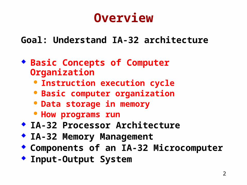
Goal: Understand IA-32 architecture
Basic Concepts of Computer Organization Instruction execution cycle Basic computer organization Data storage in memory How programs run
IA-32 Processor Architecture IA-32 Memory Management Components of an IA-32 Microcomputer Input-Output System
3
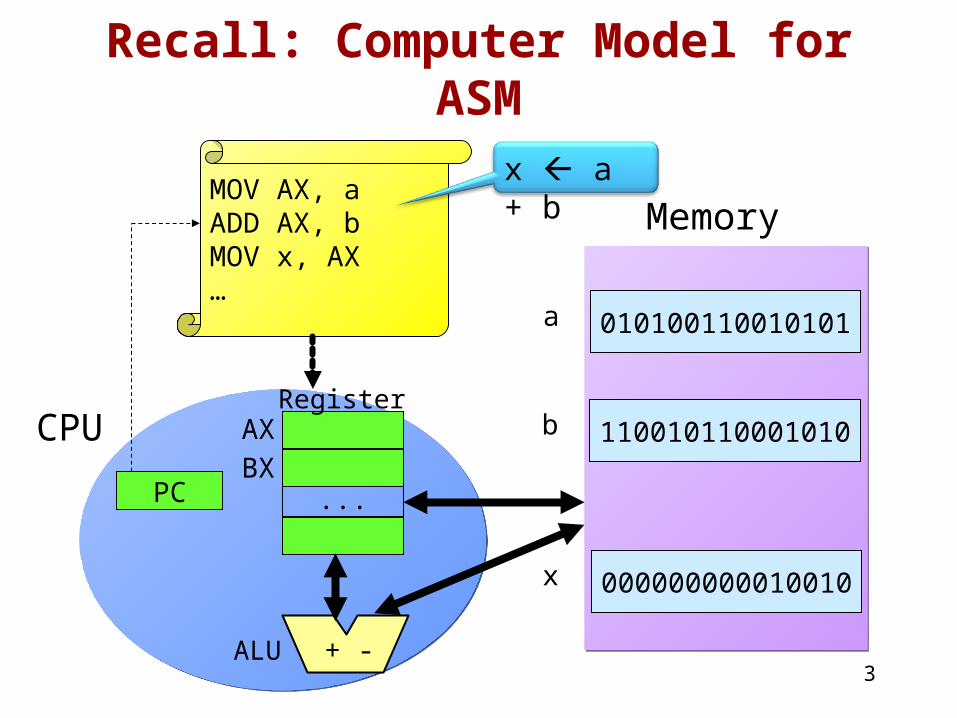
Recall: Computer Model for ASM
CPU
MemoryMOV AX, aADD AX, bMOV x, AX…
010100110010101a
110010110001010b
000000000010010x
AXBX
...
+ -
PC
Register
ALU
x a + b
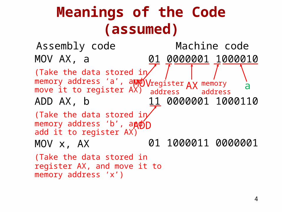
Meanings of the Code (assumed)
Assembly code Machine codeMOV AX, a(Take the data stored inmemory address ‘a’, and move it to register AX)
ADD AX, b(Take the data stored inmemory address ‘b’, and add it to register AX)
MOV x, AX(Take the data stored inregister AX, and move it tomemory address ‘x’)
4
01 0000001 1000010
MOV registeraddress
AX memoryaddress
a
01 1000011 0000001
11 0000001 1000110
ADD
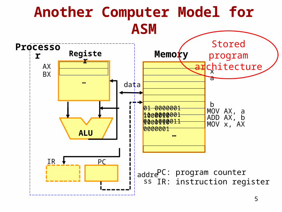
Another Computer Model for ASM
5
…
ALU
MemoryRegister
AXBX
address
01 0000001 1000010 11 0000001 1000110
…
a
b
x
01 1000011 0000001
MOV AX, aADD AX, bMOV x, AX
data
PCIR
PC: program counterIR: instruction register
Stored program
architecture
Processor
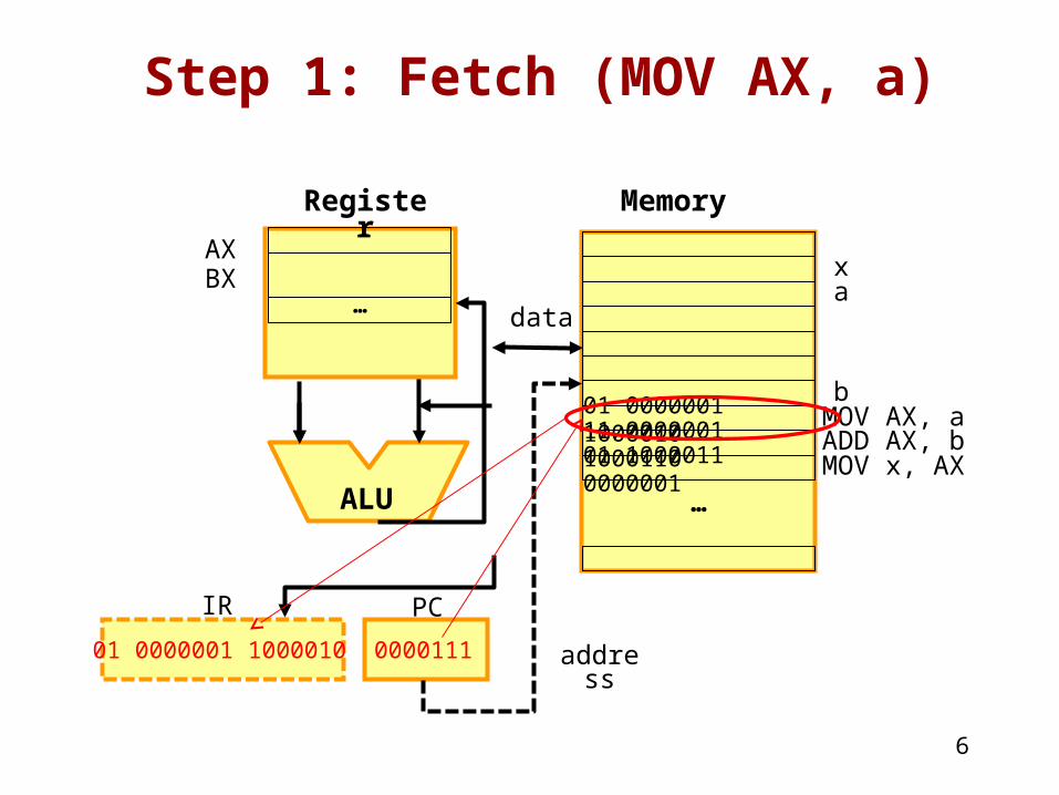
Step 1: Fetch (MOV AX, a)
6
…
ALU
MemoryRegister
AXBX
address
01 0000001 1000010 11 0000001 1000110
…
a
b
x
01 1000011 0000001
MOV AX, aADD AX, bMOV x, AX
data
PC
000011101 0000001 1000010
IR
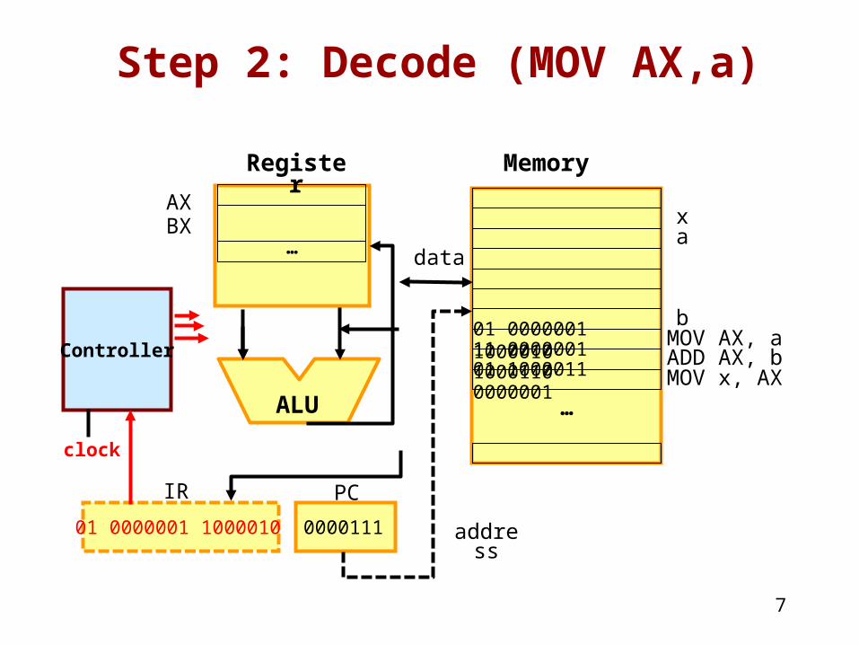
Step 2: Decode (MOV AX,a)
7
…
ALU
MemoryRegister
AXBX
address
01 0000001 1000010 11 0000001 1000110
…
a
b
x
01 1000011 0000001
MOV AX, aADD AX, bMOV x, AX
data
PCIR
000011101 0000001 1000010
Controller
clock
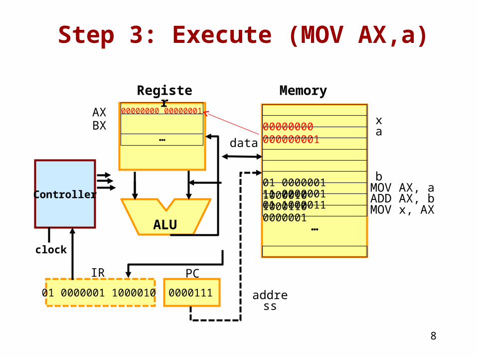
Step 3: Execute (MOV AX,a)
8
…
ALU
MemoryRegister
AXBX
address
00000000 000000001
01 0000001 1000010 11 0000001 1000110
…
a
b
x
01 1000011 0000001
MOV AX, aADD AX, bMOV x, AX
data
PCIR
000011101 0000001 1000010
Controller
clock
00000000 00000001
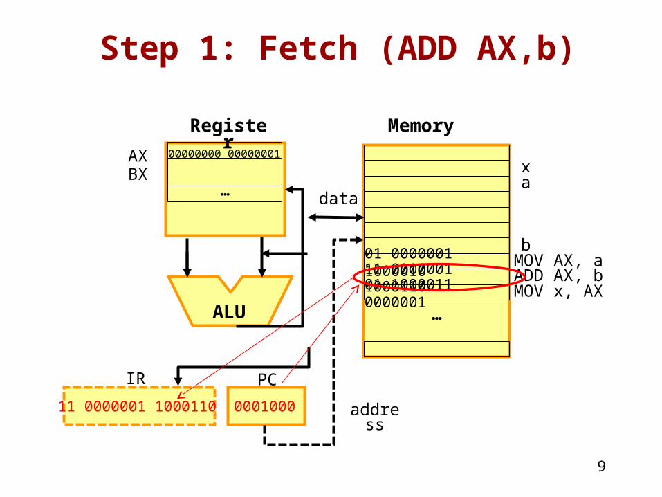
Step 1: Fetch (ADD AX,b)
9
…
ALU
MemoryRegister
AXBX
address
01 0000001 1000010 11 0000001 1000110
…
a
b
x
01 1000011 0000001
MOV AX, aADD AX, bMOV x, AX
data
PC
000100011 0000001 1000110
IR
00000000 00000001
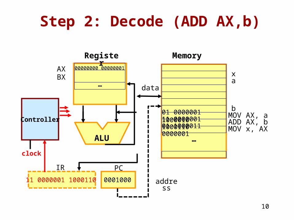
Step 2: Decode (ADD AX,b)
10
…
ALU
MemoryRegister
AXBX
address
01 0000001 1000010 11 0000001 1000110
…
a
b
x
01 1000011 0000001
MOV AX, aADD AX, bMOV x, AX
data
PCIR
000100011 0000001 1000110
Controller
clock
00000000 00000001
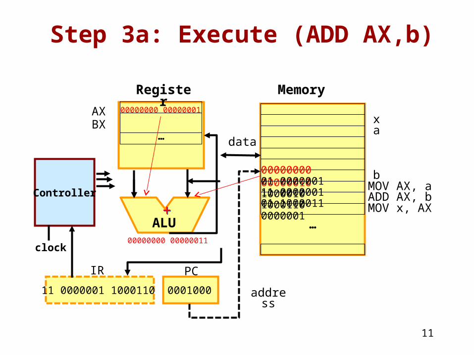
Step 3a: Execute (ADD AX,b)
11
…
ALU
MemoryRegister
AXBX
address
00000000 0000001001 0000001 1000010 11 0000001 1000110
…
a
b
x
01 1000011 0000001
MOV AX, aADD AX, bMOV x, AX
data
PCIR
000100011 0000001 1000110
Controller
clock
00000000 00000001
00000000 00000011
++
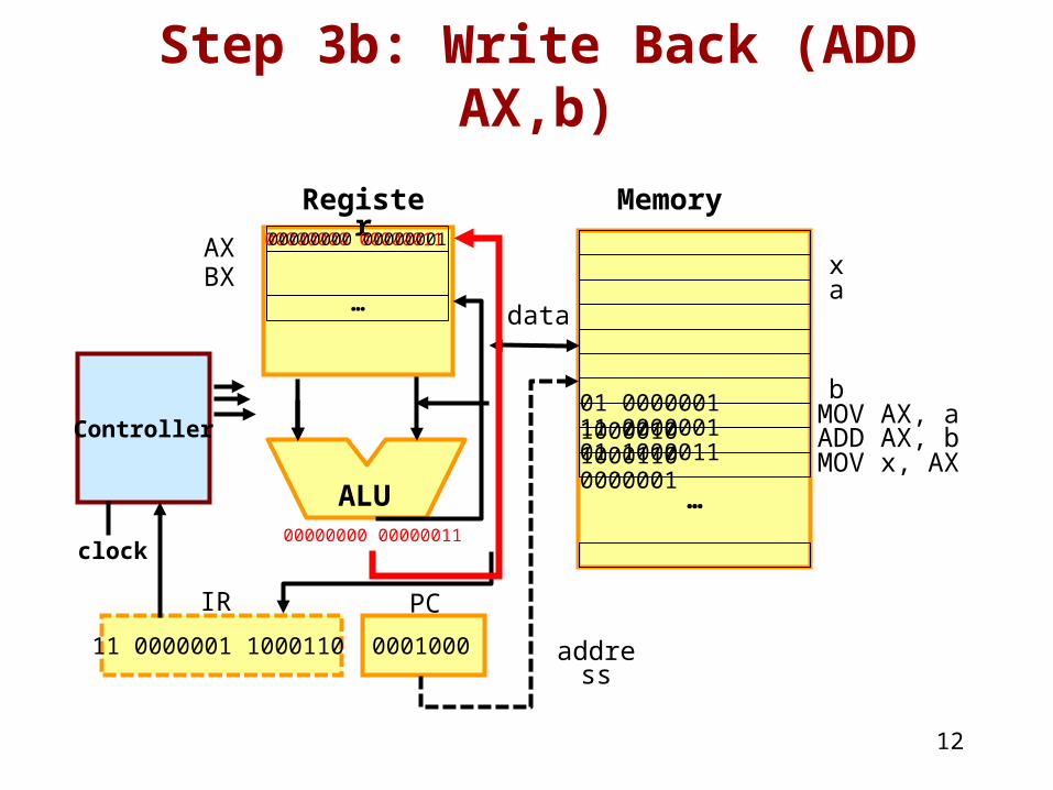
Step 3b: Write Back (ADD AX,b)
12
…
ALU
MemoryRegister
AXBX
address
01 0000001 1000010 11 0000001 1000110
…
a
b
x
01 1000011 0000001
MOV AX, aADD AX, bMOV x, AX
data
PCIR
000100011 0000001 1000110
Controller
clock
00000000 00000011
00000000 00000011
00000000 00000001
13
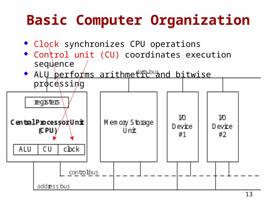
Basic Computer Organization
Clock synchronizes CPU operations Control unit (CU) coordinates execution sequence ALU performs arithmetic and bitwise processing
14
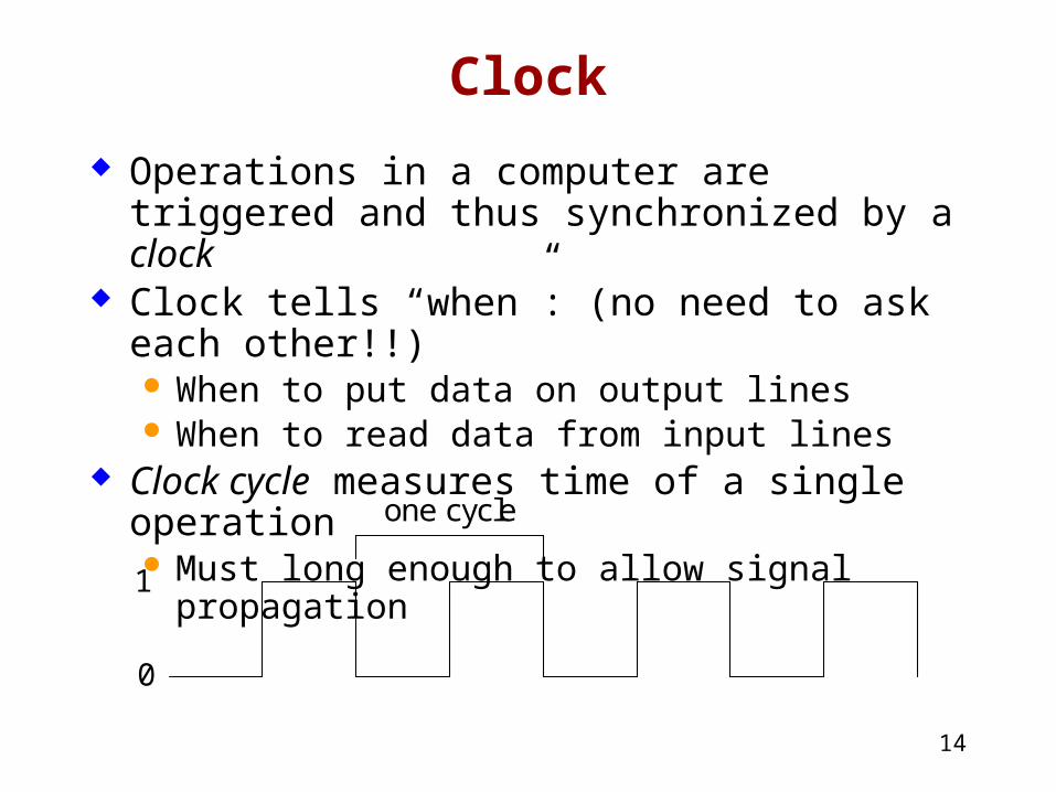
Clock
Operations in a computer are triggered and thus synchronized by a clock
Clock tells “when”: (no need to ask each other!!) When to put data on output lines When to read data from input lines
Clock cycle measures time of a single operation Must long enough to allow signal propagation
one cycle
1
0
15
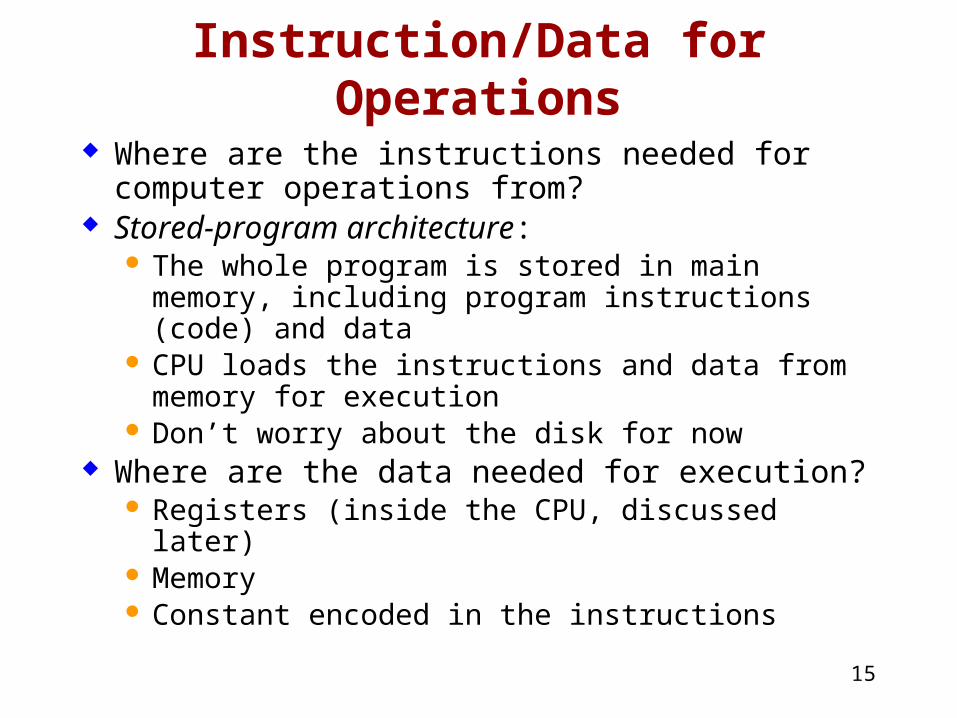
Instruction/Data for Operations
Where are the instructions needed for computer operations from?
Stored-program architecture: The whole program is stored in main memory,
including program instructions (code) and data CPU loads the instructions and data from memory
for execution Don’t worry about the disk for now
Where are the data needed for execution? Registers (inside the CPU, discussed later) Memory Constant encoded in the instructions
16
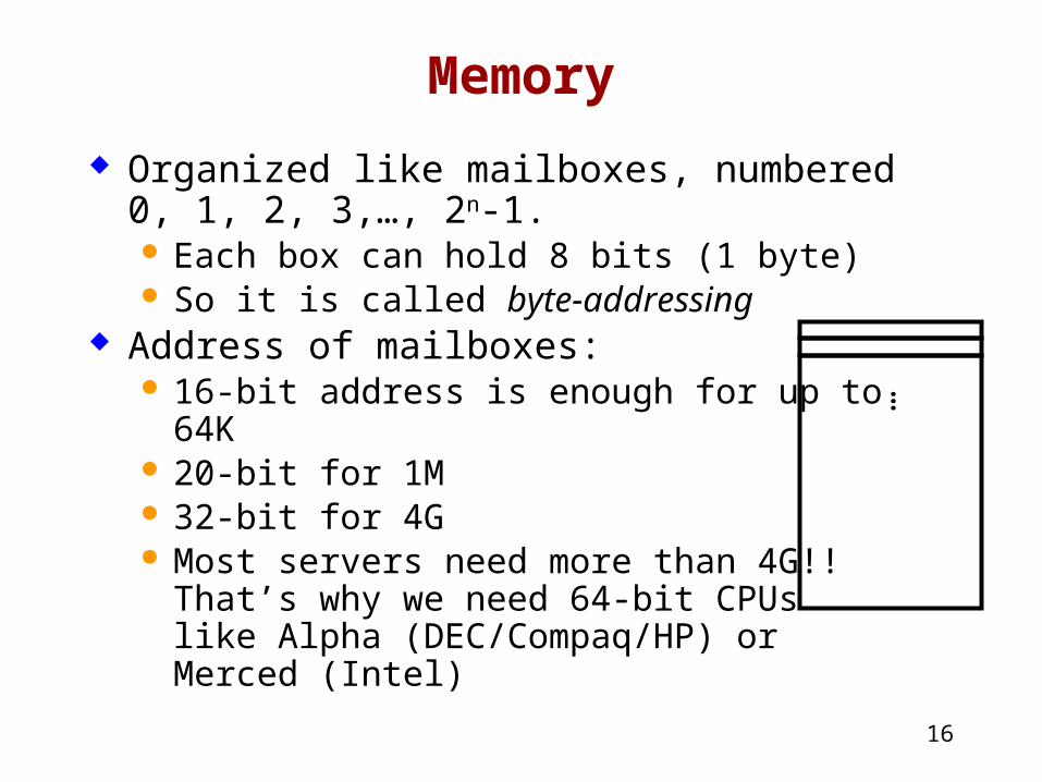
Memory
Organized like mailboxes, numbered 0, 1, 2, 3,…, 2n-1. Each box can hold 8 bits (1 byte) So it is called byte-addressing
Address of mailboxes: 16-bit address is enough for up to 64K 20-bit for 1M 32-bit for 4G Most servers need more than 4G!!
That’s why we need 64-bit CPUs like Alpha (DEC/Compaq/HP) or Merced (Intel)
…
17
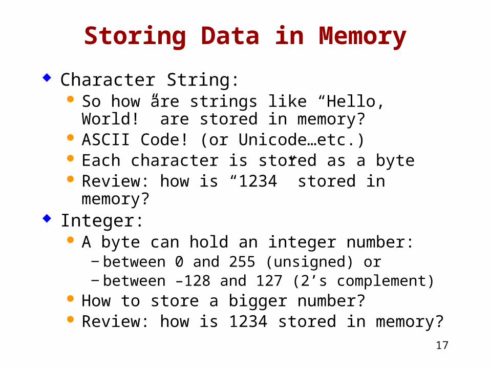
Storing Data in Memory
Character String: So how are strings like “Hello, World!” are stored
in memory? ASCII Code! (or Unicode…etc.) Each character is stored as a byte Review: how is “1234” stored in memory?
Integer: A byte can hold an integer number:
‒ between 0 and 255 (unsigned) or ‒ between –128 and 127 (2’s complement)
How to store a bigger number? Review: how is 1234 stored in memory?
18
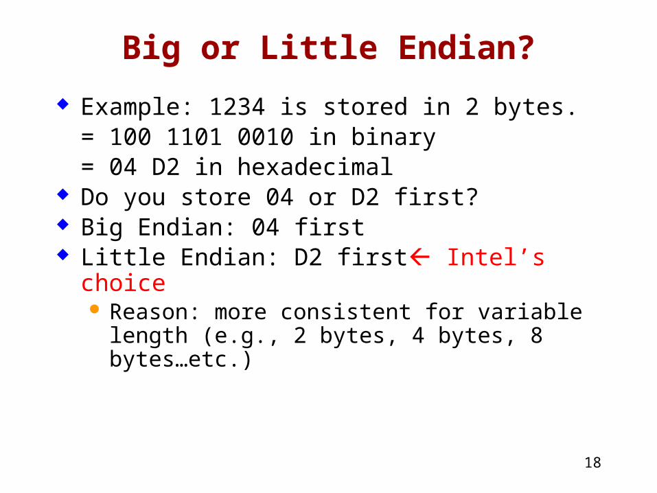
Big or Little Endian?
Example: 1234 is stored in 2 bytes. = 100 1101 0010 in binary= 04 D2 in hexadecimal
Do you store 04 or D2 first? Big Endian: 04 first Little Endian: D2 first Intel’s choice
Reason: more consistent for variable length (e.g., 2 bytes, 4 bytes, 8 bytes…etc.)
19
Cache Memory
High-speed expensive static RAM both inside and outside the CPU. Level-1 cache: inside the CPU chip Level-2 cache: often outside the CPU chip
Cache hit: when data to be read is already in cache memory
Cache miss: when data to be read is not in cache memory
20
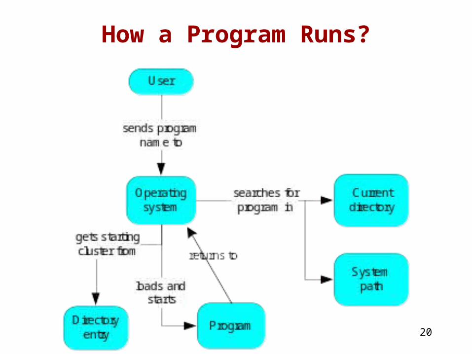
How a Program Runs?
21
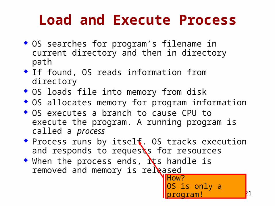
Load and Execute Process
OS searches for program’s filename in current directory and then in directory path
If found, OS reads information from directory OS loads file into memory from disk OS allocates memory for program information OS executes a branch to cause CPU to execute
the program. A running program is called a process
Process runs by itself. OS tracks execution and responds to requests for resources
When the process ends, its handle is removed and memory is released
How?OS is only a program!
22
Multitasking
OS can run multiple programs at same time Multiple threads of execution within the same
program Scheduler utility assigns a given amount of CPU
time to each running program Rapid switching of tasks
Gives illusion that all programs are running at the same time
Processor must support task switching
What supports are needed from hardware?
23
What's Next
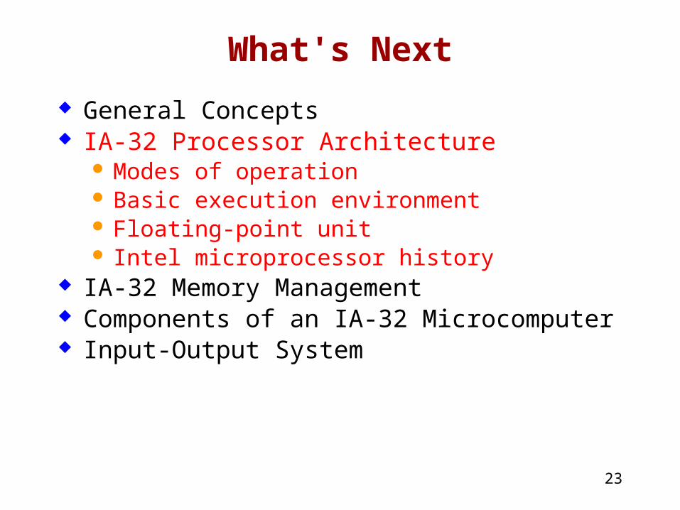
General Concepts IA-32 Processor Architecture
Modes of operation Basic execution environment Floating-point unit Intel microprocessor history
IA-32 Memory Management Components of an IA-32 Microcomputer Input-Output System
24
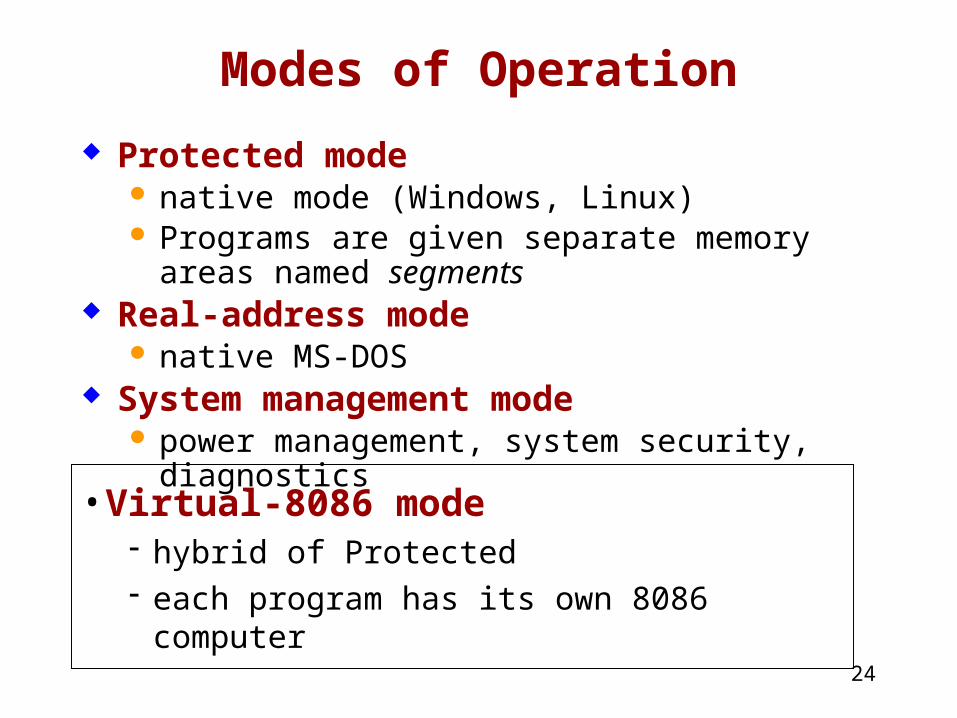
Modes of Operation
Protected mode native mode (Windows, Linux) Programs are given separate memory areas
named segments Real-address mode
native MS-DOS System management mode
power management, system security, diagnostics
• Virtual-8086 mode hybrid of Protected each program has its own 8086 computer
25
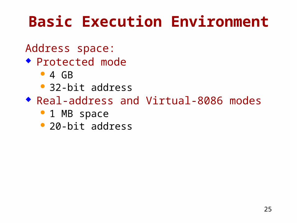
Basic Execution Environment
Address space: Protected mode
4 GB 32-bit address
Real-address and Virtual-8086 modes 1 MB space 20-bit address
26
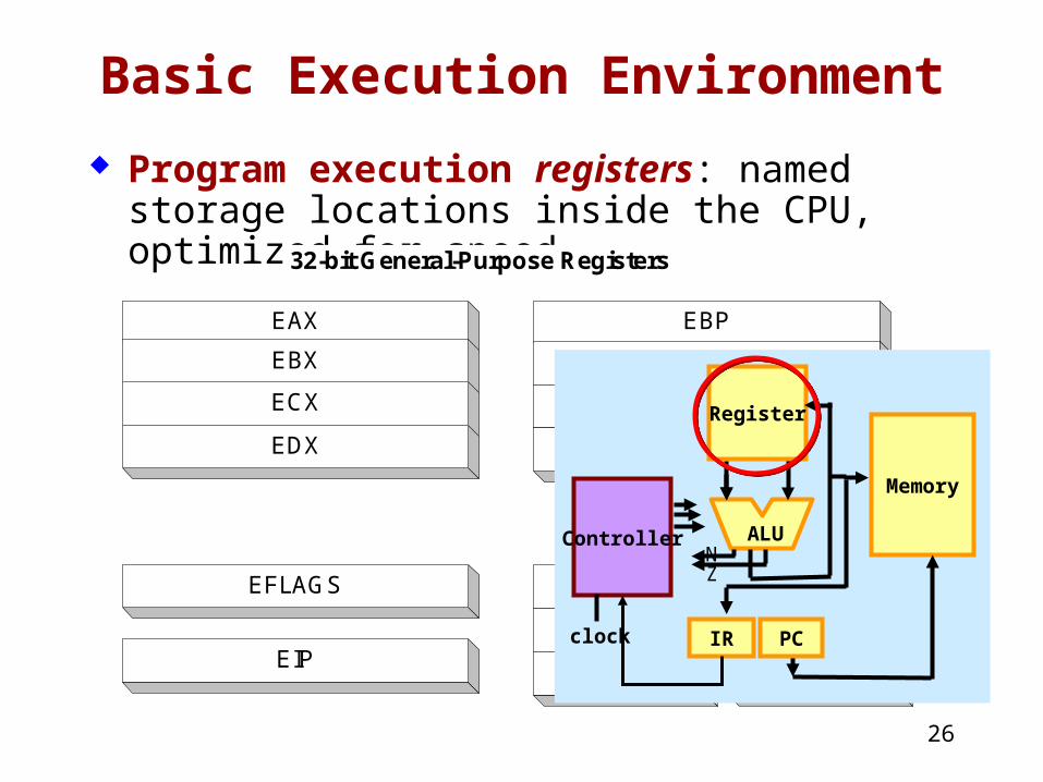
Basic Execution Environment
Program execution registers: named storage locations inside the CPU, optimized for speed
CS
SS
DS
ES
EIP
EFLAGS
16-bit Segment Registers
EAX
EBX
ECX
EDX
32-bit General-Purpose Registers
FS
GS
EBP
ESP
ESI
EDI
ZN
Register
Memory
PCIR
ALU
clock
Controller

27
General Purpose Registers
Used for arithmetic and data movement Addressing:
AX, BX, CX, DX: 16 bits
Split into H and L parts, 8 bits each Extended into E?X to become 32-bit register (i.e.,
EAX, EBX,…etc.)
28
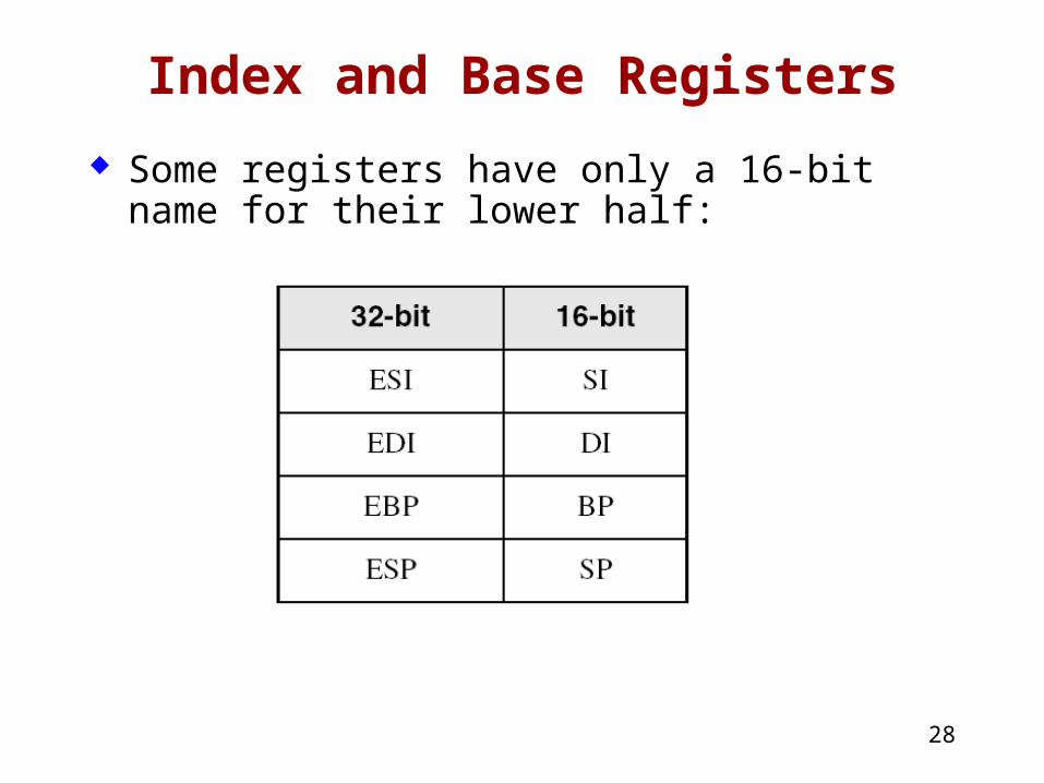
Index and Base Registers
Some registers have only a 16-bit name for their lower half:
29
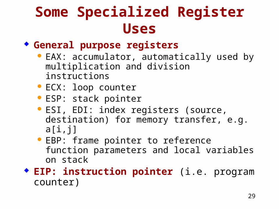
Some Specialized Register Uses
General purpose registers EAX: accumulator, automatically used by
multiplication and division instructions ECX: loop counter ESP: stack pointer ESI, EDI: index registers (source, destination) for
memory transfer, e.g. a[i,j] EBP: frame pointer to reference function
parameters and local variables on stack EIP: instruction pointer (i.e. program counter)
30
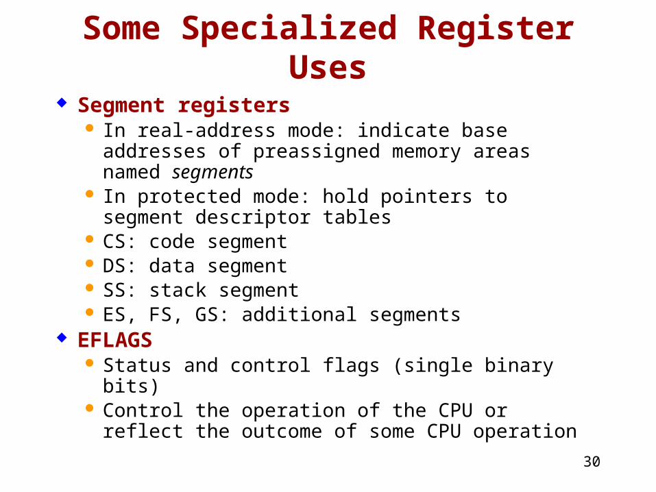
Some Specialized Register Uses
Segment registers In real-address mode: indicate base addresses of
preassigned memory areas named segments In protected mode: hold pointers to segment
descriptor tables CS: code segment DS: data segment SS: stack segment ES, FS, GS: additional segments
EFLAGS Status and control flags (single binary bits) Control the operation of the CPU or reflect the
outcome of some CPU operation
31
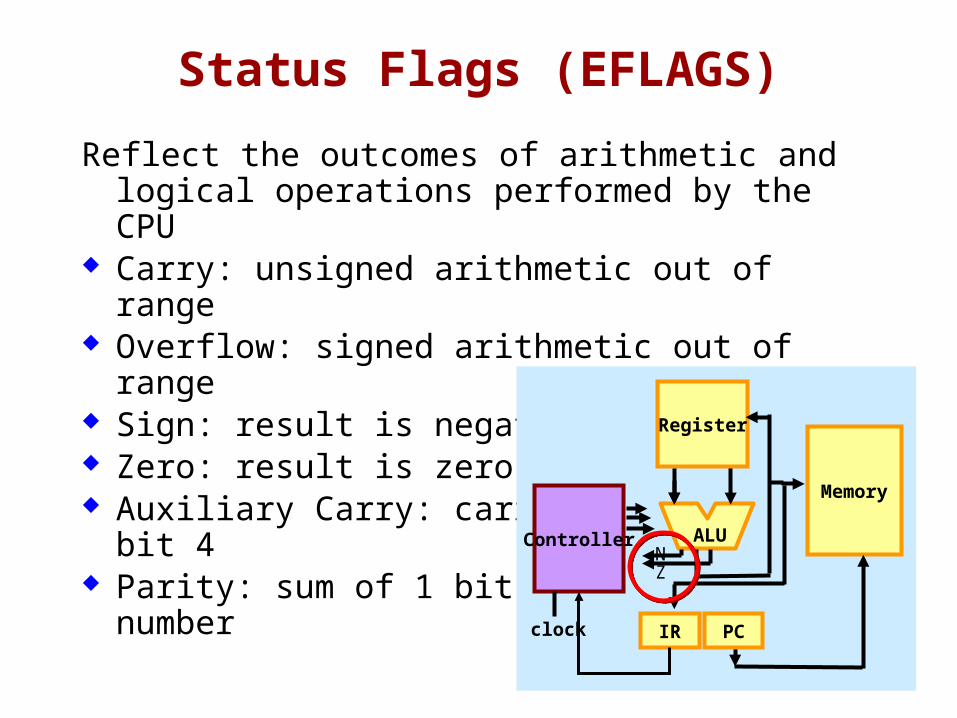
Status Flags (EFLAGS)
Reflect the outcomes of arithmetic and logical operations performed by the CPU
Carry: unsigned arithmetic out of range Overflow: signed arithmetic out of range Sign: result is negative Zero: result is zero Auxiliary Carry: carry from bit 3 to bit 4 Parity: sum of 1 bits is an even number
ZN
Register
Memory
PCIR
ALU
clock
Controller
32
System Registers
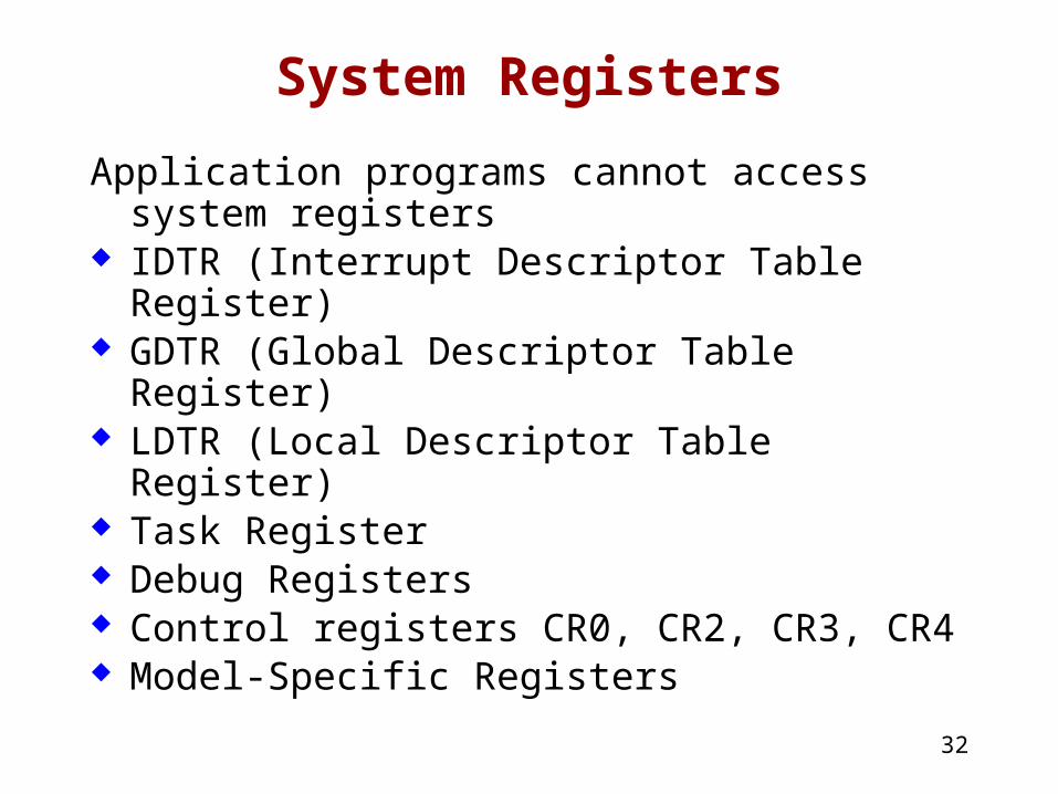
Application programs cannot access system registers
IDTR (Interrupt Descriptor Table Register) GDTR (Global Descriptor Table Register) LDTR (Local Descriptor Table Register) Task Register Debug Registers Control registers CR0, CR2, CR3, CR4 Model-Specific Registers
33
Floating-Point, MMX, XMM Reg.
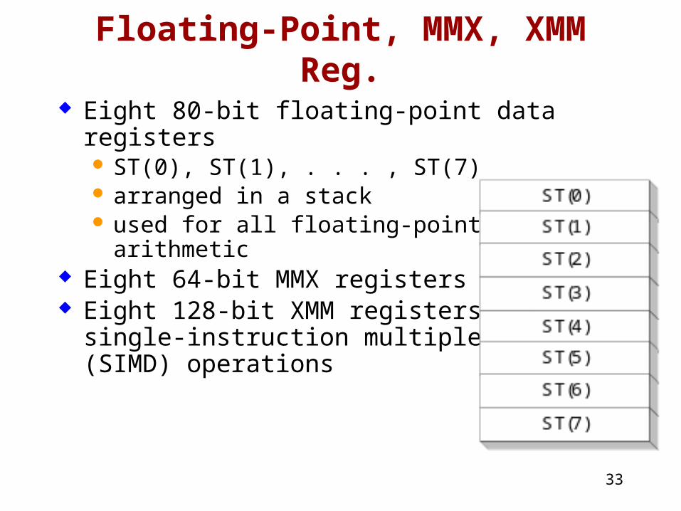
Eight 80-bit floating-point data registers ST(0), ST(1), . . . , ST(7) arranged in a stack used for all floating-point arithmetic
Eight 64-bit MMX registers Eight 128-bit XMM registers for
single-instruction multiple-data(SIMD) operations
34
Intel Microprocessors
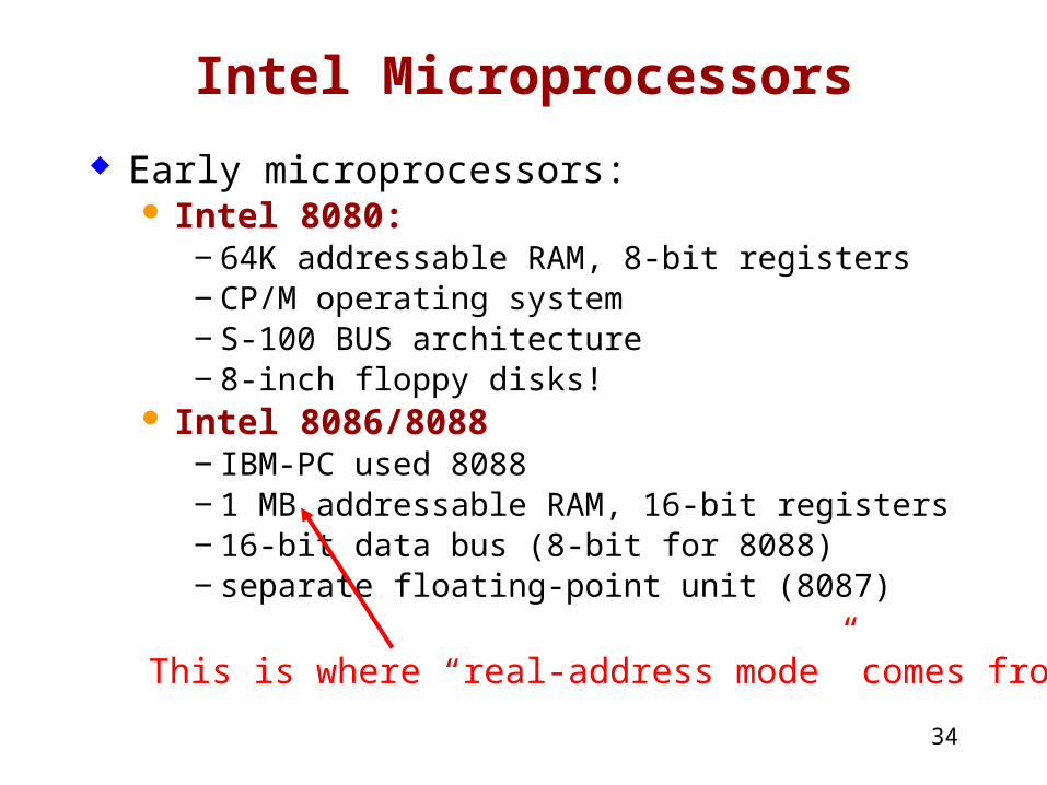
Early microprocessors: Intel 8080:
‒ 64K addressable RAM, 8-bit registers‒ CP/M operating system‒ S-100 BUS architecture‒ 8-inch floppy disks!
Intel 8086/8088‒ IBM-PC used 8088‒ 1 MB addressable RAM, 16-bit registers‒ 16-bit data bus (8-bit for 8088)‒ separate floating-point unit (8087)
This is where “real-address mode” comes from!
35
Intel Microprocessors
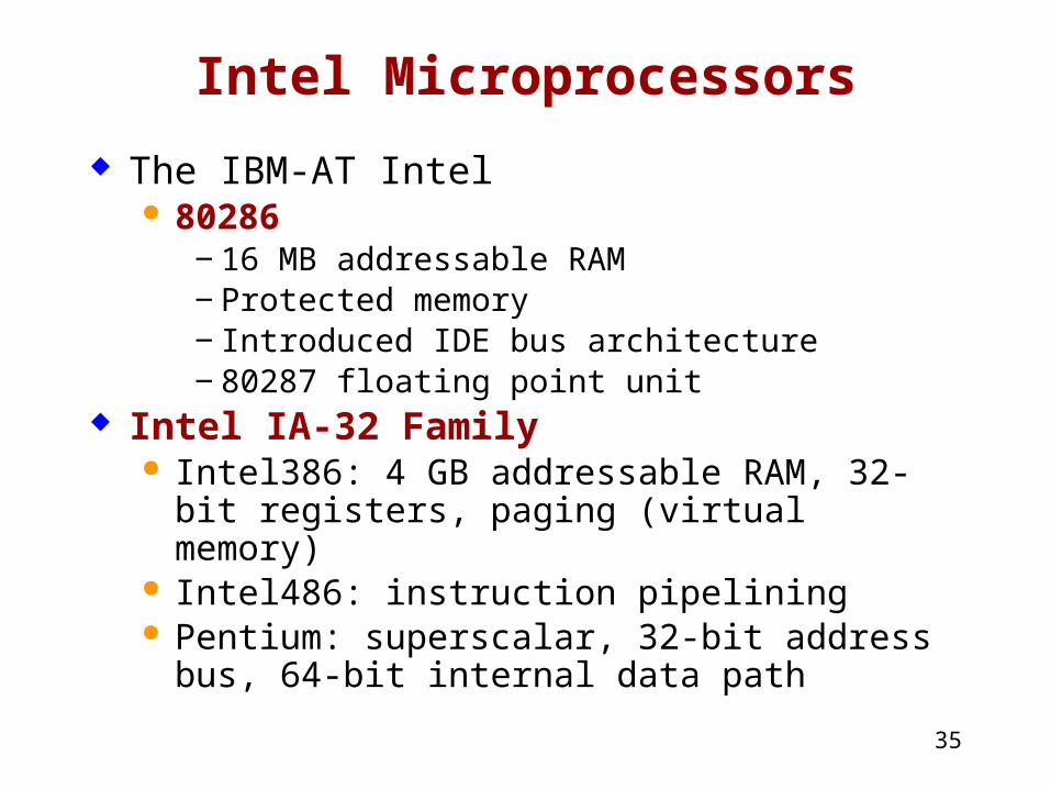
The IBM-AT Intel 80286
‒ 16 MB addressable RAM‒ Protected memory‒ Introduced IDE bus architecture‒ 80287 floating point unit
Intel IA-32 Family Intel386: 4 GB addressable RAM, 32-bit registers,
paging (virtual memory) Intel486: instruction pipelining Pentium: superscalar, 32-bit address bus, 64-bit
internal data path
36
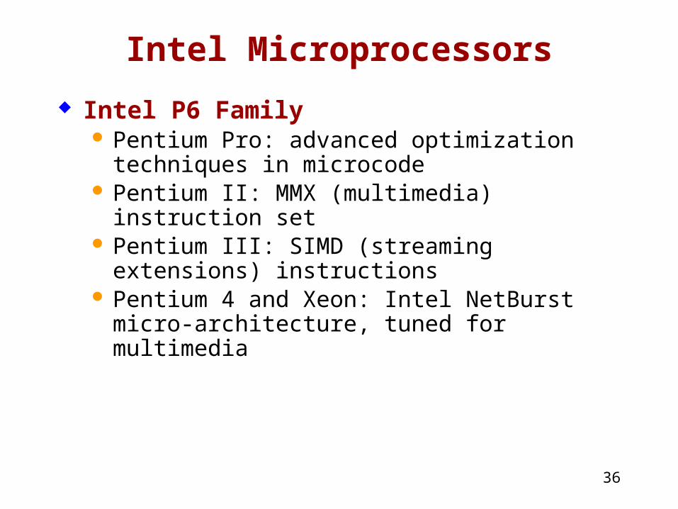
Intel Microprocessors
Intel P6 Family Pentium Pro: advanced optimization techniques in
microcode Pentium II: MMX (multimedia) instruction set Pentium III: SIMD (streaming extensions)
instructions Pentium 4 and Xeon: Intel NetBurst micro-
architecture, tuned for multimedia
37
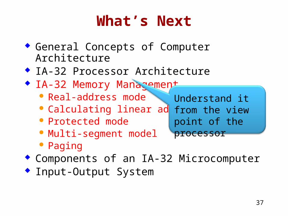
What’s Next
General Concepts of Computer Architecture IA-32 Processor Architecture IA-32 Memory Management
Real-address mode Calculating linear addresses Protected mode Multi-segment model Paging
Components of an IA-32 Microcomputer Input-Output System
Understand it from the view point of the processor
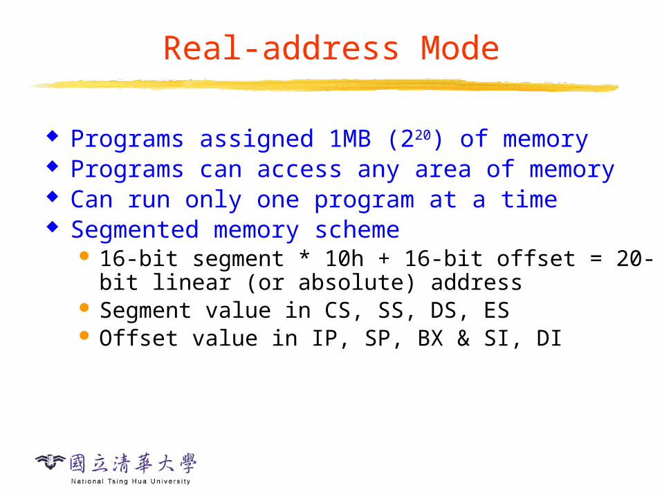
Real-address Mode
Programs assigned 1MB (220) of memory Programs can access any area of memory Can run only one program at a time Segmented memory scheme
16-bit segment * 10h + 16-bit offset = 20-bit linear (or absolute) address
Segment value in CS, SS, DS, ES Offset value in IP, SP, BX & SI, DI
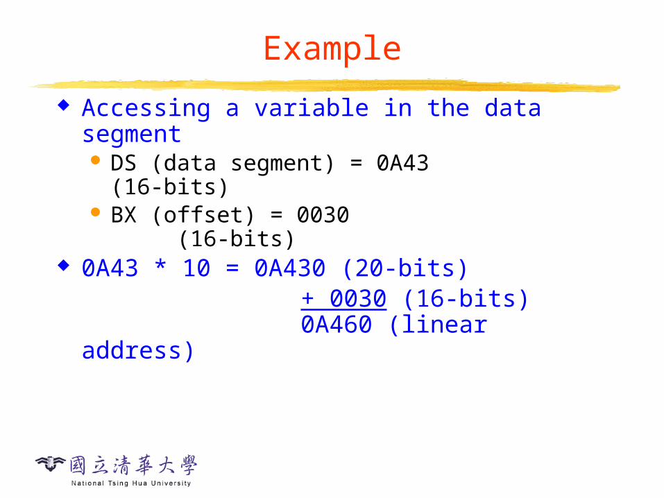
Example
Accessing a variable in the data segment DS (data segment) = 0A43 (16-bits) BX (offset) = 0030 (16-bits)
0A43 * 10 = 0A430 (20-bits) + 0030 (16-bits) 0A460 (linear address)
40
Segmented Memory
l inea
r ad
dres
s es
one segment
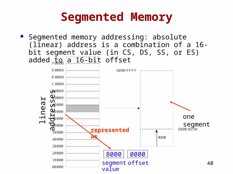
Segmented memory addressing: absolute (linear) address is a combination of a 16-bit segment value (in CS, DS, SS, or ES) added to a 16-bit offset
8000 0000segmentvalue
offset
representedas
41
Calculating Linear Addresses
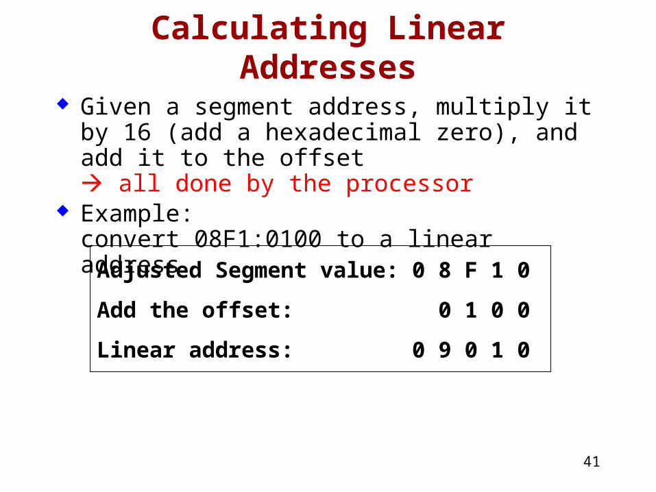
Given a segment address, multiply it by 16 (add a hexadecimal zero), and add it to the offset all done by the processor
Example:convert 08F1:0100 to a linear address
Adjusted Segment value: 0 8 F 1 0
Add the offset: 0 1 0 0
Linear address: 0 9 0 1 0
42
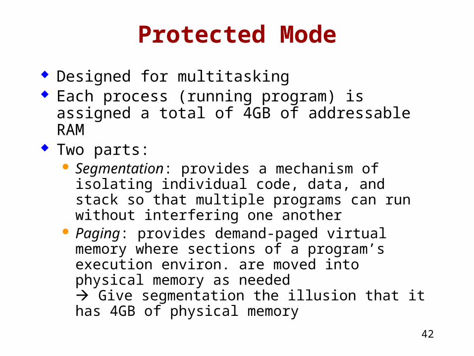
Protected Mode
Designed for multitasking Each process (running program) is assigned a
total of 4GB of addressable RAM Two parts:
Segmentation: provides a mechanism of isolating individual code, data, and stack so that multiple programs can run without interfering one another
Paging: provides demand-paged virtual memory where sections of a program’s execution environ. are moved into physical memory as needed Give segmentation the illusion that it has 4GB of physical memory
43
Segmentation in Protected Mode
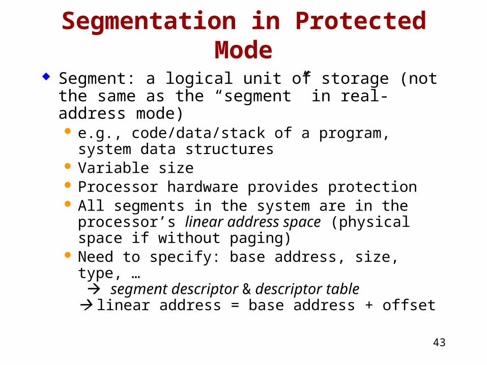
Segment: a logical unit of storage (not the same as the “segment” in real-address mode) e.g., code/data/stack of a program, system data
structures Variable size Processor hardware provides protection All segments in the system are in the processor’s
linear address space (physical space if without paging)
Need to specify: base address, size, type, … segment descriptor & descriptor table linear address = base address + offset
44
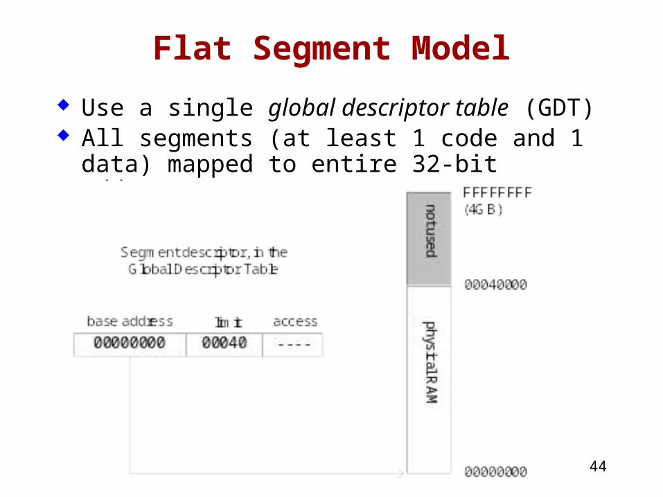
Flat Segment Model
Use a single global descriptor table (GDT) All segments (at least 1 code and 1 data)
mapped to entire 32-bit address space
45
Multi-Segment Model
Local descriptor table (LDT) for each program One descriptor for each segment
located in a system segment of LDT type
46
Segmentation Addressing
Program references a memory location with a logical address: segment selector + offset Segment selector: provides an offset into the
descriptor table CS/DS/SS points to descriptor table for
code/data/stack segment
47
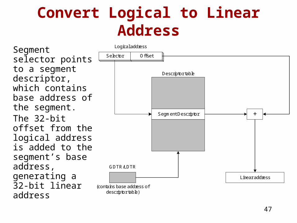
Convert Logical to Linear Address
Segment selector points to a segment descriptor, which contains base address of the segment.The 32-bit offset from the logical address is added to the segment’s base address, generating a 32-bit linear address
Selector Offset
Logical address
Segment Descriptor
Descriptor table
+
GDTR/LDTR
(contains base address ofdescriptor table)
Linear address

48
Paging
Supported directly by the processor Divides each segment into 4096-byte blocks
called pages Part of running program is in memory, part is on
disk Sum of all programs can be larger than physical
memory Virtual memory manager (VMM): An OS utility
that manages loading and unloading of pages Page fault: issued by processor when a page
must be loaded from disk
49
What's Next
General Concepts IA-32 Processor Architecture IA-32 Memory Management Components of an IA-32 Microcomputer
Skipped … Input-Output System
50
What's Next
General Concepts IA-32 Processor Architecture IA-32 Memory Management Components of an IA-32 Microcomputer Input-Output System
How to access I/O systems?
51
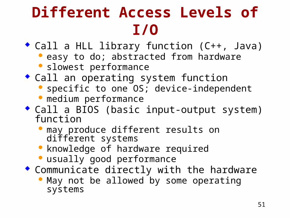
Different Access Levels of I/O Call a HLL library function (C++, Java)
easy to do; abstracted from hardware slowest performance
Call an operating system function specific to one OS; device-independent medium performance
Call a BIOS (basic input-output system) function may produce different results on different systems knowledge of hardware required usually good performance
Communicate directly with the hardware May not be allowed by some operating systems
52
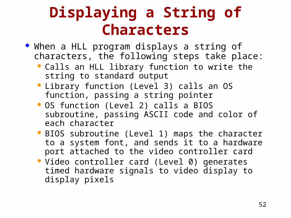
Displaying a String of Characters
When a HLL program displays a string of characters, the following steps take place: Calls an HLL library function to write the string to
standard output Library function (Level 3) calls an OS function,
passing a string pointer OS function (Level 2) calls a BIOS subroutine,
passing ASCII code and color of each character BIOS subroutine (Level 1) maps the character to a
system font, and sends it to a hardware port attached to the video controller card
Video controller card (Level 0) generates timed hardware signals to video display to display pixels
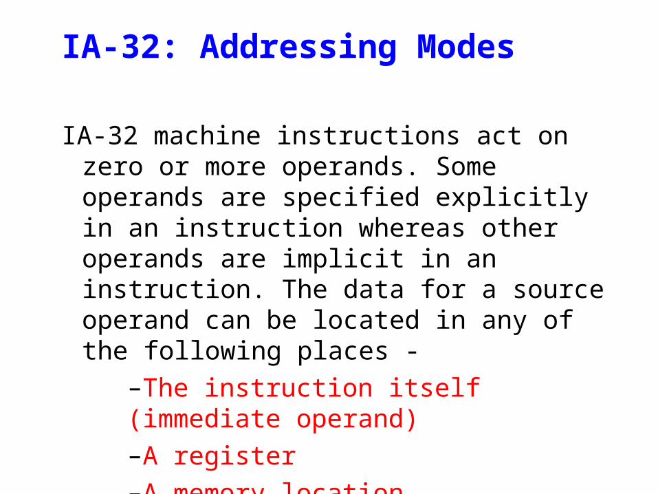
IA-32: Addressing Modes
IA-32 machine instructions act on zero or more operands. Some operands are specified explicitly in an instruction whereas other operands are implicit in an instruction. The data for a source operand can be located in any of the following places -
–The instruction itself (immediate operand) –A register –A memory location –An I/O Port
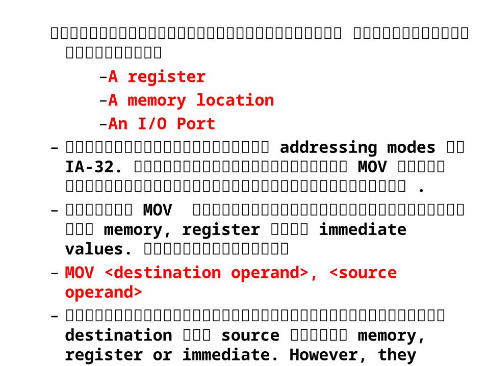
ตั�วแสดงการทำ�างานของรหั�สคำ�าส��ง ข�อมู�ลสามูารถเก�บไว�ทำ��–A register –A memory location –An I/O Port
– เราจะด�คำวามูแตักตั างของ addressing modes ใน IA-32. จะด�จากตั�วอย่ างคำ�าส��ง MOV ทำ��จะอธิ$บาย่การอ�งอ$งแอดเดรสในร�ปแบบตั างๆ .
– คำ�าส��ง MOV ใช้�เคำล(�อนย่�าย่ข�อมู�ลไปหัร(อมูาจาก memory, register หัร(อ immediate values. มู�กฏเกณฑ์,ด�งน�-
– MOV <destination operand>, <source operand>
– ตั�วแสดงการทำ�างานของรหั�สคำ�าส��งในส วนของ destination และ source อย่� ใน memory, register or immediate. However, they can’t both be memory at the same time.
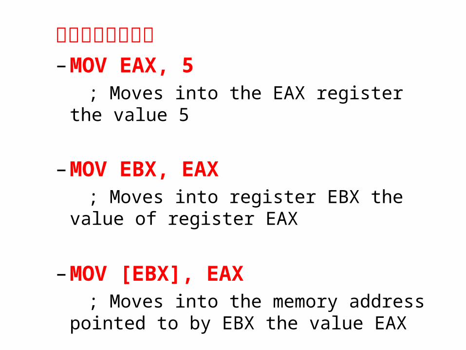
ตั�วอย่ าง – MOV EAX, 5 ; Moves into the EAX register the value
5
– MOV EBX, EAX
; Moves into register EBX the value of register EAX
– MOV [EBX], EAX ; Moves into the memory address
pointed to by EBX the value EAX
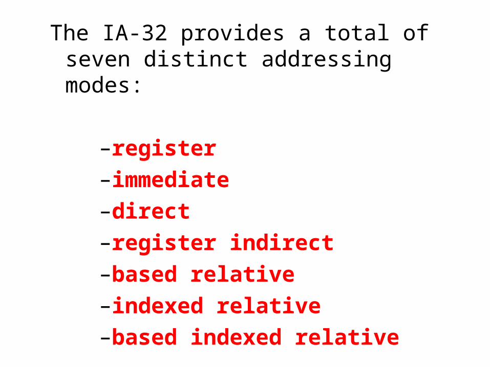
The IA-32 provides a total of seven distinct addressing modes:
–register –immediate –direct –register indirect –based relative –indexed relative –based indexed relative
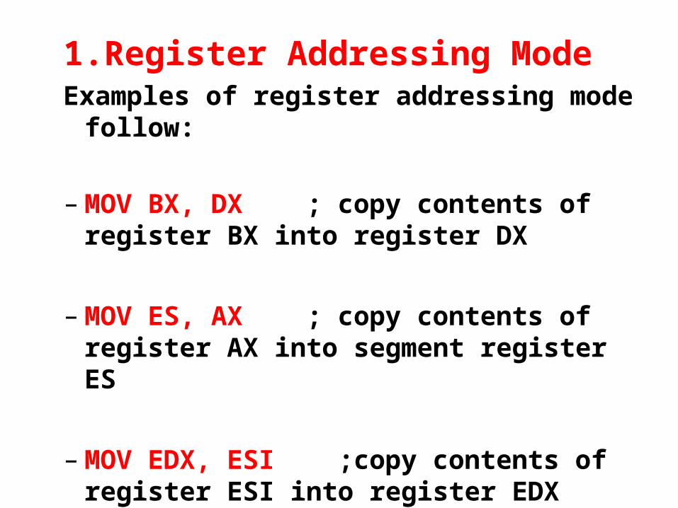
1.Register Addressing ModeExamples of register addressing mode follow:
– MOV BX, DX ; copy contents of register BX into register DX
– MOV ES, AX ; copy contents of register AX into segment register ES
– MOV EDX, ESI ;copy contents of register ESI into register EDX
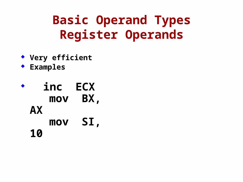
Basic Operand TypesRegister Operands
Very efficient Examples
inc ECX mov BX, AX
mov SI, 10
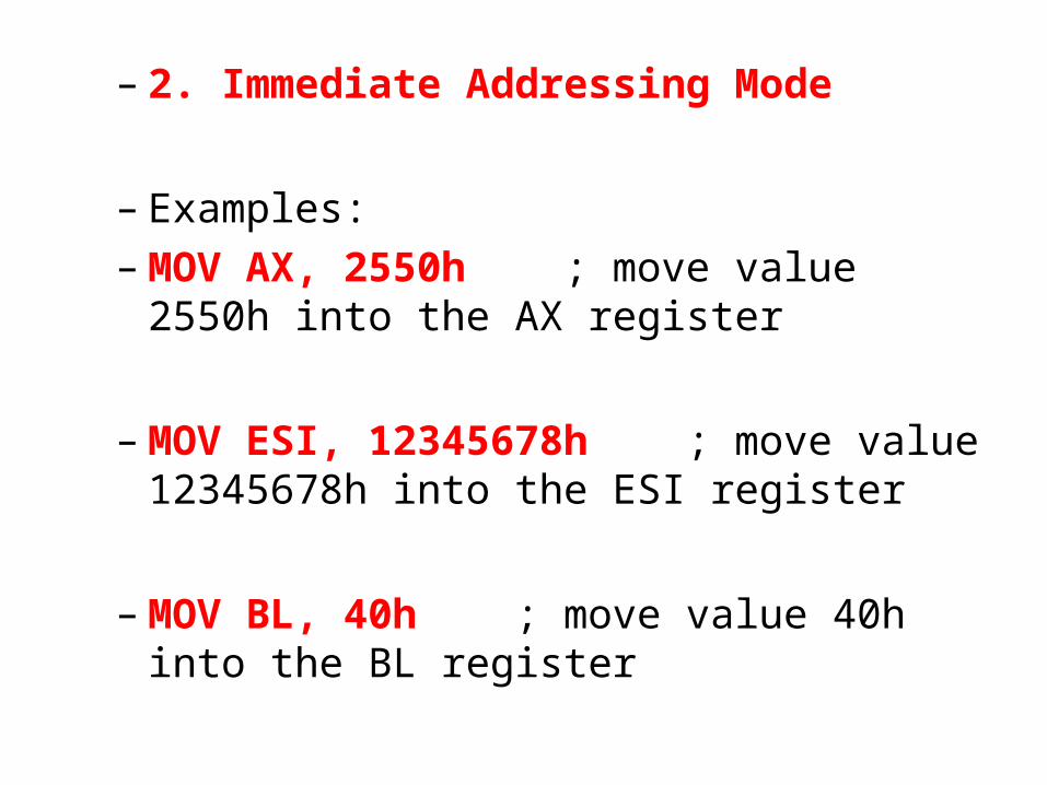
– 2. Immediate Addressing Mode
– Examples:– MOV AX, 2550h ; move value 2550h
into the AX register
– MOV ESI, 12345678h ; move value 12345678h into the ESI register
– MOV BL, 40h ; move value 40h into the BL register
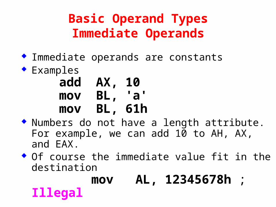
Basic Operand TypesImmediate Operands
Immediate operands are constants Examples
add AX, 10mov BL, 'a'mov BL, 61h
Numbers do not have a length attribute. For example, we can add 10 to AH, AX, and EAX.
Of course the immediate value fit in the destination mov AL, 12345678h ; Illegal
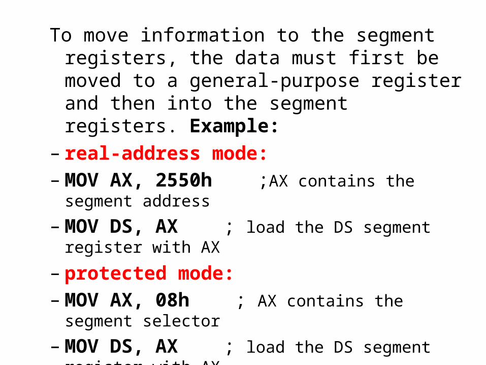
To move information to the segment registers, the data must first be moved to a general-purpose register and then into the segment registers. Example:
– real-address mode:– MOV AX, 2550h ;AX contains the segment address
– MOV DS, AX ; load the DS segment register with AX
– protected mode:– MOV AX, 08h ; AX contains the segment selector
– MOV DS, AX ; load the DS segment register with AX
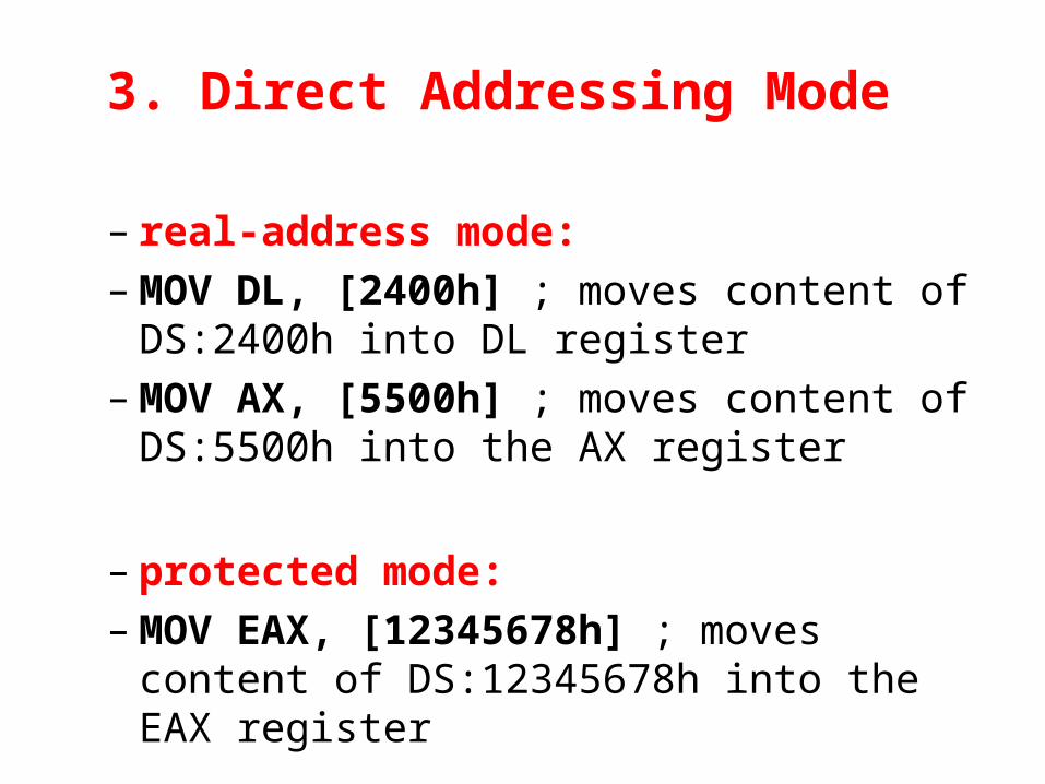
3. Direct Addressing Mode
– real-address mode:– MOV DL, [2400h] ; moves content of DS:2400h
into DL register– MOV AX, [5500h] ; moves content of DS:5500h
into the AX register
– protected mode:– MOV EAX, [12345678h] ; moves content of
DS:12345678h into the EAX register
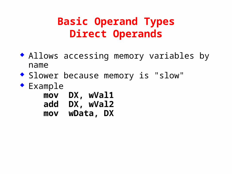
Basic Operand TypesDirect Operands
Allows accessing memory variables by name
Slower because memory is "slow" Example
mov DX, wVal1 add DX, wVal2 mov wData, DX
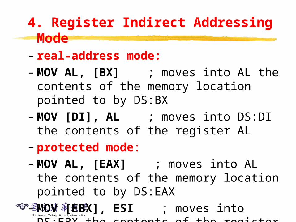
4. Register Indirect Addressing Mode– real-address mode:– MOV AL, [BX] ; moves into AL the contents of
the memory location pointed to by DS:BX– MOV [DI], AL ; moves into DS:DI the contents
of the register AL– protected mode:– MOV AL, [EAX] ; moves into AL the contents of
the memory location pointed to by DS:EAX– MOV [EBX], ESI ; moves into DS:EBX the
contents of the register ESI– MOV BL, [ESI] ; moves into BL the contents of
the memory location pointed to by DS:ESI
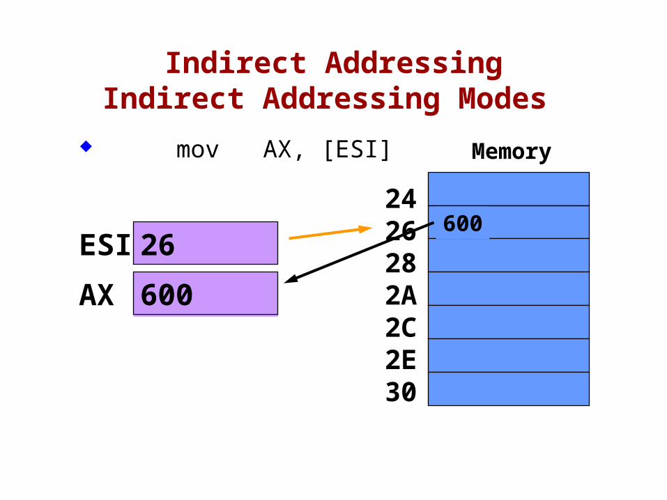
Indirect AddressingIndirect Addressing Modes
mov AX, [ESI]
AX
ESI
Memory
26
2426282A2C2E30
600
600
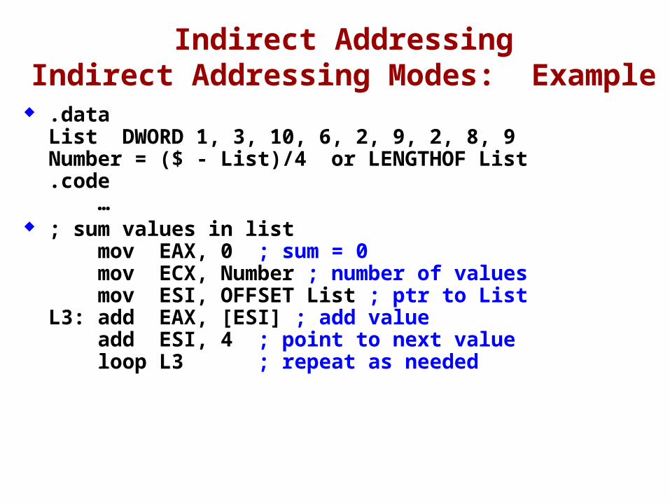
Indirect AddressingIndirect Addressing Modes: Example
.dataList DWORD 1, 3, 10, 6, 2, 9, 2, 8, 9 Number = ($ - List)/4 or LENGTHOF List.code …
; sum values in list mov EAX, 0 ; sum = 0 mov ECX, Number ; number of values mov ESI, OFFSET List ; ptr to ListL3: add EAX, [ESI] ; add value add ESI, 4 ; point to next value loop L3 ; repeat as needed
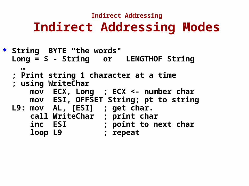
Indirect Addressing
Indirect Addressing Modes
String BYTE "the words"Long = $ - String or LENGTHOF String …; Print string 1 character at a time ; using WriteChar mov ECX, Long ; ECX <- number char mov ESI, OFFSET String; pt to stringL9: mov AL, [ESI] ; get char. call WriteChar ; print char inc ESI ; point to next char loop L9 ; repeat
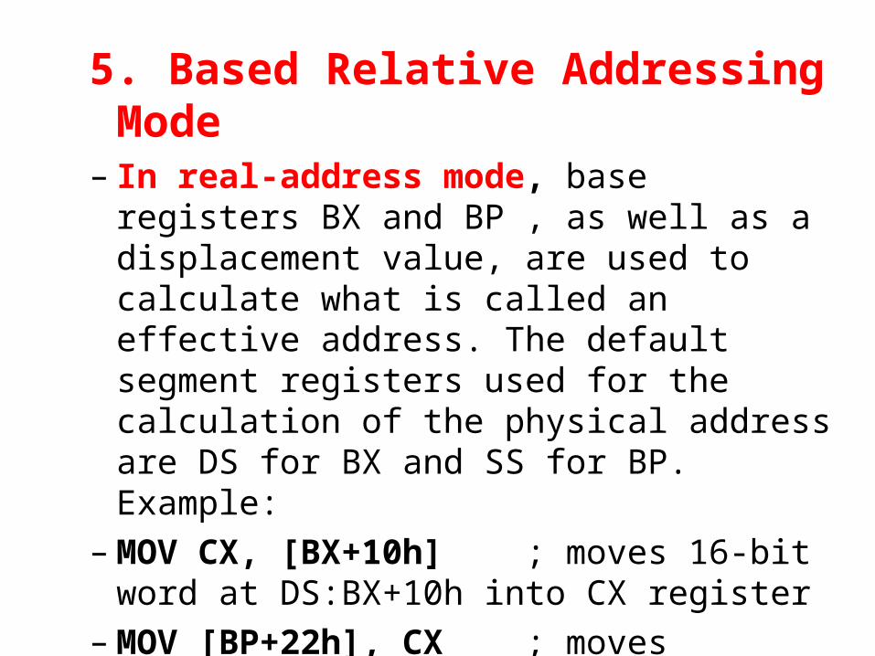
5. Based Relative Addressing Mode– In real-address mode, base registers BX and BP ,
as well as a displacement value, are used to calculate what is called an effective address. The default segment registers used for the calculation of the physical address are DS for BX and SS for BP. Example:
– MOV CX, [BX+10h] ; moves 16-bit word at DS:BX+10h into CX register
– MOV [BP+22h], CX ; moves contents of CX register into memory location SS:BP+22h
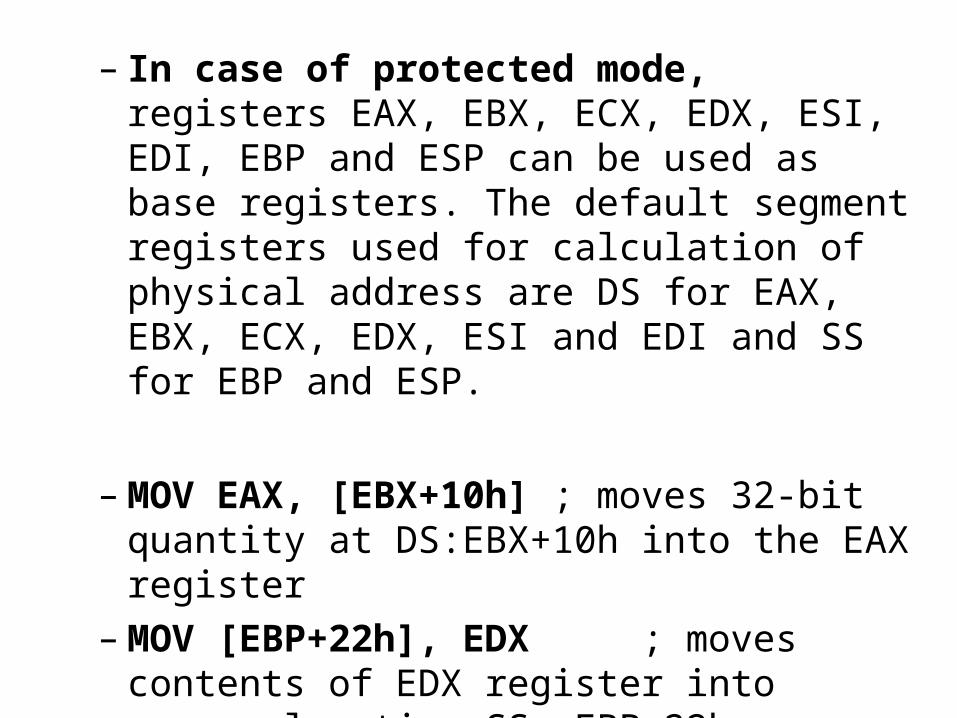
– In case of protected mode, registers EAX, EBX, ECX, EDX, ESI, EDI, EBP and ESP can be used as base registers. The default segment registers used for calculation of physical address are DS for EAX, EBX, ECX, EDX, ESI and EDI and SS for EBP and ESP.
– MOV EAX, [EBX+10h] ; moves 32-bit quantity at DS:EBX+10h into the EAX register
– MOV [EBP+22h], EDX ; moves contents of EDX register into memory location SS: EBP+22h
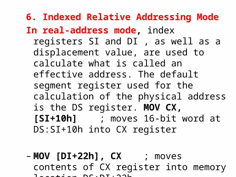
6. Indexed Relative Addressing ModeIn real-address mode, index registers SI
and DI , as well as a displacement value, are used to calculate what is called an effective address. The default segment register used for the calculation of the physical address is the DS register. MOV CX, [SI+10h] ; moves 16-bit word at DS:SI+10h into CX register
– MOV [DI+22h], CX ; moves contents of CX register into memory location DS:DI+22h
– MOV EAX, [ESI+10h] ; moves 32-bit quantity at DS:ESI+10h into the EAX register
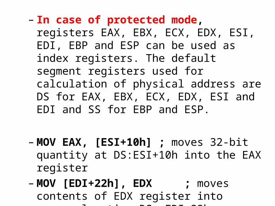
– In case of protected mode, registers EAX, EBX, ECX, EDX, ESI, EDI, EBP and ESP can be used as index registers. The default segment registers used for calculation of physical address are DS for EAX, EBX, ECX, EDX, ESI and EDI and SS for EBP and ESP.
– MOV EAX, [ESI+10h] ; moves 32-bit quantity at DS:ESI+10h into the EAX register
– MOV [EDI+22h], EDX ; moves contents of EDX register into memory location DS: EDI+22h
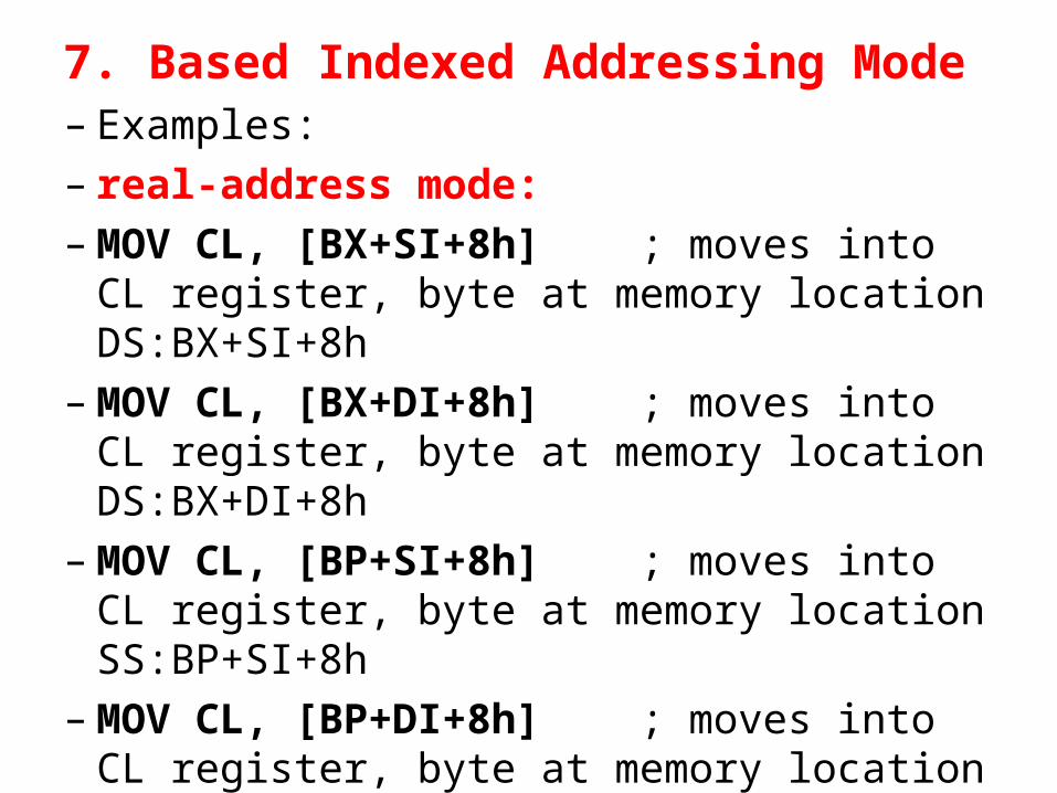
7. Based Indexed Addressing Mode– Examples:– real-address mode:– MOV CL, [BX+SI+8h] ; moves into CL
register, byte at memory location DS:BX+SI+8h
– MOV CL, [BX+DI+8h] ; moves into CL register, byte at memory location DS:BX+DI+8h
– MOV CL, [BP+SI+8h] ; moves into CL register, byte at memory location SS:BP+SI+8h
– MOV CL, [BP+DI+8h] ; moves into CL register, byte at memory location DS:BP+DI+8h
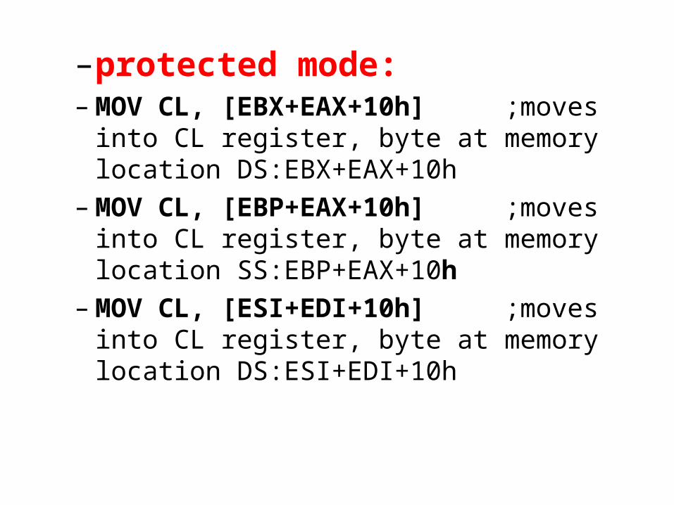
– protected mode:– MOV CL, [EBX+EAX+10h] ;moves into CL
register, byte at memory location DS:EBX+EAX+10h
– MOV CL, [EBP+EAX+10h] ;moves into CL register, byte at memory location SS:EBP+EAX+10h
– MOV CL, [ESI+EDI+10h] ;moves into CL register, byte at memory location DS:ESI+EDI+10h
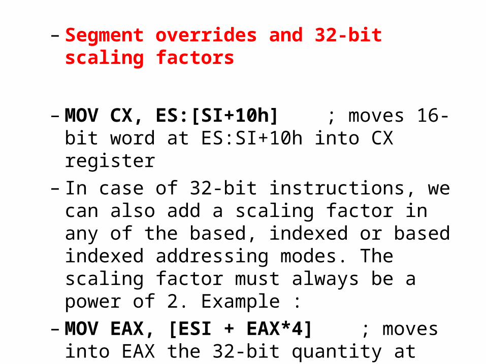
– Segment overrides and 32-bit scaling factors
– MOV CX, ES:[SI+10h] ; moves 16-bit word at ES:SI+10h into CX register
– In case of 32-bit instructions, we can also add a scaling factor in any of the based, indexed or based indexed addressing modes. The scaling factor must always be a power of 2. Example :
– MOV EAX, [ESI + EAX*4] ; moves into EAX the 32-bit quantity at DS:ESI+EAX*4
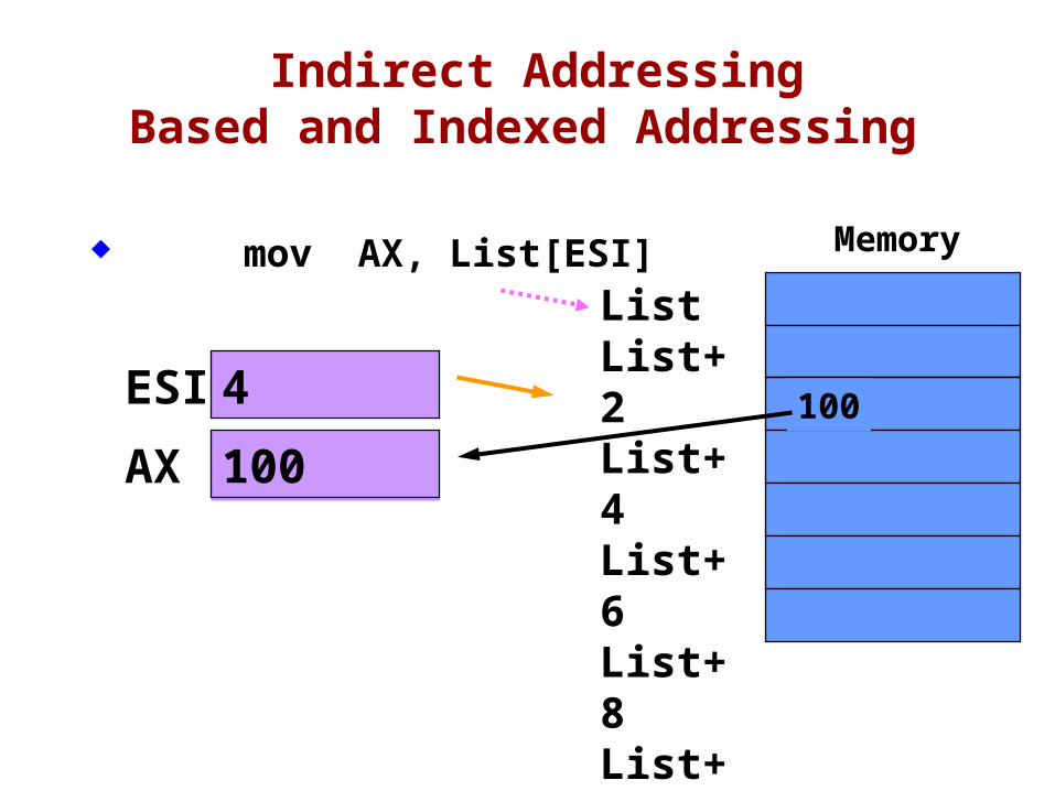
Indirect AddressingBased and Indexed Addressing
mov AX, List[ESI]
AX
ESI 4
ListList+2List+4List+6List+8List+10List+12
Memory
100
100
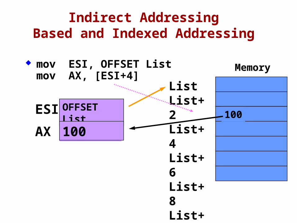
Indirect AddressingBased and Indexed Addressing
mov ESI, OFFSET Listmov AX, [ESI+4]
AX
ESI OFFSET List
ListList+2List+4List+6List+8List+10List+12
Memory
100
100
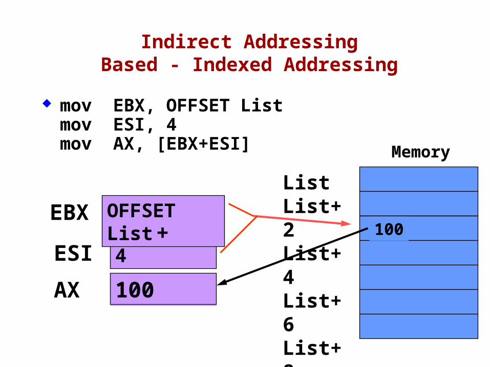
Indirect AddressingBased - Indexed Addressing
mov EBX, OFFSET Listmov ESI, 4mov AX, [EBX+ESI]
AX
ESI 4
ListList+2List+4List+6List+8List+10List+12
Memory
100
100
EBX OFFSET List+
78
Summary
Central Processing Unit (CPU) Arithmetic Logic Unit (ALU) Instruction execution cycle Multitasking Floating Point Unit (FPU) Complex Instruction Set Real mode and Protected mode Motherboard components Memory types Input/Output and access levels