Embed Size (px)
Citation preview
1
1/4/2005 COSC 4213 - S.Datta 1
COSC 4213: Computer Networks II
Suprakash [email protected]
These slides are adapted from Jim Kurose’s slides.
1/4/2005 COSC 4213 - S.Datta 2
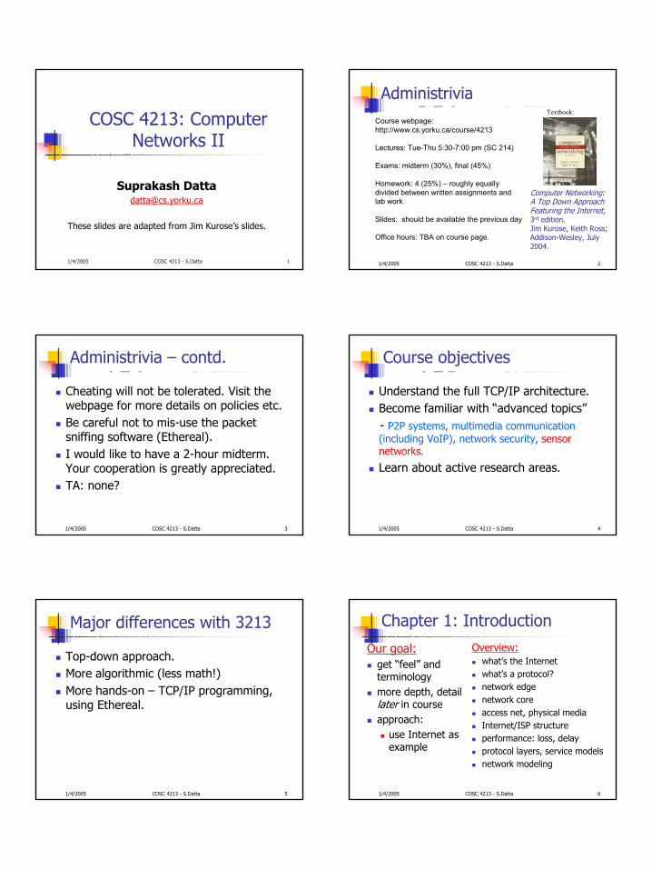
Administrivia
Computer Networking: A Top Down Approach Featuring the Internet, 3rd edition. Jim Kurose, Keith Ross; Addison-Wesley, July 2004.
Course webpage: http://www.cs.yorku.ca/course/4213
Lectures: Tue-Thu 5:30-7:00 pm (SC 214)
Exams: midterm (30%), final (45%)
Homework: 4 (25%) – roughly equally divided between written assignments and lab work.
Slides: should be available the previous day
Office hours: TBA on course page.
Textbook:
1/4/2005 COSC 4213 - S.Datta 3
Administrivia – contd.
Cheating will not be tolerated. Visit the webpage for more details on policies etc.Be careful not to mis-use the packet sniffing software (Ethereal).I would like to have a 2-hour midterm. Your cooperation is greatly appreciated.TA: none?
1/4/2005 COSC 4213 - S.Datta 4
Course objectives
Understand the full TCP/IP architecture.Become familiar with “advanced topics”- P2P systems, multimedia communication (including VoIP), network security, sensor networks.
Learn about active research areas.
1/4/2005 COSC 4213 - S.Datta 5
Major differences with 3213
Top-down approach.More algorithmic (less math!)More hands-on – TCP/IP programming, using Ethereal.
1/4/2005 COSC 4213 - S.Datta 6
Chapter 1: Introduction
Our goal:get “feel” and terminologymore depth, detail later in courseapproach:
use Internet as example
Overview:what’s the Internetwhat’s a protocol?network edgenetwork coreaccess net, physical mediaInternet/ISP structureperformance: loss, delayprotocol layers, service modelsnetwork modeling
2
1/4/2005 COSC 4213 - S.Datta 7
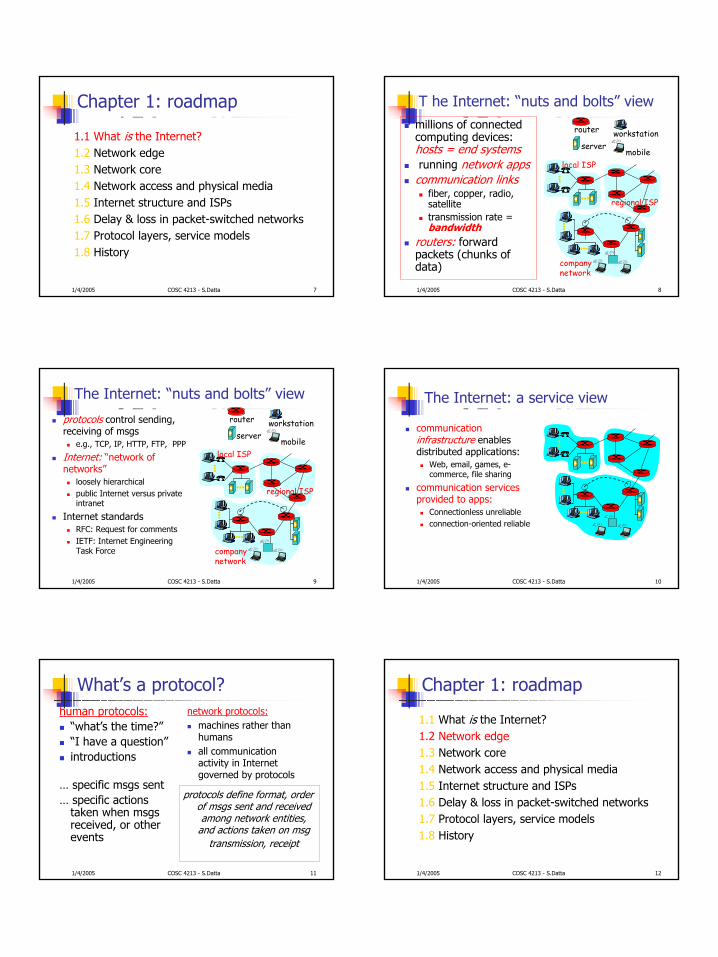
Chapter 1: roadmap
1.1 What is the Internet?1.2 Network edge1.3 Network core1.4 Network access and physical media1.5 Internet structure and ISPs1.6 Delay & loss in packet-switched networks1.7 Protocol layers, service models1.8 History
1/4/2005 COSC 4213 - S.Datta 8
T he Internet: “nuts and bolts” viewmillions of connected computing devices: hosts = end systemsrunning network appscommunication links
fiber, copper, radio, satellitetransmission rate = bandwidth
routers: forward packets (chunks of data)
local ISP
companynetwork
regional ISP
router workstationserver
mobile
1/4/2005 COSC 4213 - S.Datta 9
The Internet: “nuts and bolts” view
protocols control sending, receiving of msgs
e.g., TCP, IP, HTTP, FTP, PPP
Internet: “network of networks”
loosely hierarchicalpublic Internet versus private intranet
Internet standardsRFC: Request for commentsIETF: Internet Engineering Task Force
local ISP
companynetwork
regional ISP
router workstationserver
mobile
1/4/2005 COSC 4213 - S.Datta 10
The Internet: a service view
communication infrastructure enables distributed applications:
Web, email, games, e-commerce, file sharing
communication services provided to apps:
Connectionless unreliableconnection-oriented reliable
1/4/2005 COSC 4213 - S.Datta 11
What’s a protocol?human protocols:
“what’s the time?”“I have a question”introductions
… specific msgs sent… specific actions
taken when msgsreceived, or other events
network protocols:machines rather than humansall communication activity in Internet governed by protocols
protocols define format, order of msgs sent and received among network entities,
and actions taken on msgtransmission, receipt
1/4/2005 COSC 4213 - S.Datta 12
Chapter 1: roadmap
1.1 What is the Internet?1.2 Network edge1.3 Network core1.4 Network access and physical media1.5 Internet structure and ISPs1.6 Delay & loss in packet-switched networks1.7 Protocol layers, service models1.8 History
3
1/4/2005 COSC 4213 - S.Datta 13
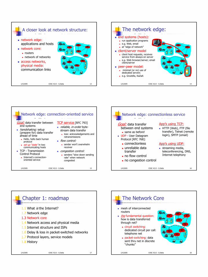
A closer look at network structure:
network edge:applications and hostsnetwork core:
routersnetwork of networks
access networks, physical media:communication links
1/4/2005 COSC 4213 - S.Datta 14
The network edge:end systems (hosts):
run application programse.g. Web, emailat “edge of network”
client/server modelclient host requests, receives service from always-on servere.g. Web browser/server; email client/server
peer-peer model:minimal (or no) use of dedicated serverse.g. Gnutella, KaZaA
1/4/2005 COSC 4213 - S.Datta 15
Network edge: connection-oriented service
Goal: data transfer between end systemshandshaking: setup (prepare for) data transfer ahead of time
Hello, hello back human protocolset up “state” in two communicating hosts
TCP - Transmission Control Protocol
Internet’s connection-oriented service
TCP service [RFC 793]reliable, in-order byte-stream data transfer
loss: acknowledgements and retransmissions
flow control:sender won’t overwhelm receiver
congestion control:senders “slow down sending rate” when network congested
1/4/2005 COSC 4213 - S.Datta 16
Network edge: connectionless service
Goal: data transfer between end systems
same as before!UDP - User DatagramProtocol [RFC 768]:
connectionless unreliable data transferno flow controlno congestion control
App’s using TCP:HTTP (Web), FTP (file transfer), Telnet (remote login), SMTP (email)
App’s using UDP:streaming media, teleconferencing, DNS, Internet telephony
1/4/2005 COSC 4213 - S.Datta 17
Chapter 1: roadmap
1.1 What is the Internet?1.2 Network edge1.3 Network core1.4 Network access and physical media1.5 Internet structure and ISPs1.6 Delay & loss in packet-switched networks1.7 Protocol layers, service models1.8 History
1/4/2005 COSC 4213 - S.Datta 18
The Network Core
mesh of interconnected routersthe fundamental question:how is data transferred through net?
circuit switching:dedicated circuit per call: telephone netpacket-switching: data sent thru net in discrete “chunks”
4
1/4/2005 COSC 4213 - S.Datta 19
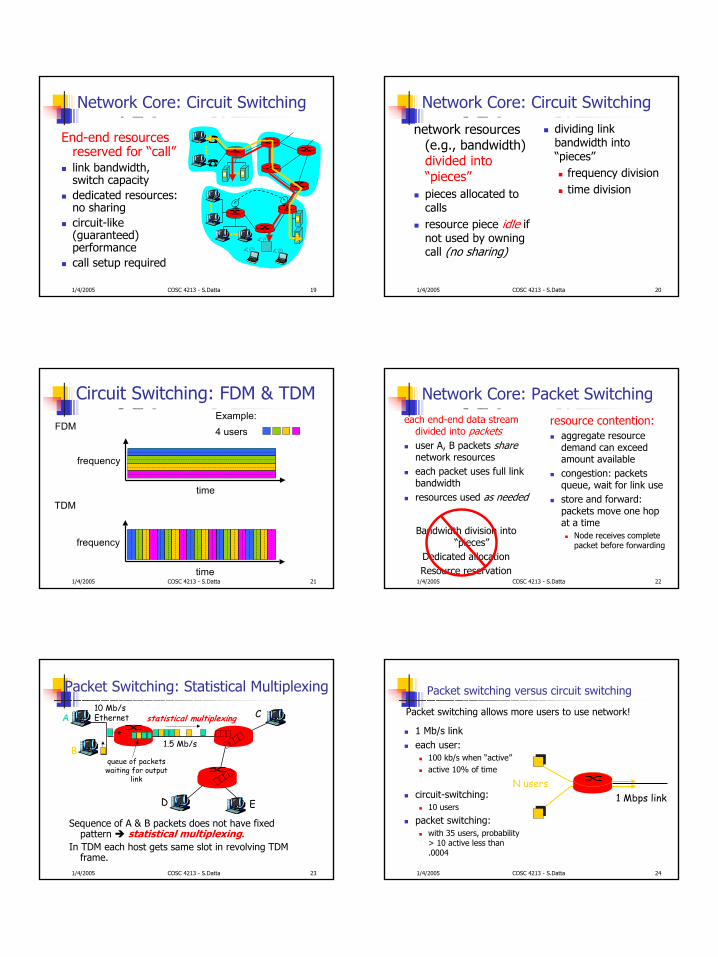
Network Core: Circuit Switching
End-end resources reserved for “call”link bandwidth, switch capacitydedicated resources: no sharingcircuit-like (guaranteed) performancecall setup required
1/4/2005 COSC 4213 - S.Datta 20
Network Core: Circuit Switching
network resources (e.g., bandwidth) divided into “pieces”pieces allocated to callsresource piece idle if not used by owning call (no sharing)
dividing link bandwidth into “pieces”
frequency divisiontime division
1/4/2005 COSC 4213 - S.Datta 21
Circuit Switching: FDM & TDM
FDM
frequency
timeTDM
frequency
time
4 usersExample:
1/4/2005 COSC 4213 - S.Datta 22
Network Core: Packet Switchingeach end-end data stream
divided into packetsuser A, B packets sharenetwork resourceseach packet uses full link bandwidth resources used as needed
resource contention:aggregate resource demand can exceed amount availablecongestion: packets queue, wait for link usestore and forward: packets move one hop at a time
Node receives complete packet before forwarding
Bandwidth division into “pieces”
Dedicated allocationResource reservation
1/4/2005 COSC 4213 - S.Datta 23
Packet Switching: Statistical Multiplexing
Sequence of A & B packets does not have fixed pattern statistical multiplexing.
In TDM each host gets same slot in revolving TDM frame.
A
B
C10 Mb/sEthernet
1.5 Mb/s
D E
statistical multiplexing
queue of packetswaiting for output
link
1/4/2005 COSC 4213 - S.Datta 24
Packet switching versus circuit switching
1 Mb/s linkeach user:
100 kb/s when “active”active 10% of time
circuit-switching: 10 users
packet switching: with 35 users, probability > 10 active less than .0004
Packet switching allows more users to use network!
N users1 Mbps link
5
1/4/2005 COSC 4213 - S.Datta 25
Packet switching versus circuit switching
Great for bursty dataresource sharingsimpler, no call setup
Excessive congestion: packet delay and lossprotocols needed for reliable data transfer, congestion control
Q: How to provide circuit-like behavior?bandwidth guarantees needed for audio/video appsstill an unsolved problem (chapter 6)
Is packet switching a “slam dunk winner?”
1/4/2005 COSC 4213 - S.Datta 26
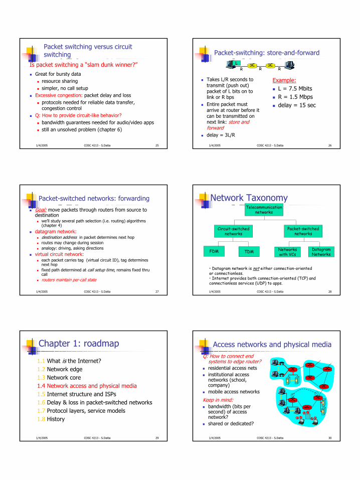
Packet-switching: store-and-forward
Takes L/R seconds to transmit (push out) packet of L bits on to link or R bpsEntire packet must arrive at router before it can be transmitted on next link: store and forwarddelay = 3L/R
Example:L = 7.5 MbitsR = 1.5 Mbpsdelay = 15 sec
R R RL
1/4/2005 COSC 4213 - S.Datta 27
Packet-switched networks: forwarding
Goal: move packets through routers from source to destination
we’ll study several path selection (i.e. routing) algorithms (chapter 4)
datagram network:destination address in packet determines next hoproutes may change during sessionanalogy: driving, asking directions
virtual circuit network:each packet carries tag (virtual circuit ID), tag determines next hopfixed path determined at call setup time, remains fixed thru callrouters maintain per-call state
1/4/2005 COSC 4213 - S.Datta 28
Network TaxonomyTelecommunication
networks
Circuit-switchednetworks
FDM TDM
Packet-switchednetworks
Networkswith VCs
DatagramNetworks
• Datagram network is not either connection-oriented or connectionless.• Internet provides both connection-oriented (TCP) and connectionless services (UDP) to apps.
1/4/2005 COSC 4213 - S.Datta 29
Chapter 1: roadmap
1.1 What is the Internet?1.2 Network edge1.3 Network core1.4 Network access and physical media1.5 Internet structure and ISPs1.6 Delay & loss in packet-switched networks1.7 Protocol layers, service models1.8 History
1/4/2005 COSC 4213 - S.Datta 30
Access networks and physical mediaQ: How to connect end
systems to edge router?residential access netsinstitutional access networks (school, company)mobile access networks
Keep in mind: bandwidth (bits per second) of access network?shared or dedicated?
6
1/4/2005 COSC 4213 - S.Datta 31
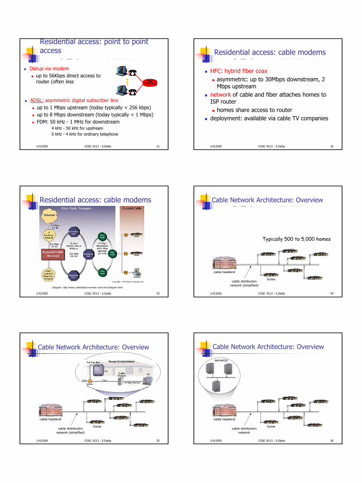
Residential access: point to point access
Dialup via modemup to 56Kbps direct access to router (often less
ADSL: asymmetric digital subscriber lineup to 1 Mbps upstream (today typically < 256 kbps)up to 8 Mbps downstream (today typically < 1 Mbps)FDM: 50 kHz - 1 MHz for downstream
4 kHz - 50 kHz for upstream0 kHz - 4 kHz for ordinary telephone
1/4/2005 COSC 4213 - S.Datta 32
Residential access: cable modems
HFC: hybrid fiber coaxasymmetric: up to 30Mbps downstream, 2 Mbps upstream
network of cable and fiber attaches homes to ISP router
homes share access to router deployment: available via cable TV companies
1/4/2005 COSC 4213 - S.Datta 33
Residential access: cable modems
Diagram: http://www.cabledatacomnews.com/cmic/diagram.html
1/4/2005 COSC 4213 - S.Datta 34
Cable Network Architecture: Overview
home
cable headend
cable distributionnetwork (simplified)
Typically 500 to 5,000 homes
1/4/2005 COSC 4213 - S.Datta 35
Cable Network Architecture: Overview
home
cable headend
cable distributionnetwork (simplified)
1/4/2005 COSC 4213 - S.Datta 36
Cable Network Architecture: Overview
home
cable headend
cable distributionnetwork
server(s)
7
1/4/2005 COSC 4213 - S.Datta 37
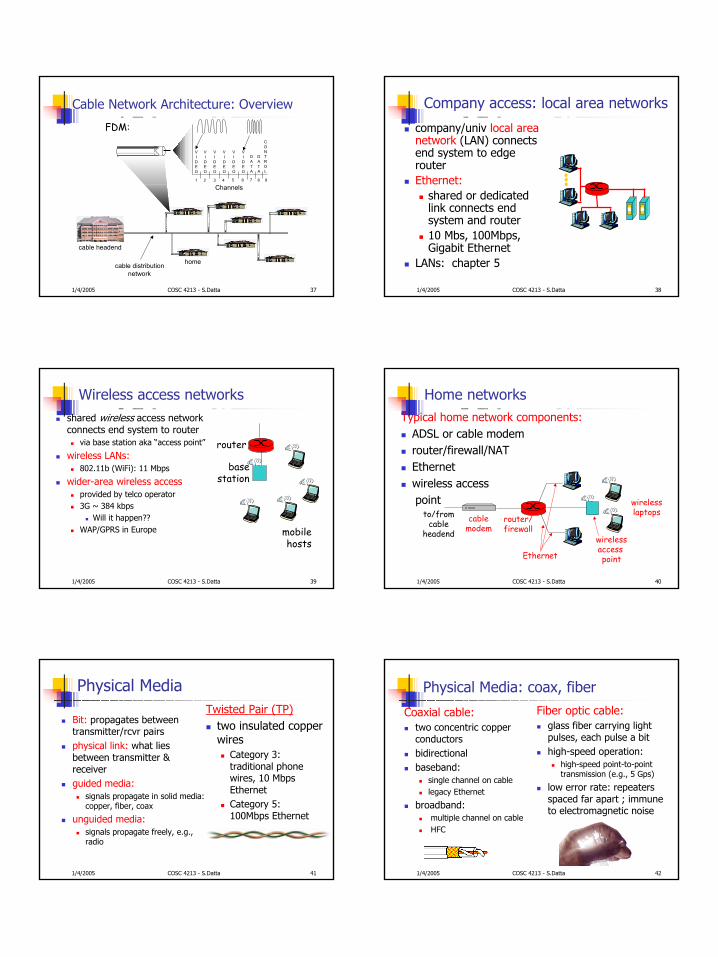
Cable Network Architecture: Overview
home
cable headend
cable distributionnetwork
Channels
VIDEO
VIDEO
VIDEO
VIDEO
VIDEO
VIDEO
DATA
DATA
CONTROL
1 2 3 4 5 6 7 8 9
FDM:
1/4/2005 COSC 4213 - S.Datta 38
Company access: local area networks
company/univ local area network (LAN) connects end system to edge routerEthernet:
shared or dedicated link connects end system and router10 Mbs, 100Mbps, Gigabit Ethernet
LANs: chapter 5
1/4/2005 COSC 4213 - S.Datta 39
Wireless access networksshared wireless access network connects end system to router
via base station aka “access point”
wireless LANs:802.11b (WiFi): 11 Mbps
wider-area wireless accessprovided by telco operator3G ~ 384 kbps
Will it happen??WAP/GPRS in Europe
basestation
mobilehosts
router
1/4/2005 COSC 4213 - S.Datta 40
Home networksTypical home network components:
ADSL or cable modemrouter/firewall/NATEthernetwireless accesspoint
wirelessaccess point
wirelesslaptops
router/firewall
cablemodem
to/fromcable
headend
Ethernet
1/4/2005 COSC 4213 - S.Datta 41
Physical Media
Bit: propagates betweentransmitter/rcvr pairsphysical link: what lies between transmitter & receiverguided media:
signals propagate in solid media: copper, fiber, coax
unguided media:signals propagate freely, e.g., radio
Twisted Pair (TP)two insulated copper wires
Category 3: traditional phone wires, 10 Mbps EthernetCategory 5: 100Mbps Ethernet
1/4/2005 COSC 4213 - S.Datta 42
Physical Media: coax, fiber
Coaxial cable:two concentric copper conductorsbidirectionalbaseband:
single channel on cablelegacy Ethernet
broadband:multiple channel on cableHFC
Fiber optic cable:glass fiber carrying light pulses, each pulse a bithigh-speed operation:
high-speed point-to-point transmission (e.g., 5 Gps)
low error rate: repeaters spaced far apart ; immune to electromagnetic noise
8
1/4/2005 COSC 4213 - S.Datta 43
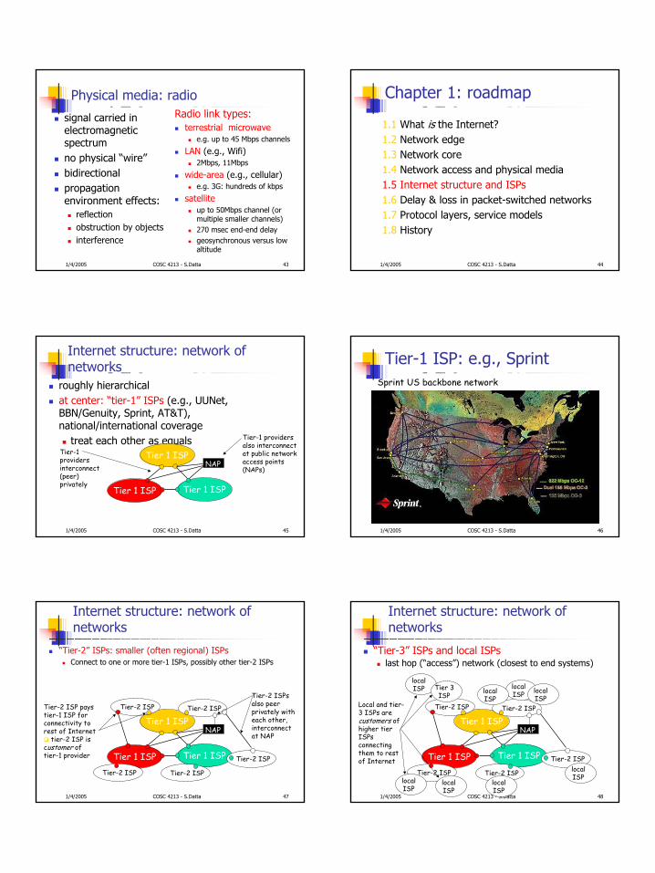
Physical media: radio
signal carried in electromagnetic spectrumno physical “wire”bidirectionalpropagation environment effects:
reflection obstruction by objectsinterference
Radio link types:terrestrial microwave
e.g. up to 45 Mbps channels
LAN (e.g., Wifi)2Mbps, 11Mbps
wide-area (e.g., cellular)e.g. 3G: hundreds of kbps
satelliteup to 50Mbps channel (or multiple smaller channels)270 msec end-end delaygeosynchronous versus low altitude
1/4/2005 COSC 4213 - S.Datta 44
Chapter 1: roadmap
1.1 What is the Internet?1.2 Network edge1.3 Network core1.4 Network access and physical media1.5 Internet structure and ISPs1.6 Delay & loss in packet-switched networks1.7 Protocol layers, service models1.8 History
1/4/2005 COSC 4213 - S.Datta 45
Internet structure: network of networks
roughly hierarchicalat center: “tier-1” ISPs (e.g., UUNet, BBN/Genuity, Sprint, AT&T), national/international coverage
treat each other as equals
Tier 1 ISP
Tier 1 ISP
Tier 1 ISP
Tier-1 providers interconnect (peer) privately
NAP
Tier-1 providers also interconnect at public network access points (NAPs)
1/4/2005 COSC 4213 - S.Datta 46
Tier-1 ISP: e.g., SprintSprint US backbone network
1/4/2005 COSC 4213 - S.Datta 47
Internet structure: network of networks
“Tier-2” ISPs: smaller (often regional) ISPsConnect to one or more tier-1 ISPs, possibly other tier-2 ISPs
Tier 1 ISP
Tier 1 ISP
Tier 1 ISP
NAP
Tier-2 ISPTier-2 ISP
Tier-2 ISP Tier-2 ISP
Tier-2 ISP
Tier-2 ISP pays tier-1 ISP for connectivity to rest of Internet
tier-2 ISP is customer oftier-1 provider
Tier-2 ISPs also peer privately with each other, interconnect at NAP
1/4/2005 COSC 4213 - S.Datta 48
Internet structure: network of networks
“Tier-3” ISPs and local ISPs last hop (“access”) network (closest to end systems)
Tier 1 ISP
Tier 1 ISP
Tier 1 ISP
NAP
Tier-2 ISPTier-2 ISP
Tier-2 ISP Tier-2 ISP
Tier-2 ISP
localISPlocal
ISPlocalISP
localISP
localISP Tier 3
ISP
localISP
localISP
localISP
Local and tier-3 ISPs are customers ofhigher tier ISPsconnecting them to rest of Internet
9
1/4/2005 COSC 4213 - S.Datta 49
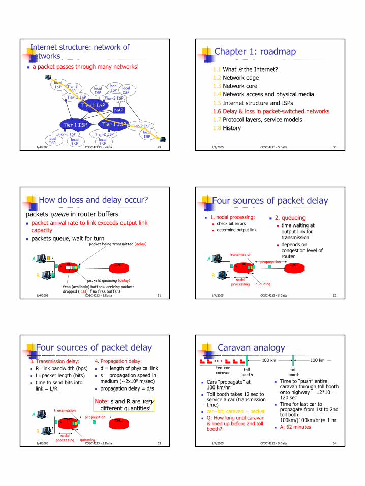
Internet structure: network of networksa packet passes through many networks!
Tier 1 ISP
Tier 1 ISP
Tier 1 ISP
NAP
Tier-2 ISPTier-2 ISP
Tier-2 ISP Tier-2 ISP
Tier-2 ISP
localISPlocal
ISPlocalISP
localISP
localISP Tier 3
ISP
localISP
localISP
localISP
1/4/2005 COSC 4213 - S.Datta 50
Chapter 1: roadmap
1.1 What is the Internet?1.2 Network edge1.3 Network core1.4 Network access and physical media1.5 Internet structure and ISPs1.6 Delay & loss in packet-switched networks1.7 Protocol layers, service models1.8 History
1/4/2005 COSC 4213 - S.Datta 51
How do loss and delay occur?
packets queue in router bufferspacket arrival rate to link exceeds output link capacitypackets queue, wait for turn
A
B
packet being transmitted (delay)
packets queueing (delay)free (available) buffers: arriving packets dropped (loss) if no free buffers
1/4/2005 COSC 4213 - S.Datta 52
Four sources of packet delay
1. nodal processing:check bit errorsdetermine output link
A
B
propagation
transmission
nodalprocessing queueing
2. queueingtime waiting at output link for transmission depends on congestion level of router
1/4/2005 COSC 4213 - S.Datta 53
Four sources of packet delay3. Transmission delay:
R=link bandwidth (bps)L=packet length (bits)time to send bits into link = L/R
4. Propagation delay:d = length of physical links = propagation speed in medium (~2x10⁸ m/sec)propagation delay = d/s
A
B
propagation
transmission
nodalprocessing queueing
Note: s and R are very different quantities!
1/4/2005 COSC 4213 - S.Datta 54
Caravan analogy
Cars “propagate” at 100 km/hrToll booth takes 12 sec to service a car (transmission time)car~bit; caravan ~ packetQ: How long until caravan is lined up before 2nd toll booth?
Time to “push” entire caravan through toll booth onto highway = 12*10 = 120 secTime for last car to propagate from 1st to 2nd toll both: 100km/(100km/hr)= 1 hrA: 62 minutes
toll booth
toll booth
ten-car caravan
100 km 100 km
10
1/4/2005 COSC 4213 - S.Datta 55
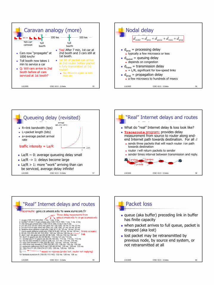
Caravan analogy (more)
Cars now “propagate” at 1000 km/hrToll booth now takes 1 min to service a carQ: Will cars arrive to 2nd booth before all cars serviced at 1st booth?
Yes! After 7 min, 1st car at 2nd booth and 3 cars still at 1st booth.1st bit of packet can arrive at 2nd router before packet is fully transmitted at 1st router!
See Ethernet applet at AWL Web site
toll booth
toll booth
ten-car caravan
100 km 100 km
1/4/2005 COSC 4213 - S.Datta 56
Nodal delay
dproc = processing delaytypically a few microsecs or less
dqueue = queuing delaydepends on congestion
dtrans = transmission delay= L/R, significant for low-speed links
dprop = propagation delaya few microsecs to hundreds of msecs
proptransqueueprocnodal ddddd +++=
1/4/2005 COSC 4213 - S.Datta 57
Queueing delay (revisited)
R=link bandwidth (bps)L=packet length (bits)a=average packet arrival rate
traffic intensity = La/R
La/R ~ 0: average queueing delay smallLa/R -> 1: delays become largeLa/R > 1: more “work” arriving than can be serviced, average delay infinite!
1/4/2005 COSC 4213 - S.Datta 58
“Real” Internet delays and routes
What do “real” Internet delay & loss look like? Traceroute program: provides delay measurement from source to router along end-end Internet path towards destination. For all i:
sends three packets that will reach router i on path towards destinationrouter i will return packets to sendersender times interval between transmission and reply.
3 probes
3 probes
3 probes
1/4/2005 COSC 4213 - S.Datta 59
“Real” Internet delays and routes
1 cs-gw (128.119.240.254) 1 ms 1 ms 2 ms2 border1-rt-fa5-1-0.gw.umass.edu (128.119.3.145) 1 ms 1 ms 2 ms3 cht-vbns.gw.umass.edu (128.119.3.130) 6 ms 5 ms 5 ms4 jn1-at1-0-0-19.wor.vbns.net (204.147.132.129) 16 ms 11 ms 13 ms 5 jn1-so7-0-0-0.wae.vbns.net (204.147.136.136) 21 ms 18 ms 18 ms 6 abilene-vbns.abilene.ucaid.edu (198.32.11.9) 22 ms 18 ms 22 ms7 nycm-wash.abilene.ucaid.edu (198.32.8.46) 22 ms 22 ms 22 ms8 62.40.103.253 (62.40.103.253) 104 ms 109 ms 106 ms9 de2-1.de1.de.geant.net (62.40.96.129) 109 ms 102 ms 104 ms10 de.fr1.fr.geant.net (62.40.96.50) 113 ms 121 ms 114 ms11 renater-gw.fr1.fr.geant.net (62.40.103.54) 112 ms 114 ms 112 ms12 nio-n2.cssi.renater.fr (193.51.206.13) 111 ms 114 ms 116 ms13 nice.cssi.renater.fr (195.220.98.102) 123 ms 125 ms 124 ms14 r3t2-nice.cssi.renater.fr (195.220.98.110) 126 ms 126 ms 124 ms15 eurecom-valbonne.r3t2.ft.net (193.48.50.54) 135 ms 128 ms 133 ms16 194.214.211.25 (194.214.211.25) 126 ms 128 ms 126 ms17 * * *18 * * *19 fantasia.eurecom.fr (193.55.113.142) 132 ms 128 ms 136 ms
traceroute: gaia.cs.umass.edu to www.eurecom.frThree delay measements from gaia.cs.umass.edu to cs-gw.cs.umass.edu
* means no reponse (probe lost, router not replying)
trans-oceaniclink
1/4/2005 COSC 4213 - S.Datta 60
Packet loss
queue (aka buffer) preceding link in buffer has finite capacitywhen packet arrives to full queue, packet is dropped (aka lost)lost packet may be retransmitted by previous node, by source end system, or not retransmitted at all
11
1/4/2005 COSC 4213 - S.Datta 61
Chapter 1: roadmap
1.1 What is the Internet?1.2 Network edge1.3 Network core1.4 Network access and physical media1.5 Internet structure and ISPs1.6 Delay & loss in packet-switched networks1.7 Protocol layers, service models1.8 History
1/4/2005 COSC 4213 - S.Datta 62
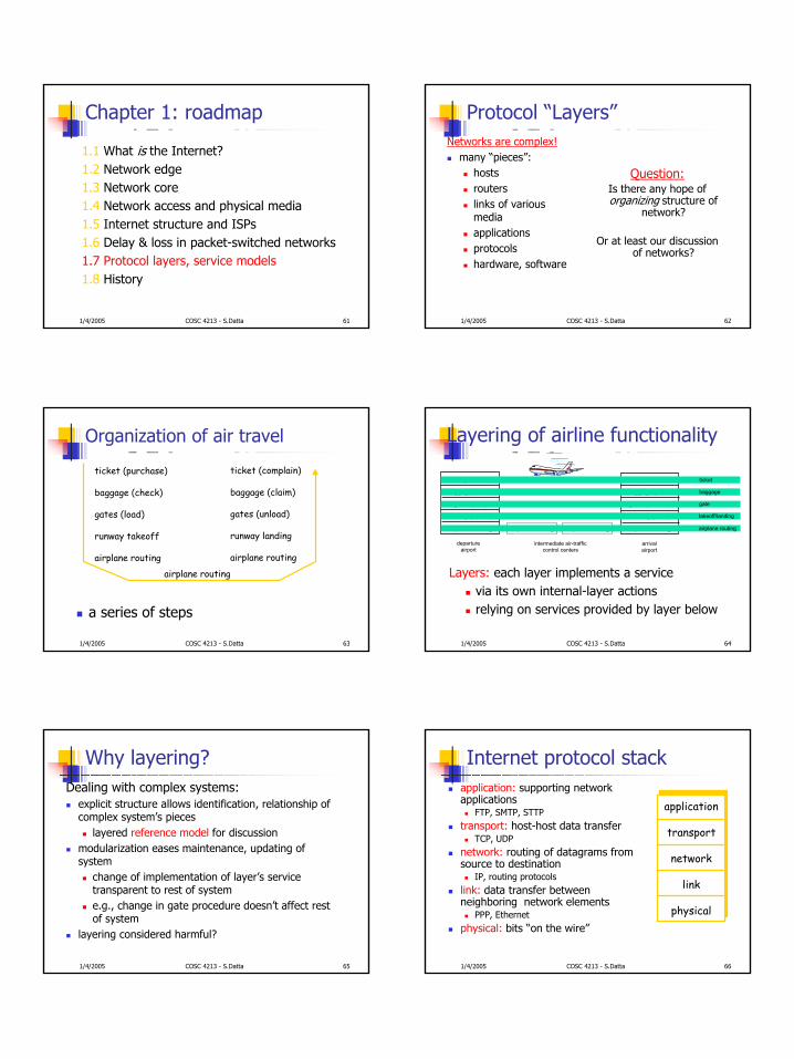
Protocol “Layers”Networks are complex!
many “pieces”:hostsrouterslinks of various mediaapplicationsprotocolshardware, software
Question:Is there any hope of organizing structure of
network?
Or at least our discussion of networks?
1/4/2005 COSC 4213 - S.Datta 63
Organization of air travel
a series of steps
ticket (purchase)
baggage (check)
gates (load)
runway takeoff
airplane routing
ticket (complain)
baggage (claim)
gates (unload)
runway landing
airplane routing
airplane routing
1/4/2005 COSC 4213 - S.Datta 64
ticket (purchase)
baggage (check)
gates (load)
runway (takeoff)
airplane routing
departureairport
arrivalairport
intermediate air-trafficcontrol centers
airplane routing airplane routing
ticket (complain)
baggage (claim
gates (unload)
runway (land)
airplane routing
ticket
baggage
gate
takeoff/landing
airplane routing
Layering of airline functionality
Layers: each layer implements a servicevia its own internal-layer actionsrelying on services provided by layer below
1/4/2005 COSC 4213 - S.Datta 65
Why layering?Dealing with complex systems:
explicit structure allows identification, relationship of complex system’s pieces
layered reference model for discussionmodularization eases maintenance, updating of system
change of implementation of layer’s service transparent to rest of systeme.g., change in gate procedure doesn’t affect rest of system
layering considered harmful?
1/4/2005 COSC 4213 - S.Datta 66
Internet protocol stackapplication: supporting network applications
FTP, SMTP, STTPtransport: host-host data transfer
TCP, UDPnetwork: routing of datagrams from source to destination
IP, routing protocolslink: data transfer between neighboring network elements
PPP, Ethernetphysical: bits “on the wire”
application
transport
network
link
physical
12
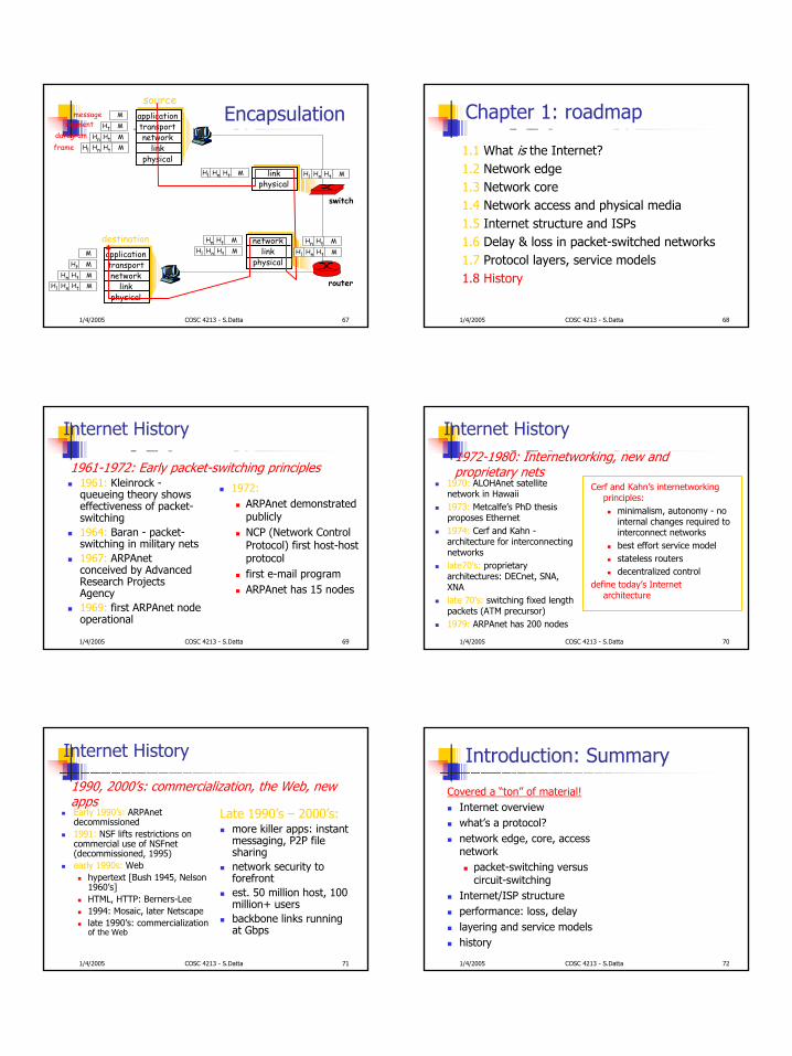
1/4/2005 COSC 4213 - S.Datta 67
messagesegment
datagramframe
sourceapplicationtransportnetwork
linkphysical
HtHnHl MHtHn MHt M
M
destinationapplicationtransportnetwork
linkphysical
HtHnHl MHtHn MHt M
M
networklink
physical
linkphysical
HtHnHl MHtHn M
HtHnHl MHtHn M
HtHnHl M HtHnHl M
router
switch
Encapsulation
1/4/2005 COSC 4213 - S.Datta 68
Chapter 1: roadmap
1.1 What is the Internet?1.2 Network edge1.3 Network core1.4 Network access and physical media1.5 Internet structure and ISPs1.6 Delay & loss in packet-switched networks1.7 Protocol layers, service models1.8 History
1/4/2005 COSC 4213 - S.Datta 69
Internet History
1961: Kleinrock -queueing theory shows effectiveness of packet-switching1964: Baran - packet-switching in military nets1967: ARPAnetconceived by Advanced Research Projects Agency1969: first ARPAnet node operational
1972:ARPAnet demonstrated publiclyNCP (Network Control Protocol) first host-host protocol first e-mail programARPAnet has 15 nodes
1961-1972: Early packet-switching principles
1/4/2005 COSC 4213 - S.Datta 70
Internet History
1970: ALOHAnet satellite network in Hawaii1973: Metcalfe’s PhD thesis proposes Ethernet1974: Cerf and Kahn -architecture for interconnecting networkslate70’s: proprietary architectures: DECnet, SNA, XNAlate 70’s: switching fixed length packets (ATM precursor)1979: ARPAnet has 200 nodes
Cerf and Kahn’s internetworking principles:
minimalism, autonomy - no internal changes required to interconnect networksbest effort service modelstateless routersdecentralized control
define today’s Internet architecture
1972-1980: Internetworking, new and proprietary nets
1/4/2005 COSC 4213 - S.Datta 71
Internet History
Early 1990’s: ARPAnetdecommissioned1991: NSF lifts restrictions on commercial use of NSFnet(decommissioned, 1995)early 1990s: Web
hypertext [Bush 1945, Nelson 1960’s]HTML, HTTP: Berners-Lee1994: Mosaic, later Netscapelate 1990’s: commercializationof the Web
Late 1990’s – 2000’s:more killer apps: instant messaging, P2P file sharingnetwork security to forefrontest. 50 million host, 100 million+ usersbackbone links running at Gbps
1990, 2000’s: commercialization, the Web, new apps
1/4/2005 COSC 4213 - S.Datta 72
Introduction: Summary
Covered a “ton” of material!Internet overviewwhat’s a protocol?network edge, core, access network
packet-switching versus circuit-switching
Internet/ISP structureperformance: loss, delaylayering and service modelshistory
13
1/4/2005 COSC 4213 - S.Datta 73
Next: The Application layer
Reading: Ch 2.