Embed Size (px)
Citation preview
1
COSC 6385
Computer Architecture
- Pipelining
Edgar Gabriel
Spring 2018
Some of the slides are based on a lecture by David Culler, University of California, Berkley
http://www.eecs.berkeley.edu/~culler/courses/cs252-s05
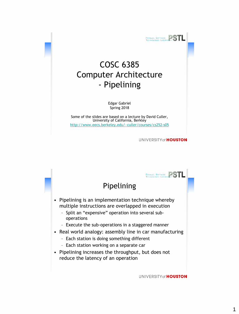
Pipelining
• Pipelining is an implementation technique whereby
multiple instructions are overlapped in execution
– Split an “expensive” operation into several sub-
operations
– Execute the sub-operations in a staggered manner
• Real world analogy: assembly line in car manufacturing
– Each station is doing something different
– Each station working on a separate car
• Pipelining increases the throughput, but does not
reduce the latency of an operation
2
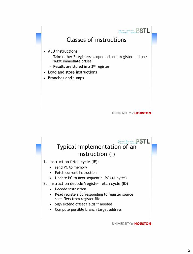
Classes of instructions
• ALU instructions
– Take either 2 registers as operands or 1 register and one
16bit immediate offset
– Results are stored in a 3rd register
• Load and store instructions
• Branches and jumps
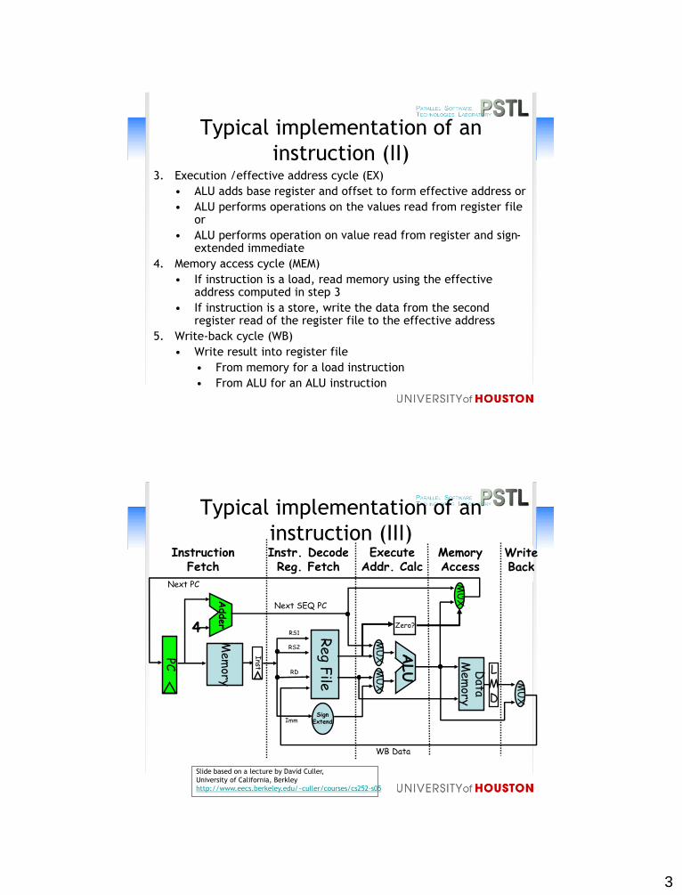
Typical implementation of an
instruction (I)1. Instruction fetch cycle (IF):
• send PC to memory
• Fetch current instruction
• Update PC to next sequential PC (+4 bytes)
2. Instruction decode/register fetch cycle (ID)
• Decode instruction
• Read registers corresponding to register source
specifiers from register file
• Sign extend offset fields if needed
• Compute possible branch target address
3
Typical implementation of an
instruction (II)3. Execution /effective address cycle (EX)
• ALU adds base register and offset to form effective address or
• ALU performs operations on the values read from register file or
• ALU performs operation on value read from register and sign-extended immediate
4. Memory access cycle (MEM)
• If instruction is a load, read memory using the effective address computed in step 3
• If instruction is a store, write the data from the second register read of the register file to the effective address
5. Write-back cycle (WB)
• Write result into register file
• From memory for a load instruction
• From ALU for an ALU instruction
Typical implementation of an
instruction (III)MemoryAccess
WriteBack
InstructionFetch
Instr. DecodeReg. Fetch
ExecuteAddr. Calc
LMD
ALU
MU
X
Mem
ory
Reg
File
MU
XM
UX
Data
Mem
ory
MU
X
SignExtend
4
Adder Zero?
Next SEQ PC
PC
Next PC
WB Data
Inst
RD
RS1
RS2
Imm
Slide based on a lecture by David Culler,
University of California, Berkley
http://www.eecs.berkeley.edu/~culler/courses/cs252-s05
4
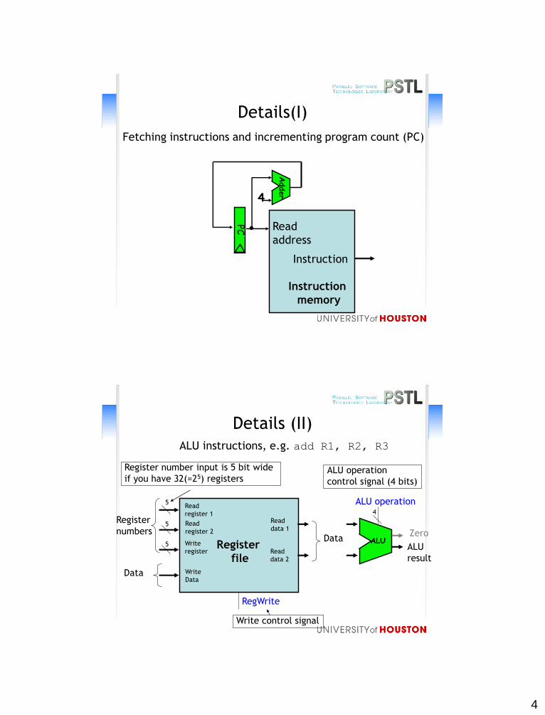
Details(I)
4
Adder
PC Read
address
Instruction
memory
Instruction
Fetching instructions and incrementing program count (PC)
Details (II)
Read
register 1
Register
file
ALU instructions, e.g. add R1, R2, R3
Read
register 2
Write
register
Write
Data
Read
data 1
Read
data 2
5
5
5ALU
Register
numbers
Data
Data
RegWrite
ALU operation4
ALU
result
Zero
Register number input is 5 bit wide
if you have 32(=25) registers
Write control signal
ALU operation
control signal (4 bits)
5
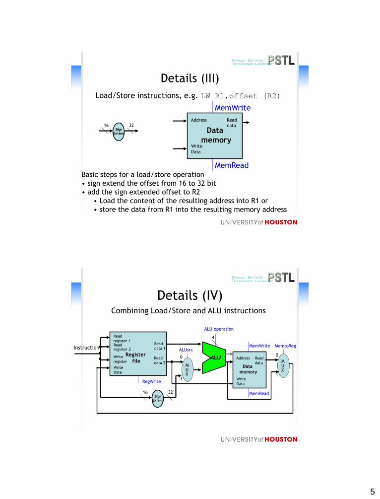
Details (III)
Address
Data
memory
Load/Store instructions, e.g. LW R1,offset (R2)
Write
Data
Read
data
MemRead
MemWrite
SignExtend
16 32
Basic steps for a load/store operation
• sign extend the offset from 16 to 32 bit
• add the sign extended offset to R2
• Load the content of the resulting address into R1 or
• store the data from R1 into the resulting memory address
Details (IV)Combining Load/Store and ALU instructions
Read
register 1
Register
file
Read register 2
Write
register
Write
Data
Read
data 1
Read
data 2
RegWrite
Instruction
SignExtend
16 32
MUX
0
1
ALU
4
Address
Data
memory
Write
Data
Read
data
MemRead
MemWriteALUsrc
MUX
0
1
MemtoReg
ALU operation
6
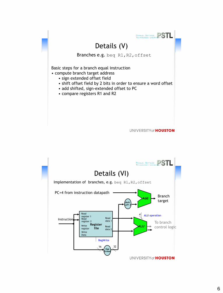
Details (V)Branches e.g. beq R1,R2,offset
Basic steps for a branch equal instruction
• compute branch target address
• sign extended offset field
• shift offset field by 2 bits in order to ensure a word offset
• add shifted, sign-extended offset to PC
• compare registers R1 and R2
Details (VI)Implementation of branches, e.g. beq R1,R2,offset
Read
register 1
Register
file
Read register 2
Write
register
Write
Data
Read
data 1
Read
data 2
RegWrite
SignExtend
16 32
ALU
4 ALU operation
InstructionTo branch
control logic
Shift Left 2
Add
PC+4 from instruction datapathBranch
target
7
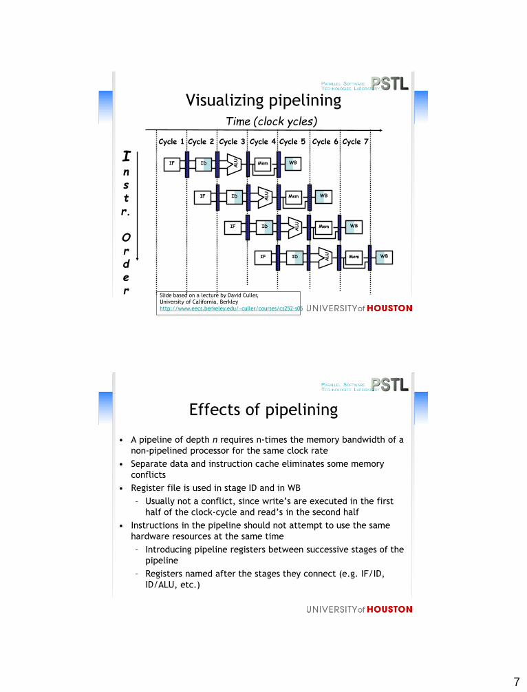
Visualizing pipelining
Instr.
Order
Time (clock ycles)
ID
ALU
MemIF WB
ID
ALU
MemIF WB
ID
ALU
MemIF WB
ID
ALU
MemIF WB
Cycle 1 Cycle 2 Cycle 3 Cycle 4 Cycle 6 Cycle 7Cycle 5
Slide based on a lecture by David Culler,
University of California, Berkley
http://www.eecs.berkeley.edu/~culler/courses/cs252-s05
Effects of pipelining
• A pipeline of depth n requires n-times the memory bandwidth of a
non-pipelined processor for the same clock rate
• Separate data and instruction cache eliminates some memory
conflicts
• Register file is used in stage ID and in WB
– Usually not a conflict, since write’s are executed in the first
half of the clock-cycle and read’s in the second half
• Instructions in the pipeline should not attempt to use the same
hardware resources at the same time
– Introducing pipeline registers between successive stages of the
pipeline
– Registers named after the stages they connect (e.g. IF/ID,
ID/ALU, etc.)
8
MemoryAccess
WriteBack
InstructionFetch
Instr. DecodeReg. Fetch
ExecuteAddr.Calc
ALU
Mem
ory
Reg
File
MU
XM
UX
Data
Mem
ory
MU
X
SignExtend
Zero?
IF/I
D
ID/E
X
MEM
/WB
EX/M
EM
4
Adder
Next SEQ PC Next SEQ PC
RD RD RD
Next PC
Addre
ss
RS1
RS2
Imm
MU
X
Slide based on a lecture by David Culler,
University of California, Berkley
http://www.eecs.berkeley.edu/~culler/courses/cs252-s05
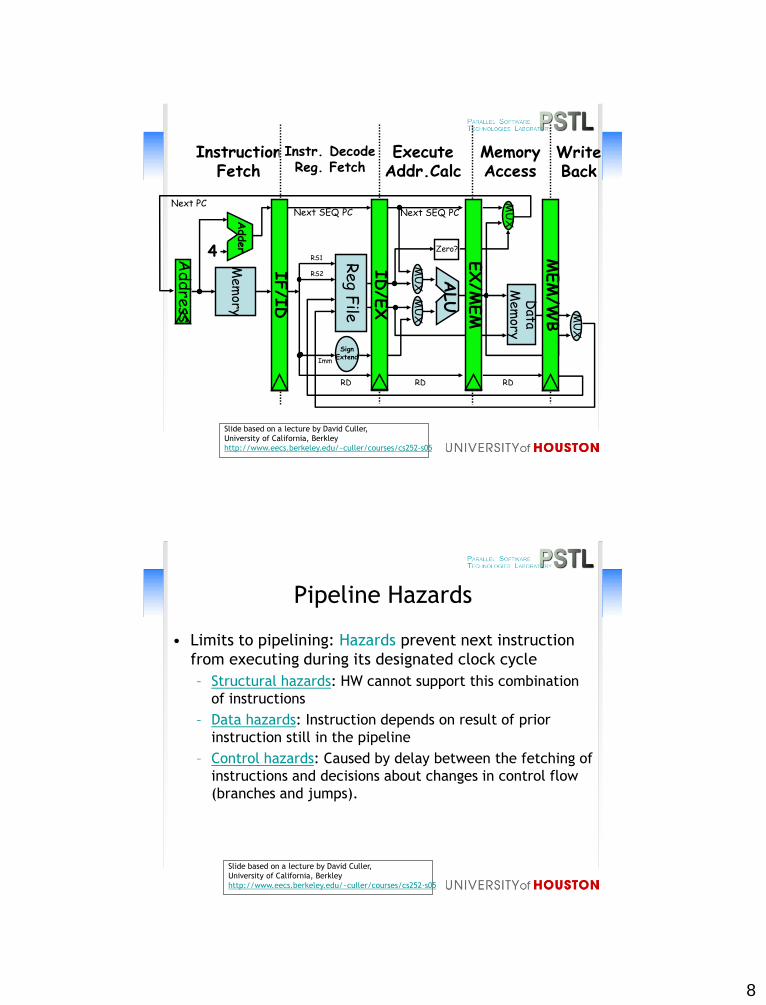
Pipeline Hazards
• Limits to pipelining: Hazards prevent next instruction
from executing during its designated clock cycle
– Structural hazards: HW cannot support this combination
of instructions
– Data hazards: Instruction depends on result of prior
instruction still in the pipeline
– Control hazards: Caused by delay between the fetching of
instructions and decisions about changes in control flow
(branches and jumps).
Slide based on a lecture by David Culler,
University of California, Berkley
http://www.eecs.berkeley.edu/~culler/courses/cs252-s05
9
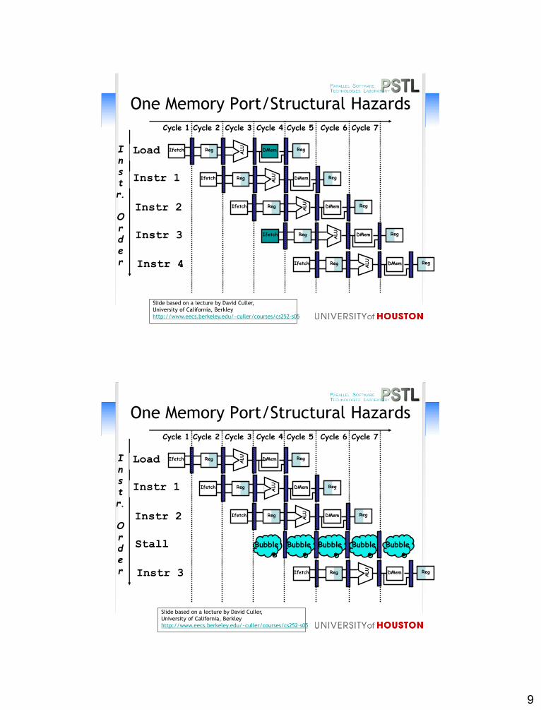
One Memory Port/Structural Hazards
Instr.
Order
Load
Instr 1
Instr 2
Instr 3
Instr 4
Reg
ALU
DMemIfetch Reg
Reg
ALU
DMemIfetch Reg
Reg
ALU
DMemIfetch Reg
Reg
ALU
DMemIfetch Reg
Cycle 1 Cycle 2 Cycle 3 Cycle 4 Cycle 6 Cycle 7Cycle 5
Reg
ALU
DMemIfetch Reg
Slide based on a lecture by David Culler,
University of California, Berkley
http://www.eecs.berkeley.edu/~culler/courses/cs252-s05
One Memory Port/Structural Hazards
Instr.
Order
Load
Instr 1
Instr 2
Stall
Instr 3
Reg
ALU
DMemIfetch Reg
Reg
ALU
DMemIfetch Reg
Reg
ALU
DMemIfetch Reg
Cycle 1 Cycle 2 Cycle 3 Cycle 4 Cycle 6 Cycle 7Cycle 5
Reg
ALU
DMemIfetch Reg
Bubble Bubble Bubble BubbleBubble
Slide based on a lecture by David Culler,
University of California, Berkley
http://www.eecs.berkeley.edu/~culler/courses/cs252-s05
10
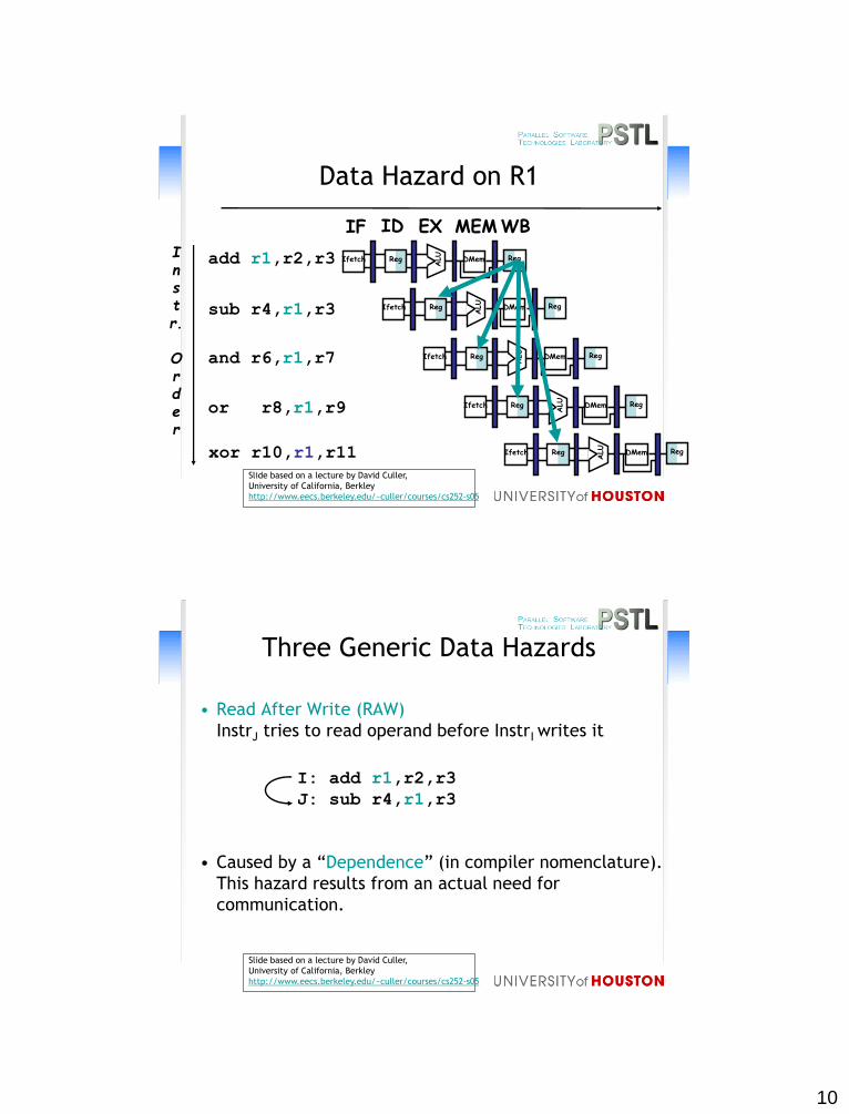
Instr.
Order
add r1,r2,r3
sub r4,r1,r3
and r6,r1,r7
or r8,r1,r9
xor r10,r1,r11
Reg
ALU
DMemIfetch Reg
Reg
ALU
DMemIfetch Reg
Reg
ALU
DMemIfetch Reg
Reg
ALU
DMemIfetch Reg
Reg
ALU
DMemIfetch Reg
Data Hazard on R1
IF ID EX MEMWB
Slide based on a lecture by David Culler,
University of California, Berkley
http://www.eecs.berkeley.edu/~culler/courses/cs252-s05
• Read After Write (RAW)
InstrJ tries to read operand before InstrI writes it
• Caused by a “Dependence” (in compiler nomenclature).
This hazard results from an actual need for
communication.
Three Generic Data Hazards
I: add r1,r2,r3
J: sub r4,r1,r3
Slide based on a lecture by David Culler,
University of California, Berkley
http://www.eecs.berkeley.edu/~culler/courses/cs252-s05
11
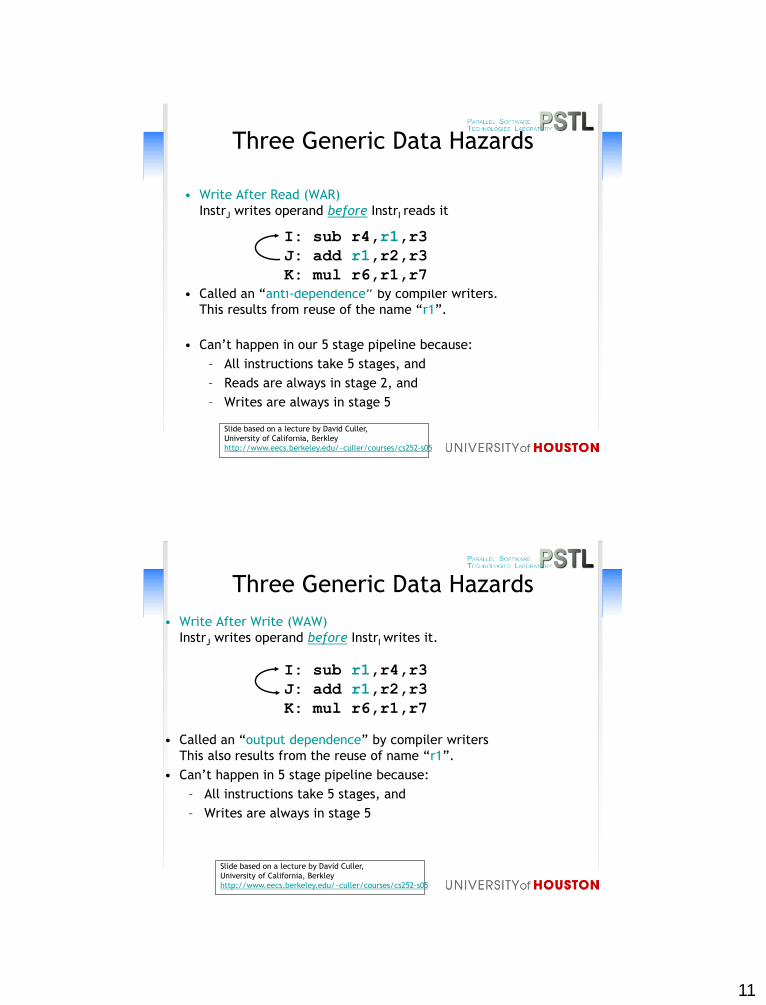
• Write After Read (WAR)
InstrJ writes operand before InstrI reads it
• Called an “anti-dependence” by compiler writers.
This results from reuse of the name “r1”.
• Can’t happen in our 5 stage pipeline because:
– All instructions take 5 stages, and
– Reads are always in stage 2, and
– Writes are always in stage 5
I: sub r4,r1,r3
J: add r1,r2,r3
K: mul r6,r1,r7
Three Generic Data Hazards
Slide based on a lecture by David Culler,
University of California, Berkley
http://www.eecs.berkeley.edu/~culler/courses/cs252-s05
Three Generic Data Hazards
• Write After Write (WAW)
InstrJ writes operand before InstrI writes it.
• Called an “output dependence” by compiler writers
This also results from the reuse of name “r1”.
• Can’t happen in 5 stage pipeline because:
– All instructions take 5 stages, and
– Writes are always in stage 5
I: sub r1,r4,r3
J: add r1,r2,r3
K: mul r6,r1,r7
Slide based on a lecture by David Culler,
University of California, Berkley
http://www.eecs.berkeley.edu/~culler/courses/cs252-s05
12
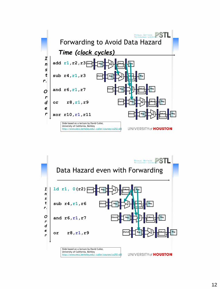
Time (clock cycles)
Forwarding to Avoid Data Hazard
Inst
r.
Order
add r1,r2,r3
sub r4,r1,r3
and r6,r1,r7
or r8,r1,r9
xor r10,r1,r11
Reg
ALU
DMemIfetch Reg
Reg
ALU
DMemIfetch Reg
Reg
ALU
DMemIfetch Reg
Reg
ALU
DMemIfetch Reg
Reg
ALU
DMemIfetch Reg
Slide based on a lecture by David Culler,
University of California, Berkley
http://www.eecs.berkeley.edu/~culler/courses/cs252-s05
Instr.
Order
ld r1, 0(r2)
sub r4,r1,r6
and r6,r1,r7
or r8,r1,r9
Data Hazard even with Forwarding
Reg
ALU
DMemIfetch Reg
Reg
ALU
DMemIfetch Reg
Reg
ALU
DMemIfetch Reg
Reg
ALU
DMemIfetch Reg
Slide based on a lecture by David Culler,
University of California, Berkley
http://www.eecs.berkeley.edu/~culler/courses/cs252-s05
13
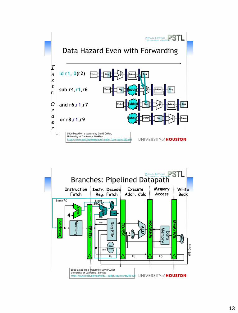
Data Hazard Even with Forwarding
or r8,r1,r9
Instr.
Order
ld r1, 0(r2)
sub r4,r1,r6
and r6,r1,r7
Reg
ALU
DMemIfetch Reg
RegIfetch
ALU
DMem RegBubble
Ifetch
ALU
DMem RegBubble Reg
Ifetch
ALU
DMemBubble Reg
Slide based on a lecture by David Culler,
University of California, Berkley
http://www.eecs.berkeley.edu/~culler/courses/cs252-s05
Adder
IF/I
D
Branches: Pipelined DatapathMemoryAccess
WriteBack
InstructionFetch
Instr. DecodeReg. Fetch
ExecuteAddr. Calc
ALU
Mem
ory
Reg
File
MU
X
Data
Mem
ory
MU
X
SignExtend
Zero?
MEM
/WB
EX/M
EM
4
Adder
Next SEQ PC
RD RD RD WB
Dat
a
Next PC
Addre
ss
RS1
RS2
Imm
MU
X
ID/E
X
Slide based on a lecture by David Culler,
University of California, Berkley
http://www.eecs.berkeley.edu/~culler/courses/cs252-s05
14
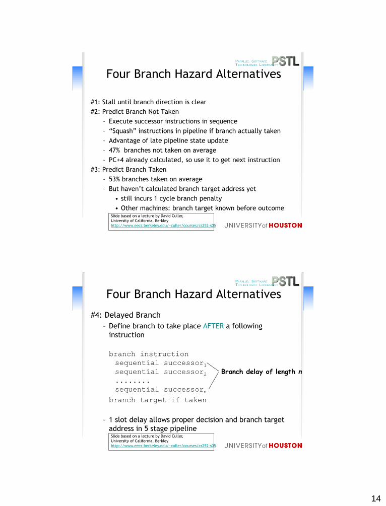
Four Branch Hazard Alternatives
#1: Stall until branch direction is clear
#2: Predict Branch Not Taken
– Execute successor instructions in sequence
– “Squash” instructions in pipeline if branch actually taken
– Advantage of late pipeline state update
– 47% branches not taken on average
– PC+4 already calculated, so use it to get next instruction
#3: Predict Branch Taken
– 53% branches taken on average
– But haven’t calculated branch target address yet
• still incurs 1 cycle branch penalty
• Other machines: branch target known before outcomeSlide based on a lecture by David Culler,
University of California, Berkley
http://www.eecs.berkeley.edu/~culler/courses/cs252-s05
Four Branch Hazard Alternatives
#4: Delayed Branch
– Define branch to take place AFTER a following
instruction
branch instruction
sequential successor1sequential successor2........
sequential successorn
branch target if taken
– 1 slot delay allows proper decision and branch target
address in 5 stage pipeline
Branch delay of length n
Slide based on a lecture by David Culler,
University of California, Berkley
http://www.eecs.berkeley.edu/~culler/courses/cs252-s05
15
Delayed Branch
• Where to get instructions to fill branch delay slot?
– Before branch instruction
– From the target address: only valuable when branch
taken
– From fall through: only valuable when branch not taken
• Compiler effectiveness for single branch delay slot:
– Fills about 60% of branch delay slots
– About 80% of instructions executed in branch delay slots
useful in computation
Slide based on a lecture by David Culler,
University of California, Berkley
http://www.eecs.berkeley.edu/~culler/courses/cs252-s05