Embed Size (px)
Citation preview
COSMOSDRIVER
SERIES 3000
USE AND MAINTENANCE MANUAL
COSMOS DRIVER SERIES 3000 - USE AND MAINTENANCE MANUAL
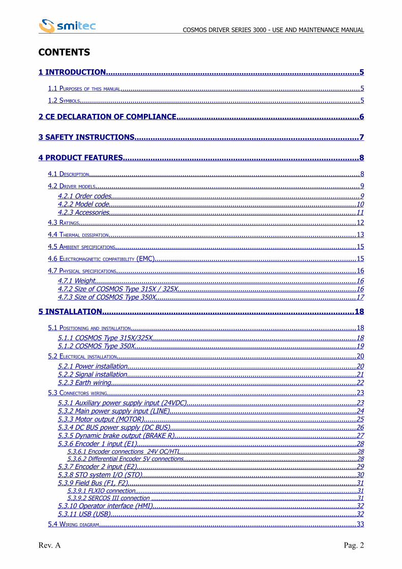
CONTENTS
1 INTRODUCTION .............................................................................................................. 5
1.1 PURPOSES OF THIS MANUAL .................................................................................................................... 5
1.2 SYMBOLS ........................................................................................................................................ 5
2 CE DECLARATION OF COMPLIANCE ............................................................................... 6
3 SAFETY INSTRUCTIONS ................................................................................................. 7
4 PRODUCT FEATURES ...................................................................................................... 8
4.1 DESCRIPTION ................................................................................................................................... 8
4.2 DRIVER MODELS ................................................................................................................................ 9 4.2.1 Order codes .......................................................................................................................... 9 4.2.2 Model code .......................................................................................................................... 10 4.2.3 Accessories ......................................................................................................................... 11
4.3 RATINGS ...................................................................................................................................... 12
4.4 THERMAL DISSIPATION ........................................................................................................................ 13
4.5 AMBIENT SPECIFICATIONS ..................................................................................................................... 15
4.6 ELECTROMAGNETIC COMPATIBILITY (EMC) .................................................................................................. 15
4.7 PHYSICAL SPECIFICATIONS .................................................................................................................... 16 4.7.1 Weight ................................................................................................................................ 16 4.7.2 Size of COSMOS Type 315X / 325X ........................................................................................ 16 4.7.3 Size of COSMOS Type 350X .................................................................................................. 17
5 INSTALLATION ............................................................................................................. 18
5.1 POSITIONING AND INSTALLATION ............................................................................................................. 18 5.1.1 COSMOS Type 315X/325X .................................................................................................... 18 5.1.2 COSMOS Type 350X ............................................................................................................. 19
5.2 ELECTRICAL INSTALLATION .................................................................................................................... 20 5.2.1 Power installation ................................................................................................................ 20 5.2.2 Signal installation ................................................................................................................. 21 5.2.3 Earth wiring ........................................................................................................................ 22
5.3 CONNECTORS WIRING ......................................................................................................................... 23 5.3.1 Auxiliary power supply input (24VDC) ................................................................................... 23 5.3.2 Main power supply input (LINE) ............................................................................................ 24 5.3.3 Motor output (MOTOR) ........................................................................................................ 25 5.3.4 DC BUS power supply (DC BUS) ........................................................................................... 26 5.3.5 Dynamic brake output (BRAKE R) ......................................................................................... 27 5.3.6 Encoder 1 input (E1) ............................................................................................................ 28
5.3.6.1 Encoder connections 24V OC/HTL ................................................................................................ 28 5.3.6.2 Differential Encoder 5V connections ............................................................................................... 28
5.3.7 Encoder 2 input (E2) ............................................................................................................ 29 5.3.8 STO system I/O (STO) ......................................................................................................... 30 5.3.9 Field Bus (F1, F2) ................................................................................................................ 31
5.3.9.1 FLXIO connection ......................................................................................................................... 31 5.3.9.2 SERCOS III connection ................................................................................................................ 31
5.3.10 Operator interface (HMI) .................................................................................................... 32 5.3.11 USB (USB) ......................................................................................................................... 32
5.4 WIRING DIAGRAM ............................................................................................................................. 33
Rev. A Pag. 2
COSMOS DRIVER SERIES 3000 - USE AND MAINTENANCE MANUAL
5.5 CHOICE OF THE WIRES AND FUSES ........................................................................................................... 34
6 SAFETY INTEGRATED SYSTEM ..................................................................................... 35
6.1 DESCRIPTION ................................................................................................................................. 35
6.2 OPERATION ................................................................................................................................... 35 6.2.1 Signals ................................................................................................................................ 35 6.2.2 Electrical specifications ......................................................................................................... 35 6.2.3 System status ...................................................................................................................... 36 6.2.4 Intervention times ............................................................................................................... 36
7 OPERATOR INTERFACE ................................................................................................. 37
7.1 FUNCTION OF THE KEYS ...................................................................................................................... 37
7.2 INTERACTION .................................................................................................................................. 38 7.2.1 Status message ................................................................................................................... 38
7.2.1.1 Field bus Sercos III ....................................................................................................................... 38 7.2.1.2 Field bus FlxIO ............................................................................................................................. 39
7.2.2 Access level ......................................................................................................................... 39 7.2.3 Main menu .......................................................................................................................... 39 7.2.4 Measure menu ..................................................................................................................... 40
7.2.4.1 Models for brushless motor ........................................................................................................... 40 7.2.4.2 Models for asynchronous motor ..................................................................................................... 41
7.2.5 Status menu ........................................................................................................................ 42 7.2.6 Control menu ....................................................................................................................... 42
7.2.6.1 Models for brushless motor ........................................................................................................... 42 7.2.6.2 Modells for asynchronous motor .................................................................................................... 45
7.2.7 Motor menu ......................................................................................................................... 47 7.2.7.1 Models for brushless motor ............................................................................................................ 47 7.2.7.2 Models for asynchronous motor ..................................................................................................... 48
7.2.8 Service menu ....................................................................................................................... 49 7.2.8.1 Models for brushless motor ........................................................................................................... 49 7.2.8.2 Models for asynchronous motor ..................................................................................................... 49
7.2.9 External brake menu ............................................................................................................ 50 7.2.9.1 Models for brushless motor ........................................................................................................... 50 7.2.9.2 Models for asynchronous motor ..................................................................................................... 50
7.2.10 Driver menu ....................................................................................................................... 51 7.2.10.1 Models for brushless motor ......................................................................................................... 51 7.2.10.2 Models for asynchronous motor ................................................................................................... 52
7.2.11 Ethernet menu ................................................................................................................... 52 7.2.12 Encoder menu ................................................................................................................... 53 7.2.13 VISIO menu ....................................................................................................................... 54
7.2.13.1 Models for brushless motor ......................................................................................................... 54 7.2.13.2 Models for asynchronous motor ................................................................................................... 54
8 LEDS AND ADDRESS ..................................................................................................... 55
8.1 ADDRESS SETTING ............................................................................................................................ 56
8.2 LEDS “LINE” AND “24VDC” ............................................................................................................ 57
8.3 LEDS “FLT” AND “STS” ................................................................................................................. 57
8.4 LEDS I1, I2 AND TO ..................................................................................................................... 57
8.5 LEDS A AND L .............................................................................................................................. 57
8.6 LEDS FBS .................................................................................................................................. 58 8.6.1 Field bus FlxIO .................................................................................................................... 58 8.6.2 Field bus Sercos III .............................................................................................................. 58 8.6.3 Field bus Ethernet IP ........................................................................................................... 58
9 ERROR CODES ............................................................................................................... 59
Rev. A Pag. 3
COSMOS DRIVER SERIES 3000 - USE AND MAINTENANCE MANUAL
9.1 INTERNAL ERRORS ............................................................................................................................ 59
9.2 CONTROL ERRORS ............................................................................................................................. 60 9.2.1 Models for brushless motor .................................................................................................. 60 9.2.2 Models for asynchronous motor ............................................................................................ 62
9.3 WARNINGS .................................................................................................................................... 63 9.3.1 Models for brushless motor .................................................................................................. 63 9.3.2 Models for asynchronous motor ............................................................................................ 63
Rev. A Pag. 4
COSMOS DRIVER SERIES 3000 - USE AND MAINTENANCE MANUAL
1 INTRODUCTION
1.1 Purposes of this manual
This manual contains all necessary information for safety, installation, use and maintenance of drivers COSMOS 3000.
1.2 Symbols
Symbols used in this manual:
Danger: high voltage
General warning
Rev. A Pag. 5
COSMOS DRIVER SERIES 3000 - USE AND MAINTENANCE MANUAL
2 CE DECLARATION OF COMPLIANCE
The driver for brushless motors COSMOS-3000 complies with the provisions of the Laws based on the followingdirectives:
LOW VOLTAGE DIRECTIVE: 2006/95/CE
The directives are in accordance with the following harmonised standards:ELECTRICAL EQUIPMENT OF MACHINES: EN60204-1
Rev. A Pag. 6
COSMOS DRIVER SERIES 3000 - USE AND MAINTENANCE MANUAL
3 SAFETY INSTRUCTIONS
The high voltage of some accessories and components in the driver might cause electrocution, if the usercame into contact with them. The connectors with a dangerous voltage are: MOTOR, BRAKE R, DC BUS, LINE.
There are some condensers inside the driver which maintain a dangerous voltage for at least 10 minutes afterswitching them off. Before starting any operation, make sure that the driver has been switched off at least 10minutes earlier and that the motor is still.
Never use the driver if the container is not fully assembled.
Avoid any metal components (screws, electrical cables…) fall into the driver during the installation, becausethey might cause short-circuits.
The driver is an electric generator. The running speed becomes electric potential. High voltage is alreadygenerated at 300 rpm.
The improper use of the motors and/or the wrong assembly of the mechanical components may seriouslyinjure the user.
Make sure that the personnel is competent and has been informed about the risks he may run and how toavoid them.
Avoid the contact with the driver rear metal surfaces, because they may become very hot during operation.
Rev. A Pag. 7
COSMOS DRIVER SERIES 3000 - USE AND MAINTENANCE MANUAL
4 PRODUCT FEATURES
4.1 Description
The series of drivers COSMOS-3000 has been designed for motors with sinusoidal electromotive force and three-phaseasynchronous motors.
The core of the power section is an intelligent IGBT module (IPM), featuring the necessary protections that guarantee anextreme reliability and efficiency, besides reducing the external components.
The control logic is implemented by a 32-bit micro-controller, equipped with a set of instructions optimized for speed andspecialized in controlling precision motors.
Thanks to their design features, the drivers can be considered as of digital type, because they are completely controlledby the micro-controller. As a consequence, the drivers COSMOS-3000 are very flexible appliances which can be resetthrough a software and are open to all improvements offered by the new technologies in the future.
The driver parameters setting and the status notification are controlled by a field bus and/or, depending on the model,by a series of LEDs and by a special removable keyboard called VISIO 3000.
Last, but not least, the mechanical compactness makes of the COSMOS-3000 strong appliances which can be easilyintegrated with the fixing systems of the machine electrical panels.
Rev. A Pag. 8
COSMOS DRIVER SERIES 3000 - USE AND MAINTENANCE MANUAL
4.2 Driver models
The series of drivers COSMOS 3000 includes appliances with different powers, different field buses and other differentfeatures; potentially, it is possible to create the most appropriate model for your needs.
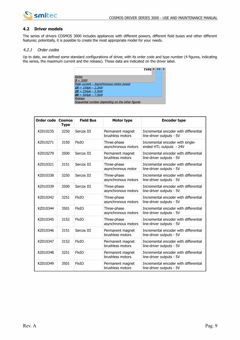
4.2.1 Order codes
Up to date, we defined some standard configurations of driver, with its order code and type number (4 figures, indicatingthe series, the maximum current and the release). These data are indicated on the driver label.
Order code CosmosType
Field Bus Motor type Encoder type
KZ010235 3250 Sercos III Permanent magnet brushless motors
Incremental encoder with differential line-driver outputs - 5V
KZ010271 3150 FlxIO Three-phase asynchronous motors
Incremental encoder with single-ended HTL outputs - 24V
KZ010279 3500 Sercos III Permanent magnet brushless motors
Incremental encoder with differential line-driver outputs - 5V
KZ010321 3151 Sercos III Three-phaseasynchronous motor
Incremental encoder with differential line-driver outputs - 5V
KZ010338 3250 Sercos III Three-phaseasynchronous motors
Incremental encoder with differential line-driver outputs - 5V
KZ010339 3500 Sercos III Three-phaseasynchronous motors
Incremental encoder with differential line-driver outputs - 5V
KZ010342 3251 FlxIO Three-phaseasynchronous motors
Incremental encoder with differential line-driver outputs - 5V
KZ010344 3501 FlxIO Three-phaseasynchronous motors
Incremental encoder with differential line-driver outputs - 5V
KZ010345 3152 FlxIO Three-phaseasynchronous motors
Incremental encoder with differential line-driver outputs - 5V
KZ010346 3151 Sercos III Permanent magnet brushless motors
Incremental encoder with differential line-driver outputs - 5V
KZ010347 3152 FlxIO Permanent magnet brushless motors
Incremental encoder with differential line-driver outputs - 5V
KZ010348 3251 FlxIO Permanent magnet brushless motors
Incremental encoder with differential line-driver outputs - 5V
KZ010349 3501 FlxIO Permanent magnet brushless motors
Incremental encoder with differential line-driver outputs - 5V
Rev. A Pag. 9
TYPE * ** *
Series3 = 3000Peak current – Asynchronous motor power15 = 15Apk – 2.2kW25 = 25Apk – 5.5kW50 = 50Apk – 7.5kWReleaseSequential number depending on the other figures
COSMOS DRIVER SERIES 3000 - USE AND MAINTENANCE MANUAL
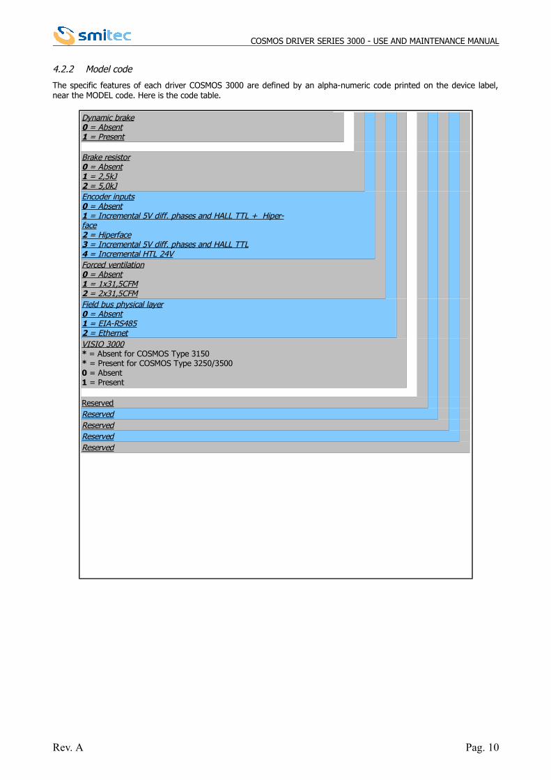
4.2.2 Model code
The specific features of each driver COSMOS 3000 are defined by an alpha-numeric code printed on the device label,near the MODEL code. Here is the code table.
Rev. A Pag. 10
ReservedReservedReservedReservedReserved
Dynamic brake0 = Absent1 = Present
Brake resistor0 = Absent1 = 2,5kJ2 = 5,0kJEncoder inputs0 = Absent1 = Incremental 5V diff. phases and HALL TTL + Hiper-face2 = Hiperface3 = Incremental 5V diff. phases and HALL TTL4 = Incremental HTL 24VForced ventilation0 = Absent1 = 1x31,5CFM2 = 2x31,5CFMField bus physical layer0 = Absent1 = EIA-RS4852 = EthernetVISIO 3000* = Absent for COSMOS Type 3150* = Present for COSMOS Type 3250/3500 0 = Absent1 = Present
COSMOS DRIVER SERIES 3000 - USE AND MAINTENANCE MANUAL
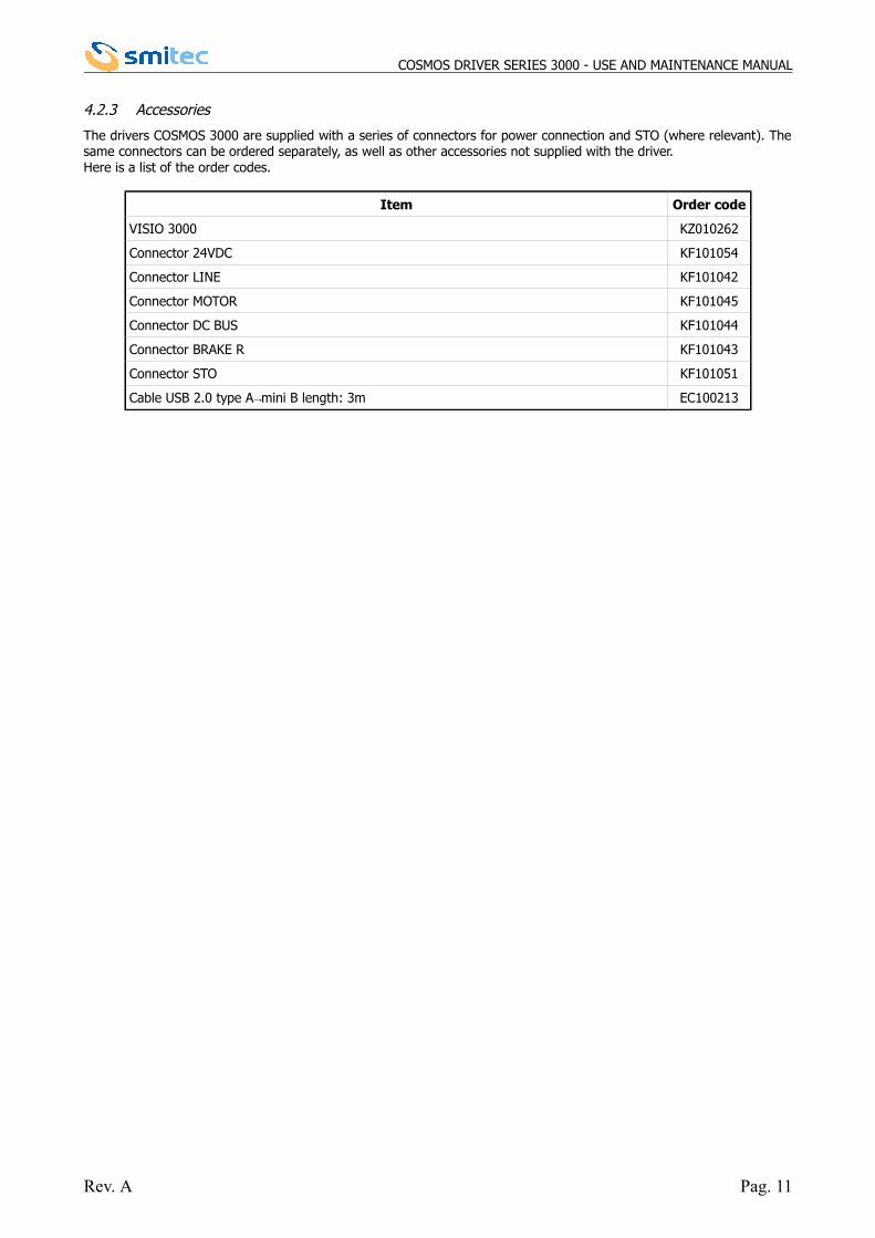
4.2.3 Accessories
The drivers COSMOS 3000 are supplied with a series of connectors for power connection and STO (where relevant). Thesame connectors can be ordered separately, as well as other accessories not supplied with the driver. Here is a list of the order codes.
Item Order code
VISIO 3000 KZ010262
Connector 24VDC KF101054
Connector LINE KF101042
Connector MOTOR KF101045
Connector DC BUS KF101044
Connector BRAKE R KF101043
Connector STO KF101051
Cable USB 2.0 type A mini B length: 3m→ EC100213
Rev. A Pag. 11
COSMOS DRIVER SERIES 3000 - USE AND MAINTENANCE MANUAL
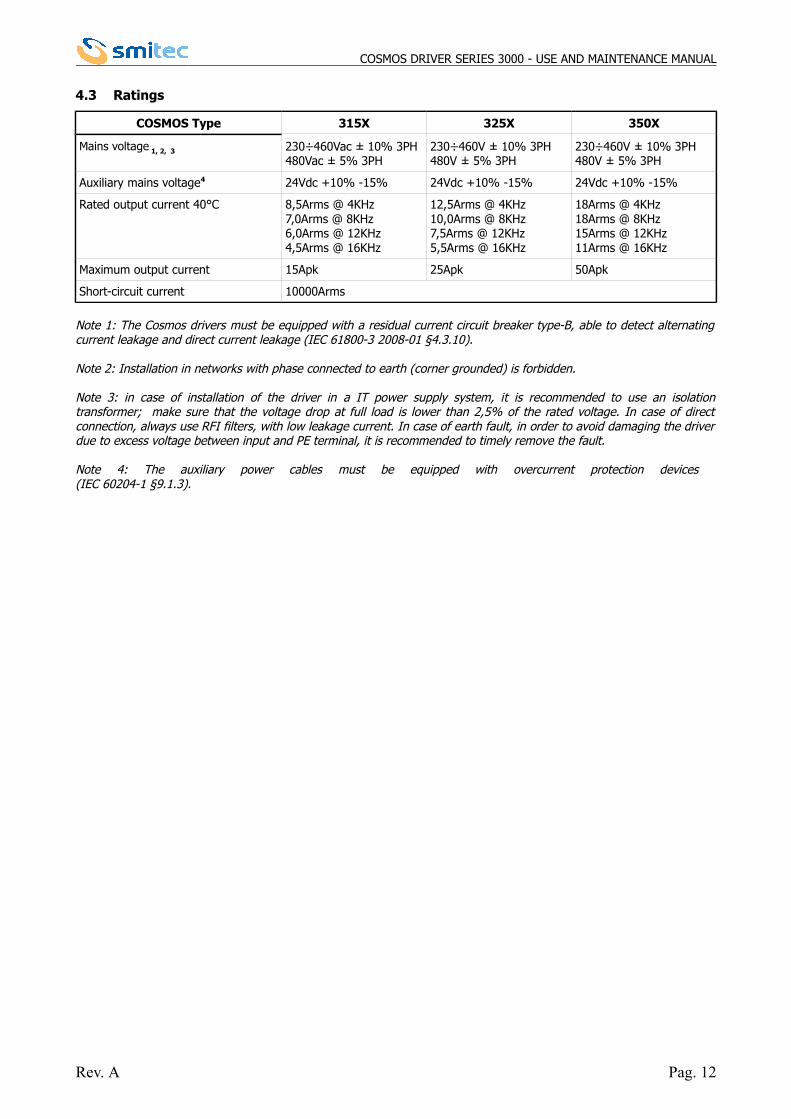
4.3 Ratings
COSMOS Type 315X 325X 350X
Mains voltage 1, 2, 3 230÷460Vac ± 10% 3PH480Vac ± 5% 3PH
230÷460V ± 10% 3PH480V ± 5% 3PH
230÷460V ± 10% 3PH480V ± 5% 3PH
Auxiliary mains voltage4 24Vdc +10% -15% 24Vdc +10% -15% 24Vdc +10% -15%
Rated output current 40°C 8,5Arms @ 4KHz7,0Arms @ 8KHz6,0Arms @ 12KHz4,5Arms @ 16KHz
12,5Arms @ 4KHz10,0Arms @ 8KHz7,5Arms @ 12KHz5,5Arms @ 16KHz
18Arms @ 4KHz18Arms @ 8KHz15Arms @ 12KHz11Arms @ 16KHz
Maximum output current 15Apk 25Apk 50Apk
Short-circuit current 10000Arms
Note 1: The Cosmos drivers must be equipped with a residual current circuit breaker type-B, able to detect alternatingcurrent leakage and direct current leakage (IEC 61800-3 2008-01 §4.3.10).
Note 2: Installation in networks with phase connected to earth (corner grounded) is forbidden.
Note 3: in case of installation of the driver in a IT power supply system, it is recommended to use an isolationtransformer; make sure that the voltage drop at full load is lower than 2,5% of the rated voltage. In case of directconnection, always use RFI filters, with low leakage current. In case of earth fault, in order to avoid damaging the driverdue to excess voltage between input and PE terminal, it is recommended to timely remove the fault.
Note 4: The auxiliary power cables must be equipped with overcurrent protection devices (IEC 60204-1 §9.1.3).
Rev. A Pag. 12
COSMOS DRIVER SERIES 3000 - USE AND MAINTENANCE MANUAL
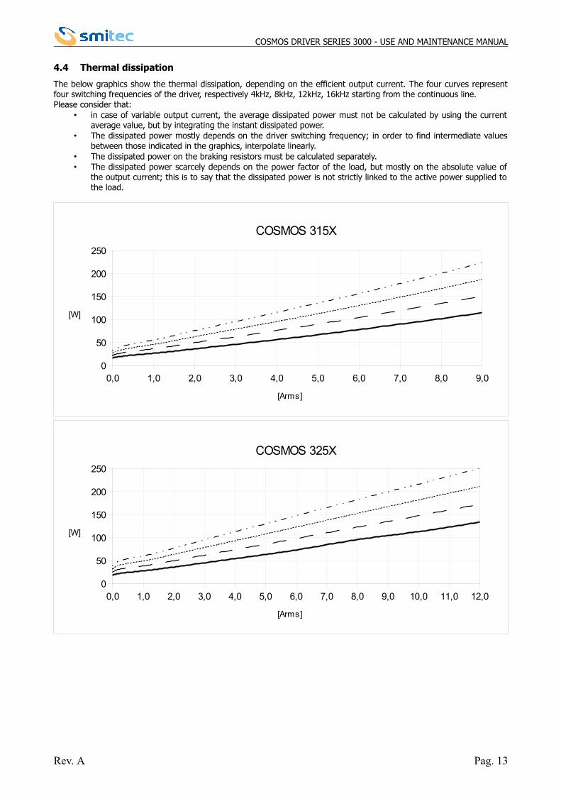
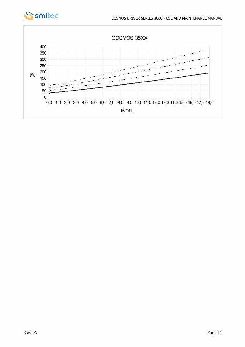
4.4 Thermal dissipation
The below graphics show the thermal dissipation, depending on the efficient output current. The four curves representfour switching frequencies of the driver, respectively 4kHz, 8kHz, 12kHz, 16kHz starting from the continuous line.Please consider that:
• in case of variable output current, the average dissipated power must not be calculated by using the currentaverage value, but by integrating the instant dissipated power.
• The dissipated power mostly depends on the driver switching frequency; in order to find intermediate valuesbetween those indicated in the graphics, interpolate linearly.
• The dissipated power on the braking resistors must be calculated separately. • The dissipated power scarcely depends on the power factor of the load, but mostly on the absolute value of
the output current; this is to say that the dissipated power is not strictly linked to the active power supplied tothe load.
Rev. A Pag. 13
0,0 1,0 2,0 3,0 4,0 5,0 6,0 7,0 8,0 9,00
50
100
150
200
250
COSMOS 315X
[Arms]
[W]
0,0 1,0 2,0 3,0 4,0 5,0 6,0 7,0 8,0 9,0 10,0 11,0 12,00
50
100
150
200
250
COSMOS 325X
[Arms]
[W]
COSMOS DRIVER SERIES 3000 - USE AND MAINTENANCE MANUAL
Rev. A Pag. 14
0,0 1,0 2,0 3,0 4,0 5,0 6,0 7,0 8,0 9,0 10,0 11,0 12,0 13,0 14,0 15,0 16,0 17,0 18,00
50
100
150
200
250
300
350
400
COSMOS 35XX
[Arms]
[W]
COSMOS DRIVER SERIES 3000 - USE AND MAINTENANCE MANUAL
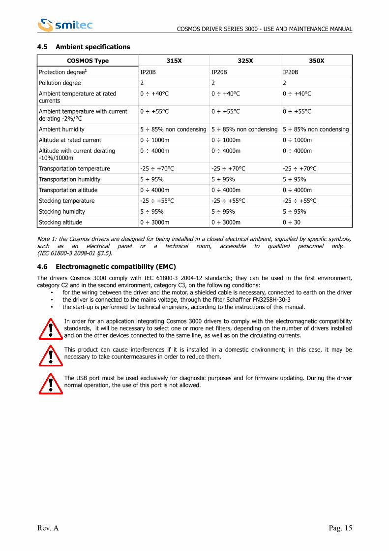
4.5 Ambient specifications
COSMOS Type 315X 325X 350X
Protection degree1 IP20B IP20B IP20B
Pollution degree 2 2 2
Ambient temperature at rated currents
0 ÷ +40°C 0 ÷ +40°C 0 ÷ +40°C
Ambient temperature with current derating -2%/°C
0 ÷ +55°C 0 ÷ +55°C 0 ÷ +55°C
Ambient humidity 5 ÷ 85% non condensing 5 ÷ 85% non condensing 5 ÷ 85% non condensing
Altitude at rated current 0 ÷ 1000m 0 ÷ 1000m 0 ÷ 1000m
Altitude with current derating -10%/1000m
0 ÷ 4000m 0 ÷ 4000m 0 ÷ 4000m
Transportation temperature -25 ÷ +70°C -25 ÷ +70°C -25 ÷ +70°C
Transportation humidity 5 ÷ 95% 5 ÷ 95% 5 ÷ 95%
Transportation altitude 0 ÷ 4000m 0 ÷ 4000m 0 ÷ 4000m
Stocking temperature -25 ÷ +55°C -25 ÷ +55°C -25 ÷ +55°C
Stocking humidity 5 ÷ 95% 5 ÷ 95% 5 ÷ 95%
Stocking altitude 0 ÷ 3000m 0 ÷ 3000m 0 ÷ 30
Note 1: the Cosmos drivers are designed for being installed in a closed electrical ambient, signalled by specific symbols,such as an electrical panel or a technical room, accessible to qualified personnel only. (IEC 61800-3 2008-01 §3.5).
4.6 Electromagnetic compatibility (EMC)
The drivers Cosmos 3000 comply with IEC 61800-3 2004-12 standards; they can be used in the first environment,category C2 and in the second environment, category C3, on the following conditions:
• for the wiring between the driver and the motor, a shielded cable is necessary, connected to earth on the driver• the driver is connected to the mains voltage, through the filter Schaffner FN3258H-30-3• the start-up is performed by technical engineers, according to the instructions of this manual.
In order for an application integrating Cosmos 3000 drivers to comply with the electromagnetic compatibilitystandards, it will be necessary to select one or more net filters, depending on the number of drivers installedand on the other devices connected to the same line, as well as on the circulating currents.
This product can cause interferences if it is installed in a domestic environment; in this case, it may benecessary to take countermeasures in order to reduce them.
The USB port must be used exclusively for diagnostic purposes and for firmware updating. During the drivernormal operation, the use of this port is not allowed.
Rev. A Pag. 15
COSMOS DRIVER SERIES 3000 - USE AND MAINTENANCE MANUAL
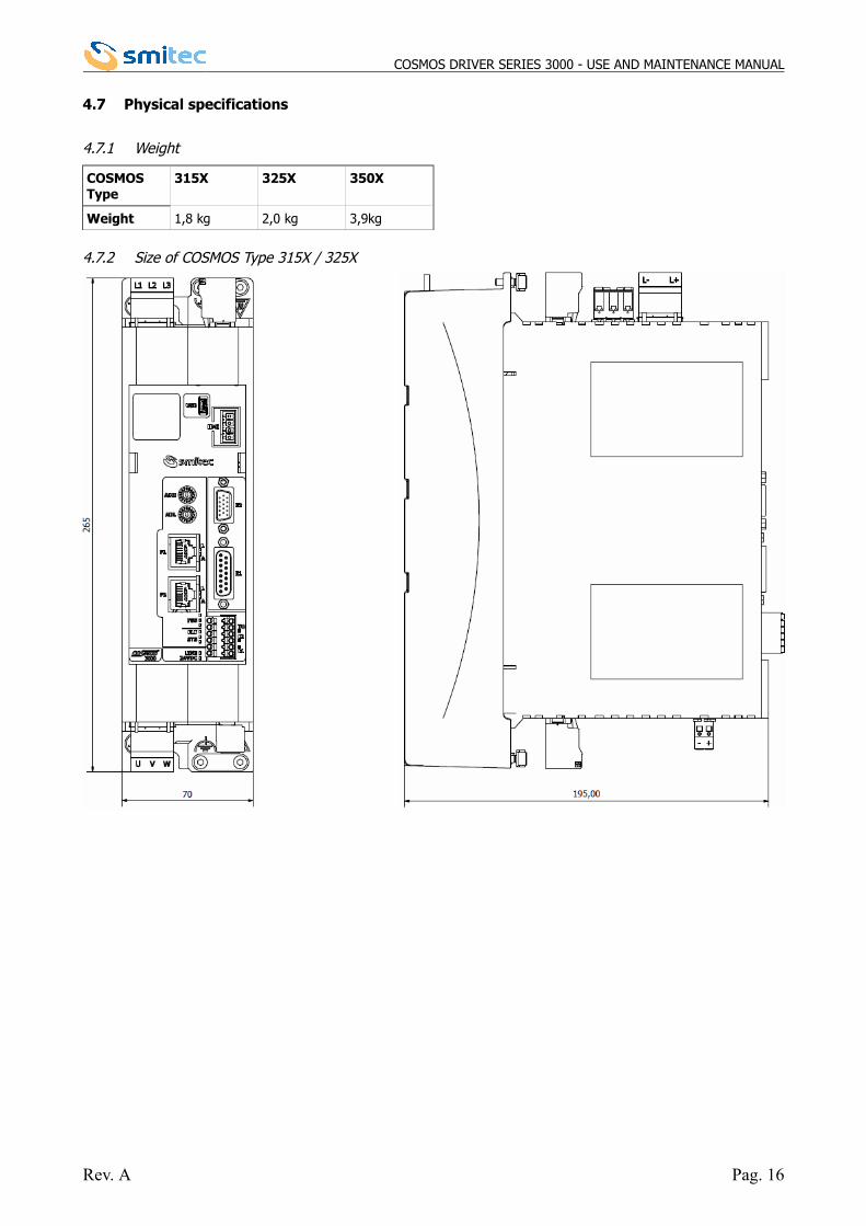
4.7 Physical specifications
4.7.1 Weight
COSMOSType
315X 325X 350X
Weight 1,8 kg 2,0 kg 3,9kg
4.7.2 Size of COSMOS Type 315X / 325X
Rev. A Pag. 16
COSMOS DRIVER SERIES 3000 - USE AND MAINTENANCE MANUAL
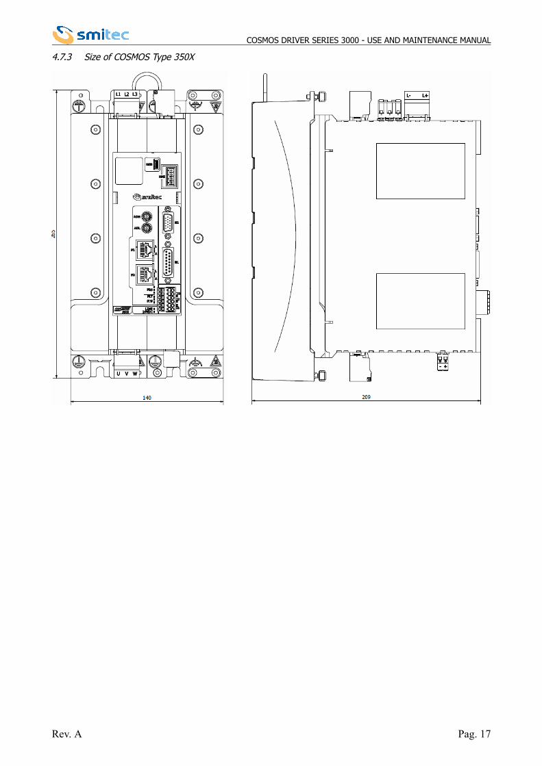
4.7.3 Size of COSMOS Type 350X
Rev. A Pag. 17
COSMOS DRIVER SERIES 3000 - USE AND MAINTENANCE MANUAL
5 INSTALLATION
5.1 Positioning and installation
The drivers COSMOS 3000 can be installed close to an iron wall connected to earth. Install the driver in vertical position,with the fan side turned downwards, so that it can be cooled also by natural convection; a space of about 10 cm mustbe left above and below the driver.In order to establish the electrical panel size, consider the thermal dissipation depending on the required output current,as indicated in chapter 4.4.
The drivers Cosmos 3000 are designed to be installed in closed electrical operating areas.
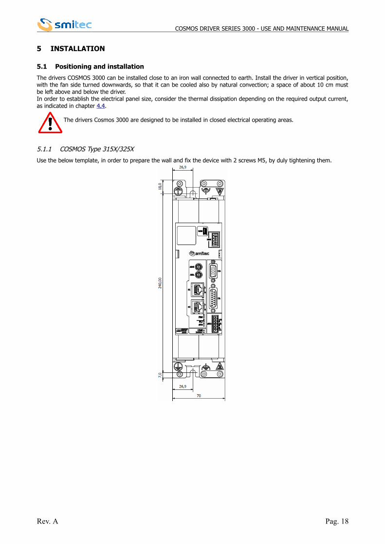
5.1.1 COSMOS Type 315X/325X
Use the below template, in order to prepare the wall and fix the device with 2 screws M5, by duly tightening them.
Rev. A Pag. 18
COSMOS DRIVER SERIES 3000 - USE AND MAINTENANCE MANUAL
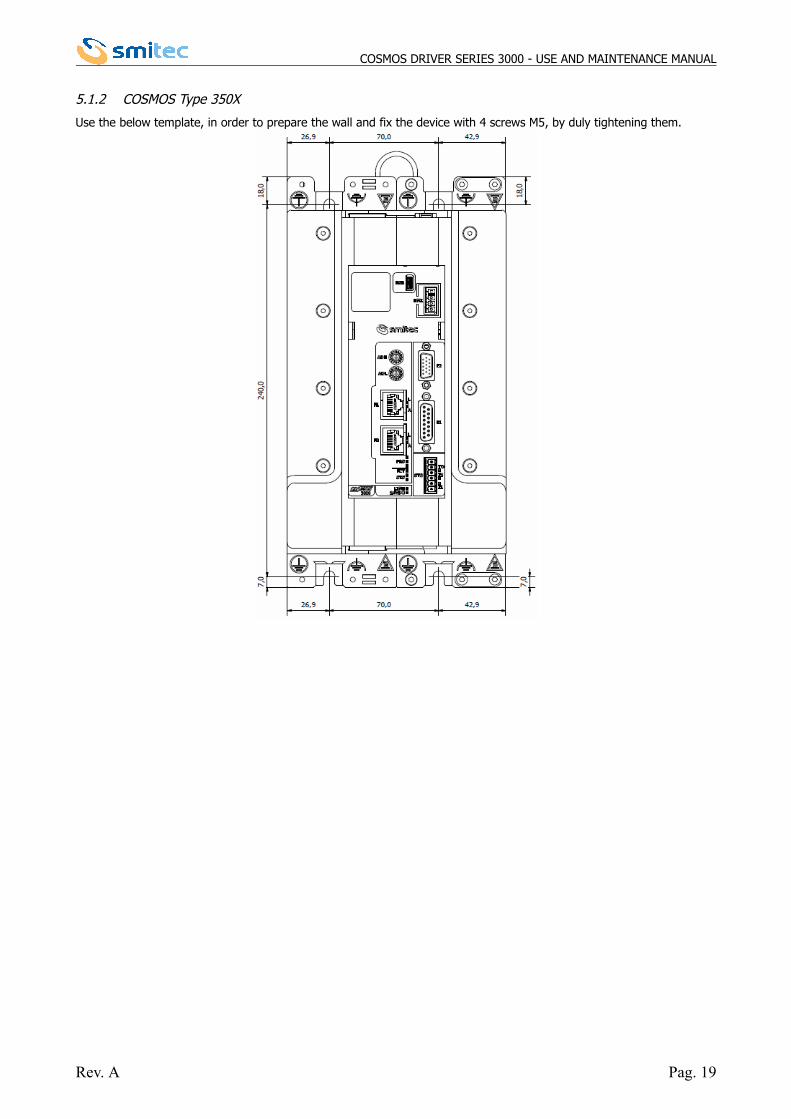
5.1.2 COSMOS Type 350X
Use the below template, in order to prepare the wall and fix the device with 4 screws M5, by duly tightening them.
Rev. A Pag. 19
COSMOS DRIVER SERIES 3000 - USE AND MAINTENANCE MANUAL
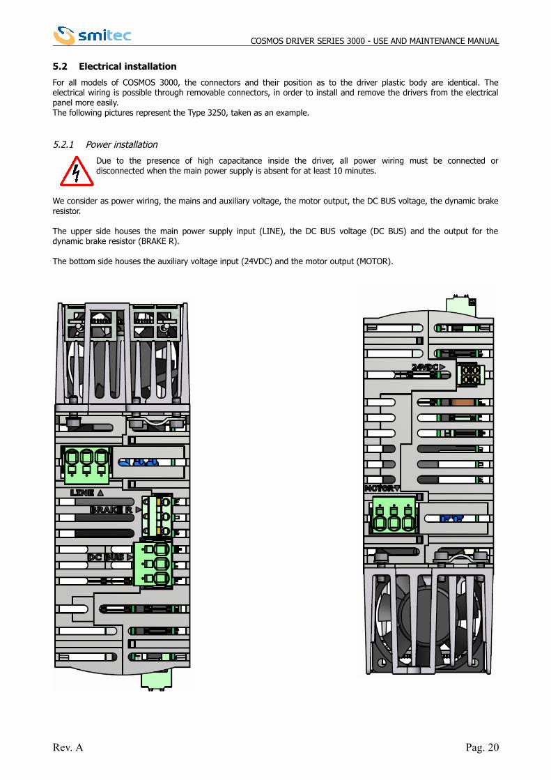
5.2 Electrical installation
For all models of COSMOS 3000, the connectors and their position as to the driver plastic body are identical. Theelectrical wiring is possible through removable connectors, in order to install and remove the drivers from the electricalpanel more easily. The following pictures represent the Type 3250, taken as an example.
5.2.1 Power installation
Due to the presence of high capacitance inside the driver, all power wiring must be connected ordisconnected when the main power supply is absent for at least 10 minutes.
We consider as power wiring, the mains and auxiliary voltage, the motor output, the DC BUS voltage, the dynamic brakeresistor.
The upper side houses the main power supply input (LINE), the DC BUS voltage (DC BUS) and the output for thedynamic brake resistor (BRAKE R).
The bottom side houses the auxiliary voltage input (24VDC) and the motor output (MOTOR).
Rev. A Pag. 20
COSMOS DRIVER SERIES 3000 - USE AND MAINTENANCE MANUAL
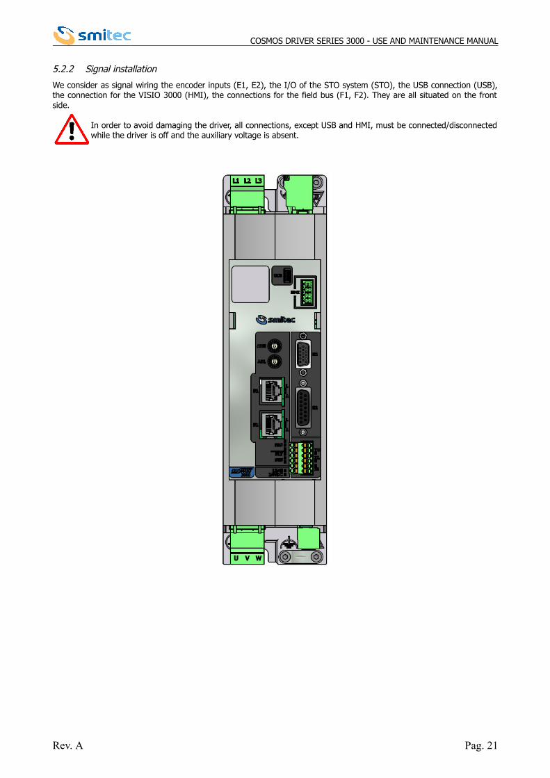
5.2.2 Signal installation
We consider as signal wiring the encoder inputs (E1, E2), the I/O of the STO system (STO), the USB connection (USB),the connection for the VISIO 3000 (HMI), the connections for the field bus (F1, F2). They are all situated on the frontside.
In order to avoid damaging the driver, all connections, except USB and HMI, must be connected/disconnectedwhile the driver is off and the auxiliary voltage is absent.
Rev. A Pag. 21
COSMOS DRIVER SERIES 3000 - USE AND MAINTENANCE MANUAL
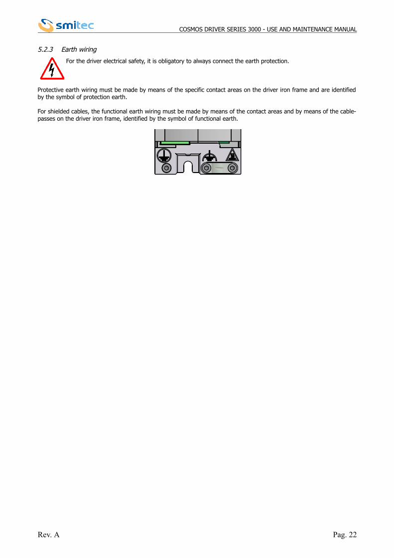
5.2.3 Earth wiring
For the driver electrical safety, it is obligatory to always connect the earth protection.
Protective earth wiring must be made by means of the specific contact areas on the driver iron frame and are identifiedby the symbol of protection earth.
For shielded cables, the functional earth wiring must be made by means of the contact areas and by means of the cable-passes on the driver iron frame, identified by the symbol of functional earth.
Rev. A Pag. 22
COSMOS DRIVER SERIES 3000 - USE AND MAINTENANCE MANUAL
5.3 Connectors wiring
Please find here below the features of the allowed cables and connectors, as well as the legend of each connection ofthe drivers COSMOS 3000.
The drivers COSMOS 3000 are electronic devices, sensitive to electrostatic charges. In order to avoid damages, it is necessary to adopt all preventive measures.
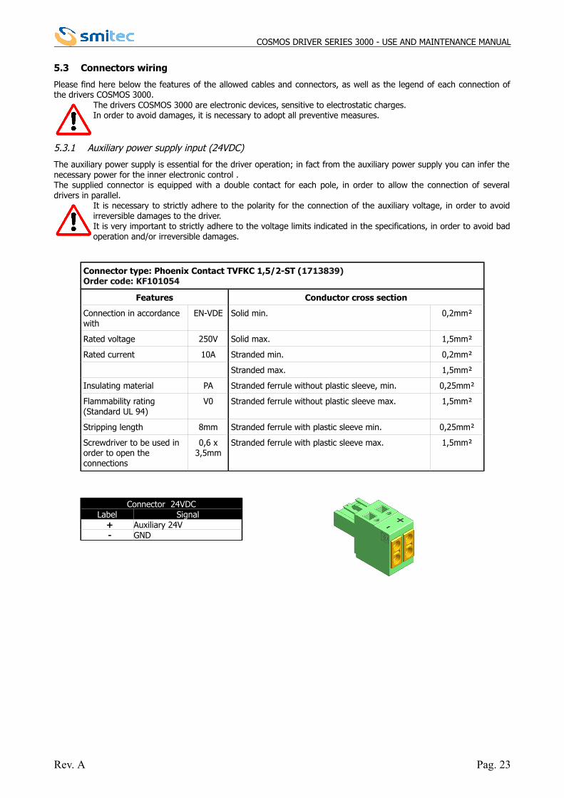
5.3.1 Auxiliary power supply input (24VDC)
The auxiliary power supply is essential for the driver operation; in fact from the auxiliary power supply you can infer thenecessary power for the inner electronic control .The supplied connector is equipped with a double contact for each pole, in order to allow the connection of severaldrivers in parallel.
It is necessary to strictly adhere to the polarity for the connection of the auxiliary voltage, in order to avoidirreversible damages to the driver. It is very important to strictly adhere to the voltage limits indicated in the specifications, in order to avoid badoperation and/or irreversible damages.
Connector type: Phoenix Contact TVFKC 1,5/2-ST (1713839)Order code: KF101054
Features Conductor cross section
Connection in accordance with
EN-VDE Solid min. 0,2mm²
Rated voltage 250V Solid max. 1,5mm²
Rated current 10A Stranded min. 0,2mm²
Stranded max. 1,5mm²
Insulating material PA Stranded ferrule without plastic sleeve, min. 0,25mm²
Flammability rating (Standard UL 94)
V0 Stranded ferrule without plastic sleeve max. 1,5mm²
Stripping length 8mm Stranded ferrule with plastic sleeve min. 0,25mm²
Screwdriver to be used in order to open the connections
0,6 x3,5mm
Stranded ferrule with plastic sleeve max. 1,5mm²
Connector 24VDCLabel Signal + Auxiliary 24V - GND
Rev. A Pag. 23
COSMOS DRIVER SERIES 3000 - USE AND MAINTENANCE MANUAL
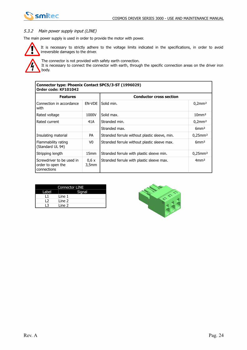
5.3.2 Main power supply input (LINE)
The main power supply is used in order to provide the motor with power.
It is necessary to strictly adhere to the voltage limits indicated in the specifications, in order to avoidirreversible damages to the driver.
The connector is not provided with safety earth connection.It is necessary to connect the connector with earth, through the specific connection areas on the driver ironbody.
Connector type: Phoenix Contact SPC5/3-ST (1996029)Order code: KF101042
Features Conductor cross section
Connection in accordance with
EN-VDE Solid min. 0,2mm²
Rated voltage 1000V Solid max. 10mm²
Rated current 41A Stranded min. 0,2mm²
Stranded max. 6mm²
Insulating material PA Stranded ferrule without plastic sleeve, min. 0,25mm²
Flammability rating (Standard UL 94)
V0 Stranded ferrule without plastic sleeve max. 6mm²
Stripping length 15mm Stranded ferrule with plastic sleeve min. 0,25mm²
Screwdriver to be used in order to open the connections
0,6 x3,5mm
Stranded ferrule with plastic sleeve max. 4mm²
Connector LINELabel Signal
L1 Line 1L2 Line 2L3 Line 2
Rev. A Pag. 24
COSMOS DRIVER SERIES 3000 - USE AND MAINTENANCE MANUAL
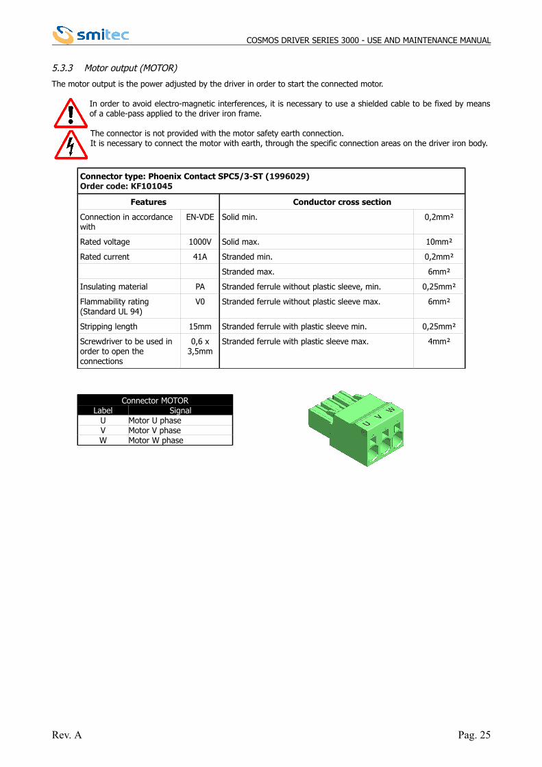
5.3.3 Motor output (MOTOR)
The motor output is the power adjusted by the driver in order to start the connected motor.
In order to avoid electro-magnetic interferences, it is necessary to use a shielded cable to be fixed by meansof a cable-pass applied to the driver iron frame.
The connector is not provided with the motor safety earth connection.It is necessary to connect the motor with earth, through the specific connection areas on the driver iron body.
Connector type: Phoenix Contact SPC5/3-ST (1996029)Order code: KF101045
Features Conductor cross section
Connection in accordance with
EN-VDE Solid min. 0,2mm²
Rated voltage 1000V Solid max. 10mm²
Rated current 41A Stranded min. 0,2mm²
Stranded max. 6mm²
Insulating material PA Stranded ferrule without plastic sleeve, min. 0,25mm²
Flammability rating (Standard UL 94)
V0 Stranded ferrule without plastic sleeve max. 6mm²
Stripping length 15mm Stranded ferrule with plastic sleeve min. 0,25mm²
Screwdriver to be used in order to open the connections
0,6 x3,5mm
Stranded ferrule with plastic sleeve max. 4mm²
Connector MOTORLabel Signal
U Motor U phaseV Motor V phaseW Motor W phase
Rev. A Pag. 25
COSMOS DRIVER SERIES 3000 - USE AND MAINTENANCE MANUAL
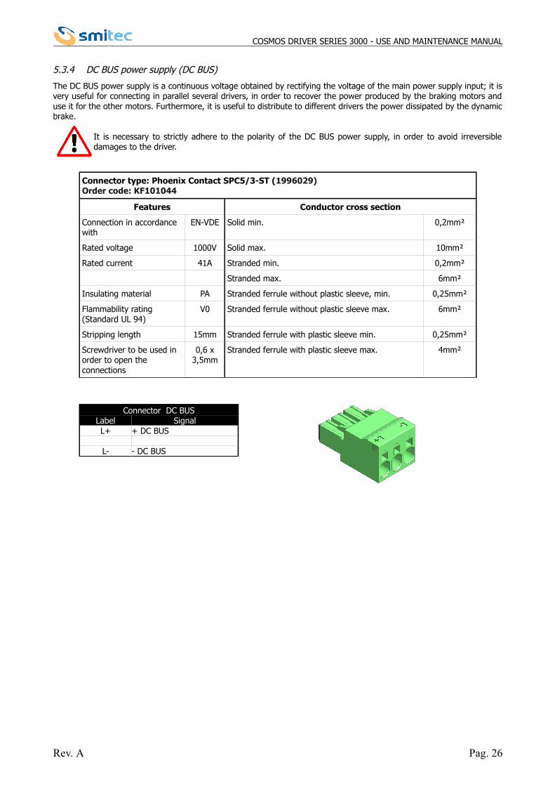
5.3.4 DC BUS power supply (DC BUS)
The DC BUS power supply is a continuous voltage obtained by rectifying the voltage of the main power supply input; it isvery useful for connecting in parallel several drivers, in order to recover the power produced by the braking motors anduse it for the other motors. Furthermore, it is useful to distribute to different drivers the power dissipated by the dynamicbrake.
It is necessary to strictly adhere to the polarity of the DC BUS power supply, in order to avoid irreversibledamages to the driver.
Connector type: Phoenix Contact SPC5/3-ST (1996029)Order code: KF101044
Features Conductor cross section
Connection in accordance with
EN-VDE Solid min. 0,2mm²
Rated voltage 1000V Solid max. 10mm²
Rated current 41A Stranded min. 0,2mm²
Stranded max. 6mm²
Insulating material PA Stranded ferrule without plastic sleeve, min. 0,25mm²
Flammability rating (Standard UL 94)
V0 Stranded ferrule without plastic sleeve max. 6mm²
Stripping length 15mm Stranded ferrule with plastic sleeve min. 0,25mm²
Screwdriver to be used in order to open the connections
0,6 x3,5mm
Stranded ferrule with plastic sleeve max. 4mm²
Connector DC BUSLabel SignalL+ + DC BUS
L- - DC BUS
Rev. A Pag. 26
COSMOS DRIVER SERIES 3000 - USE AND MAINTENANCE MANUAL
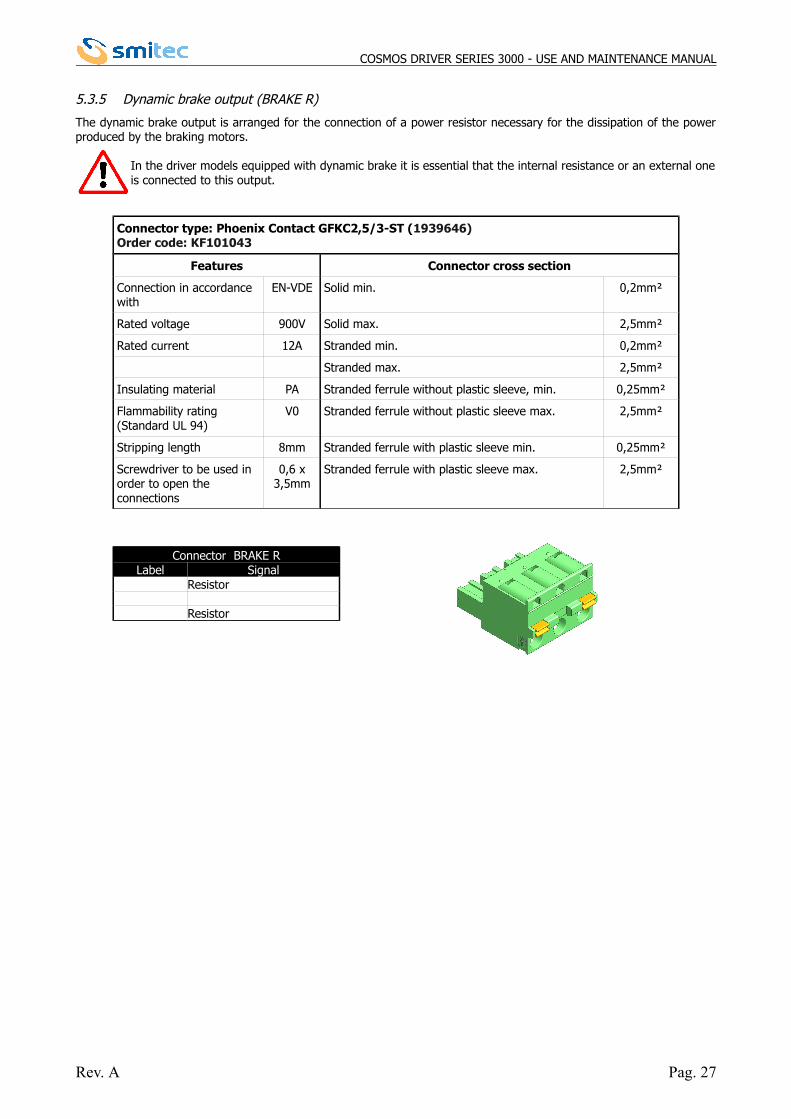
5.3.5 Dynamic brake output (BRAKE R)
The dynamic brake output is arranged for the connection of a power resistor necessary for the dissipation of the powerproduced by the braking motors.
In the driver models equipped with dynamic brake it is essential that the internal resistance or an external oneis connected to this output.
Connector type: Phoenix Contact GFKC2,5/3-ST (1939646)Order code: KF101043
Features Connector cross section
Connection in accordance with
EN-VDE Solid min. 0,2mm²
Rated voltage 900V Solid max. 2,5mm²
Rated current 12A Stranded min. 0,2mm²
Stranded max. 2,5mm²
Insulating material PA Stranded ferrule without plastic sleeve, min. 0,25mm²
Flammability rating (Standard UL 94)
V0 Stranded ferrule without plastic sleeve max. 2,5mm²
Stripping length 8mm Stranded ferrule with plastic sleeve min. 0,25mm²
Screwdriver to be used in order to open the connections
0,6 x3,5mm
Stranded ferrule with plastic sleeve max. 2,5mm²
Connector BRAKE RLabel Signal
Resistor
Resistor
Rev. A Pag. 27
COSMOS DRIVER SERIES 3000 - USE AND MAINTENANCE MANUAL
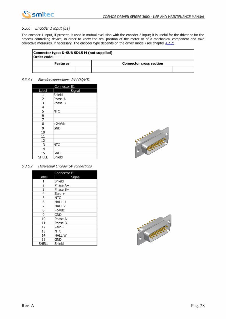
5.3.6 Encoder 1 input (E1)
The encoder 1 input, if present, is used in mutual exclusion with the encoder 2 input; it is useful for the driver or for theprocess controlling device, in order to know the real position of the motor or of a mechanical component and takecorrective measures, if necessary. The encoder type depends on the driver model (see chapter 4.2.2).
Connector type: D-SUB SD15 M (not supplied)Order code: --------
Features Connector cross section
5.3.6.1 Encoder connections 24V OC/HTL
Connector E1Label Signal
1 Shield2 Phase A3 Phase B45 NTC678 +24Vdc9 GND10111213 NTC1415 GND
SHELL Shield
5.3.6.2 Differential Encoder 5V connections
Connector E1Label Signal
1 Shield2 Phase A+3 Phase B+4 Zero +5 NTC6 HALL U7 HALL V8 +5Vdc9 GND10 Phase A-11 Phase B-12 Zero -13 NTC14 HALL W15 GND
SHELL Shield
Rev. A Pag. 28
COSMOS DRIVER SERIES 3000 - USE AND MAINTENANCE MANUAL
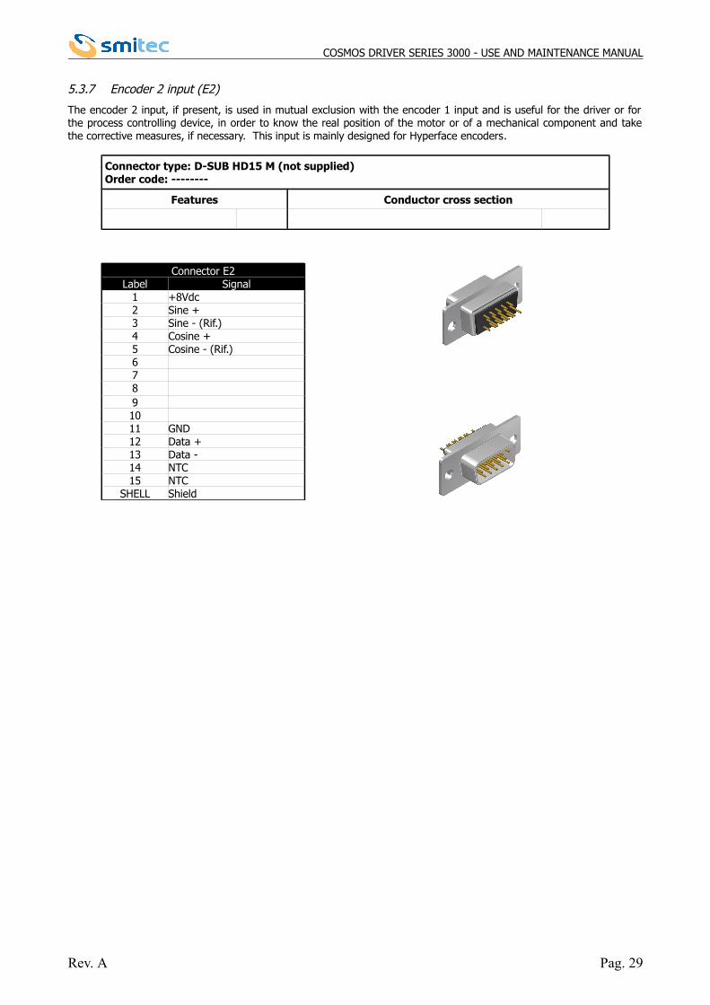
5.3.7 Encoder 2 input (E2)
The encoder 2 input, if present, is used in mutual exclusion with the encoder 1 input and is useful for the driver or forthe process controlling device, in order to know the real position of the motor or of a mechanical component and takethe corrective measures, if necessary. This input is mainly designed for Hyperface encoders.
Connector type: D-SUB HD15 M (not supplied)Order code: --------
Features Conductor cross section
Connector E2Label Signal
1 +8Vdc2 Sine +3 Sine - (Rif.)4 Cosine +5 Cosine - (Rif.)67891011 GND12 Data +13 Data -14 NTC15 NTC
SHELL Shield
Rev. A Pag. 29
COSMOS DRIVER SERIES 3000 - USE AND MAINTENANCE MANUAL
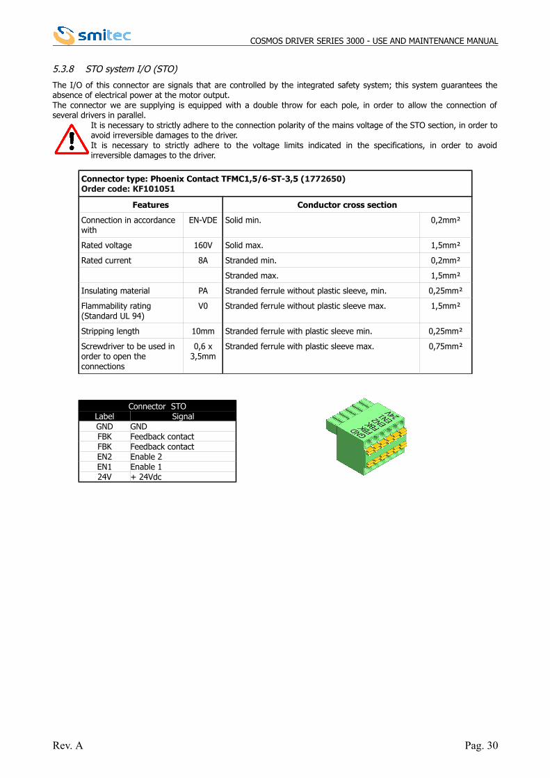
5.3.8 STO system I/O (STO)
The I/O of this connector are signals that are controlled by the integrated safety system; this system guarantees theabsence of electrical power at the motor output. The connector we are supplying is equipped with a double throw for each pole, in order to allow the connection ofseveral drivers in parallel.
It is necessary to strictly adhere to the connection polarity of the mains voltage of the STO section, in order toavoid irreversible damages to the driver. It is necessary to strictly adhere to the voltage limits indicated in the specifications, in order to avoidirreversible damages to the driver.
Connector type: Phoenix Contact TFMC1,5/6-ST-3,5 (1772650)Order code: KF101051
Features Conductor cross section
Connection in accordance with
EN-VDE Solid min. 0,2mm²
Rated voltage 160V Solid max. 1,5mm²
Rated current 8A Stranded min. 0,2mm²
Stranded max. 1,5mm²
Insulating material PA Stranded ferrule without plastic sleeve, min. 0,25mm²
Flammability rating (Standard UL 94)
V0 Stranded ferrule without plastic sleeve max. 1,5mm²
Stripping length 10mm Stranded ferrule with plastic sleeve min. 0,25mm²
Screwdriver to be used in order to open the connections
0,6 x3,5mm
Stranded ferrule with plastic sleeve max. 0,75mm²
Connector STOLabel SignalGND GNDFBK Feedback contactFBK Feedback contactEN2 Enable 2EN1 Enable 124V + 24Vdc
Rev. A Pag. 30
COSMOS DRIVER SERIES 3000 - USE AND MAINTENANCE MANUAL
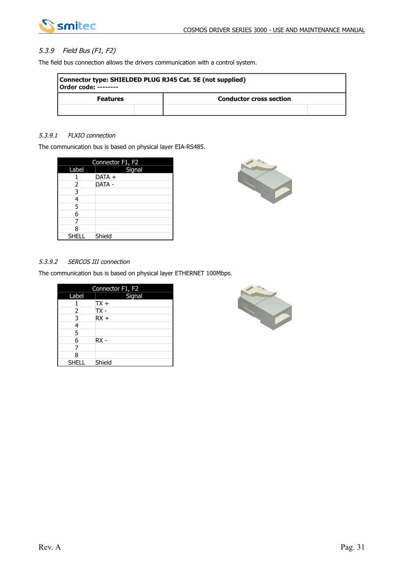
5.3.9 Field Bus (F1, F2)
The field bus connection allows the drivers communication with a control system.
Connector type: SHIELDED PLUG RJ45 Cat. 5E (not supplied)Order code: --------
Features Conductor cross section
5.3.9.1 FLXIO connection
The communication bus is based on physical layer EIA-RS485.
Connector F1, F2Label Signal
1 DATA +2 DATA -345678
SHELL Shield
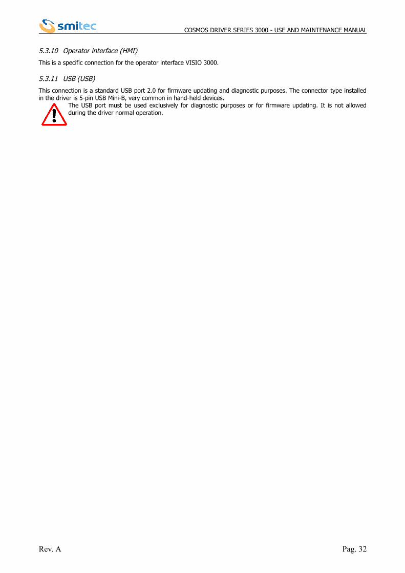
5.3.9.2 SERCOS III connection
The communication bus is based on physical layer ETHERNET 100Mbps.
Connector F1, F2Label Signal
1 TX +2 TX -3 RX +456 RX -78
SHELL Shield
Rev. A Pag. 31
COSMOS DRIVER SERIES 3000 - USE AND MAINTENANCE MANUAL
5.3.10 Operator interface (HMI)
This is a specific connection for the operator interface VISIO 3000.
5.3.11 USB (USB)
This connection is a standard USB port 2.0 for firmware updating and diagnostic purposes. The connector type installedin the driver is 5-pin USB Mini-B, very common in hand-held devices.
The USB port must be used exclusively for diagnostic purposes or for firmware updating. It is not allowedduring the driver normal operation.
Rev. A Pag. 32
COSMOS DRIVER SERIES 3000 - USE AND MAINTENANCE MANUAL
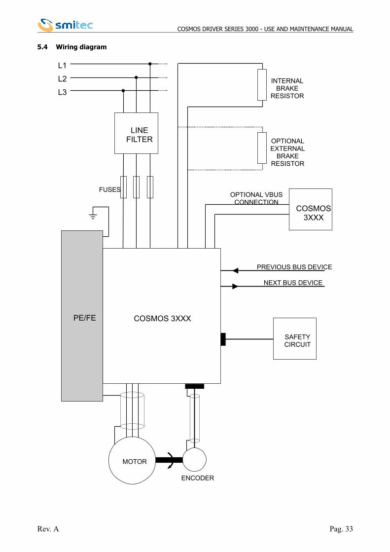
5.4 Wiring diagram
Rev. A Pag. 33
L1
L2
L3
FUSES
LINEFILTER
COSMOS 3XXX
COSMOS3XXX
OPTIONAL VBUSCONNECTION
OPTIONALEXTERNAL
BRAKERESISTOR
PREVIOUS BUS DEVICE
NEXT BUS DEVICE
MOTOR
PE/FE
ENCODER
SAFETYCIRCUIT
INTERNALBRAKE
RESISTOR
COSMOS DRIVER SERIES 3000 - USE AND MAINTENANCE MANUAL
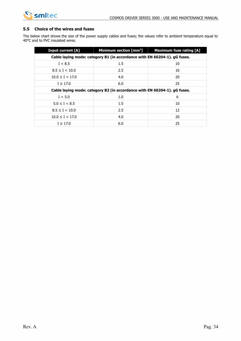
5.5 Choice of the wires and fuses
The below chart shows the size of the power supply cables and fuses; the values refer to ambient temperature equal to40°C and to PVC insulated wires.
Input current [A] Minimum section [mm2] Maximum fuse rating [A]
Cable laying mode: category B1 (in accordance with EN 60204-1). gG fuses.
I < 8.5 1.5 10
8.5 ≤ I < 10.0 2.5 16
10.0 ≤ I < 17.0 4.0 20
I ≥ 17.0 6.0 25
Cable laying mode: category B2 (in accordance with EN 60204-1). gG fuses.
I < 5.0 1.0 6
5.0 ≤ I < 8.5 1.5 10
8.5 ≤ I < 10.0 2.5 12
10.0 ≤ I < 17.0 4.0 20
I ≥ 17.0 6.0 25
Rev. A Pag. 34
COSMOS DRIVER SERIES 3000 - USE AND MAINTENANCE MANUAL
6 Safety integrated system
6.1 Description
The drivers COSMOS 3000 are equipped with a circuit for the STO function (Safe Torque Off). This function, if enabled,allows the driver output to be disabled so that the driver cannot generate torque (or force, in case of linear motors). Themotor will actually stop in a time that can vary according to the inertia or to the load mechanical features; if it werenecessary to guarantee the stop of the mechanical device within a maximum time (example a load lifted by a pulley), itwill be necessary to implement this function with additional systems.Features:
• the intervention of the STO function totally excludes the driver possibility to control the motor • there is no way to disable the safety function, either intentionally or unintentionally• the STO system is equipped with two independent inputs; a break-down of one of the two channels does not
interfere with the operation of the other channel• the two inputs are powered by the same power supply, independent from any other power supplies of the
driver• the STO system was designed to tolerate 1 hardware break-down • the level of safety integrity is SIL2 with PFH (Probability of random Failure per Hour) < 1x10⁻⁹
• The STO mission time is 20 years• The required ambient conditions, the use and maintenance are the same as those required by the driver.
In order to guarantee the required safety degree, it is necessary to adequately control the signals, for example by usinga certified safety PLC.
6.2 Operation
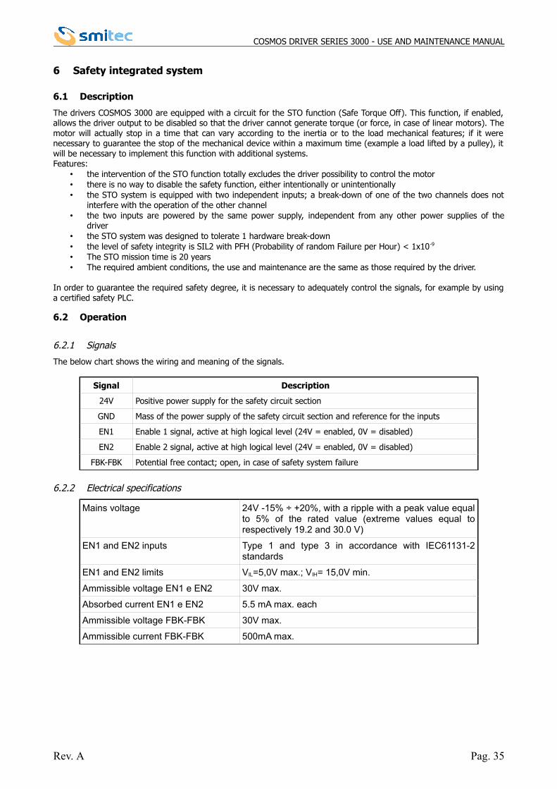
6.2.1 Signals
The below chart shows the wiring and meaning of the signals.
Signal Description
24V Positive power supply for the safety circuit section
GND Mass of the power supply of the safety circuit section and reference for the inputs
EN1 Enable 1 signal, active at high logical level (24V = enabled, 0V = disabled)
EN2 Enable 2 signal, active at high logical level (24V = enabled, 0V = disabled)
FBK-FBK Potential free contact; open, in case of safety system failure
6.2.2 Electrical specifications
Mains voltage 24V -15% ÷ +20%, with a ripple with a peak value equalto 5% of the rated value (extreme values equal torespectively 19.2 and 30.0 V)
EN1 and EN2 inputs Type 1 and type 3 in accordance with IEC61131-2standards
EN1 and EN2 limits VIL=5,0V max.; VIH= 15,0V min.
Ammissible voltage EN1 e EN2 30V max.
Absorbed current EN1 e EN2 5.5 mA max. each
Ammissible voltage FBK-FBK 30V max.
Ammissible current FBK-FBK 500mA max.
Rev. A Pag. 35
COSMOS DRIVER SERIES 3000 - USE AND MAINTENANCE MANUAL
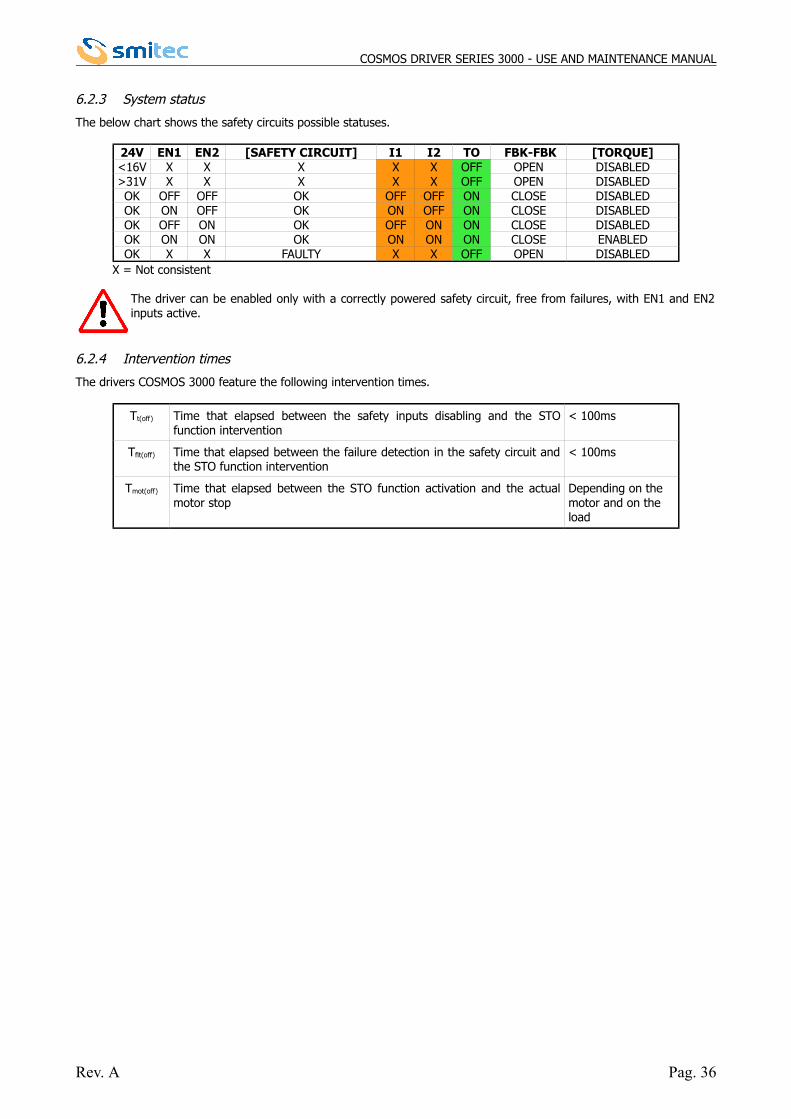
6.2.3 System status
The below chart shows the safety circuits possible statuses.
24V EN1 EN2 [SAFETY CIRCUIT] I1 I2 TO FBK-FBK [TORQUE]<16V X X X X X OFF OPEN DISABLED>31V X X X X X OFF OPEN DISABLEDOK OFF OFF OK OFF OFF ON CLOSE DISABLEDOK ON OFF OK ON OFF ON CLOSE DISABLEDOK OFF ON OK OFF ON ON CLOSE DISABLEDOK ON ON OK ON ON ON CLOSE ENABLEDOK X X FAULTY X X OFF OPEN DISABLED
X = Not consistent
The driver can be enabled only with a correctly powered safety circuit, free from failures, with EN1 and EN2inputs active.
6.2.4 Intervention times
The drivers COSMOS 3000 feature the following intervention times.
Tt(off) Time that elapsed between the safety inputs disabling and the STOfunction intervention
< 100ms
Tflt(off) Time that elapsed between the failure detection in the safety circuit andthe STO function intervention
< 100ms
Tmot(off) Time that elapsed between the STO function activation and the actualmotor stop
Depending on the motor and on the load
Rev. A Pag. 36
COSMOS DRIVER SERIES 3000 - USE AND MAINTENANCE MANUAL
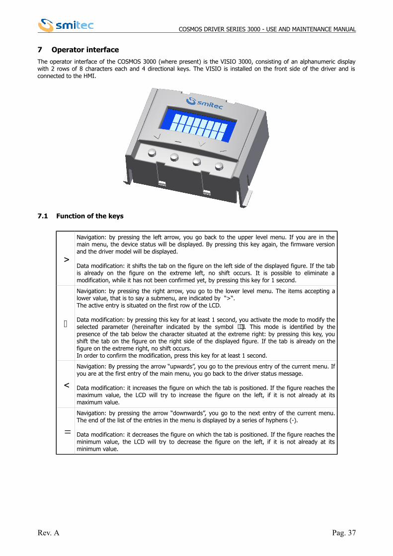
7 Operator interface
The operator interface of the COSMOS 3000 (where present) is the VISIO 3000, consisting of an alphanumeric displaywith 2 rows of 8 characters each and 4 directional keys. The VISIO is installed on the front side of the driver and isconnected to the HMI.
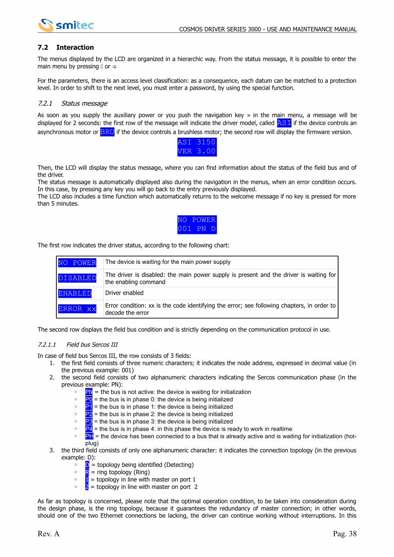
7.1 Function of the keys
Navigation: by pressing the left arrow, you go back to the upper level menu. If you are in themain menu, the device status will be displayed. By pressing this key again, the firmware versionand the driver model will be displayed.
Data modification: it shifts the tab on the figure on the left side of the displayed figure. If the tabis already on the figure on the extreme left, no shift occurs. It is possible to eliminate amodification, while it has not been confirmed yet, by pressing this key for 1 second.
Navigation: by pressing the right arrow, you go to the lower level menu. The items accepting alower value, that is to say a submenu, are indicated by “>“.The active entry is situated on the first row of the LCD.
Data modification: by pressing this key for at least 1 second, you activate the mode to modify theselected parameter (hereinafter indicated by the symbol ). This mode is identified by thepresence of the tab below the character situated at the extreme right: by pressing this key, youshift the tab on the figure on the right side of the displayed figure. If the tab is already on thefigure on the extreme right, no shift occurs.In order to confirm the modification, press this key for at least 1 second.
Navigation: By pressing the arrow “upwards”, you go to the previous entry of the current menu. Ifyou are at the first entry of the main menu, you go back to the driver status message.
Data modification: it increases the figure on which the tab is positioned. If the figure reaches themaximum value, the LCD will try to increase the figure on the left, if it is not already at itsmaximum value.
Navigation: by pressing the arrow “downwards”, you go to the next entry of the current menu.The end of the list of the entries in the menu is displayed by a series of hyphens (-).
Data modification: it decreases the figure on which the tab is positioned. If the figure reaches theminimum value, the LCD will try to decrease the figure on the left, if it is not already at itsminimum value.
Rev. A Pag. 37
COSMOS DRIVER SERIES 3000 - USE AND MAINTENANCE MANUAL
7.2 Interaction
The menus displayed by the LCD are organized in a hierarchic way. From the status message, it is possible to enter themain menu by pressing or .
For the parameters, there is an access level classification: as a consequence, each datum can be matched to a protectionlevel. In order to shift to the next level, you must enter a password, by using the special function.
7.2.1 Status message
As soon as you supply the auxiliary power or you push the navigation key in the main menu, a message will bedisplayed for 2 seconds: the first row of the message will indicate the driver model, called ASI if the device controls an
asynchronous motor or BRU if the device controls a brushless motor; the second row will display the firmware version.
Then, the LCD will display the status message, where you can find information about the status of the field bus and ofthe driver. The status message is automatically displayed also during the navigation in the menus, when an error condition occurs.In this case, by pressing any key you will go back to the entry previously displayed. The LCD also includes a time function which automatically returns to the welcome message if no key is pressed for morethan 5 minutes.
The first row indicates the driver status, according to the following chart:
NO POWER The device is waiting for the main power supply
DISABLED The driver is disabled: the main power supply is present and the driver is waiting forthe enabling command
ENABLED Driver enabled
ERROR xx Error condition: xx is the code identifying the error; see following chapters, in order todecode the error
The second row displays the field bus condition and is strictly depending on the communication protocol in use.
7.2.1.1 Field bus Sercos III
In case of field bus Sercos III, the row consists of 3 fields:1. the first field consists of three numeric characters; it indicates the node address, expressed in decimal value (in
the previous example: 001)2. the second field consists of two alphanumeric characters indicating the Sercos communication phase (in the
previous example: PN):◦ PN = the bus is not active: the device is waiting for initialization◦ P0 = the bus is in phase 0: the device is being initialized◦ P1 = the bus is in phase 1: the device is being initialized◦ P2 = the bus is in phase 2: the device is being initialized◦ P3 = the bus is in phase 3: the device is being initialized◦ P4 = the bus is in phase 4: in this phase the device is ready to work in realtime◦ PH = the device has been connected to a bus that is already active and is waiting for initialization (hot-
plug)3. the third field consists of only one alphanumeric character: it indicates the connection topology (in the previous
example: D):◦ D = topology being identified (Detecting)◦ R = ring topology (Ring)◦ 1 = topology in line with master on port 1◦ 2 = topology in line with master on port 2
As far as topology is concerned, please note that the optimal operation condition, to be taken into consideration duringthe design phase, is the ring topology, because it guarantees the redundancy of master connection; in other words,should one of the two Ethernet connections be lacking, the driver can continue working without interruptions. In this
Rev. A Pag. 38
NO POWER001 PN D
ASI 3150VER 3.00
COSMOS DRIVER SERIES 3000 - USE AND MAINTENANCE MANUAL
case, the displayed topology will change from R to 1 or 2, depending on the port from where the driver receives the datafrom the master.If you select the topology in line, the driver will display 1 or 2, depending on the port from where the driver receives thedata from the master.
7.2.1.2 Field bus FlxIO
NO COMM The field bus is not active and the device is not in service mode
XXX.X Hz The device is generating the frequency XXX.X; the field bus is active or in service mode
7.2.2 Access level
By selecting the item LEVEL in the main menu and by pressing the key , you enter the function to insert thepassword, in order to modify the parameter access level.
By means of the arrows, it is possible to enter the password, by confirming it by pressing the key .If the password is correct, the LCD will display a message of successful result and will display a new access level.
By pressing any key, the LCD will return to the main menu.Here are the passwords available for the user:
Level Password1 -2 PROGR3 TARAT4 >Reserved to SMITEC<
If no key is pressed for 5 minutes, the system will return to level 1 and it will not be possible to modify the data anylonger, unless you enter the password of the next level.
7.2.3 Main menu
The following chart shows the menu hierarchy, the entries displayed, the minimum level necessary for the modificationand the description.
Menu Entry Lev. Description
1>PARAM - This section lists all entries that enable you to set the
driver parameters and displays the size unitsmeasured by the driver.
2 LEVEL - Modification of the access level
Rev. A Pag. 39
LEVEL[1]PW XXXXX
LEVEL[3]PW RIGHT
COSMOS DRIVER SERIES 3000 - USE AND MAINTENANCE MANUAL
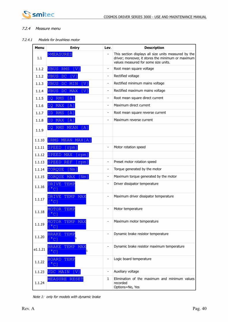
7.2.4 Measure menu
7.2.4.1 Models for brushless motor
Menu Entry Lev. Description
1.1>MEASURES - This section displays all size units measured by the
driver; moreover, it stores the minimum or maximumvalues measured for some size units.
1.1.2 VBUS RMS [V] - Root mean square voltage
1.1.2 VBUS DC [V] - Rectified voltage
1.1.3 VBUS DC MIN [V] - Rectified minimum mains voltage
1.1.4 VBUS DC MAX [V] - Rectified maximum mains voltage
1.1.5 IQ RMS [A] - Root mean square direct current
1.1.6 IQ MAX [A] - Maximum direct current
1.1.7 ID RMS [A] - Root mean square reverse current
1.1.8 ID MAX [A] - Maximum reverse current
1.1.9IQ RMS MEAN [A]
1.1.10 IRMS MEAN MAX[A]
1.1.11 SPEED [rpm] - Motor rotation speed
1.1.12 SPEED MAX [rpm]
1.1.13 SPEED REF [rpm] - Preset motor rotation speed
1.1.14 TORQUE [Nm] - Torque generated by the motor
1.1.15 TORQUE MAX [Nm] - Maximum torque generated by the motor
1.1.16DRIVE TEMP[°C]
- Driver dissipator temperature
1.1.17DRIVE TEMP MAX[°C]
- Maximum driver dissipator temperature
1.1.18MOTOR TEMP[°C]
- Motor temperature
1.1.19MOTOR TEMP MAX[°C]
- Maximum motor temperature
1.1.20BRAKE TEMP[°C] 1
- Dynamic brake resistor temperature
e1.1.21BRAKE TEMP MAX[°C] 1
- Dynamic brake resistor maximum temperature
1.1.22BOARD TEMP[°C]
- Logic board temperature
1.1.23 VDC MAIN [V] - Auxiliary voltage
1.1.24MEASURE RESET 1 Elimination of the maximum and minimum values
recordedOptions=No, Yes
Note 1: only for models with dynamic brake
Rev. A Pag. 40
COSMOS DRIVER SERIES 3000 - USE AND MAINTENANCE MANUAL
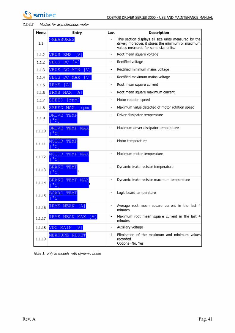
7.2.4.2 Models for asynchronous motor
Menu Entry Lev. Description
1.1>MEASURES - This section displays all size units measured by the
driver; moreover, it stores the minimum or maximumvalues measured for some size units.
1.1.2 VBUS RMS [V] - Root mean square voltage
1.1.2 VBUS DC [V] - Rectified voltage
1.1.3 VBUS DC MIN [V] - Rectified minimum mains voltage
1.1.4 VBUS DC MAX [V] - Rectified maximum mains voltage
1.1.5 IRMS [A] - Root mean square current
1.1.6 IRMS MAX [A] - Root mean square maximum current
1.1.7 SPEED [rpm] - Motor rotation speed
1.1.8 SPEED MAX [rpm] - Maximum value detected of motor rotation speed
1.1.9DRIVE TEMP[°C]
- Driver dissipator temperature
1.1.10DRIVE TEMP MAX[°C]
- Maximum driver dissipator temperature
1.1.11MOTOR TEMP[°C]
- Motor temperature
1.1.12MOTOR TEMP MAX[°C]
- Maximum motor temperature
1.1.13BRAKE TEMP[°C] 1
- Dynamic brake resistor temperature
1.1.14BRAKE TEMP MAX[°C] 1
- Dynamic brake resistor maximum temperature
1.1.15BOARD TEMP[°C]
- Logic board temperature
1.1.16 IRMS MEAN [A] - Average root mean square current in the last 4minutes
1.1.17 IRMS MEAN MAX [A] - Maximum root mean square current in the last 4minutes
1.1.18 VDC MAIN [V] - Auxiliary voltage
1.1.19MEASURE RESET 1 Elimination of the maximum and minimum values
recordedOptions=No, Yes
Note 1: only in models with dynamic brake
Rev. A Pag. 41
COSMOS DRIVER SERIES 3000 - USE AND MAINTENANCE MANUAL
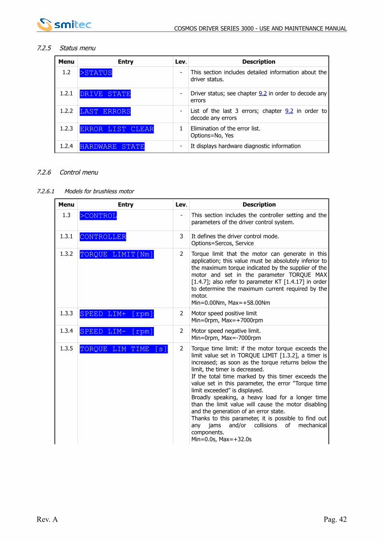
7.2.5 Status menu
Menu Entry Lev. Description
1.2 >STATUS - This section includes detailed information about thedriver status.
1.2.1 DRIVE STATE - Driver status; see chapter 9.2 in order to decode anyerrors
1.2.2 LAST ERRORS - List of the last 3 errors; chapter 9.2 in order todecode any errors
1.2.3 ERROR LIST CLEAR 1 Elimination of the error list.Options=No, Yes
1.2.4 HARDWARE STATE - It displays hardware diagnostic information
7.2.6 Control menu
7.2.6.1 Models for brushless motor
Menu Entry Lev. Description
1.3 >CONTROL - This section includes the controller setting and theparameters of the driver control system.
1.3.1 CONTROLLER 3 It defines the driver control mode.Options=Sercos, Service
1.3.2 TORQUE LIMIT[Nm] 2 Torque limit that the motor can generate in thisapplication; this value must be absolutely inferior tothe maximum torque indicated by the supplier of themotor and set in the parameter TORQUE MAX[1.4.7]; also refer to parameter KT [1.4.17] in orderto determine the maximum current required by themotor.Min=0.00Nm, Max=+58.00Nm
1.3.3 SPEED LIM+ [rpm] 2 Motor speed positive limitMin=0rpm, Max=+7000rpm
1.3.4 SPEED LIM- [rpm] 2 Motor speed negative limit.Min=0rpm, Max=-7000rpm
1.3.5 TORQUE LIM TIME [s] 2 Torque time limit: if the motor torque exceeds thelimit value set in TORQUE LIMIT [1.3.2], a timer isincreased; as soon as the torque returns below thelimit, the timer is decreased.If the total time marked by this timer exceeds thevalue set in this parameter, the error “Torque timelimit exceeded” is displayed. Broadly speaking, a heavy load for a longer timethan the limit value will cause the motor disablingand the generation of an error state. Thanks to this parameter, it is possible to find outany jams and/or collisions of mechanicalcomponents.Min=0.0s, Max=+32.0s
Rev. A Pag. 42
COSMOS DRIVER SERIES 3000 - USE AND MAINTENANCE MANUAL
1.3.6 KPV [A/rpm] 2 Speed proportional gain.The driver continuously detects the rotor speed andcompares it to the reference speed rate. Thedifference between the two values is multiplied bythe proportional gain, in order to determine theproportional current. This value of the current is summed up to thecurrent due to the integrative gain. These twovalues determine the motor current. The higher the difference of speed is, the more thecurrent in the motor is. Through this process, if it iscontinuous, the motor tends to assume thereference speed, even when the load conditionsapplied to the motor change. The proportional gain must be usually determinedfor each specific case, according to the motorapplication. This value is strongly influenced by theinertial mass applied to the motor shaft. The morethe mass is, the lower the gain will be. In the practical tests, it is necessary to find out thegain empirically, by progressively increasing thevalue, until the motor begins to be unsteady,depending on the motor noise and vibrations. Onceyou reached the limit, decrease the gain by 10–20%, as a safety margin.Larger size motors usually show higher values thansmaller size motors. Min=0.000A/rpm, Max=+3.430A/rpm
1.3.7 KIV [A/G] 2 Speed integrative gain. The angular difference between the reference andthe rotor is integrated and multiplied by this factor,in order to determine the integrative current. Thiscurrent value is summed up to the current due tothe proportional gain. They altogether determine themotor current.If you integrate the angular speed within the time,you will obtain an angle; as a consequence, it ispossible to express this factor in Ampere per degree;in fact, if you set a speed rate of 1000 rpm and youset this value at 1, the current in the motor willincrease by 1 ampere when the rotor slows downand loses 1 degree. Thanks to this datum, it is possible to adjust therotor speed in a very precise way, with consequentgreat advantages, especially for the applicationsrequiring high stability while running. Please note that this value is directly proportional tothe proportional gain; therefore, it is not possible toset an integrative gain without a proportional gain. This parameter has one negative effect on themotion, especially at low speed rates: hunting. It isnecessary to find the correct value of integrativegain, after determining the proportional gain, byprogressively increasing it until the hunting begins.Once you reached the limit, decrease the gain valueby 10–20%, as a safety margin, as you did for theproportional gain. Min=0.0A/Gr, Max=+540.4A/Gr
Rev. A Pag. 43
COSMOS DRIVER SERIES 3000 - USE AND MAINTENANCE MANUAL
1.3.8 KPP [rpm/G] 2 Position proportional gain.The driver continuously detects the rotor positionand compares it to the reference position. Thedifference between the two values is multiplied bythe proportional gain, in order to determine theproportional speed. The higher the position difference is, the higher thespeed rate applied to the motor will be. Through thisprocess, if it is continuous, the motor tends toassume the reference position, even when the loadconditions applied to the motor change. The proportional gain must be usually determinedfor each specific case, according to the motorapplication. This value is strongly influenced by theinertial mass applied to the motor shaft. The morethe mass is, the lower the gain will be. In the practical tests, it is necessary to find out thegain empirically, by progressively increasing thevalue, until the motor begins to be unsteady,depending on the motor noise and vibrations. Onceyou reached the limit, decrease the gain by 10–20%, as a safety margin.Min=0.0rpm/Gr, Max=+2500.4rpm/Gr
1.3.9 KDP [] 2 Reserved.
1.3.10 VRMS NOMINAL[V] 3 Driver rated voltage.This value indicates the driver power supply.If the rated voltage of the selected motor is notincluded in the value range set for the driver, theerror “Motor voltage different from driver voltage”will be displayed.Min=0V, Max=+1000V
1.3.11 USE EXT BRAKE 3 Use of the external brake resistance.It enables you to determine whether to use theinternal resistance or the external one. Options=No, Yes
1.3.12 CHECK 3PH LINE 3 It enables the control of absence of one or morephases of input line voltage. Options=No, Yes
1.3.13 PWM FREQ [KHz] 3 It sets the switching frequency of the motor output;the higher the frequency is, the more the energylosses are, causing the motor heating; the higherthe frequency is, the lower is the noise generated bythe switching. Options=4, 8, 12, 16 kHz
1.3.14 CONTROL MODE - It displays whether the control is in position, inspeed or in torque.
Rev. A Pag. 44
COSMOS DRIVER SERIES 3000 - USE AND MAINTENANCE MANUAL
7.2.6.2 Modells for asynchronous motor
Menu Entry Lev. Description
1.3 >CONTROL - This section includes the controller setting and theparameters of the driver control system.
1.3.1 CONTROLLER 3 It determines the driver control mode.Options=FLXIO, Service
1.3.2 ACC RAMP [Hz/s] 2 Frequency ramps acceleration value
1.3.3 DEC RAMP [Hz/s] 2 Frequency ramps deceleration value
1.3.4 FREQ MIN [Hz]
2 Minimum frequency that can be generated by thedriver, expressed in hertz.Together with the value VRMS MIN, it determinesone of the points defining the line V/f thatdetermines the voltage generated depending on therequired frequency.
1.3.5 FREQ NOM [Hz]
2 Rated frequency in hertz.Together with the value VRMS NOM, it determinesone of the points defining the line V/f thatdetermines the voltage generated depending on therequired frequency.
1.3.6 FREQ MAX [Hz]
2 Maximum frequency that can be generated by thedriver, expressed in hertz.By setting higher references, the driver generatesthis frequency.
1.3.7 VRMS MIV[V]
2 rms voltage, expressed in volt, at minimumfrequency. Together with the value FREQ MIN, itdetermines one of the points defining the line V/fthat determines the voltage generated depending onthe required frequency.
1.3.8 VRMS NOM[V]
2 Rms voltage, expressed in volt, at rated frequency.Together with the value FREQ NOM, it determinesone of the points defining the line V/f thatdetermines the voltage generated depending on therequired frequency.
Rev. A Pag. 45
COSMOS DRIVER SERIES 3000 - USE AND MAINTENANCE MANUAL
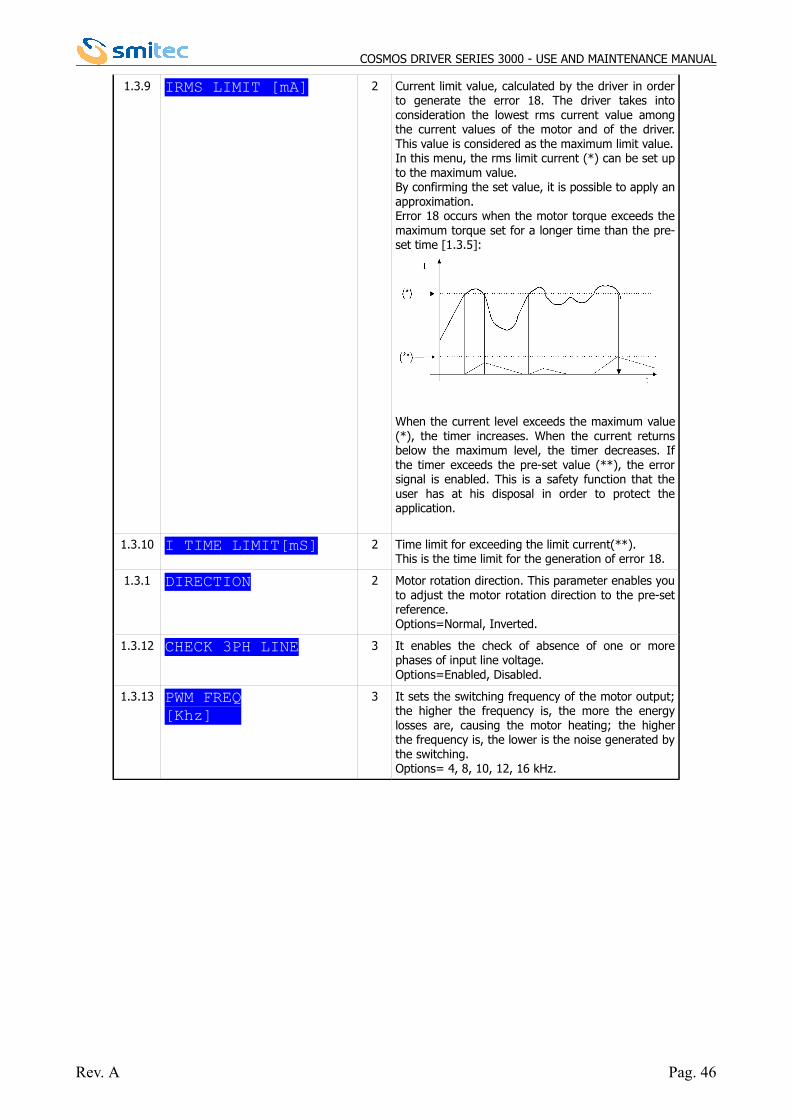
1.3.9 IRMS LIMIT [mA] 2 Current limit value, calculated by the driver in orderto generate the error 18. The driver takes intoconsideration the lowest rms current value amongthe current values of the motor and of the driver.This value is considered as the maximum limit value.In this menu, the rms limit current (*) can be set upto the maximum value.By confirming the set value, it is possible to apply anapproximation. Error 18 occurs when the motor torque exceeds themaximum torque set for a longer time than the pre-set time [1.3.5]:
When the current level exceeds the maximum value(*), the timer increases. When the current returnsbelow the maximum level, the timer decreases. Ifthe timer exceeds the pre-set value (**), the errorsignal is enabled. This is a safety function that theuser has at his disposal in order to protect theapplication.
1.3.10 I TIME LIMIT[mS] 2 Time limit for exceeding the limit current(**).This is the time limit for the generation of error 18.
1.3.1 DIRECTION 2 Motor rotation direction. This parameter enables youto adjust the motor rotation direction to the pre-setreference. Options=Normal, Inverted.
1.3.12 CHECK 3PH LINE 3 It enables the check of absence of one or morephases of input line voltage.Options=Enabled, Disabled.
1.3.13 PWM FREQ[Khz]
3 It sets the switching frequency of the motor output;the higher the frequency is, the more the energylosses are, causing the motor heating; the higherthe frequency is, the lower is the noise generated bythe switching. Options= 4, 8, 10, 12, 16 kHz.
Rev. A Pag. 46
COSMOS DRIVER SERIES 3000 - USE AND MAINTENANCE MANUAL
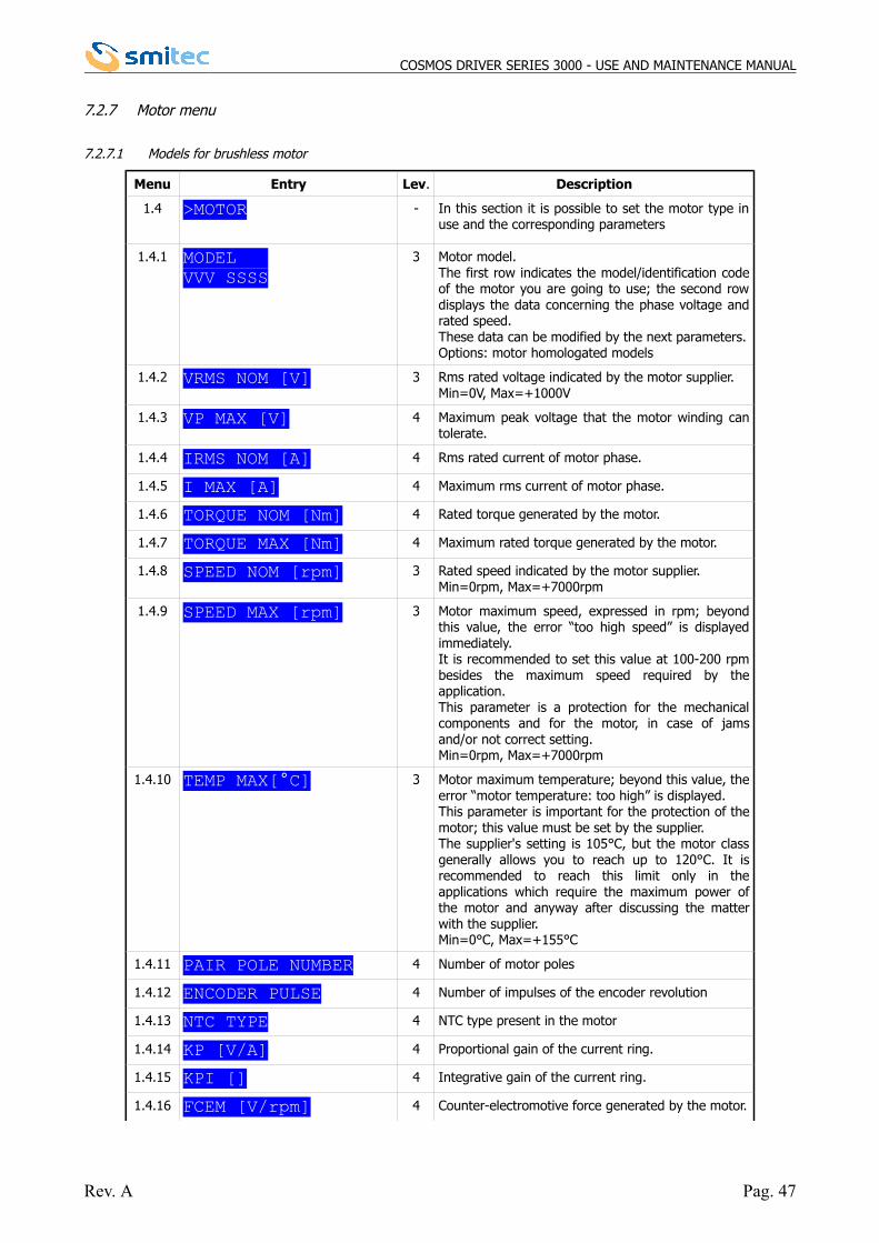
7.2.7 Motor menu
7.2.7.1 Models for brushless motor
Menu Entry Lev. Description
1.4 >MOTOR - In this section it is possible to set the motor type inuse and the corresponding parameters
1.4.1 MODEL VVV SSSS
3 Motor model.The first row indicates the model/identification codeof the motor you are going to use; the second rowdisplays the data concerning the phase voltage andrated speed.These data can be modified by the next parameters.Options: motor homologated models
1.4.2 VRMS NOM [V] 3 Rms rated voltage indicated by the motor supplier.Min=0V, Max=+1000V
1.4.3 VP MAX [V] 4 Maximum peak voltage that the motor winding cantolerate.
1.4.4 IRMS NOM [A] 4 Rms rated current of motor phase.
1.4.5 I MAX [A] 4 Maximum rms current of motor phase.
1.4.6 TORQUE NOM [Nm] 4 Rated torque generated by the motor.
1.4.7 TORQUE MAX [Nm] 4 Maximum rated torque generated by the motor.
1.4.8 SPEED NOM [rpm] 3 Rated speed indicated by the motor supplier.Min=0rpm, Max=+7000rpm
1.4.9 SPEED MAX [rpm] 3 Motor maximum speed, expressed in rpm; beyondthis value, the error “too high speed” is displayedimmediately. It is recommended to set this value at 100-200 rpmbesides the maximum speed required by theapplication.This parameter is a protection for the mechanicalcomponents and for the motor, in case of jamsand/or not correct setting.Min=0rpm, Max=+7000rpm
1.4.10 TEMP MAX[°C] 3 Motor maximum temperature; beyond this value, theerror “motor temperature: too high” is displayed.This parameter is important for the protection of themotor; this value must be set by the supplier. The supplier's setting is 105°C, but the motor classgenerally allows you to reach up to 120°C. It isrecommended to reach this limit only in theapplications which require the maximum power ofthe motor and anyway after discussing the matterwith the supplier. Min=0°C, Max=+155°C
1.4.11 PAIR POLE NUMBER 4 Number of motor poles
1.4.12 ENCODER PULSE 4 Number of impulses of the encoder revolution
1.4.13 NTC TYPE 4 NTC type present in the motor
1.4.14 KP [V/A] 4 Proportional gain of the current ring.
1.4.15 KPI [] 4 Integrative gain of the current ring.
1.4.16 FCEM [V/rpm] 4 Counter-electromotive force generated by the motor.
Rev. A Pag. 47
COSMOS DRIVER SERIES 3000 - USE AND MAINTENANCE MANUAL
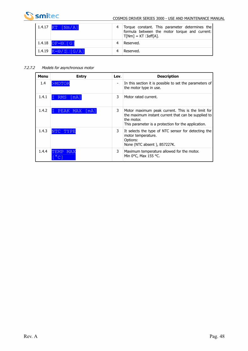
1.4.17 KT [Nm/A] 4 Torque constant. This parameter determines theformula between the motor torque and current:T[Nm] = KT ⋅ Ieff[A].
1.4.18 OF-Ɵ[G] 4 Reserved.
1.4.19 K-Ɵ/I[G/A] 4 Reserved.
7.2.7.2 Models for asynchronous motor
Menu Entry Lev. Description
1.4 >MOTOR - In this section it is possible to set the parameters ofthe motor type in use.
1.4.1 I RMS [mA] 3 Motor rated current.
1.4.2 I PEAK MAX [mA] 3 Motor maximum peak current. This is the limit forthe maximum instant current that can be supplied tothe motor.This parameter is a protection for the application.
1.4.3 NTC TYPE 3 It selects the type of NTC sensor for detecting themotor temperature.Options:None (NTC absent ), B57227K.
1.4.4 TEMP MAX[°C]
3 Maximum temperature allowed for the motor.Min 0°C, Max 155 °C.
Rev. A Pag. 48
COSMOS DRIVER SERIES 3000 - USE AND MAINTENANCE MANUAL
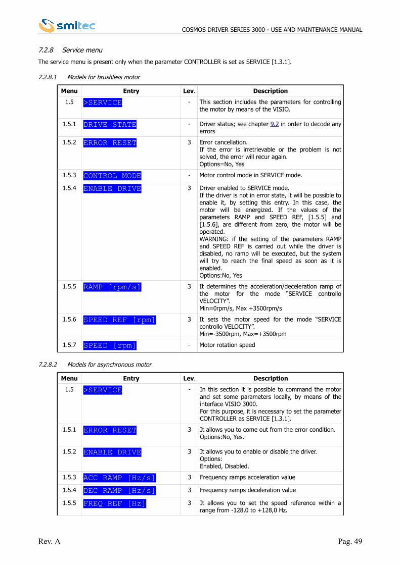
7.2.8 Service menu
The service menu is present only when the parameter CONTROLLER is set as SERVICE [1.3.1].
7.2.8.1 Models for brushless motor
Menu Entry Lev. Description
1.5 >SERVICE - This section includes the parameters for controllingthe motor by means of the VISIO.
1.5.1 DRIVE STATE - Driver status; see chapter 9.2 in order to decode anyerrors
1.5.2 ERROR RESET 3 Error cancellation.If the error is irretrievable or the problem is notsolved, the error will recur again. Options=No, Yes
1.5.3 CONTROL MODE - Motor control mode in SERVICE mode.
1.5.4 ENABLE DRIVE 3 Driver enabled to SERVICE mode.If the driver is not in error state, it will be possible toenable it, by setting this entry. In this case, themotor will be energized. If the values of theparameters RAMP and SPEED REF, [1.5.5] and[1.5.6], are different from zero, the motor will beoperated.WARNING: if the setting of the parameters RAMPand SPEED REF is carried out while the driver isdisabled, no ramp will be executed, but the systemwill try to reach the final speed as soon as it isenabled. Options:No, Yes
1.5.5 RAMP [rpm/s] 3 It determines the acceleration/deceleration ramp ofthe motor for the mode “SERVICE controlloVELOCITY”.Min=0rpm/s, Max +3500rpm/s
1.5.6 SPEED REF [rpm] 3 It sets the motor speed for the mode “SERVICEcontrollo VELOCITY”.Min=-3500rpm, Max=+3500rpm
1.5.7 SPEED [rpm] - Motor rotation speed
7.2.8.2 Models for asynchronous motor
Menu Entry Lev. Description
1.5 >SERVICE - In this section it is possible to command the motorand set some parameters locally, by means of theinterface VISIO 3000.For this purpose, it is necessary to set the parameterCONTROLLER as SERVICE [1.3.1].
1.5.1 ERROR RESET 3 It allows you to come out from the error condition.Options:No, Yes.
1.5.2 ENABLE DRIVE 3 It allows you to enable or disable the driver.Options:Enabled, Disabled.
1.5.3 ACC RAMP [Hz/s] 3 Frequency ramps acceleration value
1.5.4 DEC RAMP [Hz/s] 3 Frequency ramps deceleration value
1.5.5 FREQ REF [Hz] 3 It allows you to set the speed reference within arange from -128,0 to +128,0 Hz.
Rev. A Pag. 49
COSMOS DRIVER SERIES 3000 - USE AND MAINTENANCE MANUAL
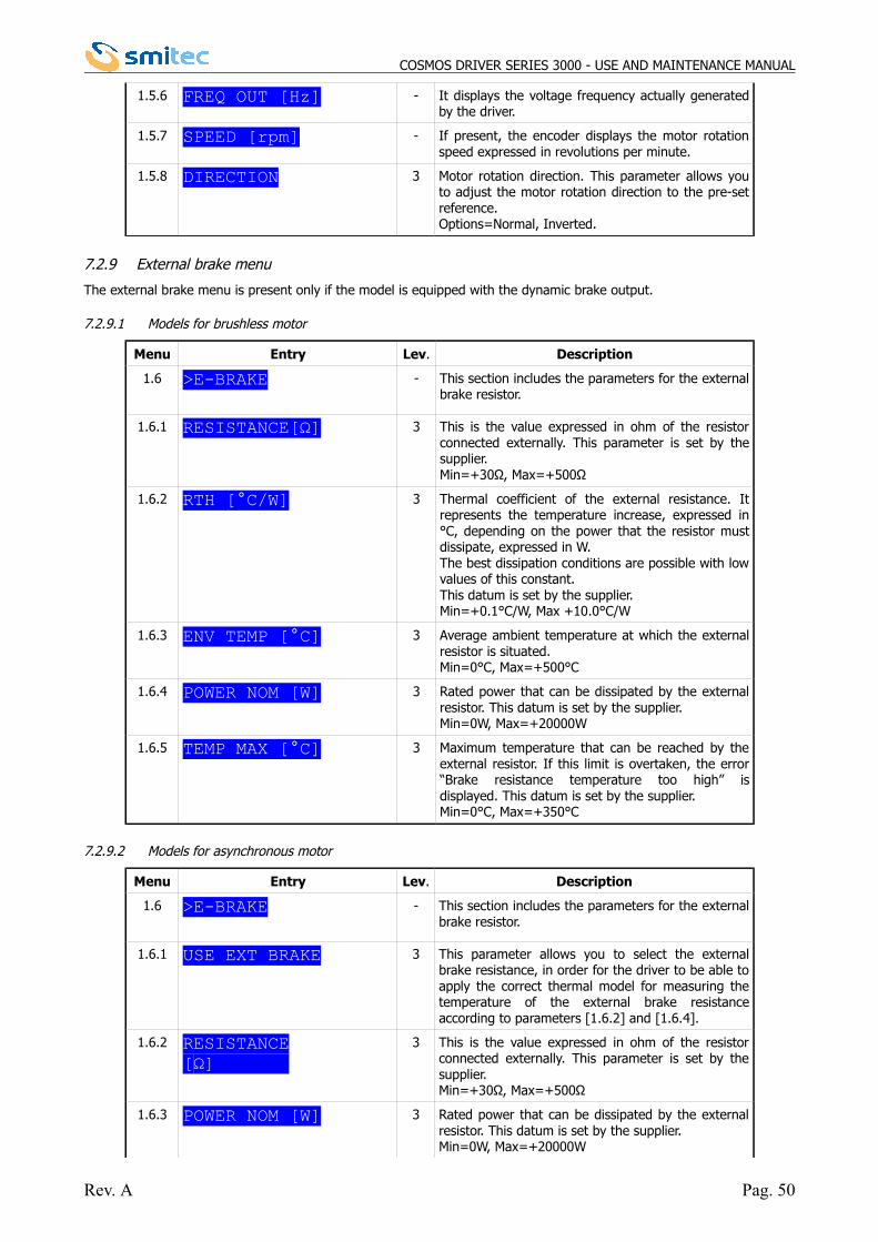
1.5.6 FREQ OUT [Hz] - It displays the voltage frequency actually generatedby the driver.
1.5.7 SPEED [rpm] - If present, the encoder displays the motor rotationspeed expressed in revolutions per minute.
1.5.8 DIRECTION 3 Motor rotation direction. This parameter allows youto adjust the motor rotation direction to the pre-setreference.Options=Normal, Inverted.
7.2.9 External brake menu
The external brake menu is present only if the model is equipped with the dynamic brake output.
7.2.9.1 Models for brushless motor
Menu Entry Lev. Description
1.6 >E-BRAKE - This section includes the parameters for the externalbrake resistor.
1.6.1 RESISTANCE[Ω] 3 This is the value expressed in ohm of the resistorconnected externally. This parameter is set by thesupplier.Min=+30Ω, Max=+500Ω
1.6.2 RTH [°C/W] 3 Thermal coefficient of the external resistance. Itrepresents the temperature increase, expressed in°C, depending on the power that the resistor mustdissipate, expressed in W. The best dissipation conditions are possible with lowvalues of this constant.This datum is set by the supplier.Min=+0.1°C/W, Max +10.0°C/W
1.6.3 ENV TEMP [°C] 3 Average ambient temperature at which the externalresistor is situated.Min=0°C, Max=+500°C
1.6.4 POWER NOM [W] 3 Rated power that can be dissipated by the externalresistor. This datum is set by the supplier.Min=0W, Max=+20000W
1.6.5 TEMP MAX [°C] 3 Maximum temperature that can be reached by theexternal resistor. If this limit is overtaken, the error“Brake resistance temperature too high” isdisplayed. This datum is set by the supplier.Min=0°C, Max=+350°C
7.2.9.2 Models for asynchronous motor
Menu Entry Lev. Description
1.6 >E-BRAKE - This section includes the parameters for the externalbrake resistor.
1.6.1 USE EXT BRAKE 3 This parameter allows you to select the externalbrake resistance, in order for the driver to be able toapply the correct thermal model for measuring thetemperature of the external brake resistanceaccording to parameters [1.6.2] and [1.6.4].
1.6.2 RESISTANCE[Ω]
3 This is the value expressed in ohm of the resistorconnected externally. This parameter is set by thesupplier.Min=+30Ω, Max=+500Ω
1.6.3 POWER NOM [W] 3 Rated power that can be dissipated by the externalresistor. This datum is set by the supplier.Min=0W, Max=+20000W
Rev. A Pag. 50
COSMOS DRIVER SERIES 3000 - USE AND MAINTENANCE MANUAL
1.6.4 RTH [°C/W] 3 Thermal coefficient of the external resistance. Itrepresents the temperature increase, expressed in°C, depending on the power that the resistor mustdissipate, expressed in W. The best dissipation conditions are possible with lowvalues of this constant.This datum is set by the supplier.Min=+0.1°C/W, Max +10.0°C/W
1.6.5 MAX TEMP[°C]
3 Maximum temperature that can be reached by theexternal resistor. If this limit is overtaken, the error“Brake resistance temperature too high” is displayed.This datum is set by the supplier.Min=0°C, Max=+350°C
1.6.6 ENV TEMP[°C]
3 Average ambient temperature at which the externalresistor is situated.Min=0°C, Max=+150°C
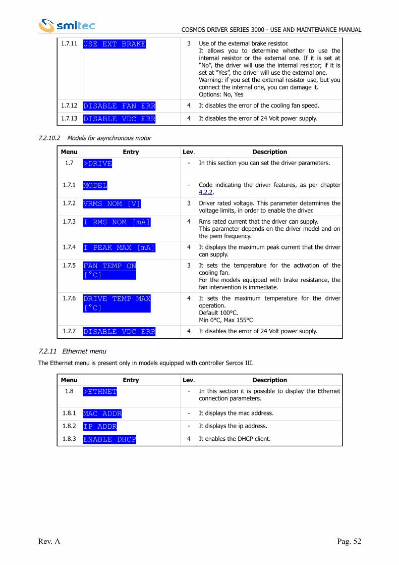
7.2.10 Driver menu
7.2.10.1 Models for brushless motor
Menu Entry Lev. Description
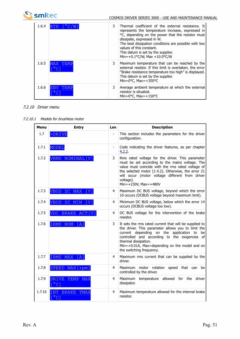
1.7 >DRIVE - This section includes the parameters for the driverconfiguration.
1.7.1 MODEL - Code indicating the driver features, as per chapter4.2.2.
1.7.2 VRMS NOMINAL[V] 3 Rms rated voltage for the driver. This parametermust be set according to the mains voltage. Thevalue must coincide with the rms rated voltage ofthe selected motor [1.4.2]. Otherwise, the error 21will occur (motor voltage different from drivervoltage).Min=+230V, Max=+480V
1.7.3 VBUS DC MAX [V] 4 Maximum DC BUS voltage, beyond which the error10 occurs (DCBUS voltage beyond maximum limit).
1.7.4 VBUS DC MIN [V] 4 Minimum DC BUS voltage, below which the error 14occurs (DCBUS voltage too low).
1.7.5 VDC BRAKE ACT[V] 4 DC BUS voltage for the intervention of the brakeresistor.
1.7.6 IRMS NOM [A] 3 It sets the rms rated current that will be supplied tothe driver. This parameter allows you to limit thecurrent depending on the application to becontrolled and according to the exigencies ofthermal dissipation.Min=+0.01A, Max=depending on the model and onthe switching frequency.
1.7.7 IRMS MAX [A] 4 Maximum rms current that can be supplied by thedriver.
1.7.8 SPEED MAX[rpm] 4 Maximum motor rotation speed that can becontrolled by the driver.
1.7.9 DRIVE TEMP MAX[°C]
4 Maximum temperature allowed for the driverdissipator.
1.7.10 INT BRAKE TMAX[°C]
4 Maximum temperature allowed for the internal brakeresistor.
Rev. A Pag. 51
COSMOS DRIVER SERIES 3000 - USE AND MAINTENANCE MANUAL
1.7.11 USE EXT BRAKE 3 Use of the external brake resistor.It allows you to determine whether to use theinternal resistor or the external one. If it is set at“No”, the driver will use the internal resistor; if it isset at “Yes”, the driver will use the external one.Warning: if you set the external resistor use, but youconnect the internal one, you can damage it. Options: No, Yes
1.7.12 DISABLE FAN ERR 4 It disables the error of the cooling fan speed.
1.7.13 DISABLE VDC ERR 4 It disables the error of 24 Volt power supply.
7.2.10.2 Models for asynchronous motor
Menu Entry Lev. Description
1.7 >DRIVE - In this section you can set the driver parameters.
1.7.1 MODEL - Code indicating the driver features, as per chapter4.2.2.
1.7.2 VRMS NOM [V] 3 Driver rated voltage. This parameter determines thevoltage limits, in order to enable the driver.
1.7.3 I RMS NOM [mA] 4 Rms rated current that the driver can supply.This parameter depends on the driver model and onthe pwm frequency.
1.7.4 I PEAK MAX [mA] 4 It displays the maximum peak current that the drivercan supply.
1.7.5 FAN TEMP ON[°C]
3 It sets the temperature for the activation of thecooling fan.For the models equipped with brake resistance, thefan intervention is immediate.
1.7.6 DRIVE TEMP MAX[°C]
4 It sets the maximum temperature for the driveroperation.Default 100°C.Min 0°C, Max 155°C
1.7.7 DISABLE VDC ERR 4 It disables the error of 24 Volt power supply.
7.2.11 Ethernet menu
The Ethernet menu is present only in models equipped with controller Sercos III.
Menu Entry Lev. Description
1.8 >ETHNET - In this section it is possible to display the Ethernetconnection parameters.
1.8.1 MAC ADDR - It displays the mac address.
1.8.2 IP ADDR - It displays the ip address.
1.8.3 ENABLE DHCP 4 It enables the DHCP client.
Rev. A Pag. 52
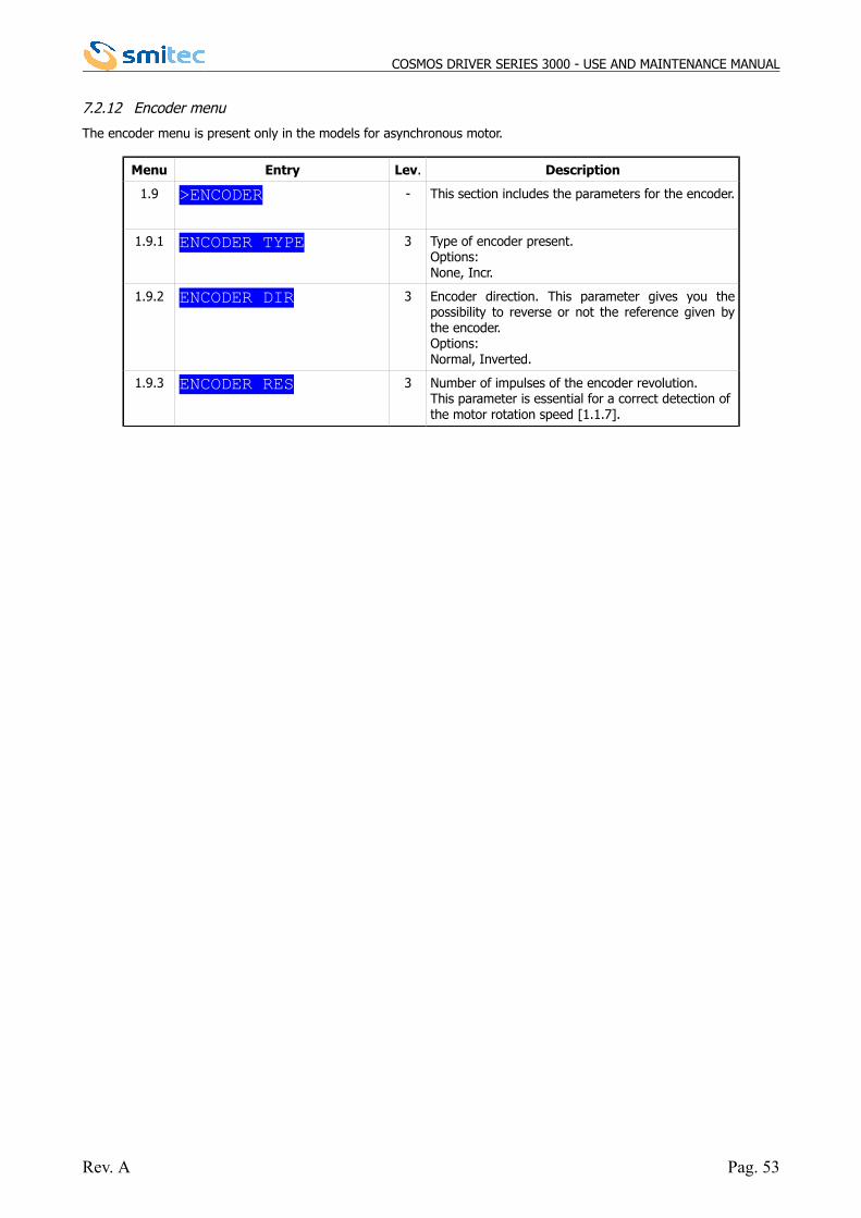
COSMOS DRIVER SERIES 3000 - USE AND MAINTENANCE MANUAL
7.2.12 Encoder menu
The encoder menu is present only in the models for asynchronous motor.
Menu Entry Lev. Description
1.9 >ENCODER - This section includes the parameters for the encoder.
1.9.1 ENCODER TYPE 3 Type of encoder present.Options:None, Incr.
1.9.2 ENCODER DIR 3 Encoder direction. This parameter gives you thepossibility to reverse or not the reference given bythe encoder.Options:Normal, Inverted.
1.9.3 ENCODER RES 3 Number of impulses of the encoder revolution.This parameter is essential for a correct detection of the motor rotation speed [1.1.7].
Rev. A Pag. 53
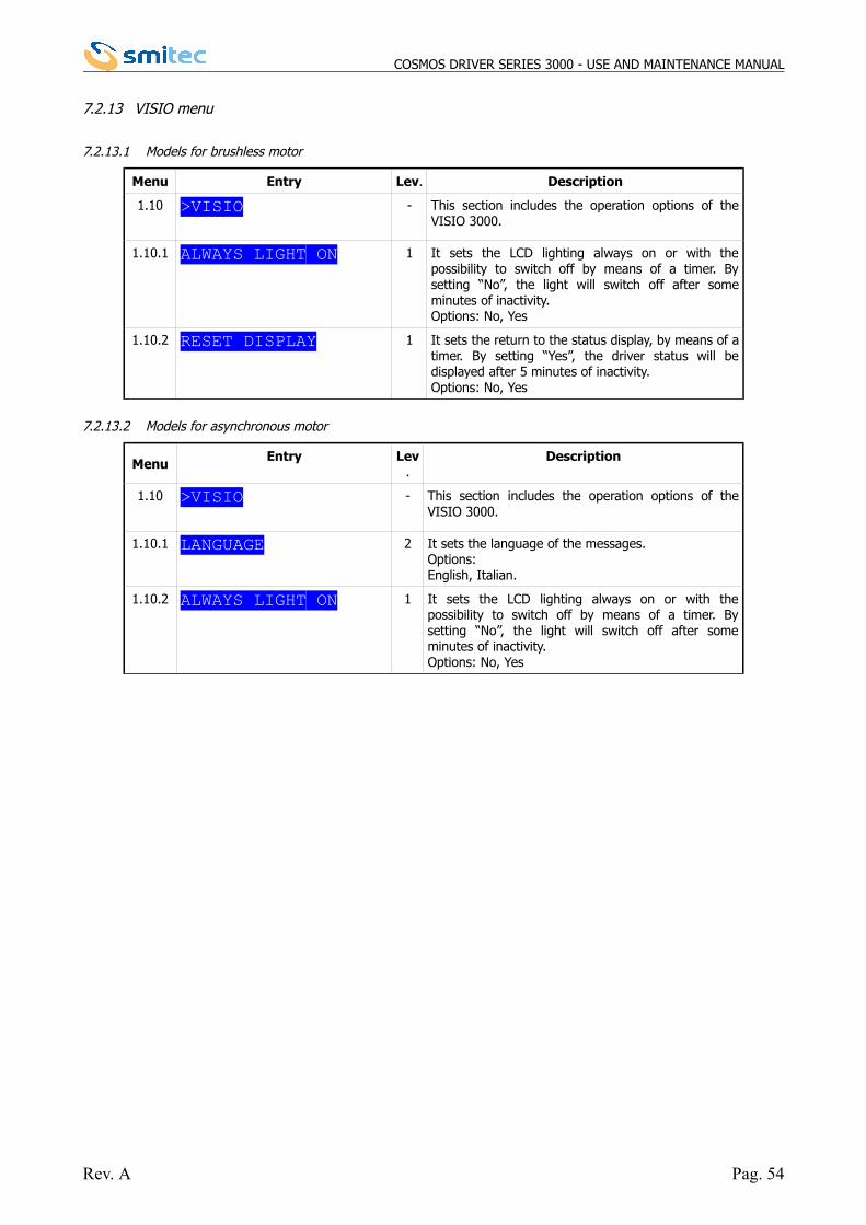
COSMOS DRIVER SERIES 3000 - USE AND MAINTENANCE MANUAL
7.2.13 VISIO menu
7.2.13.1 Models for brushless motor
Menu Entry Lev. Description
1.10 >VISIO - This section includes the operation options of theVISIO 3000.
1.10.1 ALWAYS LIGHT ON 1 It sets the LCD lighting always on or with thepossibility to switch off by means of a timer. Bysetting “No”, the light will switch off after someminutes of inactivity. Options: No, Yes
1.10.2 RESET DISPLAY 1 It sets the return to the status display, by means of atimer. By setting “Yes”, the driver status will bedisplayed after 5 minutes of inactivity.Options: No, Yes
7.2.13.2 Models for asynchronous motor
Menu Entry Lev.
Description
1.10 >VISIO - This section includes the operation options of theVISIO 3000.
1.10.1 LANGUAGE 2 It sets the language of the messages.Options:English, Italian.
1.10.2 ALWAYS LIGHT ON 1 It sets the LCD lighting always on or with thepossibility to switch off by means of a timer. Bysetting “No”, the light will switch off after someminutes of inactivity.Options: No, Yes
Rev. A Pag. 54
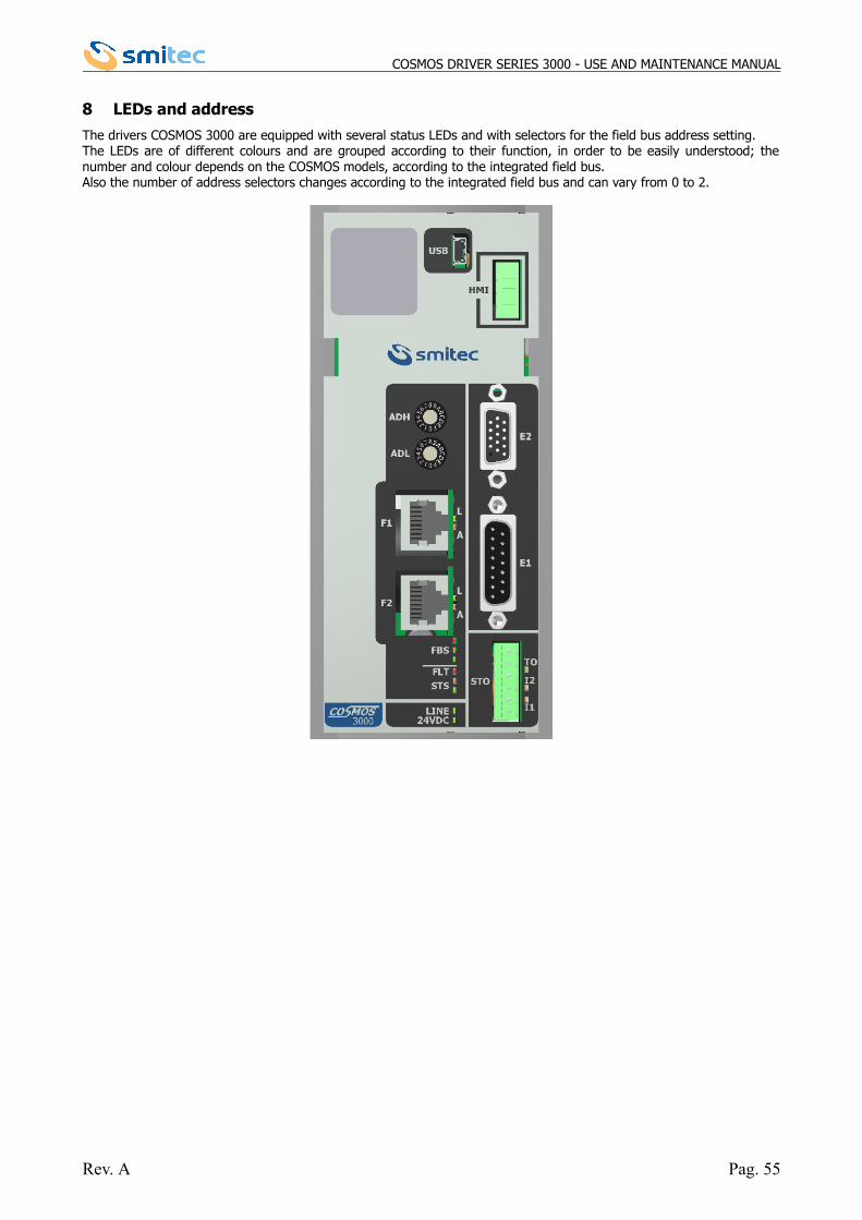
COSMOS DRIVER SERIES 3000 - USE AND MAINTENANCE MANUAL
8 LEDs and address
The drivers COSMOS 3000 are equipped with several status LEDs and with selectors for the field bus address setting. The LEDs are of different colours and are grouped according to their function, in order to be easily understood; thenumber and colour depends on the COSMOS models, according to the integrated field bus. Also the number of address selectors changes according to the integrated field bus and can vary from 0 to 2.
Rev. A Pag. 55
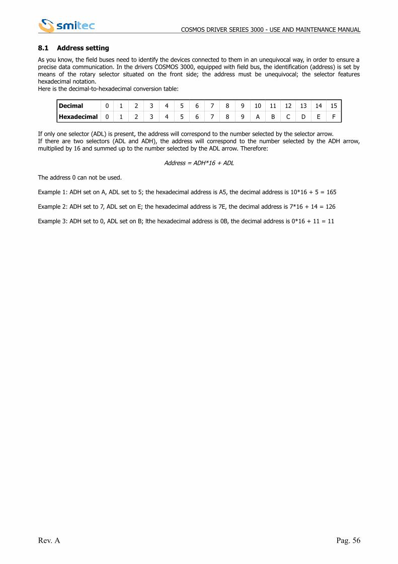
COSMOS DRIVER SERIES 3000 - USE AND MAINTENANCE MANUAL
8.1 Address setting
As you know, the field buses need to identify the devices connected to them in an unequivocal way, in order to ensure aprecise data communication. In the drivers COSMOS 3000, equipped with field bus, the identification (address) is set bymeans of the rotary selector situated on the front side; the address must be unequivocal; the selector featureshexadecimal notation.Here is the decimal-to-hexadecimal conversion table:
Decimal 0 1 2 3 4 5 6 7 8 9 10 11 12 13 14 15
Hexadecimal 0 1 2 3 4 5 6 7 8 9 A B C D E F
If only one selector (ADL) is present, the address will correspond to the number selected by the selector arrow.If there are two selectors (ADL and ADH), the address will correspond to the number selected by the ADH arrow,multiplied by 16 and summed up to the number selected by the ADL arrow. Therefore:
Address = ADH*16 + ADL
The address 0 can not be used.
Example 1: ADH set on A, ADL set to 5; the hexadecimal address is A5, the decimal address is 10*16 + 5 = 165
Example 2: ADH set to 7, ADL set on E; the hexadecimal address is 7E, the decimal address is 7*16 + 14 = 126
Example 3: ADH set to 0, ADL set on B; lthe hexadecimal address is 0B, the decimal address is 0*16 + 11 = 11
Rev. A Pag. 56
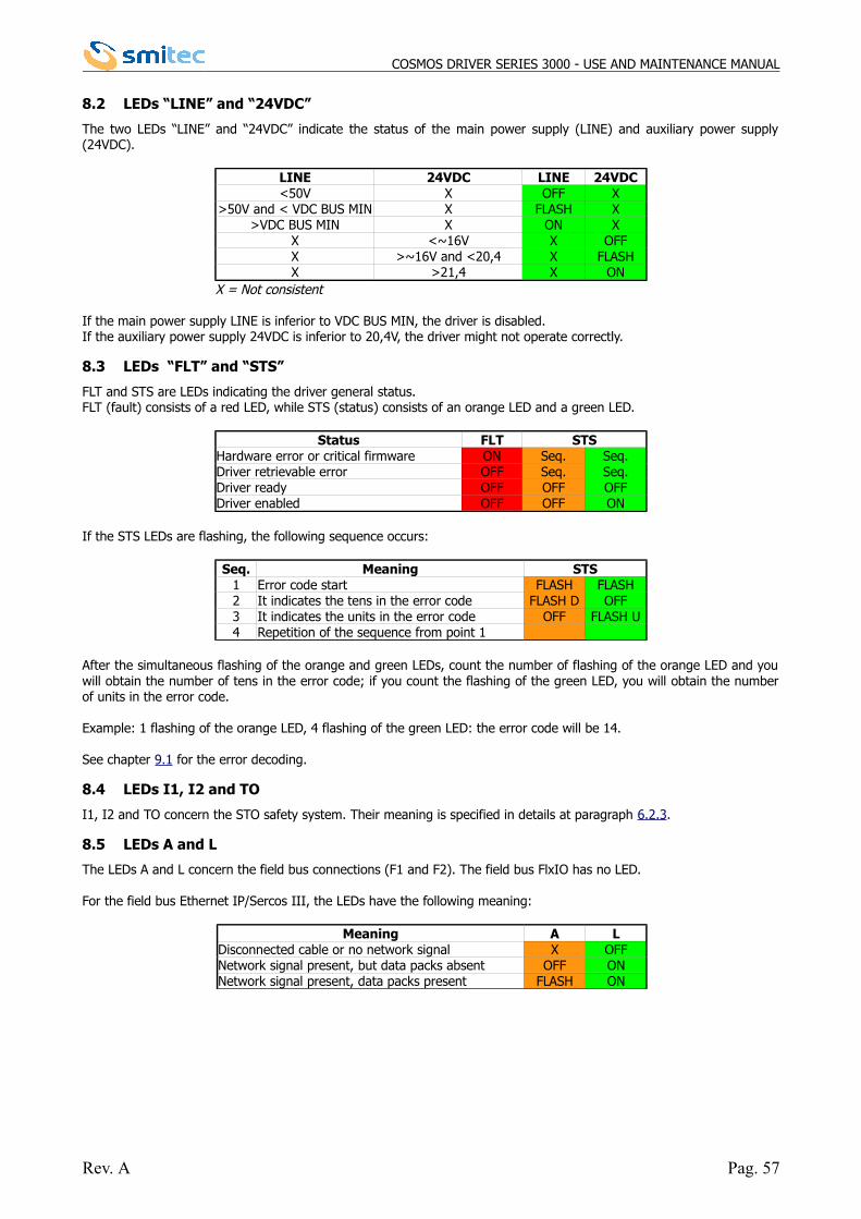
COSMOS DRIVER SERIES 3000 - USE AND MAINTENANCE MANUAL
8.2 LEDs “LINE” and “24VDC”
The two LEDs “LINE” and “24VDC” indicate the status of the main power supply (LINE) and auxiliary power supply(24VDC).
LINE 24VDC LINE 24VDC<50V X OFF X
>50V and < VDC BUS MIN X FLASH X>VDC BUS MIN X ON X
X <~16V X OFFX >~16V and <20,4 X FLASHX >21,4 X ON
X = Not consistent
If the main power supply LINE is inferior to VDC BUS MIN, the driver is disabled.If the auxiliary power supply 24VDC is inferior to 20,4V, the driver might not operate correctly.
8.3 LEDs “FLT” and “STS”
FLT and STS are LEDs indicating the driver general status.FLT (fault) consists of a red LED, while STS (status) consists of an orange LED and a green LED.
Status FLT STSHardware error or critical firmware ON Seq. Seq.Driver retrievable error OFF Seq. Seq.Driver ready OFF OFF OFFDriver enabled OFF OFF ON
If the STS LEDs are flashing, the following sequence occurs:
Seq. Meaning STS1 Error code start FLASH FLASH2 It indicates the tens in the error code FLASH D OFF3 It indicates the units in the error code OFF FLASH U4 Repetition of the sequence from point 1
After the simultaneous flashing of the orange and green LEDs, count the number of flashing of the orange LED and youwill obtain the number of tens in the error code; if you count the flashing of the green LED, you will obtain the numberof units in the error code.
Example: 1 flashing of the orange LED, 4 flashing of the green LED: the error code will be 14.
See chapter 9.1 for the error decoding.
8.4 LEDs I1, I2 and TO
I1, I2 and TO concern the STO safety system. Their meaning is specified in details at paragraph 6.2.3.
8.5 LEDs A and L
The LEDs A and L concern the field bus connections (F1 and F2). The field bus FlxIO has no LED.
For the field bus Ethernet IP/Sercos III, the LEDs have the following meaning:
Meaning A LDisconnected cable or no network signal X OFFNetwork signal present, but data packs absent OFF ONNetwork signal present, data packs present FLASH ON
Rev. A Pag. 57
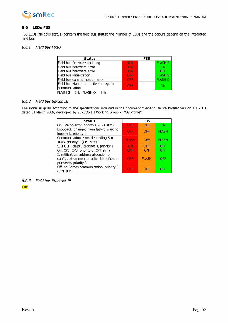
COSMOS DRIVER SERIES 3000 - USE AND MAINTENANCE MANUAL
8.6 LEDs FBS
FBS LEDs (fieldbus status) concern the field bus status; the number of LEDs and the colours depend on the integratedfield bus.
8.6.1 Field bus FlxIO
Status FBSField bus firmware updating ON FLASH SField bus hardware error ON ONField bus hardware error ON OFFField bus initialization OFF FLASH SField bus communication error OFF FLASH QField bus Master not active or regular communication
OFF ON
FLASH S = 1Hz, FLASH Q = 8Hz
8.6.2 Field bus Sercos III
The signal is given according to the specifications included in the document “Generic Device Profile” version 1.1.2.1.1dated 31 March 2009, developed by SERCOS III Working Group - TWG Profile”.
Status FBSOn,CP4 no error, priority 0 (CPT stm) OFF OFF ONLoopback, changed from fast-forward to loopback, priority 2
OFF OFF FLASH
Communication error, depending S-0-1003, priority 0 (CPT stm) FLASH OFF FLASH
SIII C1D, class 1 diagnosis, priority 1 ON OFF OFFOn, CP0..CP3, priority 0 (CPT stm) OFF ON OFFIdentification, address allocation or configuration error or other identification purposes, priority 3
OFF FLASH OFF
Off, no Sercos communication, priority 0 (CPT stm)
OFF OFF OFF
8.6.3 Field bus Ethernet IP
TBD
Rev. A Pag. 58
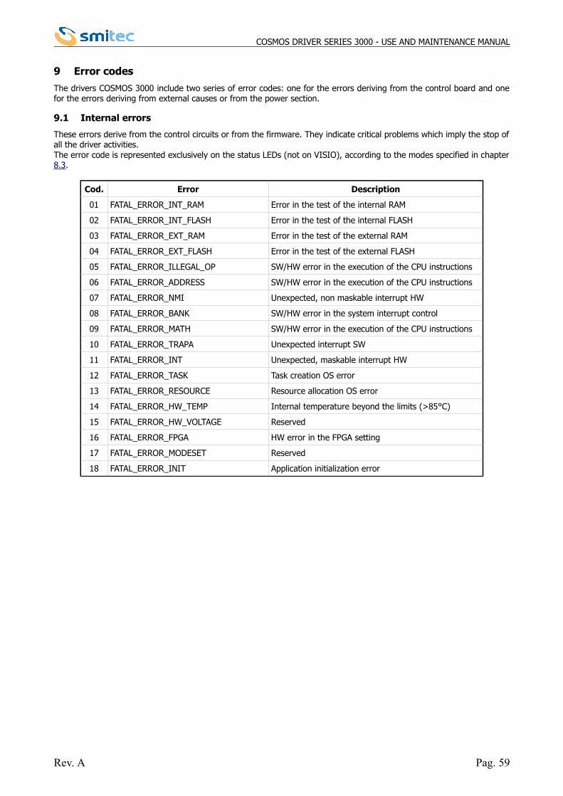
COSMOS DRIVER SERIES 3000 - USE AND MAINTENANCE MANUAL
9 Error codes
The drivers COSMOS 3000 include two series of error codes: one for the errors deriving from the control board and onefor the errors deriving from external causes or from the power section.
9.1 Internal errors
These errors derive from the control circuits or from the firmware. They indicate critical problems which imply the stop ofall the driver activities. The error code is represented exclusively on the status LEDs (not on VISIO), according to the modes specified in chapter8.3.
Cod. Error Description
01 FATAL_ERROR_INT_RAM Error in the test of the internal RAM
02 FATAL_ERROR_INT_FLASH Error in the test of the internal FLASH
03 FATAL_ERROR_EXT_RAM Error in the test of the external RAM
04 FATAL_ERROR_EXT_FLASH Error in the test of the external FLASH
05 FATAL_ERROR_ILLEGAL_OP SW/HW error in the execution of the CPU instructions
06 FATAL_ERROR_ADDRESS SW/HW error in the execution of the CPU instructions
07 FATAL_ERROR_NMI Unexpected, non maskable interrupt HW
08 FATAL_ERROR_BANK SW/HW error in the system interrupt control
09 FATAL_ERROR_MATH SW/HW error in the execution of the CPU instructions
10 FATAL_ERROR_TRAPA Unexpected interrupt SW
11 FATAL_ERROR_INT Unexpected, maskable interrupt HW
12 FATAL_ERROR_TASK Task creation OS error
13 FATAL_ERROR_RESOURCE Resource allocation OS error
14 FATAL_ERROR_HW_TEMP Internal temperature beyond the limits (>85°C)
15 FATAL_ERROR_HW_VOLTAGE Reserved
16 FATAL_ERROR_FPGA HW error in the FPGA setting
17 FATAL_ERROR_MODESET Reserved
18 FATAL_ERROR_INIT Application initialization error
Rev. A Pag. 59
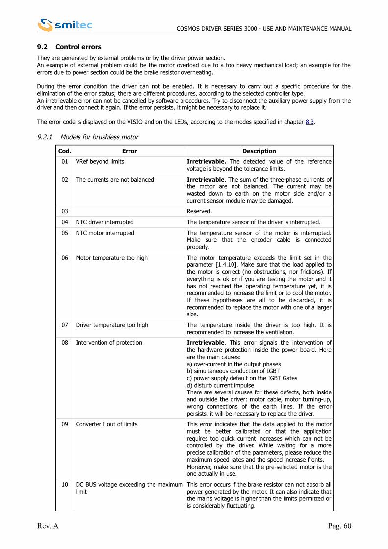
COSMOS DRIVER SERIES 3000 - USE AND MAINTENANCE MANUAL
9.2 Control errors
They are generated by external problems or by the driver power section. An example of external problem could be the motor overload due to a too heavy mechanical load; an example for theerrors due to power section could be the brake resistor overheating.
During the error condition the driver can not be enabled. It is necessary to carry out a specific procedure for theelimination of the error status; there are different procedures, according to the selected controller type. An irretrievable error can not be cancelled by software procedures. Try to disconnect the auxiliary power supply from thedriver and then connect it again. If the error persists, it might be necessary to replace it.
The error code is displayed on the VISIO and on the LEDs, according to the modes specified in chapter 8.3.
9.2.1 Models for brushless motor
Cod. Error Description
01 VRef beyond limits Irretrievable. The detected value of the referencevoltage is beyond the tolerance limits.
02 The currents are not balanced Irretrievable. The sum of the three-phase currents ofthe motor are not balanced. The current may bewasted down to earth on the motor side and/or acurrent sensor module may be damaged.
03 Reserved.
04 NTC driver interrupted The temperature sensor of the driver is interrupted.
05 NTC motor interrupted The temperature sensor of the motor is interrupted.Make sure that the encoder cable is connectedproperly.
06 Motor temperature too high The motor temperature exceeds the limit set in theparameter [1.4.10]. Make sure that the load applied tothe motor is correct (no obstructions, nor frictions). Ifeverything is ok or if you are testing the motor and ithas not reached the operating temperature yet, it isrecommended to increase the limit or to cool the motor.If these hypotheses are all to be discarded, it isrecommended to replace the motor with one of a largersize.
07 Driver temperature too high The temperature inside the driver is too high. It isrecommended to increase the ventilation.
08 Intervention of protection Irretrievable. This error signals the intervention ofthe hardware protection inside the power board. Hereare the main causes:a) over-current in the output phasesb) simultaneous conduction of IGBTc) power supply default on the IGBT Gatesd) disturb current impulseThere are several causes for these defects, both insideand outside the driver: motor cable, motor turning-up,wrong connections of the earth lines. If the errorpersists, it will be necessary to replace the driver.
09 Converter I out of limits This error indicates that the data applied to the motormust be better calibrated or that the applicationrequires too quick current increases which can not becontrolled by the driver. While waiting for a moreprecise calibration of the parameters, please reduce themaximum speed rates and the speed increase fronts.Moreover, make sure that the pre-selected motor is theone actually in use.
10 DC BUS voltage exceeding the maximumlimit
This error occurs if the brake resistor can not absorb allpower generated by the motor. It can also indicate thatthe mains voltage is higher than the limits permitted oris considerably fluctuating.
Rev. A Pag. 60
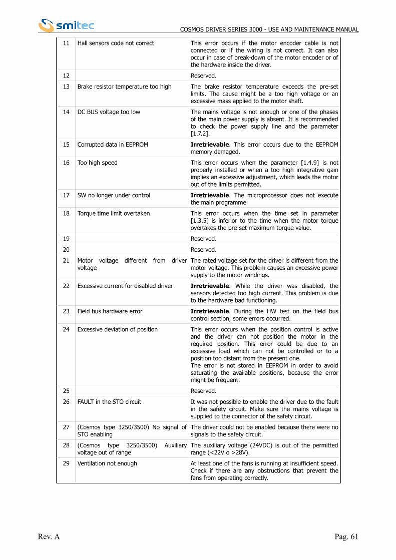
COSMOS DRIVER SERIES 3000 - USE AND MAINTENANCE MANUAL
11 Hall sensors code not correct This error occurs if the motor encoder cable is notconnected or if the wiring is not correct. It can alsooccur in case of break-down of the motor encoder or ofthe hardware inside the driver.
12 Reserved.
13 Brake resistor temperature too high The brake resistor temperature exceeds the pre-setlimits. The cause might be a too high voltage or anexcessive mass applied to the motor shaft.
14 DC BUS voltage too low The mains voltage is not enough or one of the phasesof the main power supply is absent. It is recommendedto check the power supply line and the parameter[1.7.2].
15 Corrupted data in EEPROM Irretrievable. This error occurs due to the EEPROMmemory damaged.
16 Too high speed This error occurs when the parameter [1.4.9] is notproperly installed or when a too high integrative gainimplies an excessive adjustment, which leads the motorout of the limits permitted.
17 SW no longer under control Irretrievable. The microprocessor does not executethe main programme
18 Torque time limit overtaken This error occurs when the time set in parameter[1.3.5] is inferior to the time when the motor torqueovertakes the pre-set maximum torque value.
19 Reserved.
20 Reserved.
21 Motor voltage different from drivervoltage
The rated voltage set for the driver is different from themotor voltage. This problem causes an excessive powersupply to the motor windings.
22 Excessive current for disabled driver Irretrievable. While the driver was disabled, thesensors detected too high current. This problem is dueto the hardware bad functioning.
23 Field bus hardware error Irretrievable. During the HW test on the field buscontrol section, some errors occurred.
24 Excessive deviation of position This error occurs when the position control is activeand the driver can not position the motor in therequired position. This error could be due to anexcessive load which can not be controlled or to aposition too distant from the present one. The error is not stored in EEPROM in order to avoidsaturating the available positions, because the errormight be frequent.
25 Reserved.
26 FAULT in the STO circuit It was not possible to enable the driver due to the faultin the safety circuit. Make sure the mains voltage issupplied to the connector of the safety circuit.
27 (Cosmos type 3250/3500) No signal ofSTO enabling
The driver could not be enabled because there were nosignals to the safety circuit.
28 (Cosmos type 3250/3500) Auxiliaryvoltage out of range
The auxiliary voltage (24VDC) is out of the permittedrange (<22V o >28V).
29 Ventilation not enough At least one of the fans is running at insufficient speed.Check if there are any obstructions that prevent thefans from operating correctly.
Rev. A Pag. 61
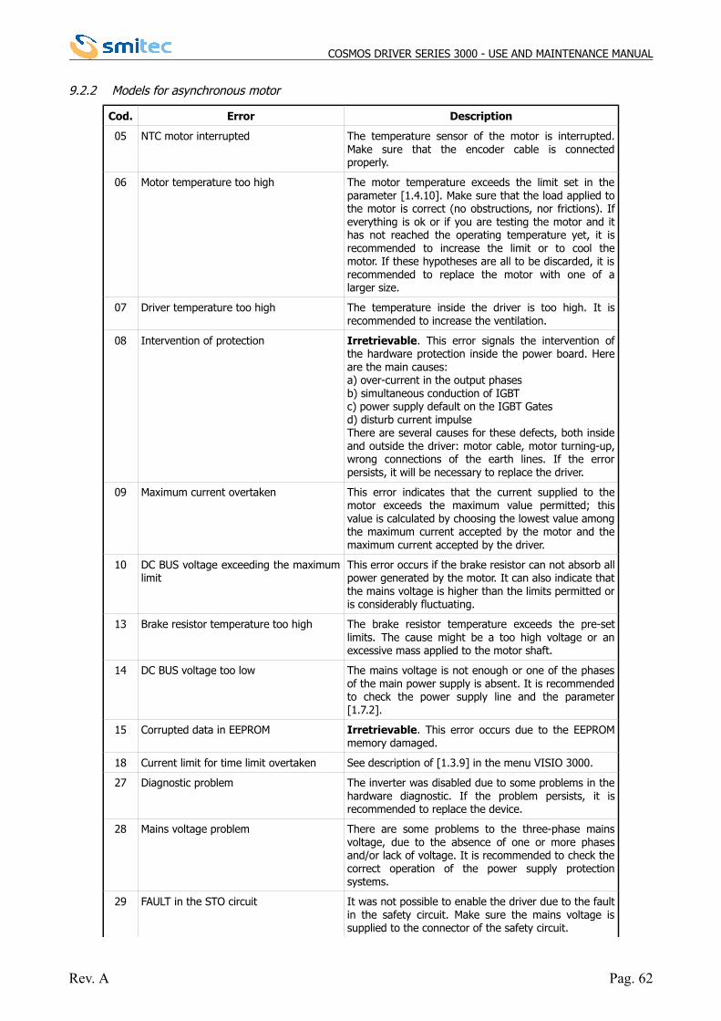
COSMOS DRIVER SERIES 3000 - USE AND MAINTENANCE MANUAL
9.2.2 Models for asynchronous motor
Cod. Error Description
05 NTC motor interrupted The temperature sensor of the motor is interrupted.Make sure that the encoder cable is connectedproperly.
06 Motor temperature too high The motor temperature exceeds the limit set in theparameter [1.4.10]. Make sure that the load applied tothe motor is correct (no obstructions, nor frictions). Ifeverything is ok or if you are testing the motor and ithas not reached the operating temperature yet, it isrecommended to increase the limit or to cool themotor. If these hypotheses are all to be discarded, it isrecommended to replace the motor with one of alarger size.
07 Driver temperature too high The temperature inside the driver is too high. It isrecommended to increase the ventilation.
08 Intervention of protection Irretrievable. This error signals the intervention ofthe hardware protection inside the power board. Hereare the main causes:a) over-current in the output phasesb) simultaneous conduction of IGBTc) power supply default on the IGBT Gatesd) disturb current impulseThere are several causes for these defects, both insideand outside the driver: motor cable, motor turning-up,wrong connections of the earth lines. If the errorpersists, it will be necessary to replace the driver.
09 Maximum current overtaken This error indicates that the current supplied to themotor exceeds the maximum value permitted; thisvalue is calculated by choosing the lowest value amongthe maximum current accepted by the motor and themaximum current accepted by the driver.
10 DC BUS voltage exceeding the maximumlimit
This error occurs if the brake resistor can not absorb allpower generated by the motor. It can also indicate thatthe mains voltage is higher than the limits permitted oris considerably fluctuating.
13 Brake resistor temperature too high The brake resistor temperature exceeds the pre-setlimits. The cause might be a too high voltage or anexcessive mass applied to the motor shaft.
14 DC BUS voltage too low The mains voltage is not enough or one of the phasesof the main power supply is absent. It is recommendedto check the power supply line and the parameter[1.7.2].
15 Corrupted data in EEPROM Irretrievable. This error occurs due to the EEPROMmemory damaged.
18 Current limit for time limit overtaken See description of [1.3.9] in the menu VISIO 3000.
27 Diagnostic problem The inverter was disabled due to some problems in thehardware diagnostic. If the problem persists, it isrecommended to replace the device.
28 Mains voltage problem There are some problems to the three-phase mainsvoltage, due to the absence of one or more phasesand/or lack of voltage. It is recommended to check thecorrect operation of the power supply protectionsystems.
29 FAULT in the STO circuit It was not possible to enable the driver due to the faultin the safety circuit. Make sure the mains voltage issupplied to the connector of the safety circuit.
Rev. A Pag. 62
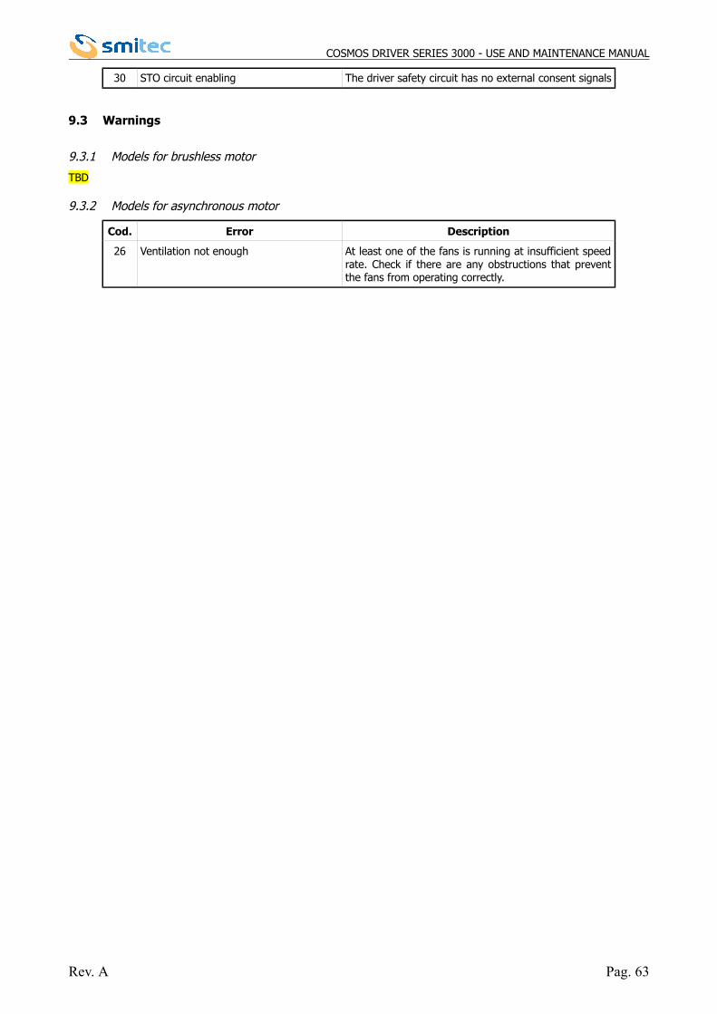
COSMOS DRIVER SERIES 3000 - USE AND MAINTENANCE MANUAL
30 STO circuit enabling The driver safety circuit has no external consent signals
9.3 Warnings
9.3.1 Models for brushless motor
TBD
9.3.2 Models for asynchronous motor
Cod. Error Description
26 Ventilation not enough At least one of the fans is running at insufficient speedrate. Check if there are any obstructions that preventthe fans from operating correctly.
Rev. A Pag. 63