Embed Size (px)
Citation preview

Cost 297HAPCOS Meeting, Friedrichshafen, Germany
Oct. 8 – 10, 2008
Communications to and from HAPs –with laser beams?
Walter [email protected]
Vienna University of TechnologyInstitute of Communications and Radio-Frequency Engineering
Gusshausstrasse 25/389, 1040 Vienna

2W. Leeb Oct. 8, 2008
Overview
• Introduction
• Building blocks
• PAT
• Influence of channel (= atmosphere)
• Bandwidth offered by optical and microwave links
• Summary

3W. Leeb Oct. 8, 2008
Motivation for optical links
transmission bandwidth f
(small) percentage of carrier frequency f
f = 200 to 350 THz
f 300 GHz
beam divergence proportional to 1/f
(antenna gain G proportional to f2)
10 rad, G 130 dB
small antenna diameter
expecting:
low terminal mass
low power consumption

4W. Leeb Oct. 8, 2008
Basic differences to microwave links
so far no frequency regulations
no electromagnetic interference
difficult eavesdropping
quantum nature dominates (hf >> kT)
dimension of devices (D >> )
antenna pointing, terminal acquisition, mutual tracking (PAT)
( two-way optical link)
influence of atmosphere
background radiation (Sun, Moon, etc.)
h ... Planck's constantk ... Boltzmann's constantT ... system temperature

5W. Leeb Oct. 8, 2008
Scenarios
GEO ... geostationary orbitLEO ... low earth orbitISS ... International Space Station
distance L = 45 000 to 83 000 km
data rate R = 3 Gbit/s
distance L > 1 000 000 km
data rate R = 2 Mbit/s
6W. Leeb Oct. 8, 2008
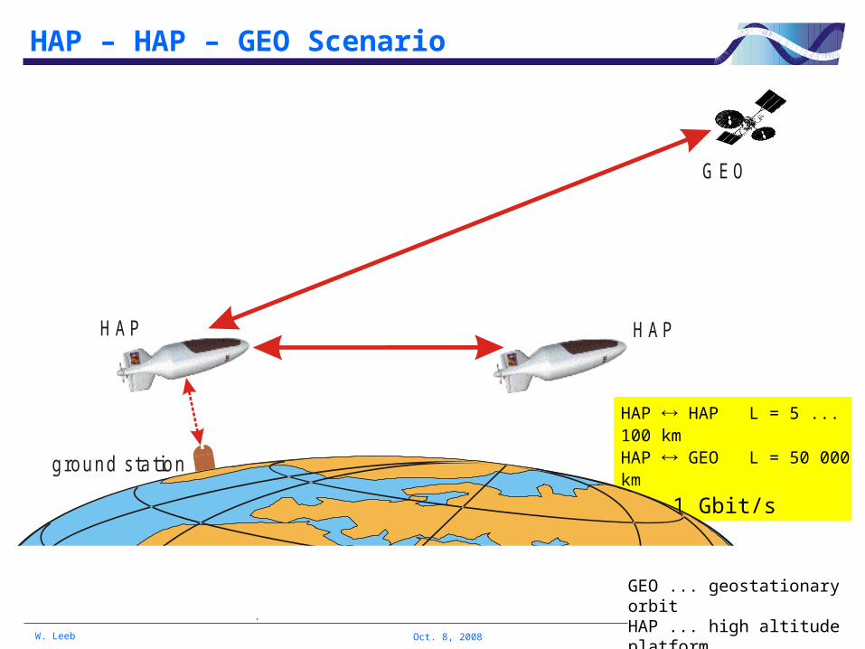
HAP – HAP – GEO Scenario
GEO ... geostationary orbitHAP ... high altitude platform
HAP HAP L = 5 ... 100 kmHAP GEO L = 50 000 km
R = 1 Gbit/s
G EO
H AP H AP
ground station

7W. Leeb Oct. 8, 2008
LEO-GEO link
2001
European Space Agency
ARTEMIS (GEO) SPOT-4 (LEO)
mean distance: 40 000 km
= 0.85 µm
R = 50 Mbit/s [2 Mbit/s]
2005
ARTEMIS OICETS (LEO, Japan)
SILEX ... Semiconductor Laser Intersatellite Link Experiment
ARTEMIS
SPOT 4

8W. Leeb Oct. 8, 2008
Balloon-to-ground link
2005German Aerospace Centre (EU project CAPANINA)
STROPEX
balloon (at 22 km) to ground, distance = 64 km
= 1.5 µm (InGaAs diode laser)
R = 622 Mbit/s and 1.25 Gbit/s

9W. Leeb Oct. 8, 2008
Airplane to GEO satellite
2006European Space Agency, France
"LOLA"
airplane (10 km height) to ARTEMIS (GEO)
= 0.85 µm, diode laser
successful pointing and tracking, video transmission

10W. Leeb Oct. 8, 2008
LEO-LEO link
2008
intersatellite laser communication:
TerraSAR-X (LEO, Germany) NFIRE (LEO, USA), 5 000 km
= 1.06 µm (Nd:YAG laser)
coherent receiver (homodyne)
BPSK (binary phase shift keying)
R = 5.5 Gbit/s

11W. Leeb Oct. 8, 2008
Overview
• Introduction
• Building blocks
• PAT
• Influence of channel (= atmosphere)
• Bandwidth offered by optical and microwave links
• Summary

12W. Leeb Oct. 8, 2008
Optical transceiver for space missions
transm itter(laser +
m odulator)
receiver
te lescope(antenna)
inTX
data
R Xdata
electrica l s ignal
fine poin ting
coarsepointing
aquisition andtracking sensor
pointahead
contro ll s ignal
optica l output s ignal
optica l input s ignal

13W. Leeb Oct. 8, 2008
TX, RX for = 0.85 µm
direct modulation
APD ... avalanche photodiode
diode laser0.85 µm
TX data
optica l output power PT
optics
APD photodiodem odule
decisionlogic
data
optica l input pow er P R
optica lbandpassoptics

14W. Leeb Oct. 8, 2008
TX, RX for = 1.5 µm
EDFA ... Erbium doped fiber amplifier
diode laser1.55 µm
externalm odulator
boosterED FA optica l output
pow er PT
optics
TX data
pream plifierED FA
optica lbandpass
PIN photodiodem odule
decis ionlogic
data
optica l input pow er P R
optics

15W. Leeb Oct. 8, 2008
Input-output multiplexing (1)
duplexing: spectrally, or via polarization, or both
to keep crosstalk TX RX low: high isolation within duplexer
(e.g. PT = 1 W, PR = 10 nW) 95 dB
duplex operation between two moving terminals required,at least for acquisition and tracking
receiver
transm itter
duplexer
te lescope(antenna)
optical beam in
optical beam out
(PR)
(PT)
single antenna for RX and TX

16W. Leeb Oct. 8, 2008
Input-output multiplexing (2)
receiver
transm itterte lescope(antenna)
optica l beam in (PR )
optica l beam out (PT)
m irror
simple duplexing scheme
increased telescope diameter
shared antenna aperture

17W. Leeb Oct. 8, 2008
Overview
• Introduction
• Building blocks
• PAT
• Influence of channel (= atmosphere)
• Bandwidth offered by optical and microwave links
• Summary
18W. Leeb Oct. 8, 2008
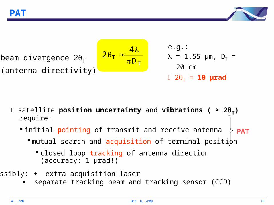
PAT
e.g.:
= 1.55 µm, DT = 20 cm
2T = 10 µradT
T D
42
satellite position uncertainty and vibrations ( > 2T) require:
initial pointing of transmit and receive antenna
mutual search and acquisition of terminal position
closed loop tracking of antenna direction (accuracy: 1 µrad!)
beam divergence 2T
(antenna directivity)
PAT
possibly: extra acquisition laser separate tracking beam and tracking sensor (CCD)

19W. Leeb Oct. 8, 2008
Overview
• Introduction
• Building blocks
• PAT
• Influence of channel (= atmosphere)
• Bandwidth offered by optical and microwave links
• Summary

20W. Leeb Oct. 8, 2008
Influence of atmosphere
absorption by molecules attenuation
scattering (molecules, waterdroplets, fog, snow) attenuation
pronounced influence within first 15 km above the Earth's surface,
but relatively small influence above 15 km
turbulence (random variation of index of refraction)
increased beam divergence ("beam spread" & "breathing" of beam) attenuation, fading
random beam deflection ("beam wander") fading
phase front distortion fading, scintillation

21W. Leeb Oct. 8, 2008
Beam spread
r0 ... Fried-Parameter
... wavelength
diffraction limited beam divergence in vacuum T
DL D
4
2
beam divergence including influence of turbulence2
0
2DLturb r
2)2(2
far field:
θ tu rb
w e ff
sp o t-s izew ith tu rb u len ce
x
y
θ D L
w 0D T
tran sm itte r f ie ld
n ea r-fie ld
fa r-fie ld
w D L
sp o t-s izew ith o u t tu rb u len ce

22W. Leeb Oct. 8, 2008
Fried parameter
Fried parameter r0 characterises the degree of turbulence, integrated over beam path
large r0 means little influence of turbulence
examples (medium turbulence, = 1.5 m):
- HAP(at 17 km)-to-satellite link r0 = 10 m
- ground-to-satellite link r0 = 15 cm
for a transmit antenna diameter DT equal to the Fried parameter r0,
the turbulence causes an increase of the divergence by a factor of ,
i.e. a gain reduction by 3 dB
2
- downlink (satellite to HAP): in general negligible influence of turbulence
- uplink: typically < 0.1 dB additional loss due to turbulence-induced beam spread

23W. Leeb Oct. 8, 2008
Beam wander
caused by large-scale turbulence near the transmitter,
leading to deflection of entire beam
y
x
w ith o u ttu rb u len ce
w ithtu rb u len ce

24W. Leeb Oct. 8, 2008
Scintillation
caused by small-scale turbulence, leads to interference between parts of the beam,
disturbance of intensity profile ("speckle") distortion of beam phasefront, mode de-composition ( reduced coupling into single-mode receiver)
scintillation index 2 characterises the temporal behaviour of intensity (I) fluctuations (normalized variance of I(t))
1I
I
2
2
2 typically 2 < 0.025 for HAP-to-satellite link temporal mean
b eam p h ase fro n tw ith o u t
tu rb u len ce
r
b eam in ten s ity
r
w ithtu rb u len ce

25W. Leeb Oct. 8, 2008
Overview
• Introduction
• Building blocks
• PAT
• Influence of channel (= atmosphere)
• Bandwidth offered by optical and microwave links
• Summary

26W. Leeb Oct. 8, 2008
Sensitivity of receivers
rule of thumb for detecting one bit of information:
required is an energy of either 10 hf or 10 kT, whatever is larger
10 hf 10 kT
optical = 1 µm, T = 300 K
210-18 Ws 410-20 Ws
microwavef = 10 GHz, T = 300 K 710-23 Ws 410-20 Ws
h ... Planck`s constantk ... Boltzmann`s constantT ... system temperature
optical regime requires 100 times larger input power!
Optical on-off keying: BEP = 10-9 requires an average of 10 photons per bit
(absolute physical limit)

27W. Leeb Oct. 8, 2008
Background radiation
sources: Sun, Moon, planets (including Earth), scattering atmosphere
received background power PB = NbackBom
Optical links: noise increase due to background
Nback ... power density (in one spatial mode)
e.g. at = 1.5 m - Nback,Sun = 410-20 W/Hz
- Nback,Earth = 410-25 W/Hz
- Nback,atm@20 km = 10-27 W/Hz
Bo ... bandwidth of optical filter [Hz]
m ... number of modes accepted by receiver

28W. Leeb Oct. 8, 2008
Transmission bandwidth - examples
HAP (20 km) GEO satellite (36 000 km)
distance L = 50 000 km (zenith angle 45°)
TX: GaAs laser diode
RX: avalanche photodiode
TX: InGaAs laser diode
RX: EDFA reamplifierRF in K-band
wavelength 0.85 µm 1.55 µm 1.76 cm
carrier frequency 353 THz 194 THz 17 GHz
achievable bandwidth B for optical and RF links = ?
29W. Leeb Oct. 8, 2008
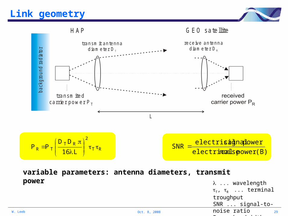
Link geometry
RT
2RT
TR L16
DDPP
(B)powernoiseelectrical
powersignalelectricalSNR
variable parameters: antenna diameters, transmit power
L
transm it antennadiam eter D T
G EO sate llite
receive antennadiam eter D R
H AP
transm ited pow er P T carrier
back
gro
und
ra
diat
or
... wavelengthT, R ... terminal troughputSNR ... signal-to-noise ratioB ... bandwidth

30W. Leeb Oct. 8, 2008
Bandwidth
PT = 10 W
L = 50 000 km, SNR = 16 dB
RF: f = 17 GHz, RR = 0.35, noise figure 3 dB,
PT = 10 W
e.g. DT = 2.8 m DR = 2.0 m
= 1 W
product of antenna d iam eters, D ·D [m ]T R
2
0.01 0 .1 1 10
achi
evab
le b
andw
idth
B
10 G H z
1 G H z
100 M H z
10 M H z
1 M H z

31W. Leeb Oct. 8, 2008
Bandwidth
PT = 10 W
Optical: = 0.85 µm, RR = 0.25, MAPD,opt, in.el = 12 pA/Hz, Nback = 2·10-25 W/Hz, Bopt= 1nm
RF: f = 17 GHz, RR = 0.35, noise figure 3 dB,
PT = 10 W
e.g. DT = 2.8 m DR = 2.0 m
= 1 W
product of antenna d iam eters, D ·D [m ]T R
2
0.01 0 .1 1 10
achi
evab
le b
andw
idth
B
10 G H z
1 G H z
100 M H z
10 M H z
1 M H z
PT = 0.1 W
L = 50 000 km, SNR = 16 dB

32W. Leeb Oct. 8, 2008
Bandwidth
PT = 10 W
Optical: = 0.85 µm, RR = 0.25, MAPD,opt, in,el = 12 pA/Hz, Nback = 2·10-25 W/Hz, Bopt= 1nm
RF: f = 17 GHz, RR = 0.35, noise figure 3 dB,
Optical: = 1.55 µm, RR = 0.25, in,el = 12 pA/Hz, Nback = 4·10-25 W/Hz, Bopt= 0.5 nm
PT = 10 W
e.g. DT = 2.8 m DR = 2.0 m
e.g. DT = 14 cm DR = 23 cm
= 1 W
product of antenna d iam eters, D ·D [m ]T R
2
0.01 0 .1 1 10
achi
evab
le b
andw
idth
B
10 G H z
1 G H z
100 M H z
10 M H z
1 M H z
= 0.3 W
PT = 0.1 W
PT = 1 W
L = 50 000 km, SNR = 16 dB

33W. Leeb Oct. 8, 2008
Antenna gain and beam spread loss
HAP(at 20 km)-to-GEO uplink, = 1.5 µm
transm it te lescope d iam eter D [m ]TX
ante
nna
gain
[dB
]
105
107
109
111
113
0.1 0.15 0.2 0.25
antenna gain
antenna gain minus beam spread loss, hHAP = 20 km
antenna gain minus beam spread loss, hHAP = 1 km

34W. Leeb Oct. 8, 2008
Sun as background
SNR degradationdue to sun
as background[dB]
APD receiver(large field-of-view)
15
10
5
0
16 dB
EDFA receiver(single transverse mode)
0.7 dB
Nback = 410-20 W/Hz

35W. Leeb Oct. 8, 2008
20 km 20 km
400 km
20 km
10 km
100 km
dow n
up
Beam spread loss (bs) for HAP-to-HAP links
= 1.55 µm, DT = DR = 13,5 cm
bs = 0.3 dB ... up, medium turbulence
bs = 0.7 dB ... down, medium turbulence
bs = 0.3 dB ... weak turbulence
bs = 0.7 dB ... strong turbulence
bs with DT, because ratio DT/diameter of turbulent eddies ... but much less than antenna gain!

36W. Leeb Oct. 8, 2008
Entangled photons for cryptography
Alice
Bob
aim: global distribution of cryptographic keys using a source of entangled photons onboard the International Space Station (ISS)
or on a HAP?

37W. Leeb Oct. 8, 2008
Summary
large bandwidth obtainable with low antenna diameter small prime power (?) compact terminal (?)
challenges mutual acquisition, tracking of terminals
strategies towards implementation adapt demonstrated systems and technologies systems should have potential for further development
very small disturbance by atmosphere for HAP GEO link (zenith angle < 45°) HAP HAP link (hHAP = 20 km)


![Why to reduce dwell time?€¦ · Dr. Bernhard Rüger / bernhard.rueger@tuwien.ac.at / DI. Doris Tuna / doris.tuna@tuwien.ac.at ideale Zeit [sec] 0,0 25,0 50,0 125,0 100,0 75,0 50,0](https://img.pdfslide.net/doc/110x75/6082292dff2bb02f1320972e/why-to-reduce-dwell-time-dr-bernhard-rger-bernhardruegertuwienacat-di.jpg)