Embed Size (px)
Citation preview

ESTCPCost and Performance Report
EnvironmEntal SEcuritytEchnology cErtification Program
u.S. Department of Defense
(MM-0032)
Decontamination of Explosives-Contaminated Range Scrap Using A Transportable Hot Gas Decontamination (HGD) System Cost and Performance Report
January 2007

i
COST & PERFORMANCE REPORT ESTCP Project: MM-0032
TABLE OF CONTENTS
Page
1.0 EXECUTIVE SUMMARY ........................................................................ 1 1.1 BACKGROUND............................................................................ 1 1.2 OBJECTIVE OF THE DEMONSTRATION.......................................... 1 1.3 REGULATORY DRIVERS............................................................... 1 1.4 DEMONSTRATION RESULTS......................................................... 2 1.5 STAKEHOLDER/END-USER ISSUES................................................ 3
2.0 TECHNOLOGY DESCRIPTION ................................................................ 5 2.1 TECHNOLOGY DEVELOPMENT AND APPLICATION........................ 5 2.2 PROCESS DESCRIPTION ............................................................... 5 2.3 PREVIOUS TESTING OF THE TECHNOLOGY ................................... 7 2.4 ADVANTAGES AND LIMITATIONS ................................................ 8
3.0 DEMONSTRATION DESIGN...................................................................11 3.1 PERFORMANCE OBJECTIVES.......................................................11 3.2 SELECTION OF TEST SITE ...........................................................12 3.3 TEST SITE HISTORY/CHARACTERISTICS.......................................12 3.4 PHYSICAL SETUP AND OPERATION .............................................12 3.5 SAMPLING/MONITORING PROCEDURES .......................................14
4.0 PERFORMANCE ASSESSMENT ..............................................................17 4.1 PERFORMANCE DATA ................................................................17 4.2 PERFORMANCE CRITERIA ..........................................................17 4.3 HGD SYSTEM PERFORMANCE ASSESSMENT.................................19 4.4 TECHNOLOGY COMPARISON ......................................................22
5.0 COST ASSESSMENT .............................................................................23 5.1 EXPECTED OPERATIONAL COST .................................................23
5.1.1 Cost Data from Demonstration .................................................23 5.1.2 Operational Cost ..................................................................27
6.0 IMPLEMENTATION ISSUES AND LESSONS LEARNED ..............................33 6.1 GENERAL..................................................................................33 6.2 EQUIPMENT AND MATERIALS ....................................................33
6.2.1 Burner System.....................................................................33 6.2.2 Thermocouples ....................................................................34 6.2.3 Insulation Materials and Installation...........................................34
6.3 UTILITIES..................................................................................36

TABLE OF CONTENTS (continued)
Page
ii
6.4 SECURITY .................................................................................36 6.5 APPROACH TO REGULATORY COMPLIANCE AND ACCEPTANCE....37
7.0 REFERENCES......................................................................................39 APPENDIX A: POINTS OF CONTACT......................................................................... A-1

iii
LIST OF FIGURES
Page Figure 1 Transportable Hot Gas Decontamination System and Insulation Blanket........... 5 Figure 2 Process Schematic................................................................................................ 6 Figure 3 Shielded Diesel-Powered Generator and 500-Gallon Auxiliary Tank ................ 7 Figure 4 Propane Burner .................................................................................................... 12 Figure 5 Operator Workstation........................................................................................... 12 Figure 6 Shielded Diesel-Powered Generator and 500-Gallon Auxiliary Tank ................ 13 Figure 7 Shielded Propane Fuel Tanks............................................................................... 13 Figure 8 K-Type Thermocouple......................................................................................... 13 Figure 9 Wire Mesh............................................................................................................ 13 Figure 10 Thermal Blankets ................................................................................................. 13 Figure 11 Chicken Wire ....................................................................................................... 14 Figure 12 Top View of Spiked Coupon Box........................................................................ 14 Figure 13 Thermocouple Locations ..................................................................................... 15
LIST OF TABLES
Page Table 1 Performance Objectives and Assessment ............................................................. 11 Table 2 Sampling and Analysis Methodology for HGD.................................................... 16 Table 3 Test-Specific Objectives and Assessment ............................................................ 17 Table 4 Performance Criteria............................................................................................. 18 Table 5 HGD Pile Insulation.............................................................................................. 24 Table 6 HGD Total Square Footage and Cost per Trial .................................................... 25 Table 7 HGD Total Costs Over Seven Trials .................................................................... 26 Table 8 Mobilization Cost Breakdown .............................................................................. 27 Table 9 Operational HGD Insulation and Wire Materials Quantities and Associated
Costs...................................................................................................................... 28 Table 10 Start-Up Cost Estimate ......................................................................................... 29 Table 11 Full Production Cost Estimate .............................................................................. 30 Table 12 A 15,000-Ton Site Cost Comparison.................................................................... 31

iv
ACRONYMS AND ABBREVIATIONS AAQMP Ambient Air Quality Management Program ABR-9 Air Base Range 9 AEC U.S. Army Environmental Center AEDA ammunition, explosives, and dangerous articles APG Aberdeen Proving Ground ASTM American Society for Testing and Materials ATC Aberdeen Testing Center Btu British thermal unit CAD computer-aided design CFR Code of Federal Regulations CHPPM Center for Health Promotion and Preventive Medicine CO carbon monoxide CO2 carbon dioxide COMAR Code of Maryland Regulations CRREL Cold Regions Research and Engineering Laboratory CTT closed, transferred, and transferring DoD Department of Defense EPA Environmental Protection Agency ESTCP Environmental Security Technology Certification Program HBX high blast explosive HGD hot gas decontamination JHA job hazard analysis MDE Maryland Department of the Environment MMR Military Munitions Rule MSDS Material Safety Data Sheets NEMA National Electric Manufacturers Association NEPA National Environmental Policy Act NFPA National Fire Protection Agency NOx nitrogen oxide OW operator workstation PAH polycyclic aromatic hydrocarbon PLC programmable logic controller PM10 particulate matter with an aerodynamic diameter less than or equal to 10 microns

ACRONYMS AND ABBREVIATIONS (continued)
v
PM2.5 particulate matter with an aerodynamic diameter less than or equal to 2.5 microns PPE personal protective equipment R3 Resource Recovery and Recycling RCRA Resource Conservation and Recovery Act RDX Royal Demolition Explosives or Research Department Explosives RRCF Range Residue Consolidation Facility SO2 sulfur dioxide SOP standard operating procedure SVOC semivolatile organic compounds TIR test incident report TNT trinitrotoluene TSP total suspended particulate TSP total suspended particulates UXO unexploded ordnance VOC volatile organic compounds XAD experimental and developmental Yellow D Ammonium picrate

vi
ACKNOWLEDGEMENTS Many individuals and organizations contributed to the development and demonstration of Decontamination of Explosives-Contaminated Range Scrap Using A Transportable Hot Gas Decontamination (HGD) System. The Environmental Security Technology Certification Program (ESTCP) and the U.S. Army Environmental Center (USAEC) funded this project. Mr. Alan Hewitt of the U.S. Army Cold Regions Research and Engineering Laboratory fabricated and analyzed the spiked coupons used during the HGD process to evaluate the decontamination. Mr. Michael Chapman and Ms. Gwen McKinney of the U.S. Army Aberdeen Test Center (ATC) Chemistry Team in conjunction with Mr. David J. Gilbride and Mr. Joseph B. Sutphin of the Air Quality Surveillance Program and Mr. David Morrow of the Directorate of Laboratory Services of U.S. Army Center for Health Promotion and Preventive Medicine planned and executed the data collection, analysis, and reporting of the fugitive emissions portion of this demonstration. Mr. Donald Beck and Mr. Robert Putt of the Hauck Manufacturing Company manufactured and helped field the 2.5 million Btu propane-fired HGD burner system. Ms. Deborah L. Furnari was the ATC lead for this demonstration and could not have successfully completed the test execution phase of this demonstration without the assistance of Mr. Jason Jack monitoring the HGD system. Prior to and during the demonstration, safety issues were resolved and coordinated through Mr. Mark Kiefer and Mr. Derrick Butler of the ATC Safety Team; environmental issues were resolved and coordinated through Mr. Larry Overbay of the ATC Environmental Team; and any personal protective equipment issues were resolved and coordinated through Ms. Heather Hilton of the Industrial Hygiene Office of the Kirk U.S. Army Health Clinic. Mr. Samuel Dixon, Mr. Michael Petit, Mr. Charles Sexton, and Mr. Walter Vuncannon of the ATC Environmental Team were instrumental in gathering the explosively contaminated range scrap needed for this demonstration. Mr. Paul Klara of the Military Environmental Technology Demonstration Center (METDC) of ATC and Mr. Chas Simpson of the Aberdeen Test Support Services (ATSS) designed and fabricated the bridge that was used to suspend the emissions monitors 10 feet over the pile of scrap. Thanks to Mr. Jason Jack of METDC and to Mr. Cleveland Foster of ATSS for their help in reducing the test data and writing sections of the HGD Report. Lastly, thanks are extended to these and all those who, with considerable physical effort, toiled to construct and to maintain Air Base Range 9 in support of this demonstration.
Technical material contained in this report has been approved for public release.

1
1.0 EXECUTIVE SUMMARY 1.1 BACKGROUND The Department of Defense (DoD) has numerous target, bombing, test, and firing ranges that have accumulated a substantial amount of recyclable scrap metal in the form of range residue. This scrap metal includes practice bombs, expended artillery, small arms and mortar projectiles, aircraft bombs and missiles, rockets and rocket motors, hard targets, grenades, incendiary devices, experimental items, demolition devices, and other materials fired on or upon a military range. This material is collected in range sweeps and removal operations at active ranges, and unexploded ordnance (UXO) removal operations at Closed, Transferred, and Transferring (CTT) sites. Testing performed during this demonstration revealed that these items often have explosives residue after detonation. Explosive incidents involving scrap metal from training and firing ranges have occurred over the years and recently have come under close scrutiny. A safe, environmentally conscious alternative to decontaminate firing range scrap is a low-temperature thermal desorption process called the hot gas decontamination (HGD) technology developed by the U.S. Army Environmental Center (AEC). The HGD technology uses controlled heat to volatilize and thermally decompose the explosives contamination. A low-cost HGD process configuration was demonstrated in which the scrap metal was placed in piles and covered with an insulated thermal blanket. A propane-fired portable burner injected heat at a controlled rate to meet the time and temperature criteria of up to 600oF for up to a 6-hour holding time, to reach a decontamination level. Range residue had not previously been decontaminated in this manner to date. 1.2 OBJECTIVE OF THE DEMONSTRATION The objective of this project was to demonstrate the safe and effective decontamination of range scrap materials at the lowest possible cost. Using commercially available equipment and materials, this project demonstrated an effective, safe, temporary, and portable hot gas system for decontaminating explosives-contaminated range scrap materials. Currently, the high costs associated with establishing and maintaining permanent hot-gas decontamination structures has made the technology unattainable for many installations. 1.3 REGULATORY DRIVERS Federal, state, local and Army regulations were applicable in the developmental stages of the HGD demonstration and will apply in its implementation. These regulations include federal laws such as the Resource Conservation and Recovery Act (RCRA), the Military Munitions Rule (MMR), the Clean Air Act, and other local and Army regulations, which are summarized below. RCRA and Military Munitions Rule. The range scrap used in this demonstration was gathered from ATC ranges. Scrap generated during training and testing on the range is defined as range residue and must be managed in accordance with DoD 4160.21-M, Chapter 4. [1] The range residue at ATC is exempt from solid waste disposal regulations due to being recycled. Some of these items were found to contain trace quantities of explosive residue and were certified as non-

2
reactive thus, they were ideal test items for the HGD demonstration. Therefore, in this particular case, HGD does not constitute hazardous waste treatment. Expended military munitions used in the HGD demonstration are addressed by the Military Munitions Rule (Environmental Protection Agency [EPA] Munitions Rule) published in 1997. The EPA Munitions Rule is codified at 40 Code of Federal Regulations (CFR) Parts 260 through 266 and Part 270. [2] Section 266.202 states that military munitions are not a solid waste when used in military training exercises, weapons testing, and range clearance operations. Scrap metal items used in this demonstration resulted from these actions and are not classified as a solid waste according to the Military Munitions Rule under RCRA. Clean Air Act. The HGD demonstration was initially coordinated through the Maryland Department of the Environment (MDE) with a Determination of Coverage Letter providing an exemption from the existing Title V air permit for testing purposes. By the time the actual testing of the system occurred, MDE agreed that this activity could be covered under the Harford County open burn permit for testing purposes only. This was based on the fact that HGD system was transportable and a non point source emitter. Because there was no point source of emissions, the fugitive emissions were monitored and the results were submitted to MDE for evaluation and advisement. MDE has evaluated the HGD system as tested and concluded that it is exempt from the permit to construct requirements pursuant to Code of Maryland Regulations (COMAR) 26.11.02.10X [3]. 1.4 DEMONSTRATION RESULTS During this demonstration, the HGD technology proved to be a low-cost, safe and effective method to decontaminate explosively contaminated range scrap. Based on the field demonstrations, the following conclusions were drawn: a. The system effectively met the decontamination requirements. b. MDE permitting and regulatory controls guidance to implement indicated that the
HGD system as tested was exempt from the permit to construct requirements pursuant to COMAR 26.11.02.10X.
c. Costs were minimized by:
(1) Using commercially available items, standard equipment, expendables and standard disposable materials of construction.
(2) Using leased and/or disposable equipment for one-time use and short project life. (3) Minimizing labor and utility requirements.
d. The thermal blankets were effective in containing the heat, although during removal
operations it was observed that the blanket binders had broken down creating a dust nuisance. Appropriate personal protective equipment was used to mitigate potential respiration hazards and skin irritation.
e. The operation was an effective means to remove residual explosive residues.

3
1.5 STAKEHOLDER/END-USER ISSUES HGD is a possible solution to various recycling issues with respect to range residue. In this demonstration, transportable HGD uses are shown with respect to items containing surface contamination with trace quantities of explosives. Although many of these items fall under the Military Munitions Rule (MMR) and are not classified as a solid waste under RCRA, they still pose potential environmental and safety risks. By utilizing transportable HGD on the range, these risks remain on the range and lessen environmental impacts. In analyzing the results of this demonstration, the most prominent regulatory issues associated with the implementation of transportable HGD are (1) air emissions and (2) the degree to which the items are decontaminated under RCRA and MMR. In the implementation of transportable HGD, these issues are site-specific. The air-emissions data presented in this demonstration pertain only to the fugitive emissions monitored from the demonstration. Monitoring of site-specific representative composite samples of range scrap and fugitive emissions generated by HGD will most likely be needed to provide data for that individual site. Additional test data may be required depending on the individual site’s federal, state, and local regulatory requirements. Each individual site must also determine the degree of decontamination needed. This will also be site-specific depending on the items requiring decontamination and regulatory requirements. Several internal documents are required for all activities performed on Aberdeen Proving Ground (APG). These documents are as follows: • Record of Environmental Consideration (APG Regulation 200-1 [4]) • APG National Environmental Policy Act Checklist (APG Regulation 200-1) • Record Of Non-Applicability
Copies of all of these documents are shown in Figures 6.2.1 through 6.2.3 of the Final Demonstration Plan. [11] These documents were reviewed by ATC and APG environmental personnel to determine the need for permits or more extensive environmental documentation, such as an Environmental Assessment, an Environmental Impact Statement, or a Management Plan. Since this demonstration is mobile, thus not a permanent structure and has minimum environmental impact to the land, no further documentation was required for land impact. A “determination of coverage” letter was sent through the GAPG Directorate of Safety, Health and the Environment to the Air and Radiation Management Administration of the MDE requesting that ATC be given permission to conduct the 12 test trials of the HGD technology without the use of any environmental controls. The MDE granted permission and stated that the emissions from this testing should be included in the annual Emissions Certification. Copies of the determination of coverage letter and the MDE response are shown in Figures 6.2.4 and 6.2.5 of the Final Demonstration Plan. (See Sections 3.6.7.3 of the Final Demonstration Plan for the sampling plan for emissions.)

This page left blank intentionally.

5
2.0 TECHNOLOGY DESCRIPTION 2.1 TECHNOLOGY DEVELOPMENT AND APPLICATION The HGD technology was developed by U.S. Army Environmental Center (AEC) as an environmentally safe alternative to decontaminate equipment (scrap metal) and buildings contaminated with explosives or chemical agents. The HGD process uses low temperature heat (500oF to 600oF) to volatilize and decompose explosives residues in contaminated range scrap metal. Hot gas, produced by a propane burner, directly contacts the contaminated materials to elevate the temperature. The effectiveness of the process is both time and temperature dependent. Holding times between 1 and 6 hours have been shown to be effective at the prescribed soak temperature. Volatilization appears to be the primary decontamination mechanism, but some in-place decomposition also takes place. Because of the type and character of the constituents of the off-gas, at some sites it may be necessary to contain, collect, and further treat the gaseous discharge to meet environmental regulatory stipulations. 2.2 PROCESS DESCRIPTION The HGD system demonstrated in this test is a propane gas-fired burner system heating a pile of explosives-contaminated range residue that was covered by an insulation blanket as shown in Figure 1. The HGD system requires a heat source, thermal insulation and supports, a thermocouple array, a data acquisition system, a power supply, and a basic control system. This system can provide a heat-soak to the target contaminated area at a temperature of 500oF to 600°F. This system proved to be a low-cost method to decontaminate piles of explosives-contaminated scrap metal.
Figure 1. Transportable Hot Gas Decontamination System and Insulation Blanket.

6
This configuration of the HGD system configuration is applicable to piles of range scrap that are typical in size of those found on active ranges. A process schematic of the HGD system in the pile configuration as demonstrated is shown in Figure 2. An air heater was used to heat the pile of range residue. A standard air heater fueled by propane was used for process heating. To minimize heat losses and maintain heat in the scrap pile, fire-resistant thermal fabric and insulation was draped over the scrap pile and the equipment pipe to contain the hot air. The thermal blanket was supported and held down by welded wire mesh to protect it from damage or displacement by wind. Emissions from the HGD process escape around the edges of the thermal blanket at the base of the pile, through seams in the thermal blanket, and permeate through the blanket fabric. An extensive network of continuous air monitors was used to monitor the ambient air quality in the vicinity of the pile during demonstration test operations.
Figure 2. Process Schematic. Thermocouples were interlocked to the air heater fuel supply to control the programmed soak temperature of the scrap metal in the pile. The thermocouples were strategically placed at expected cooler locations (near the outside of the pile away from the burner). During heat up, the thermocouples indicate when their location has met the specified temperature criteria, and the heat soak can commence. When all of the thermocouples reach and maintain the soak temperature for the specified time, the decontamination process is complete. The thermocouple signals were transmitted to a remote control station for recording and decision-making. Twelve thermocouples were used for the demonstration. A simple control process was employed for ease of operation and installation. Instrumentation was configured for remote read-out, with local read-out being used only for set up and test. A shielded, leased diesel generator and fuel tank provided electrical power and are shown in Figure 3.
7
Figure 3. Shielded Diesel-Powered Generator and 500-Gallon Auxiliary Tank. 2.3 PREVIOUS TESTING OF THE TECHNOLOGY The HGD technology is well developed and supported by considerable research and demonstration. The AEC began conducting bench-scale studies in the late 1970s to evaluate HGD technology for treatment of equipment, piping, metallic debris, and building materials contaminated with both explosive materials and chemical warfare agents. Successful pilot studies were followed by demonstration to define and refine the performance parameters. HGD technology is now available for field implementation and treatment of material contaminated with explosive materials or chemical warfare agents. HGD technology was developed and demonstrated as follows: • In 1987, a pilot-scale study6 for HGD technology using samples spiked with chemical
warfare agent was conducted at Dugway Proving Ground, Utah. This controlled study successfully demonstrated the ability of the HGD technology to decontaminate agent from concrete and steel.
• Based on these results, pilot-scale tests using the HGD technology to treat contamination
with explosive materials were conducted at the Cornhusker Army Ammunition Plant in 1989. The Cornhusker test results indicated that the HGD technology seemed to be effective, but more studies were needed for application to explosive materials.
• Successful pilot-scale tests were conducted in 1990 at Hawthorne Army Ammunition
Plant for equipment, piping, and metal debris, including shell casings, contaminated with explosive materials. These studies defined HGD parameters for treatment of materials contaminated with explosive materials.
• Additional demonstration studies were conducted in 1994 at Hawthorne for explosives
contained within munitions, such as ship mines, depth bombs, and 106-mm and 5-inch projectiles. These latter Hawthorne results were successful, but indicated that equipment optimization should be further explored for explosive munitions applications.
8
• In 1994, a field demonstration [10] of HGD technology for facility and process equipment was successful in treating chemical warfare agent contamination at the Rocky Mountain Arsenal. This field demonstration provided HGD performance parameters for decontamination of former chemical agent installations.
• In 1995, validation testing for optimization of equipment using HGD technology for
treatment of piping and debris contaminated with explosive material was conducted at the Alabama Army Ammunition Plant. [6], [7] This validation testing provides HGD performance parameters for decontamination of former explosive materials.
Previous demonstrations of the technology have proven it effective in situ (Cornhusker, Nebraska, and Rocky Mountain Arsenal, Colorado) and ex situ by placing dismantled equipment and scrap metal in a furnace (Hawthorne, Nevada, and Alabama Army Ammunition Plant, Alabama). HGD technology has been proven effective in decontaminating explosives contamination for the following types of explosive materials: [8], [9] • 2,4,6-trinitrotoluene (TNT) • Ammonium picrate (Yellow D) • Royal Demolition Explosives or Research Department Explosives (RDX) • Composition A-3 (RDX and wax) • Composition B (TNT, RDX and wax) • Tetryl • Smokeless powder (nitrocellulose/nitrogylcerin) • High blast explosives (HBX) (TNT, RDX, aluminum, lecithin, and wax) 2.4 ADVANTAGES AND LIMITATIONS There is incentive to recycle and reuse high-value recyclable range scrap metal under DoD’s Resource Recovery and Recycling (R3) initiative, and financial incentives for activities to generate funds under the Morale, Welfare and Recreation Program. Many commercial recyclers have suspended acceptance of range residue, and the Defense Reutilization Marketing System is selectively refusing to accept certain range residue articles. For these reasons, military activities increasingly find that they must address accumulations of range residues as a potential liability and invest assets in processing the materials. Before commercial release for recycling, DoD policy requires certification that the scrap metal is inert. The DoD requires that range managers ensure that range residue does not contain ammunition, explosives, and dangerous articles (AEDA) before release to the private sector for recycling. Each piece of range residue is visually inspected several times to make sure that no safety hazards exist by range personnel before release for commercial recycling. Recyclers are made aware of the potential risks. Certification by visual inspection is subjective and error-prone due to the inability to inspect inside cracks, crevices, and internal parts. The high costs for inspection and certification of firing range scrap offsets its recycle value. Using the HGD system would still require the field inspections and removal of any AEDA with more than visible trace quantities of explosives.

9
The standard historical methods for decontamination include open burning or incineration, or surface cleaning by solvent wiping, pressure washing, or steam cleaning. Each of these methods has drawbacks related to incomplete decontamination by surface cleaning, health and safety concerns, environmental prohibitions, or cost. Open burning, open detonation, and flashing have become out-of-favor due to environmental concerns such as spread of uncontrolled or incomplete products of combustion into the air, soil, surface water, or groundwater, and because of health and safety risks to range personnel. The major advantage of the HGD process over surface decontamination methods such as caustic or solvent washing, pressure washing, or steam cleaning is that it works in pores, cracks, crevices, and irregular shaped pieces with internal parts, as well as for surface contamination. Up to 99.9% decontamination has been achieved by surface decontamination methods. [10], [11], [12] HGD is a transportable, low maintenance, low-operating-cost system. Because of its temporary, on-site configuration, this is an inherently low-cost method to decontaminate range residue (a cost comparison is presented in Table 12). On-site HGD technology is a lower-cost alternative to historical treatment methods and results in less handling and transfer of explosive material and subsequently reduced hazard risk to field personnel. HGD technology fills a need for a technology to decontaminate safely, effectively, and cost efficiently firing-range scrap metal containing trace amounts of explosive residue. Decontamination of range scrap must be undertaken in a safe, responsible, and environmentally acceptable manner. There are certain conditions where the HGD system may not be applicable or where additional safety or environmental controls must be implemented before applying the HGD process. For example, if a substantial amount of explosive material is contained in a shell casing or other enclosed location, the explosive has a potential to detonate when heated under confinement. No live or complete assembled intact rounds should be placed in the range pile to be decontaminated. A first screen of range residue must be undertaken to ensure that no live rounds or bulk explosive material are placed in the pile. The HGD system is not designed to withstand a detonation of a live round without damage to the system. Scrap containing visible levels of explosives present an explosive hazard and require segregation and removal before applying the HGD process. Other items that are inappropriate for HGD include: • Concrete-filled rounds should not be placed in the range pile. A dummy round filled with
concrete, when heated above 212°F, will be subject to a potential steam explosion (from the water of hydration release from the concrete) unless it is opened up to relieve the steam pressure. Consequently, concrete-filled rounds must be very carefully opened without using heat-generating cutting or torching methods prior to HGD. [13] Water jet cutting and round breaching with small explosive charges are two methods for opening concrete-filled rounds.
• Friable asbestos should not be treated with the HGD process due to the potential for
asbestos dispersion. Previous HGD projects have been conducted with transite siding in building materials with no adverse environmental effects. Friable asbestos must be removed according to regulatory requirements prior to application of HGD technology.

10
• HGD is not appropriate for equipment or materials with paint containing PCBs or materials coated with lead-based paint. PCB- or lead-containing paint should be removed in accordance with applicable state and federal regulations. Similarly, PCB oil or PCB residue in vessels should not be treated by HGD.
• Galvanized sheet metal and plastic components, when heated above 700oF, release toxic
vapor emissions. Plastic components must be removed. • Electrical wiring, electrical motors, and wood are not appropriate materials for HGD due
to combustibility of the materials or of materials contained within them. These must be removed prior to initiating HGD.
• Automotive fluids, batteries, tires, and fuel tanks should not be treated by HGD and
should be removed from target vehicles. • At active- or closed-firing target ranges, the ground beneath an HGD system must be
surveyed and cleared from unexploded ordnance. • Equipment shielding and a surface danger zone have to be determined for the operation
since it is impossible to ensure that 100% of all live rounds have been removed. Each installation will have to determine an appropriate danger zone and necessary equipment-shielding based on the potential items in each pile of scrap.
Installation of the insulation or the thermal blanket should not be undertaken during heavy precipitation (rain or snow) since the insulation will be wet and heavy, and possibly can be damaged when manipulated in this condition. Although the insulation will shed water and dry out, it is not advisable to risk damage to the mat or personnel resulting from extra weight.

11
3.0 DEMONSTRATION DESIGN 3.1 PERFORMANCE OBJECTIVES The demonstration’s performance objectives were simple and straightforward. The primary objective was to provide effective HGD of range scrap in a pile configuration using the transportable HGD system. Secondly, the demonstration set out to provide HGD at the lowest possible cost, by optimizing operating parameters, such as decontamination temperature, and time and physical parameters, such as scrap pile size and insulation thickness. The intent was to optimize the time and temperature requirements for effective decontamination in order to decrease the overall time it takes to operate the HGD system. A summary of the performance objectives for the demonstration test is presented in Table 1. Methods and parameters to meet these goals are described in the Final Demonstration Plan and the Final Demonstration Report. [12]
Table 1. Performance Objectives and Assessment. Type of Performance
Objective Primary Performance
Criteria Expected Performance,
Metric Performance Assessment
Prove HGD decontamination effective to remove or destroy explosive contaminants
No detectable amount of explosives on spiked coupons
Objective achieved: No detectable explosives in spiked coupons
Prove HGD equipment meets operational temperature performance criteria
Thermocouples and control system measure and record time and temperature
Objective achieved: Thermocouples and controls measured, maintained, and recorded time and temperature data.
Meeting regulatory standards for fugitive emissions
MDE determined based on data collected
Objective: Will vary by state – MDE response received with compliance regulations
Quantitative
Low cost per ton <$300/ton Objective achieved: Start-up operation $197/ton; full-scale production $99/ton
Reduce HGD operating costs
Shorter time for decontamination – less than an 8-hour work day
Objective achieved: Decontamination time could be reduced to 7 hours.
Safe operation of the system
No serious injuries Objective achieved: No injuries experienced
Qualitative
Ease of use Operator acceptance Objective achieved: Burner and controls easy to operate; however, insulation gave off nuisance dust.

12
3.2 SELECTION OF TEST SITE Much range residue and scrap metal was located in large boxes and secured within a fenced-in area known as the Range Residue Consolidation Facility (RRCF). Because of this location, a nearby test range, Air Base Range 9 (ABR-9), was selected to conduct the HGD demonstration. 3.3 TEST SITE HISTORY/CHARACTERISTICS Detailed site selection criteria and history are documented in Sections 3.1 and 3.2 of the Final Demonstration Plan [11]. Prior to this demonstration, ATC ABR-9 was used to test antitank land mines, detonating one mine at a time below a tank. Before conducting the HGD demonstration, the area was used frequently for demilitarization operations on live ordnance. [14] In which ATC explosive test operators performed a UXO magnetometer sweep of ABR-9 in accordance with ATC Standing Operating Procedure (SOP) 385-2384, Conducting Magnetometer Sweeps [14] with no UXO found. 3.4 PHYSICAL SETUP AND OPERATION Parsons Corporation engineered the system by combining a 2.5 million British thermal unit (Btu) propane burner with several high temperature insulating blankets. The skid mounted propane burner, the control system, and the operator workstation (OW) were manufactured and/or assembled by Hauck Manufacturing Company. The HGD system consisted of the following major components, shown in Figures 4 through 12: • Skid mounted 2.5 million Btu propane burner and control system • A remote personal-computer-based operator workstation • A 30-kilowatt diesel generator with an auxiliary fuel tank • Two 1,000-gallon propane fuel tanks and plumbing • Sixteen thermocouples • Thermal blankets, wire mesh, and chicken wire • Spiked coupons with known quantities of explosives
Figure 5. Operator Workstation.
Figure 4. Propane Burner.

13
Figure 6. Shielded Diesel-Powered Generator and 500-Gallon Auxiliary Tank.
Figure 7. Shielded Propane Fuel Tanks. Figure 8. K-Type Thermocouple.
Figure 9. Wire Mesh. Figure 10. Thermal Blankets.
Wire Mesh Thermal Blankets

14
Figure 11. Chicken Wire. Figure 12. Top View of Spiked Coupon Box. 3.5 SAMPLING/MONITORING PROCEDURES Spiked Coupon. The spiked coupons used for this project were prepared by AEC Cold Regions Research and Engineering Laboratory (CRREL). Metal coupons were made by cutting 1.5-cm squares from a 1.6-mm thick sheet of steel. An actual picture of the top view of a spiked coupon box is shown in Figure 12. Each coupon was treated with 1.0 + 0.15 mg of HMX, RDX, and TNT and was placed at each of the thermocouple locations (cold spots only), within approximately 6 inches of each thermocouple. The cold spots were located on the bottom edges of the pile, specifically near thermocouples 6 through 12. The spiked coupon sampling and analysis procedures are in Section 4.3 of the HGD final test report. [12] Thermocouples. Eight of the thermocouples were located in projected cold spots outside and within the pile as well as in high and low locations on the far side from the burner. These eight thermocouples and lead wires were carefully placed near the outside of the pile (within 1 foot of the perimeter) and protected from damage during subsequent piling of scrap metal. In the first test piles, thermocouples were placed along the center axis of the pile to monitor the progress of heat transfer during the test. These thermocouples and their respective lead wires were protected from damage during subsequent pile construction by placing the thermocouples and lead wires under a large steel I-beam. Figure 13 is a schematic of the distribution of thermocouples in the pile. At least two thermocouples were placed in the immediate vicinity of the burner exit, to monitor that the pile does not exceed maximum temperature limitation of the materials covering the pile. The rate of heat transfer to the pile was limited by the maximum temperature limitation of the thermal insulation near the burner exit. Temperature profile data was collected at the OW during the tests. Test personnel prepared a sketch of thermocouple locations within the pile which references thermocouples by tag number and location. The correct thermocouple was connected to the appropriate control system input. Using the sketch and thermocouple tag number, the temperature profile within the pile can be accurately portrayed and analyzed.
Spiked Coupon Chicken Wire

15
Figure 13. Thermocouple Locations.
Emissions Monitoring. The instrumentation plan for this test was designed to provide data on the emissions resulting from HGD process. A detailed description and photographs of the emissions measurements setup are printed in Section 4 of the final HGD report. [12] The sampling and analysis methodologies for this test were chosen because of their relevance to expected emission products from the hot gas decontamination process, specific environmental contamination concerns, and completeness. Table 2 provides a summary of the sampling and analytical methodologies. The complete lists of target analytes, sampling, and analysis methods are provided in the final HGD demonstration plan.

16
Table 2. Sampling and Analysis Methodology for HGD.
Analytical Target Sampling
Equipment Sampling Method
Analytical Method
CO, CO2, NOx, SO2 Continuous sampling analyzer 40 CFR 60 Appendix A Method 3A, 6C, and 7E
40 CFR 60 Appendix A Method 3A, 6C, 7E, and 10
VOCs Evacuated silicon-lined canisters EPA Method TO-14A EPA Method TO-14A PAHs High-volume ambient air
sampler (filter and XAD-2 resin) EPA Method TO-13A ASTM D6209-98
SVOCs High-volume ambient air sampler (filter and XAD-2 resin)
EPA Method TO-13A ASTM D6209-98
Energetic and explosives materials
High-volume ambient air sampler (filter and XAD-2 resin)
EPA Method TO-13A CHPPM SOP CAD 26.2
Metals/TSP Quartz particulate filter TSP, 40 CFR 50 Appendix B
40 CFR 50 Appendix G, modified, EPA Method 200.7 and EPA Method 245.1
PM10 Quartz particulate filter EPA Method IO-2.1 CHPPM - AAQMP, Large Filter Weighing Technical Guidance
PM2.5 Quartz particulate filter 40 CFR Part 53 CHPPM - AAQMP, Small Filter Weighing Technical Guidance
AAQMP = Ambient Air Quality Management Program ASTM = American Society for Testing and Materials CAD = computer-aided design CHPPM = Center for Health Promotion and Preventive Medicine CO = carbon monoxide CO2 = carbon dioxide NOx = nitrogen oxide PAH = polycyclic aromatic hydrocarbon PM10 = particulate matter with an aerodynamic diameter less than or equal to 10 microns PM2.5 = particulate matter with an aerodynamic diameter less than or equal to 2.5 microns SO2 = sulfur dioxide SVOC = semivolatile organic compounds TSP = total suspended particle TSP = total suspended particulate VOC = volatile organic compounds XAD = experimental and developmental

17
4.0 PERFORMANCE ASSESSMENT 4.1 PERFORMANCE DATA Only seven tests were completed of the 12 planned, as stated in the Final Demonstration Plan. The HGD Team (AEC, ATC, and Parsons Engineering Science, Inc.) stopped testing the HGD system after completing seven of the 12 planned tests because we had achieved the technical and performance objectives stated in the Final Demonstration Plan and proved that the concept worked and could be used in the configuration tested. Specifically, once the pile reached its predetermined temperature and soak time, the spiked coupons were cleaned of all explosive contamination. Decontamination was accomplished by reaching 500oF with 3 hours of soak time or 600oF with 2 hours of soak time. The density of the pile determined the time needed to reach the predetermined temperature. Test data shows that a less dense pile that contained reactive armor tile pieces and some split, open large caliber projectiles, took 3 to 4 hours to heat up whereas a denser pile, made up of split, open large caliber projectiles, took up to 8 hours to heat up. In seven tests, the performance objectives defined in Table 1 were achieved. Seven tests were required to prove the optimum time and temperature for successful decontamination. Optimization parameters stated in the test matrix, Table 4 of the Final Demonstration Plan, were achieved in seven tests as shown in Table 3.
Table 3. Test-Specific Objectives and Assessment.
Test-Specific Objective Performance Assessment Shorten run time Objective achieved: Run time shortened to 7 hours,
including a 3-hour soak at 500oF. Decrease soak temperature Objective achieved: Temperature was decreased to
500oF from 600oF. Validate results/redo Objective achieved: Results were repeated and
validated. Optimize pile size Objective achieved: Pile size at 14.5 tons was optimal
for processing in a regular 8-hour workday. Optimize insulation
Objective achieved: Insulation thickness of 1-1/2 to 2 inches was optimal, and insulation types and products were identified.
4.2 PERFORMANCE CRITERIA The general performance criteria used to evaluate the HGD technology for decontaminating explosives-contaminated range scrap are presented in Table 4.

18
Table 4. Performance Criteria.
Performance Criteria Description Type
Safety This operation can be performed safely with no serious injuries.
Primary
Ease of use This operation can be easily performed with a maximum of six workers and appropriate mechanical handling devices (a crane with a magnet, forklift, tractor trailer).
Primary (affects cost)
Time-temperature criteria
Burner/insulation system capable of meeting pre-established time-temperature criteria for HGD of explosive contaminated material.
Primary
Contamination elimination
This operation will eliminate explosive contamination from metallic range scrap.
Primary
Emissions The emissions will be sampled and the results will determine the need for off-gas treatment controls.
Primary (affects cost)
Economically viable The operation will eliminate explosives at less than $300/ton. Primary Safety: A Job Hazard Analysis (JHA) and an SOP were developed. Incidents were reported and evaluated and automatically triggered a review and possible change to the JHA and SOP. This objective was considered met if no serious injuries occurred as a result of this demonstration. Ease of Use: Each operation was documented on a daily summary report; further details were documented on test incident reports (TIR), which documented the test run matrix and results, maintenance actions, equipment modifications, and major accomplishments. The TIRs also documented manpower requirements and worker survey sheets for each operation. This objective was considered met if the data showed that this operation could be easily performed with a maximum of six workers and appropriate mechanical handling devices (a crane with a magnet, a forklift, and a tractor trailer). Time-Temperature Criteria: The temperature of the scrap pile was monitored using a series of 12 thermocouples strategically placed in the pile and used to measure the temperature throughout the pile. The thermocouple temperature signals were input to a programmable logic controller (PLC) used for control functions. The thermocouples were used to control the burner-firing rate and maintain the scrap pile at the decontamination temperature criteria setpoint. Once the thermocouples indicated that all thermocouples were at or above the minimum decontamination temperature, a timer was initiated. The burner was shut down after a pre-established decontamination period was achieved as indicated by feedback for all thermocouples. An OW located in a shelter outside the radius of safety communicated with the PLC using wireless modems. Contamination Elimination: All the spiked coupons were collected, analyzed, and evaluated in accordance with Section 3.6.7.2 of the Final Demonstration Plan. This objective was considered met if the analysis showed that the coupon was below a detectable limit of analysis. Emissions: All emissions samples were collected, analyzed, and evaluated in accordance with Section 3.6.7.3 of the Final Demonstration Plan.
19
Economically Viable: All cost information was collected, analyzed, and evaluated in accordance with Section 5 of the Final Demonstration Plan. This objective was considered met if the analysis showed the cost to process 1 ton of metallic range scrap to be less than $300.00. The cost analysis presented in Section 5 of this report shows that a ton of scrap can be processed during a start-up operation for $197.00 and at full-scale production for $99.00. This cost will vary from state to state due to safety requirements and environmental regulations. 4.3 HGD SYSTEM PERFORMANCE ASSESSMENT Safety: This objective was considered met because there were no serious injuries as a result of this demonstration. Ease of Use: This objective was considered met because the data showed that this operation could be easily performed with a maximum of six workers and appropriate mechanical handling devices (a crane with a magnet, forklift, and tractor trailer). The burner and controls were easy to operate; however, insulation gave off nuisance dust. The ATC Industrial Hygiene Section provided a Health Hazard Assessment of the handling, installation, and removal of the high temperature insulation blanket. The actual results are shown in Section 5 of the final HGD Report. The purpose of this survey was to evaluate exposure to respirable dust while handling insulation material used for the transportable HGD system and to make recommendations on limiting personnel exposure to the dust. Results: Action levels were not exceeded in any personal monitoring event. Action levels are the value (usually one half the permissible exposure limit) at which corrective actions, including medical surveillance, must be implemented. Recommendations: • All personnel required to handle the insulation blankets shall wear approved respiratory
protection and coveralls to protect their personal clothing. Gloves and long sleeves shall be worn. Personnel shall wash their hands, face, and neck immediately after handling the insulation.
• Personnel performing removal and application of blankets are required to wear full-face
negative air purifying respirators with high efficiency particulate air filters, gloves, disposable coveralls, and safety shoes. Personnel repairing or replacing thermocouples and test coupons wear leather gloves and safety shoes.
• During assembly and removal of insulation blankets, all nonessential personnel should be
stationed in a safety zone no closer than 30 feet to the test pile. Depending on the wind speed and direction, the safe zone may need to be expanded.
• The grounds in the immediate area around the HGD site should be kept clean with
routine groundskeeping by collecting and bagging loose insulation that has broken free of the pile and is lying on the ground.

20
• Before handing, installing, or removing insulation, engineered controls such as dust control agents or water spray are highly recommended and will mitigate the health hazard to range technicians.
• The Cerablanket® (manufactured by Thermal Ceramics) contains refractory ceramic
fibers, which can potentially cause lung cancer with continuous exposure. The use of the Cerablanket® was discontinued because of the potential health-related issues.
Time-Temperature Criteria: Testing proved that the concept worked and could be used in the configuration stated in the Final Demonstration Plan. [11] When the pile reached its predetermined temperature and soak time, the spiked coupons were cleaned of all explosive contamination. The density of the pile determined the time needed to reach the predetermined temperature. Test data shows that a less dense pile, with more and larger interstitial spaces, containing reactive armor tile pieces and some split-open, large-caliber projectiles, took 3 to 4 hours to heat up. A denser pile that was smaller in size, more compact and made up of split-open, large caliber projectiles, took up to 8 hours to heat up. The time and temperature data for each test are shown in Section 5 of the HGD final report. The time and temperature objective was achieved because the decontamination time was reduced to 7 hours. Contamination Elimination: Analysis of the spiked coupons from test runs utilizing time and temperature levels of 500oF with 3 hours soak time or 600oF with two hours of soak time showed that no explosives remained. This objective was considered met. Emissions: MDE has evaluated the HGD system as tested and concluded that it is exempt from the permit to construct requirements pursuant to COMAR 26.11.02.10X3, which states that a person may construct or modify or cause to be constructed or modified any of other installations without first obtaining, and having in current effect, a permit to construct, if: • The installation is not subject to any source-specific state or federal emission standard. • The expected uncontrolled emissions are less than 1 ton per calendar year of each
pollutant for which there is a federal ambient air quality standard or which is a Class II toxic air pollutant, as defined in COMAR 26.11.15.01B(5).
• The emissions contain not more than 1 pound per day of a Class I toxic air pollutant, as
defined in COMAR 26.11.15.01B(4) has been discontinued. MDE further defined to ATC other applicable regulations when operating the transportable HGD system: • COMAR 26.11.06.02C(2)—Visible Emission Standards. “In Areas III and IV a person
may not cause or permit the discharge of emissions from any installation or building, other than water in an uncombined form, which is visible to human observers.”
• COMAR 26.11.06.03C—Particulate Matter from Unconfined Sources. “A person may
not cause or permit emissions from an unconfined source without taking reasonable

21
precautions to prevent particulate matter from becoming airborne. These reasonable precautions shall include, when appropriate as determined by the Department, the installation and use of hoods, fans, and dust collectors to enclose, capture, and vent emissions. In making this determination, the Department shall consider technological feasibility, practicality, economic impact, and the environmental consequences of the decision.”
• COMAR 26.11.06.06B(1)(b)—Volatile Organic Compounds. “Except as provided in §E
of this regulation, a person may not cause or permit the discharge of VOC from any installation constructed on or after May 12, 1972, in excess of 20 pounds (9.07 kilograms) per day unless the discharge is reduced by 85 percent or more overall.”
• COMAR 26.11.08—Nuisance. “An installation or premises may not be operated or
maintained in such a manner that a nuisance or air pollution is created. Nothing in this regulation relating to the control of emissions may in any manner be construed as authorizing or permitting the creation of, or maintenance of, nuisance or air pollution.”
• COMAR 26.11.06.09—Odors. “A person may not cause or permit the discharge into the
atmosphere of gases, vapors, or odors beyond the property line in such a manner that a nuisance or air pollution is created.”
• COMAR 26.11.15.05—Control Technology Requirements. “A. New or Reconstructed
Installations. A person may not construct, reconstruct, operate, or cause to be constructed, reconstructed, or operated, any new installation or source that will discharge a toxic air pollutant to the atmosphere without installing and operating T-BACT.”
• COMAR 26.11.15.06—This regulation states the requirements for new installations,
sources, or premises as follows:
• “Except as provided in §A(2) of this regulation, a person may not construct, modify, or operate, or cause to be constructed, modified, or operated, any new installation or source without first demonstrating to the satisfaction of the Department using procedures established in this chapter that total allowable emissions from the premises of each toxic air pollutant discharged by the new installation or source will not unreasonably endanger human health.”
• “If a new installation or source will discharge a TAP that is not listed in COMAR
26.11.16.07 and will be part of an existing premises, then emissions of that TAP from existing sources or existing installations on the premises may be omitted from a screening analysis unless the TAP is added to COMAR 26.11.16.07.”
The actual fugitive emissions levels are reported in Section 5 of the HGD final report.

22
Economically Viable: This objective was met because the projected start-up and production costs were less than $300.00 per ton. The developmental projected costs are detailed in Section 5 of this report. 4.4 TECHNOLOGY COMPARISON The transportable HGD system in a blanket-on-pile configuration was compared with two similar HGD applications utilizing different types of facilities for range scrap treatment. These facilities are as follows: • A permanent fixed-facility HGD as reported in “Demonstration Results of Hot Gas
Decontamination for Explosives at Hawthorne Army Depot (Final).” [7] • A transportable HGD furnace as reported in “Validation Test Report for the
Transportable Hot-Gas Decontamination System Used to Support the Decontamination of Explosives contaminated Piping and Debris.” [10]
A comparison of the technical characteristics of the transportable HGD system in a blanket-on-pile configuration versus the fixed HGD facility and transportable HGD furnace is presented in this section. Refer to Section 5 for a cost comparison of the three technologies. Table 12 provides a comparison of the three types of HGD facilities. The permanent fixed facility would be constructed on-site at the location of the scrap generation for this comparison. When compared to the permanent fixed facility, the transportable blanket-on-pile configuration is simple and fully transportable whereas the permanent fixed HGD facility includes a permanent building and infrastructure, requires substantial environmental permitting, and has higher operating capacity. The permanent nature of the facilities results in much higher cost for permanent structures and utilities (see Section 5). The transportable HGD system has temporary and transportable utilities and, when processing is complete, leaves vacant ground. The transportable blanket-pile system has no emissions point source and no off-gas treatment system, and consequently is less complex, easier to operate and maintain, and less expensive in this area (see Section 5). When compared to the transportable HGD furnace, the blanket-on-pile configuration has a considerably higher production rate and is operated for one shift, 5 days per week. The disadvantages of the transportable HGD furnace are its small capacity-per-load cycle (at 1.5 tons-per-load cycle), and the need to operate 24 hours a day, 7 days a week to achieve reasonable production rate. This in turn drives the operating cost upwards for operating the transportable HGD furnace (see Section 5). Again, the transportable blanket-pile system has no emissions point source and no off-gas treatment system, consequently is less complex, easier to operate and maintain, and less expensive for capital and operating cost in this area.

23
5.0 COST ASSESSMENT This section provides an assessment of the expected operational costs when the transportable HGD system is implemented in a full-scale scenario. To accomplish this goal, capital equipment costs, rental equipment, consumable costs, mobilization costs, site preparation costs, system shakedown and set-up costs, operating costs, emissions costs, and disposal costs were used from the HGD demonstration tests. 5.1 EXPECTED OPERATIONAL COST Actual costs from the HGD demonstration were used as the basis for capital and operating costs for an expected operational scenario. It is noted that some equipment used for the demonstration test was government-furnished equipment, such as the OW trailer and the electric power generator; consequently, direct costs from the demonstration were not available. Costs for these items are accounted for in the operational cost for the system as presented in Section 5.1.2. 5.1.1 Cost Data from Demonstration Capital Equipment Costs. Capital equipment costs provided below were based on a skid-mounted, transportable HGD system that was procured for AEC in the fiscal year 2001. The burner control system supplied with the HGD system was capable of local and remote operation utilizing a wireless remote system or a back-up hard wire system. The burner control system was also qualified to operate in National Electrical Manufacturers Association (NEMA) 4X and National Fire Protection Association (NFPA) conditions. HGD System. At a capital cost of $85,765.00, this system includes a 2.5 million Btu/hr propane-fired burner and burner controls with local and remote operations that use a wireless remote system with a back-up hard wire system, and an OW. Additionally, the system can be operated off a 20-kilowatt generator or 120/208 volt 3-phase horsepower. Consumables. For HGD, consumable items are the materials used to run the blower, fuel the burner, monitor the temperature in the pile, and thermally insulate the pile during the decontamination process. For HGD, these consumable items included propane and diesel fuel, thermocouples, and several types of wire mesh and thermal blankets. Propane Fuel. An average of 213 gallons of propane at an average cost of $1.03 per gallon was used per trial during the demonstration performed at ATC in the summer of 2002. Propane costs averaged $220.00 per trial. Diesel Fuel. An average of 16.37 gallons of diesel fuel at an average cost of $1.28 per gallon was used per trial during the demonstration performed at ATC in the summer of 2002. Diesel costs averaged $21.00 per trial. Thermocouples. During the seven trials, eight thermocouples were replaced. The replacement thermocouples were purchased through Hauck Manufacturing at $185.20 each or a total cost of

24
$1,482.60. This cost was amortized over all seven trials making the average thermocouple cost $212.00 per trial. Miscellaneous Parts. During the burner shakedown phase and during the seven trials, two 8-amp fuses ($16.00), one igniter ($68.00), and one pressure switch ($327.57) were replaced. These items were warranted by the manufacturer at no additional cost to the government. The total cost ($411.57) was divided over seven trials, so the miscellaneous parts cost was $59.00 per trial. Pile Insulation. The actual wire mesh and thermal blankets procured at the start of the HGD demonstration and their associated costs are shown in Table 5. During the HGD demonstration, trials 1 through 5 utilized a pile consisting of 14.5 tons of scrap that measured 18 feet long by 20 feet wide by 7 feet high, and trials 6 and 7 utilized a pile consisting of 20 tons of scrap that measured 23.7 feet long by 13.7 feet wide by 6 feet high. The total square footage and associated costs per trial to insulate a pile is shown in Table 6 and the average cost over seven trials to insulate a pile in Table 7. Based on the information gathered over the seven trials, an average cost of $1,434.00 to cover one pile was determined.
Table 5. HGD Pile Insulation.
Item Description Quantity Cost/ft2 Total Cost Silmat™ 1/2-inch thermal blanket, unshrunk 300 ft2 $2.55 $765.00 Silmat™ 1/2-inch thermal blanket, shrunk 575 ft2 3.52 2,024.00 Silmat™ 1-inch thermal blanket, unshrunk 450 ft2 4.85 2,182.50 Siltemp™ high temperature thermal blanket 300 ft2 4.22 1,266.00 BGF™ mat 900 ft2 0.73 657.90 Stainless steel 2 mesh 400 ft2 2.05 820.00 Carbon steel 2 mesh 800 ft2 0.52 416.00 Galvanized steel reverse twist 1,200 ft2 0.18 216.00 Total cost $8,347.40

25
Table 6. HGD Total Square Footage and Cost per Trial.
Item Trial 1 Trial 2 Trial 3 Trial 4 Trial 5 Trial 6 Trial 7 56 ft2 45 ft2 0 ft2 0 ft2 0 ft2 0 ft2 130 ft2 Silmat™ 1/2-inch, unshrunk
$142.80 $114.75 $0.00 $0.00 $0.00 $0.00 $331.50 0 ft2 0 ft2 429 ft2 146 ft2 0 ft2 0 ft2 0 ft2 Silmat™ 1/2-inch, shrunk
$0.00 $0.00 $1,510.08 $513.92 $0.00 $0.00 $0.00 450 ft2 0 ft2 0 ft2 0 ft2 0 ft2 0 ft2 0 ft2 Silmat™ 1-inch, unshrunk
$2,182.50 $0.00 $0.00 $0.00 $0.00 $0.00 $0.00 85 ft2 0 ft2 0 ft2 12 ft2 0 ft2 200 ft2 0 ft2 Siltemp™
$770.80 $0.00 $0.00 $50.64 $0.00 $844.00 $0.00 450 ft2 101 ft2 0 ft2 0 ft2 0 ft2 125 ft2 0 ft2 BGF™ mat
$328.50 $73.73 $0.00 $0.00 $0.00 $91.25 $0.00 376 ft2 0 ft2 0 ft2 0 ft2 0 ft2 0 ft2 0 ft2 Stainless steel mesh
$770.80 $0.00 $0.00 $0.00 $0.00 $0.00 $0.00 400 ft2 0 ft2 0 ft2 0 ft2 0 ft2 0 ft2 0 ft2 Carbon steel mesh
$208.00 $0.00 $0.00 $0.00 $0.00 $0.00 $0.00 168 ft2 0 ft2 0 ft2 0 ft2 0 ft2 170 ft2 0 ft2 Galvanized steel $30.24 $0.00 $0.00 $0.00 $0.00 $30.60 $0.00
16 man-hours 7 man-hours 15 man-hours 1.5 man-hours 0 man-hours 4.5 man-hours 1.5 man-hours Labor $720.00 $315.00 $674.00 $67.50 $0.00 $202.50 $67.50
Total cost per trial $5,153.64 $503.48 $2,184.08 $632.06 $0. 00 $1,168.35 $399.00

Table 7. HGD Total Costs Over Seven Trials.
Item Totals Silmat™ 1/2-inch thermal blanket, unshrunk $589.05 Silmat™ 1/2-inch thermal blanket, shrunk 2,024.00 Silmat™ 1-inch thermal blanket, unshrunk 2,182.50 Siltemp™ high temperature thermal blanket 1,665.44 BGF™ mat 493.48 Stainless steel 2 mesh 770.80 Carbon steel 2 mesh 208.00 Galvanized steel reverse twist 60.84 Labor ($45/man-hour) 2,046.50 Total costs $10,040.61 Average cost per trial $1,434.00
System Shakedown and Start-up. Five people were involved in emplacing the equipment, connecting the burner to the propane and diesel fuel and optimizing the system to perform as efficiently as possible. The week of training the manufacturer gave was included in the cost of the burner. The operators were trained while decontaminating the first and second piles. The labor and materials required to hookup to the propane tanks were included in the price of the propane contract. The other costs, such as setting up the trailer and the generator are included in the mobilization costs. No dollar figure was assessed to the system shakedown and start-up. Operating Costs. Costs will vary from site to site, depending on the location of the selected site, local labor, available equipment, resources and operating conditions. The operating costs for this cost analysis were based on a fixed labor rate of $45.00/hour and a minimum of two operators present at all times. Emissions Requirements. The regulatory controls pertaining to the implementation of the HGD system and the associated costs will vary from state to state. ATC was given permission from MDE to conduct the demonstration and collect the emissions data. To collect this emissions data, ambient air monitors were used during one background event and three trials during the ATC demonstration. The costs incurred were divided into two categories—field analysis and lab analysis. Each field analysis cost approximately $5,600.00, and the lab analysis cost approximately $8,300.00 per trial. The specifics for the emissions sampled for, the data collection methods, and the analysis methods are detailed in the demonstration design section of the HGD final report. [12] No dollar figure was placed on emissions requirements for this cost assessment. Disposal Costs. Approximately 2,000 pounds of thermal blankets were consumed during the seven trials performed during the HGD demonstrations. Analysis for metals and explosives from 10 random samples taken from the used blankets revealed that the blankets were free from explosives and metals and could be disposed of as a solid waste. Disposal cost as a solid waste (no explosives or metals) is approximately $50.00 for the 2,000 pounds whereas disposal as a hazardous waste, if required, would be more expensive.

5.1.2 Operational Cost The actual costs from the HGD demonstration were supplemented by costs for rental equipment from vendors’ budgetary cost proposals, and RS Means Construction Cost Data [15] was used as the basis for capital and operating costs for an expected operational scenario. After optimizing the HGD system based on lessons learned during the HGD demonstration, a start-up full-scale production cost and a long-term full-scale production cost were developed. Note that each type of scrap metal encountered and the location may have site-specific or unique requirements that affect the overall cost projection to operate the HGD system. Rental Items. Rental equipment costs are based on the average costs of three local companies, three companies more than 150 miles away, and a cost quoted from 2001 RS Means. Rental equipment for the HGD system included an office trailer; a 20-kW 240-volt air conditioner; a 3-phase diesel-fueled, trailer-mounted generator; and a 500-gallon propane tank. Operator Workstation Trailer. A trailer 10 feet by 44 feet with office space was rented monthly for $165.00 plus approximately $200.00 for freight, blocking, and leveling. The set-up cost (blocking and leveling) should be amortized over the total length of the rental. Portable Toilet. Most portable toilet companies will rent for any time longer than one week and usually provide service to the portable toilet once a week. The cost for a portable toilet is $100/month. Generator. A 20 kW 240-volt air conditioner with a 3-phase diesel-fueled, trailer-mounted generator costs $1,200.00 per month to rent on average. Additional cost will be incurred if protective shielding is required. 500-Gallon Propane Tank. The data collected during the demonstration supported reducing the two 1,000-gallon propane tanks to one 500-gallon tank. There was no actual rental cost of the tank because the cost was included in the cost per gallon of the propane, although there were some initial freight and set-up costs that average from a flat fee of $150.00 to $47.50 per man-hour of work. The $150.00 flat fee was used in this cost analysis. Additional cost will be incurred if protective shielding is required. Forklift. One large, rough-terrain forklift is estimated to cost $2,000 per month to rent. The cost per day is shown in Table 8.
Table 8. Mobilization Cost Breakdown.
Rental Item Cost/day Cost/mile Miles Total Hours Total Cost Tractor $ 90.00 $0.10 150 8 $105.00 Trailer 20.00 0.15 150 8 42.50 Forklift 250.00 0.00 150 8 250.00 Labor ($45/man-hour) - - - 16 720.00 Total mobilization costs $1,117.50
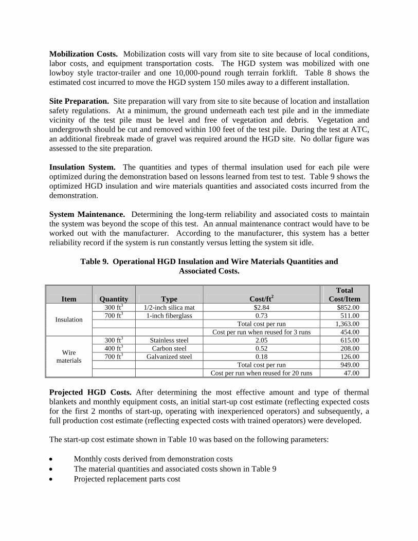
Mobilization Costs. Mobilization costs will vary from site to site because of local conditions, labor costs, and equipment transportation costs. The HGD system was mobilized with one lowboy style tractor-trailer and one 10,000-pound rough terrain forklift. Table 8 shows the estimated cost incurred to move the HGD system 150 miles away to a different installation. Site Preparation. Site preparation will vary from site to site because of location and installation safety regulations. At a minimum, the ground underneath each test pile and in the immediate vicinity of the test pile must be level and free of vegetation and debris. Vegetation and undergrowth should be cut and removed within 100 feet of the test pile. During the test at ATC, an additional firebreak made of gravel was required around the HGD site. No dollar figure was assessed to the site preparation. Insulation System. The quantities and types of thermal insulation used for each pile were optimized during the demonstration based on lessons learned from test to test. Table 9 shows the optimized HGD insulation and wire materials quantities and associated costs incurred from the demonstration. System Maintenance. Determining the long-term reliability and associated costs to maintain the system was beyond the scope of this test. An annual maintenance contract would have to be worked out with the manufacturer. According to the manufacturer, this system has a better reliability record if the system is run constantly versus letting the system sit idle.
Table 9. Operational HGD Insulation and Wire Materials Quantities and Associated Costs.
Item Quantity Type Cost/ft2 Total
Cost/Item 300 ft3 1/2-inch silica mat $2.84 $852.00 700 ft3 1-inch fiberglass 0.73 511.00
Total cost per run 1,363.00 Insulation
Cost per run when reused for 3 runs 454.00 300 ft3 Stainless steel 2.05 615.00 400 ft3 Carbon steel 0.52 208.00 700 ft3 Galvanized steel 0.18 126.00
Total cost per run 949.00
Wire materials
Cost per run when reused for 20 runs 47.00 Projected HGD Costs. After determining the most effective amount and type of thermal blankets and monthly equipment costs, an initial start-up cost estimate (reflecting expected costs for the first 2 months of start-up, operating with inexperienced operators) and subsequently, a full production cost estimate (reflecting expected costs with trained operators) were developed. The start-up cost estimate shown in Table 10 was based on the following parameters: • Monthly costs derived from demonstration costs • The material quantities and associated costs shown in Table 9 • Projected replacement parts cost
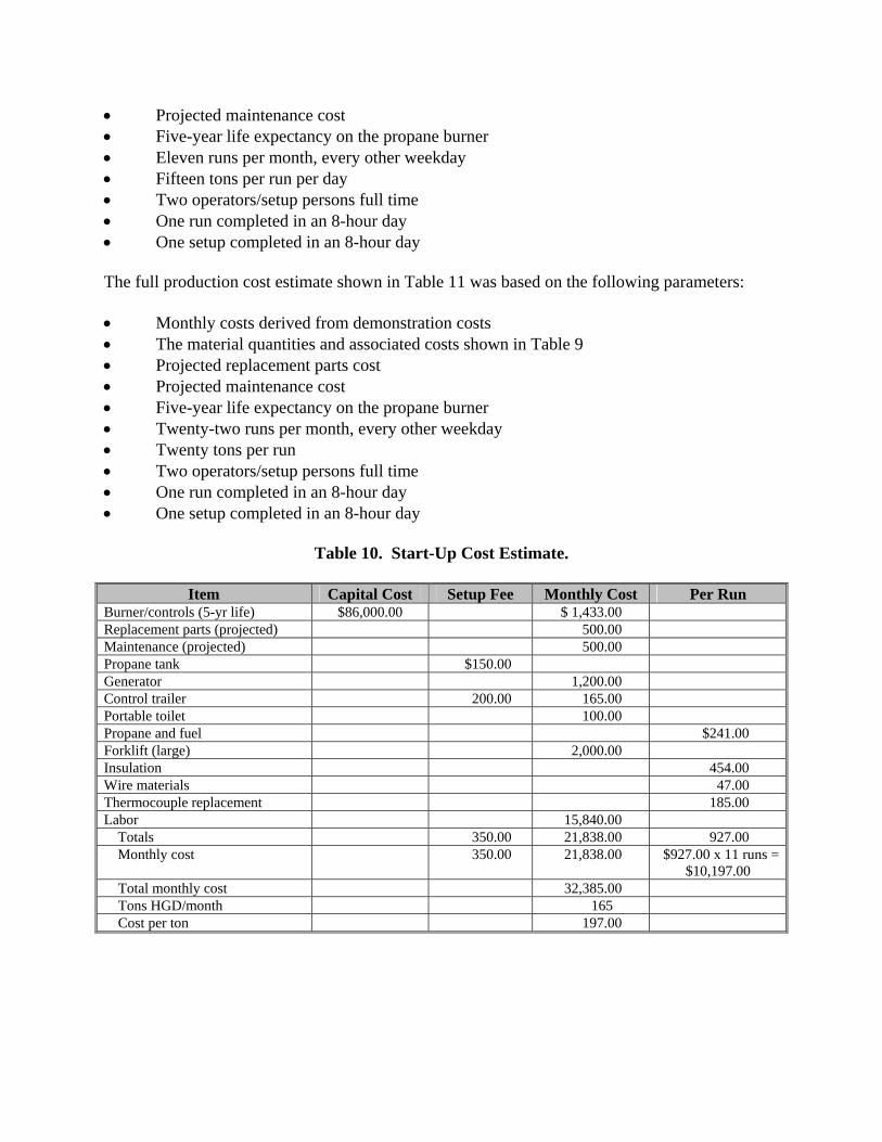
• Projected maintenance cost • Five-year life expectancy on the propane burner • Eleven runs per month, every other weekday • Fifteen tons per run per day • Two operators/setup persons full time • One run completed in an 8-hour day • One setup completed in an 8-hour day The full production cost estimate shown in Table 11 was based on the following parameters: • Monthly costs derived from demonstration costs • The material quantities and associated costs shown in Table 9 • Projected replacement parts cost • Projected maintenance cost • Five-year life expectancy on the propane burner • Twenty-two runs per month, every other weekday • Twenty tons per run • Two operators/setup persons full time • One run completed in an 8-hour day • One setup completed in an 8-hour day
Table 10. Start-Up Cost Estimate.
Item Capital Cost Setup Fee Monthly Cost Per Run Burner/controls (5-yr life) $86,000.00 $ 1,433.00 Replacement parts (projected) 500.00 Maintenance (projected) 500.00 Propane tank $150.00 Generator 1,200.00 Control trailer 200.00 165.00 Portable toilet 100.00 Propane and fuel $241.00 Forklift (large) 2,000.00 Insulation 454.00 Wire materials 47.00 Thermocouple replacement 185.00 Labor 15,840.00
Totals 350.00 21,838.00 927.00 Monthly cost 350.00 21,838.00 $927.00 x 11 runs =
$10,197.00 Total monthly cost 32,385.00 Tons HGD/month 165 Cost per ton 197.00

Table 11. Full Production Cost Estimate.
Item Capital Cost Setup Fee Monthly Cost Per Run Burner/controls $86,000.00 $1,433.00 Replacement parts 1,000.00 Maintenance 1,000.00 Propane tank $150.00 Generator 1,200.00 Control trailer 200.00 165.00 Portable toilet 135.00 Propane and fuel $241.00 Forklift (large) 2,000.00 Insulation 454.00 Wire materials 47.00 Thermocouple replacement 185.00 Labor 15,840.00
Totals 350.00 22,773.00 927.00 Monthly cost 350.00 22,773.00 20,394.00 Total monthly cost 43,517.00 Tons HGD/month 440 Cost per ton 99.00
Cost Comparisons to Other Types of HGD Technologies. The cost for the transportable HGD system in a blanket-on-pile configuration was compared with two comparable types of facilities for range scrap treatment described in these two reports: • A permanent fixed-facility HGD as reported in “Demonstration Results of Hot Gas
Decontamination for Explosives at Hawthorne Army Depot (Final).” [15] • A transportable HGD furnace as reported in “Validation Test Report for the
Transportable Hot-Gas Decontamination System Used to Support the Decontamination of Explosives contaminated Piping and Debris.” [10].
A comparison of the cost for the blanket-on-pile transportable HGD system was made versus the fixed facility using an HGD furnace and the transportable HGD furnace in this section. Refer to Section 5.7 of the HGD final report for a comparison of the technical components of the three technologies. The fixed facility and the transportable HGD furnace cost comparison data were based on the following parameters: • Decontamination of 15,000 tons of scrap • A 5-day, 8-hour per day work week with 22 work days per month for the fixed facility
and for the blanket-on-pile transportable HGD system • A 7-day, 24-hour per day work week for the transportable HGD furnace.
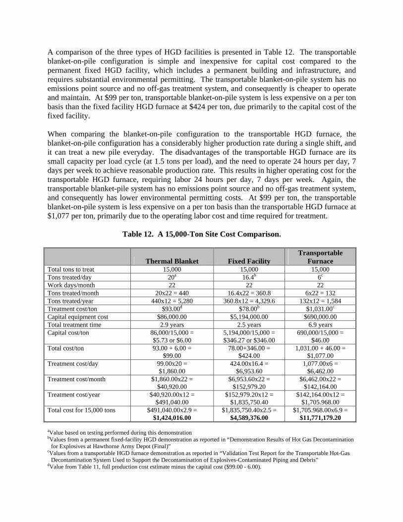
A comparison of the three types of HGD facilities is presented in Table 12. The transportable blanket-on-pile configuration is simple and inexpensive for capital cost compared to the permanent fixed HGD facility, which includes a permanent building and infrastructure, and requires substantial environmental permitting. The transportable blanket-on-pile system has no emissions point source and no off-gas treatment system, and consequently is cheaper to operate and maintain. At $99 per ton, transportable blanket-on-pile system is less expensive on a per ton basis than the fixed facility HGD furnace at $424 per ton, due primarily to the capital cost of the fixed facility. When comparing the blanket-on-pile configuration to the transportable HGD furnace, the blanket-on-pile configuration has a considerably higher production rate during a single shift, and it can treat a new pile everyday. The disadvantages of the transportable HGD furnace are its small capacity per load cycle (at 1.5 tons per load), and the need to operate 24 hours per day, 7 days per week to achieve reasonable production rate. This results in higher operating cost for the transportable HGD furnace, requiring labor 24 hours per day, 7 days per week. Again, the transportable blanket-pile system has no emissions point source and no off-gas treatment system, and consequently has lower environmental permitting costs. At $99 per ton, the transportable blanket-on-pile system is less expensive on a per ton basis than the transportable HGD furnace at $1,077 per ton, primarily due to the operating labor cost and time required for treatment.
Table 12. A 15,000-Ton Site Cost Comparison.
Thermal Blanket Fixed Facility Transportable
Furnace Total tons to treat 15,000 15,000 15,000 Tons treated/day 20a 16.4b 6c
Work days/month 22 22 22 Tons treated/month 20x22 = 440 16.4x22 = 360.8 6x22 = 132 Tons treated/year 440x12 = 5,280 360.8x12 = 4,329.6 132x12 = 1,584 Treatment cost/ton $93.00d $78.00b $1,031.00c Capital equipment cost $86,000.00 $5,194,000.00 $690,000.00 Total treatment time 2.9 years 2.5 years 6.9 years Capital cost/ton 86,000/15,000 =
$5.73 or $6.00 5,194,000/15,000 = $346.27 or $346.00
690,000/15,000 = $46.00
Total cost/ton 93.00 + 6.00 = $99.00
78.00+346.00 = $424.00
1,031.00 + 46.00 = $1,077.00
Treatment cost/day 99.00x20 = $1,860.00
424.00x16.4 = $6,953.60
1,077.00x6 = $6,462.00
Treatment cost/month $1,860.00x22 = $40,920.00
$6,953.60x22 = $152,979.20
$6,462.00x22 = $142,164.00
Treatment cost/year $40,920.00x12 = $491,040.00
$152,979.20x12 = $1,835,750.40
$142,164.00x12 = $1,705.968.00
Total cost for 15,000 tons $491,040.00x2.9 = $1,424,016.00
$1,835,750.40x2.5 = $4,589,376.00
$1,705.968.00x6.9 = $11,771,179.20
aValue based on testing performed during this demonstration bValues from a permanent fixed-facility HGD demonstration as reported in “Demonstration Results of Hot Gas Decontamination
for Explosives at Hawthorne Army Depot (Final)” cValues from a transportable HGD furnace demonstration as reported in “Validation Test Report for the Transportable Hot-Gas
Decontamination System Used to Support the Decontamination of Explosives-Contaminated Piping and Debris” dValue from Table 11, full production cost estimate minus the capital cost ($99.00 - 6.00).

This page left intentionally blank

6.0 IMPLEMENTATION ISSUES AND LESSONS LEARNED
6.1 GENERAL The transportable HGD was proven effective decontaminating range scrap as designed. During the demonstration, the system was proven and validated to process 14.5 tons in an 8-hour workday. An 8-hour workday is desirable for full-scale production to save cost of premium overtime. The system proved capable of processing 20 tons in an 11-hour day, but improving to the 8-hour day production rate is preferable for reducing the overall cost. There are several possible avenues to improve performance and increase production up to 20 tons per 8-hour day or higher. These include: • Oblong shape for pile along axis of burner rather than circular piles that have difficulty
distributing heat at 90o to the burner axis • Additional layers (more than one) of insulation • Use of two opposing smaller burners • Adding a heat distribution manifold under, through, or around the scrap pile 6.2 EQUIPMENT AND MATERIALS 6.2.1 Burner System While the system worked as planned, the ultimate goal is to increase production, which results in a decrease in cost. A heat distribution manifold would greatly increase the process efficiency and decrease the processing time and labor cost. The burner system would be more effective with a heat distribution manifold at the outlet to direct the heat to the outer reaches of the pile. The heat distribution manifold would be a stainless steel duct starting at the burner shroud with a manifold running under or around on the outside and branch ducts feeding heat to the other areas of the pile. This arrangement distributes heat evenly and quickly, thereby reducing heat-up time and operating cost. Another approach would be to use two smaller burners, which would inject heat from opposite ends of the pile. During project planning, the multiple burner approach received serious consideration but was not used to simplify the control system and reduce cost. The hot air and heat from the burner tended to bounce off the pile where it impacted and deflected straight upwards. This was observed in the pile during Test 1, when the insulation slipped during installation, creating a gap and allowing heat to escape through the insulation gap. As a result, the system did not effectively heat up the pile during Test 1.

The burner shroud was 6 to 8 feet short of the pile, too short to prevent hot air from deflecting off the pile. A heat distribution duct should be used to direct the heat into the pile to defeat the heat deflection phenomenon. The heat distribution duct should span from the end of the shroud through the pile. An I-beam was used in later tests to span from the top of the burner shroud horizontally to the pile. While only 10 or 12 inches wide, the purpose of the I-beam was to assist in deflecting heat downward toward the pile. The initial configuration of the pile and insulating system left the burner faceplate unprotected from the heat bouncing back from the pile to the burner. This subjected the burner faceplate to high heat in earlier tests. Upon inspection, no damage was observed to the faceplate metal, but the paint was burned off the faceplate. The faceplate was protected from the heat in later tests by placing insulation in front of it. In all tests, a large portion of the pile, possibly one-third, experienced very high temperatures up to 1,800oF and achieved the 5X condition of 1,000oF for 15 minutes. This indicates that a smaller pile size could meet the 5X condition with the existing burner/insulation system. 6.2.2 Thermocouples The thermocouples were K-type thermocouples with a maximum temperature limitation of 1,800oF. The thermocouple lead wires were rated at 1,200oF maximum. In early tests, three thermocouples failed at approximately 1,250oF, all at the hottest locations closest to the burner. It would appear that the lead wires were not sufficiently protected from the heat in these instances and too much lead wire was placed inside the insulation. In later tests, thermocouple leads were inserted through small penetration holes in the insulation and anchored to stainless steel wire mesh, thereby avoiding further thermocouple damage and failure. The insulation protected the lead wires, which were placed outside the insulation along their entire length. 6.2.3 Insulation Materials and Installation The insulating materials tended to present a nuisance and potential health hazard during installation and removal. Both silica-based and fiberglass insulations required the use of personal protective equipment (PPE) for installers. The silica-based insulation gave off a fibrous dust during the initial installation on the pile as well as after being exposed to high temperature. The Material Safety Data Sheets (MSDS) for the both the silica-based and fiberglass insulation indicate inhalation and skin contact hazards requiring appropriate PPE. Unshrunk Silmat, a silica-based high temperature insulation mat manufactured by Ametek, should not be used for this application. The unshrunk Silmat was too fragile for this application and extremely difficult to handle and install. The unshrunk Silmat ripped under its own weight when lifted, and when tearing gave off a dust of silica fibers into the air. This in turn was a respiratory and skin irritant health hazard for installers as listed in the MSDS. Shrunk Silmat, which is preshrunk at the factory, has higher handling strength and was far superior to unshrunk Silmat for this application.

When subjected to heat, the fiberglass insulation material discolored to a light brown color and was slightly burned looking. The manufacturer considers the discoloration normal. The starch binder material (about 1% or 1.5% by weight) chars to this color. The 1-inch thick fiberglass insulation is heavy and had to be installed with a forklift, while the 1/2-inch thick fiberglass is much lighter and easier to handle. Use of the Siltemp high temperature welding blanket fabric appeared redundant to the high temperature insulation, particularly when its cost is considered. It was purchased to protect the insulation in very hot areas. However, it did not exhibit any special ability to do so, above the high temperature insulation inherent capability. The temperature limitation of the Siltemp was 1,800oF, while the temperature limitation of the Silmat insulation was higher at 2,000oF, thereby eliminating the need for the Siltemp. The Siltemp alone does not have enough mass or weight to hold in hot air alone without the insulation. The thermal blankets are very heavy and cannot be moved when wet. The blankets should be kept dry, under tarps, when not in use. The blankets can be dried out in place on the pile by the burner if they get wet between operations and during removal from the pile. Heat Distribution. The burner system struggled to quickly meet temperature criteria in the outer reaches of the pile, specifically the lower areas left, right, and directly away from the burner. Trial and error during the test runs determined that a continuous uniform 1- or 2-inch gap around the perimeter of the back half of the pile along the ground away from the burner seems to direct the heat most uniformly to the farthest reaches of the pile. Spot venting caused cold spots and hot spots where hot gas funneled to the vent and circumvented closed-up areas. The left and right edges of the pile at the ground at 90o from the burner in each direction are the slowest to heat up to temperature, unless hot air is directed to these areas as described above. Test No. 4 was a successful test in terms of time, cost, and achieving successful decontamination temperature in approximately 7 hours (4 hours heat-up and 3 hours soak). An extra layer of 1-1/2 to 2 inches of insulation was used on many areas of the pile, speeding up the heat-up process time. Note that the 500oF for 2 hours time-temperature criteria was lower in Test No. 4, causing the decontamination process to fail in one area of the pile. Additionally, one of the test objectives was to determine the operational lower limit. Test No. 3 established that the explosives on the spiked coupons were removed with a decontamination temperature of 500oF for 3 hours. Test No. 4 established the lower limit. Conversely, Test No. 6 or No. 7 used less insulation (1/2 inch in many places) and the heat-up took noticeably longer, thereby increasing operator labor cost. One-half inch of high temperature insulation is not enough insulation to effectively heat-up the pile in a reasonable amount of time. A 1-1/2- to 2-inch layer of high temperature insulation is recommended to accelerate the process, increase processing rate, reduce labor cost and fuel consumption. As observed in Test No. 1, visible gaps in the insulation system resulted in significant heat loss and should be avoided. Due to the gap in the insulation, the pile was clearly losing a tremendous amount of heat through the gap. As a result, the maximum temperatures that the hottest thermocouples reached in Test No. 1 were approximately 950oF, which would have been much
higher without the gap. Gaps in the insulation will result in failure to meet time-temperature performance criteria. The insulation manufacturing industry has recognized the problems and health hazards associated with its current products and is actively addressing this situation with new product development. Several new products are currently on the market or under development that show promise to mitigate or relieve the health hazards and the need for PPE for handling the insulation. Some examples include: • Superwool, manufactured by Thermal Ceramics (thermalceramics.com). High
temperature calcium/ magnesium/silica-based mat blanket good to 2,012oF. • Silcosoft™, manufactured by BGF Industries, Inc. (bgf.com). High temperature, silica-
based mat blanket good to 2,000oF. BGF claims the product is nondusting, nonirritating, and a 9-micron diameter fiber nonrespirable, making handling safe and easy.
• Basalt Mat, manufactured by BGF Industries (bgf.com). High temperature mineral wool
(basalt fiber wool) mat blanket good to 1,500oF. Product is still under development as of 2002 but shows promise.
6.3 UTILITIES The failure of the electric power generator in Test No. 1 caused the entire test to fail. The lesson learned here is that if reliable fixed line power is available at range site, it is preferable to a less reliable electric power generator. 6.4 SECURITY Security of the scrap is critical after the scrap has been certified as inert and after it has been decontaminated. Live items or AEDA have been placed in scrap that has previously been certified as free from AEDA (or has been subject to low temperature thermal desorption). As a result, the scrap must be secured after it has been certified (or thermally treated). The concern is that a live round or flashable item could become inadvertently mixed into scrap that has already been inspected, certified, and decontaminated. The fundamental concept of the transportable HGD system in a pile configuration is to decontaminate a pre-existing pile of range scrap; however, the pile of scrap must be free from live rounds. Since a pile of scrap on a range is not a secure configuration even if inside an installation’s fence and gate, since a live item from an on-site range cleanup can be placed on a pile. In fact, inspection and certification of scrap already in a pre-existing pile will most likely be required, unless the pile has been tightly secured and there is assurance that no live rounds have been added. As a result of the above, HGD in either lockable wire basket containers or lockable dumpsters may have added value to the security/certification issue.

6.5 APPROACH TO REGULATORY COMPLIANCE AND ACCEPTANCE HGD is a possible solution to various disposal issues with respect to range residue. In this demonstration, transportable HGD uses are shown with respect to items containing surface contamination with trace quantities of explosives. By utilizing transportable HGD on the range, risks associated with residual contamination remain on the range. In analyzing the results of this demonstration, the most prominent regulatory issues associated with the implementation of transportable HGD are air emissions and the degree to which scrap must be decontaminated prior to disposal. In the implementation of transportable HGD, these issues are site-specific. Monitoring of site-specific representative composite samples of range scrap during test runs at future sites will be needed to provide data for that individual site, depending on the individual site’s federal, state, and local regulatory requirements. Each individual site must also determine the degree of decontamination needed. This will also be site-specific, depending on the items requiring decontamination and regulatory requirements.

This page left intentionally blank

39
7.0 REFERENCES 1. Department of Defense Directorate of Logistics Defense Material Reutilization Manual,
DoD 4160.21-M, Washington, DC, August 1997. 2. 40 Code of Federal Regulations (CFR) Parts 260 through 266 and Part 270,
Environmental Protection Agency (EPA) Munitions Rule. 3. Code of Maryland Regulations (COMAR) 26.11.02.10X, Sources Exempt from Permits
to Construct and Approvals. 4. Battelle Columbus Division. Pilot Plant Testing of the Hot Gas Building
Decontamination Process, U.S. Army Toxic and Hazardous Materials Agency (ATHAMA), Report No. AMXTH-TE-CR-87130, October 1987.
5. Arthur D. Little, Inc. Pilot Plant Testing of Caustic Spray HGD Building
Decontamination Process; Task Order 5, ATHAMA, Report No. AMXTH-TE-CR-87112, August 1987.
6. Roy F. Weston, Inc. Task Order 2 - Pilot Test of Hot Gas Decontamination of
Explosives Contaminated Equipment at Hawthorne Army Ammunition Plant, Hawthorne, Nevada, ATHAMA, Report No. CETHA-TE-CR-90036, July 1990.
7. The Tennessee Valley Authority Environmental Research Center, Demonstration Results
of Hot Gas Decontamination for Explosives at Hawthorne Army Depot (Final), Vol. I-IV, Hawthorne, Nevada, AEC, Aberdeen Proving Ground, Maryland, September 1995.
8. Parsons Engineering Science, Inc., Battelle Pacific Northwest Laboratories, Final
Technical Report: Field Demonstration of the Hot Gas Decontamination System, Report No. SFIM-AEC-ET-CR-95011, AEC, Aberdeen Proving Ground, Maryland, February 1995.
9. Roy F. Weston, Inc., Operations and Maintenance Manual for the Transportable Hot-Gas
Decontamination System Used to Support the Decontamination of Explosives Contaminated Piping and Debris, Vol. I-V, Contract No. DACA 31-91-D-0079, Task Order 12, AEC, Aberdeen Proving Ground, Maryland, September 1996.
10. Roy F. Weston, Inc., Validation Test Report for the Transportable Hot-Gas
Decontamination System Used to Support the Decontamination of Explosives contaminated Piping and Debris, Vol. I-III, Contract No. DACA 31-91-D-0079, Task Order 12, AEC, Aberdeen Proving Ground, Maryland, September 1996.
11. U.S. Army Aberdeen Test Center/Parsons. Final Demonstration Plan, Low-Cost
Decontamination of Explosives-Contaminated Range Scrap Using a Transportable Hot Gas Decontamination System, Aberdeen Proving Ground, Maryland, May 2001.

40
12. U.S. Army Aberdeen Test Center/Parsons. Final Draft Report, Low-Cost Decontamination of Explosives-Contaminated Range Scrap Using a Transportable Hot Gas Decontamination System, Aberdeen Proving Ground, Maryland, November 2002.
13. Cairlo, M., Harvey, P., Miller, S., Whitten, C. A Search for Explosives Sources in the
Western Boundary Study Area, Aberdeen Area, Aberdeen Proving Ground, Maryland. Draft OPSEC Control No. 2754-A-3, 7 August 1998.
14. SOP 385-2384, Conducting Magnetometer Sweeps, 6 May 1996. 15. RS Means, Construction Cost Data, Kinston, MA, 2001.
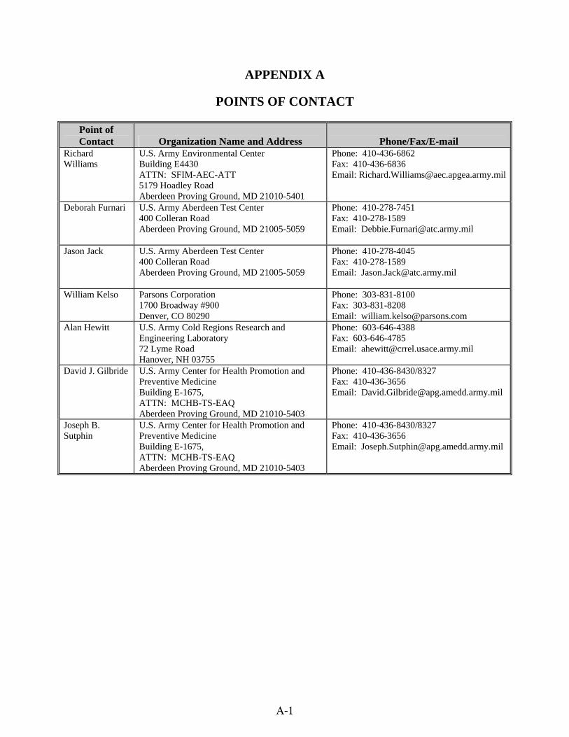
A-1
APPENDIX A
POINTS OF CONTACT
Point of Contact Organization Name and Address Phone/Fax/E-mail
Richard Williams
U.S. Army Environmental Center Building E4430 ATTN: SFIM-AEC-ATT 5179 Hoadley Road Aberdeen Proving Ground, MD 21010-5401
Phone: 410-436-6862 Fax: 410-436-6836 Email: [email protected]
Deborah Furnari
U.S. Army Aberdeen Test Center 400 Colleran Road Aberdeen Proving Ground, MD 21005-5059
Phone: 410-278-7451 Fax: 410-278-1589 Email: [email protected]
Jason Jack
U.S. Army Aberdeen Test Center 400 Colleran Road Aberdeen Proving Ground, MD 21005-5059
Phone: 410-278-4045 Fax: 410-278-1589 Email: [email protected]
William Kelso Parsons Corporation 1700 Broadway #900 Denver, CO 80290
Phone: 303-831-8100 Fax: 303-831-8208 Email: [email protected]
Alan Hewitt U.S. Army Cold Regions Research and Engineering Laboratory 72 Lyme Road Hanover, NH 03755
Phone: 603-646-4388 Fax: 603-646-4785 Email: [email protected]
David J. Gilbride U.S. Army Center for Health Promotion and Preventive Medicine Building E-1675, ATTN: MCHB-TS-EAQ Aberdeen Proving Ground, MD 21010-5403
Phone: 410-436-8430/8327 Fax: 410-436-3656 Email: [email protected]
Joseph B. Sutphin
U.S. Army Center for Health Promotion and Preventive Medicine Building E-1675, ATTN: MCHB-TS-EAQ Aberdeen Proving Ground, MD 21010-5403
Phone: 410-436-8430/8327 Fax: 410-436-3656 Email: [email protected]

EStcP Program office
901 north Stuart StreetSuite 303arlington, virginia 22203
(703) 696-2117 (Phone)(703) 696-2114 (fax)
e-mail: [email protected]