Embed Size (px)
Citation preview

Cost Optimization of Aircraft Structures
MARKUS KAUFMANN
Doctoral ThesisStockholm, Sweden 2009

TRITA-AVE 2009-83ISSN 1651-7660ISBN 978-91-7415-500-6
Kungliga Tekniska Hogskolan (KTH)Department of Aeronautical and Vehicle Engineering
SE-100 44 Stockholm, Sweden
Akademisk avhandling som med tillstand av Kungl Tekniska hogskolan framlagges tilloffentlig granskning for avlaggande av teknologie doktorsexamen i lattkonstruktionerfredagen den 11 december kl 10.15 i sal D2, Lindstedtsvagen 5, Kungliga Tekniskahogskolan, Stockholm.
© Markus Kaufmann, autumn 2009
Tryck: Universitetsservice US-AB

iii
Optimization is intrinsically tiedto our desire to excel, whether weare an athlete, artist or engineer.
Garret N. Vanderplaats [1]


v
Acknowledgments
The work presented in this thesis was carried out at the Department of Aero-nautical and Vehicle Engineering at KTH. Funding was provided by the EuropeanFramework Program 6, project ALCAS, AIP4-CT-2003-516092, and the SwedishNational Aeronautics Research Programme 4, project KEKS. The financial supportis gratefully acknowledged. Special thanks go to Dan Holm at Alfgam AB for theuse of Xopt and to Keith Garland and Andy Langridge at Galorath International forthe use of SEER. Finally, the collaboration with the people at Saab Aerostructuresis thankfully acknowledged.
”Why Sweden?” I’ve been asked many times during the last four years. Well, I’llnever forget my professor’s words while he showed me corrugated sandwich structuressix years ago. ”Plastic’s fantastic!” – Dan, the idea of designing exceptional thingswith an exceptional material was one of the reasons to follow your invitation andpursue a PhD under your guidance. You and my co-advisor Malin Akermo were aconstant source of enthusiasm, inspiration and motivation.
Another reason to return to Stockholm was the friendship with Peter & Frida,Ylva, Staffan, Joakim & Sofie, Chris & Camilla, Johan & Lotta and Mattu & Camilla(in order of appearance). Tack for alla oglombara stunder vi hade tillsammans! Awarm thank you to my friends and colleagues at KTH, particularly to my in-housebuddies Chris and Mio, and to Ylva (who critically supported my endeavors toimprove the local language).
My brother was the most frequent flyer between Zurich and Stockholm, andproofreader of so many things I’ve written during the last years. You’re a great guyand always welcome to your ”second” family!
I would further like to thank my parents for the endless support they providedduring all the years. Thank you for your belief in me!
But first and foremost, I would like to thank Anneke, whose love and supportmade this thesis possible. Soon a chapter of our life is over and I’m looking forwardto the continuation of our story – wherever it will be!
Markus Kaufmann
Stockholm in 2009


vii
Abstract
Composite structures can lower the weight of an airliner significantly. Due to the higherprocess complexity and the high material cost, however, the low weight often comes with asignificant increase in production cost. The application of cost-effective design strategies isone mean to meet this challenge.
In this thesis, a simplified form of direct operating cost is suggested as a comparativevalue that in combination with multidisciplinary optimization enables the evaluation of adesign solution in terms of cost and weight. The proposed cost optimization frameworktakes into account the manufacturing cost, the non-destructive testing cost and the lifetimefuel consumption based on the weight of the aircraft, thus using a simplified version of thedirect operating cost as the objective function. The manufacturing cost can be estimatedby means of different techniques. For the proposed optimization framework, feature-basedparametric cost models prove to be most suitable.
Paper A contains a parametric study in which a skin/stringer panel is optimized fora series of cost/weight ratios (weight penalties) and material configurations. The weightpenalty (defined as the specific lifetime fuel burn) is dependent on the fuel consumption ofthe aircraft, the fuel price and the viewpoint of the optimizer. It is concluded that the idealchoice of the design solution is neither low-cost nor low-weight but rather a combinationthereof.
Paper B proposes the inclusion of non-destructive testing cost in the design processof composite components, and the adjustment of the design strength of each laminateaccording to inspection parameters. Hence, the scan pitch of the ultrasonic testing isregarded as a variable, representing an index for the guaranteed material quality. It isshown that the cost for non-destructive testing can be lowered if the quality level of thelaminate is assigned and adjusted in an early design stage.
In Paper C and Paper D the parameters of the manufacturing processes are upgradedduring the cost optimization of the component. In Paper C, the framework is extended bythe cost-efficient adaptation of parameters in order to reflect the situation when machiningan aluminum component. For different weight penalties, the spar thickness and stringergeometry of the provided case study vary. In addition, another cutter is chosen with regardto the modified shape of the stringer. In Paper D, the methodology is extended to thedraping of composite fabrics, thus optimizing not only the stacking layup, but also thedraping strategy itself. As in the previous cases, the design alters for different settings ofthe weight penalty. In particular, one can see a distinct change in fiber layup between theminimum weight and the minimum cost solution.
Paper E summarizes the work proposed in Papers A-D and provides a case study ona C-spar component. Five material systems are used for this case study and comparedin terms of cost and weight. The case study shows the impact of the weight penalty, thematerial cost and the labor rate on the choice of the material system. For low weightpenalties, for example, the aluminum spar is the most cost-effective solution. For highweight penalties, the RTM system is favorable. The paper also discusses shortcomingswith the presented methodology and thereby opens up for future method developments.


Dissertation
This doctoral thesis is based on an introduction to the area of research and thefollowing appended papers:
Paper A
M. Kaufmann, D. Zenkert and P. Wennhage. Integrated cost/weight optimizationof aircraft structures. Accepted for publication in Structural and MultidisciplinaryOptimization, online version doi: 10.1007/s00158-009-0413-1.
Paper B
M. Kaufmann, D. Zenkert and C. Mattei. Cost optimization of composite aircraftstructures including variable laminate qualities. Composites Science and Technology,68; 2748-2754, 2008.
Paper C
M. Kaufmann, T. Czumanski and D. Zenkert. Manufacturing process adaptationfor integrated cost/weight optimisation of aircraft structures. Plastics, Rubber andComposites: Macromolecular Engineering, 38(2):162-166(5), 2009.
Paper D
M. Kaufmann, D. Zenkert and M. Akermo. Cost/weight optimization of compositeprepreg structures for best draping strategy. Accepted for publication in CompositesPart A: Applied Science and Manufacturing, 2009.
Paper E
M. Kaufmann, D. Zenkert and M. Akermo. Material selection for aircraft componentsbased on cost optimization. Manuscript submitted to Journal of Aircraft (DesignForum).
ix

x
Parts of this thesis have also been presented as follows:
M. Kaufmann, D. Zenkert and P. Wennhage. Integrated cost/weight optimizationof composite skin/stringer elements. In Proceedings of the 16th InternationalConference on Composite Materials (ICCM-16), Kyoto (Japan), 2007.
M. Kaufmann, T. Czumanski and D. Zenkert. Manufacturing Process Adaptationfor the Integrated Cost/Weight Optimization of Aircraft Structures. In Proceedingsof the 13th European Conference on Composite Materials (ECCM-13), Stockholm(Sweden), 2008.
M. Kaufmann and D. Zenkert. Cost Optimization of Composite Aircraft Structures.In Proceedings of the 22nd Nordic Seminar on Computational Mechanics (NSCM22),Aalborg (Denmark), 2009.
M. Kaufmann. Integrated Cost/Weight Optimization of Composite Aircraft Struc-tures. In Proceedings of the 9th Swedish Production Symposium (SPS’09), Gothen-burg (Sweden), 2009.

Contents
I Introduction 1
1 Background 3
2 Structural Design of Aircrafts 72.1 Design Phases . . . . . . . . . . . . . . . . . . . . . . . . . . . . . . . 72.2 System Integration . . . . . . . . . . . . . . . . . . . . . . . . . . . . 82.3 Design of Composite Structures . . . . . . . . . . . . . . . . . . . . . 102.4 Constraints and Allowables . . . . . . . . . . . . . . . . . . . . . . . 112.5 Non-Destructive Testing . . . . . . . . . . . . . . . . . . . . . . . . . 12
3 Design Optimization 153.1 Multiobjective Optimization . . . . . . . . . . . . . . . . . . . . . . . 173.2 Weight Optimization . . . . . . . . . . . . . . . . . . . . . . . . . . . 193.3 Integrated Cost/Weight Optimization . . . . . . . . . . . . . . . . . 19
4 Cost and Cost Estimation 234.1 Life-Cycle Cost and Direct Operating Cost . . . . . . . . . . . . . . 234.2 Design and Cost . . . . . . . . . . . . . . . . . . . . . . . . . . . . . 244.3 Estimation of Manufacturing Cost . . . . . . . . . . . . . . . . . . . 254.4 Estimation of Non-Destructive Testing Cost . . . . . . . . . . . . . . 27
5 Forming of Composites 295.1 Models for Composite Forming . . . . . . . . . . . . . . . . . . . . . 295.2 Composite Modeler . . . . . . . . . . . . . . . . . . . . . . . . . . . . 34
6 Cost Optimization Framework 37
7 Conclusion 41
8 Future Work 43
Bibliography 45
xi

xii M. Kaufmann
II Appended papers 53

Part I
Introduction
1


1 Background
”In a switch that could make Airbus’s next jetliner more competitive with rival BoeingCo.’s new 787 Dreamliner, the European plane maker plans to build the frame ofits planned A350 model from advanced composite materials instead of metal. Thelighter structure – similar to that of the Boeing plane – reduces fuel consumption,increases a plane’s range and reduces wear on key parts such as landing gear. Theshift also cuts the need for costly maintenance inspections. [. . . ]”
This article, published by the Wall Street Journal on Saturday, September 15,2007, summarizes the achievements in the field of aerospace structures over the lastcouple of years. Material configurations are undergoing a change from metals tocomposites, thus lowering the structural weight and avoiding fatigue and corrosion.No cost aspects, however, are mentioned in the article. How much more does thecomposite version cost compared to the metallic baseline? And how far could anincrease in manufacturing cost be motivated by the saving of weight?
Figure 1.1: Airbus A350
3
4 M. Kaufmann
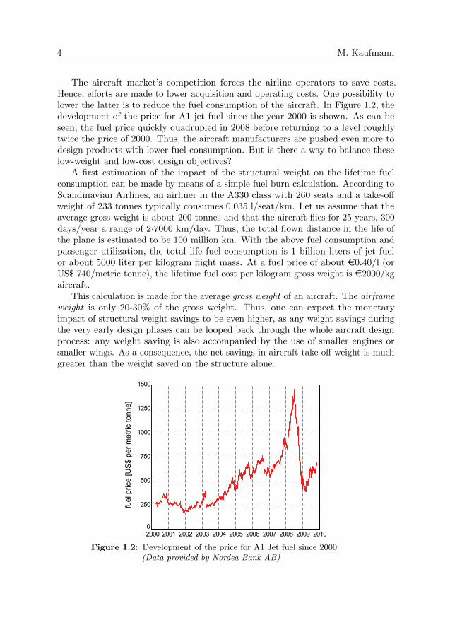
The aircraft market’s competition forces the airline operators to save costs.Hence, efforts are made to lower acquisition and operating costs. One possibility tolower the latter is to reduce the fuel consumption of the aircraft. In Figure 1.2, thedevelopment of the price for A1 jet fuel since the year 2000 is shown. As can beseen, the fuel price quickly quadrupled in 2008 before returning to a level roughlytwice the price of 2000. Thus, the aircraft manufacturers are pushed even more todesign products with lower fuel consumption. But is there a way to balance theselow-weight and low-cost design objectives?
A first estimation of the impact of the structural weight on the lifetime fuelconsumption can be made by means of a simple fuel burn calculation. According toScandinavian Airlines, an airliner in the A330 class with 260 seats and a take-offweight of 233 tonnes typically consumes 0.035 l/seat/km. Let us assume that theaverage gross weight is about 200 tonnes and that the aircraft flies for 25 years, 300days/year a range of 2·7000 km/day. Thus, the total flown distance in the life ofthe plane is estimated to be 100 million km. With the above fuel consumption andpassenger utilization, the total life fuel consumption is 1 billion liters of jet fuelor about 5000 liter per kilogram flight mass. At a fuel price of about e0.40/l (orUS$ 740/metric tonne), the lifetime fuel cost per kilogram gross weight is e2000/kgaircraft.
This calculation is made for the average gross weight of an aircraft. The airframeweight is only 20-30% of the gross weight. Thus, one can expect the monetaryimpact of structural weight savings to be even higher, as any weight savings duringthe very early design phases can be looped back through the whole aircraft designprocess: any weight saving is also accompanied by the use of smaller engines orsmaller wings. As a consequence, the net savings in aircraft take-off weight is muchgreater than the weight saved on the structure alone.
2000 2001 2002 2003 2004 2005 2006 2007 2008 2009 20100
250
500
750
1000
1250
1500
nne]
ot cirtem rep $
SU[ ecirp l euf
Figure 1.2: Development of the price for A1 Jet fuel since 2000(Data provided by Nordea Bank AB)

Introduction 5
We could change the design objectives and consider a possible increase in revenueinstead of the fuel saving. Assuming an aircraft with one transatlantic return tripa day, 300 days a year for 25 years and a ticket price of e500 would result in arevenue of e3’750’000 per chair. If we further assume that 125 kg weight saving isneeded per additional passenger, a total of e30’000 could potentially be earned perkilogram structure.
A lot of work has been performed in the field of pure weight optimization. Theapplication of a lifetime cost per kilogram airframe structure, however, provides uswith a tool to include cost and weight in the optimization of aircraft structures.
Gutowski et al. described the composite’s drawbacks already back in 1991 [2].The cost of the composite raw material is roughly ten times the cost of aluminum.The material cost, however, reflects only a small part of the total cost of the finalproduct. First, the labor cost to manufacture a composite component is muchhigher than for a comparable metal part. Second, the production of compositecomponents brings a need for an extensive quality management and rigorous non-destructive testing. Third, the increased design complexity comes with an increasein development cost.
These risks were also identified by Rais-Rohani and Dean [3]. According tothem, the high material, fabrication and tooling costs may make the use of high-performance materials cost-ineffective. Thus, the costs of raw materials, tooling,fabrication, assembly, scrap, repair, certification and environmental factors should beincluded in the design of composite structures. Sobieszczanski-Sobieski and Haftkaobserved an absence of cost optimization frameworks for composite components [4].Soutis pointed out that early composite designs were ”replicas of those that employedmetallic materials” from the 40s, as most composite parts were manufactured withexpensive hand-laid carbon epoxy prepregs using quasi-isotropic stacking sequences.According to the authors ”the high material cost and man-hour-intensive laminateproduction jeopardized their acceptance” [5].
In this thesis, a framework for the cost optimization of aircraft structures isproposed. In Chapter 2, the three phases in the structural design of aircrafts arepresented. Chapter 3 introduces the field of multidisciplinary design optimization.By means of a literature survey, existing cost/weight optimization frameworksand their differences are presented. Chapter 4 deals with the definition of directoperating cost and the estimation of manufacturing cost, followed by an overviewof composite forming in Chapter 5. Finally, an introduction to the proposedoptimization framework and the appended papers is given, followed by a shortdiscussion and the identification of possible future work.

2 Structural Design of Aircrafts
2.1 Design Phases
The design of aircrafts can roughly be divided into three design phases, the conceptualdesign phase, the preliminary design phase and the detail design phase. They allhave a distinctive multidisciplinary character, the result being a tradeoff made byall stakeholders.
Conceptual Design
In the conceptual design phase, numerous design alternatives are compared andevaluated, based on cost/weight/passenger/range tradeoff studies. The result is aninitial aerodynamics and propulsion concept, including overall dimensions, weightsand global loads.
Preliminary Design
In the preliminary design phase, a global finite element model is built up from whichlocal loads and loading conditions are derived. An illustration of typical loads onan airliner is given in Figure 2.1. As can be seen, aeroelastic loads such as tensile,compressive and torsional loads in wing, fuselage and empennage represent only afraction of the load cases the structural engineers have to consider. Other loadsarise from the cabin pressure (hoop stress), bird strike or impact loads on the tail.Very high local stresses can be found in the landing gear ribs, the sidestay fittingsand the pylon structure.
The task of the structural engineers is the design of the inner structure of theaircraft. The design is constrained by the aerodynamic configuration. It has towithstand all loads and should be as light as possible. Different levels of detail areinvestigated in the preliminary design phase, see Figure 2.2. First, the structuralarrangement of the major parts, such as ribs and spars in the wing and lap joints andbutt joints in the fuselage are defined. Then, the structure is designed on a panellevel. The strength and stiffness of the structural members are defined and verifiedby means of finite element models, while changes in the configuration (e.g. stiffenerdistance, flange type, rib stiffeners, etc.) are still possible. According to Assler [6],the design process is influenced by a variety of factors at this stage. Examples are
7

8 M. Kaufmann
Bending
Bending andTorsion
Impact
Shear(transverse shear and torsion)
Longit. Compression (bending)Corrosion ResistanceHigh Local LoadsHoop Tension
Impact
Impact
ShearStress
Longit. Tension(bending)
Upper skin:Compression
Impact
Lower skin:Tension
Figure 2.1: Typical local loads on an airliner (by courtesy of H. Assler,Airbus Deutschland GmbH)
- Airworthiness regulations- Environmental considerations- General aircraft requirements (operational profile, maintenance, etc.)- Specific requirements for structural details- Available materials and technologies- Manufacturing capacities and capabilities- Non-destructive testing and investigation capabilities- Design cost
Detail Design
In the detail design phase, the structure is analyzed by means of high-fidelitymodels, and the fabrication, tooling and assembly processes are defined. The resultis a detailed work breakdown structure including all structural parts, mounting,bolts and rivets, clips, doors, brackets, etc. Each part has to fulfill its particularrequirements, based on structural failure, fatigue, corrosion resistance, lightningstrike, sealing, conduction, maintenance or testing.
2.2 System Integration
As the development of a new aircraft type involves great cost and – in turn – a greatfinancial risk, aircrafts are not designed, fabricated and assembled by one singlemanufacturer anymore; the latter have been replaced by consortiums of systemintegrators and suppliers. In Figure 2.3, the supply hierarchy in the commercialaerospace industry is shown.
On top of the supply pyramid, a system integrator (e.g. Boeing or Airbus) isresponsible for the coordination, the overall design and the final assembly of the

Introduction 9
Butt Joint
Aircraft
Structural Detail Fuselage Panel
Fuselage Section
Stringer
LapJoint
SkinClip
Frame
Figure 2.2: Levels of detail (by courtesy of H. Assler,Airbus Deutschland GmbH)
aircraft. In a subordinate position, other members of the consortium take part inthe development of sub-systems (such as wing structures), its manufacturing, sub-assembly and delivery. Further down in the hierarchy are equipment and componentsuppliers. They do not take part in the design process and are restricted to themanufacturing and delivery of components. Estimated profit margins are the highestin the top position of the pyramid and – according to Johansen et al. [7] – the higherthe position in the hierarchy, the greater the risk for that company in the overallproject.
The embedding of a sub system supplier (e.g. Saab, Bombardier or Alenia)occurs in the conceptual design phase, sometimes already within pre-development orresearch projects. The benefits of this approach are the early exchange of knowledgeand experience, and a good integration of the otherwise widespread design teams.As the risks are shared, each of the partners are under pressure to continuouslyincrease the efficiency in terms of low cost, low weight and producibility. Themain drawbacks mentioned in [7] are communication problems across the companyborders, such as cultural differences, hierarchical misunderstandings and delayed
SI
Sub system
Equipment supplier
Component supplier
System integrator
Figure 2.3: Supply hierarchy in the commercial aerospace industry

10 M. Kaufmann
information flows. Further mentioned is the need for an extensive product lifecyclemanagement database (PLM). In the case of the A380, the PLM is used by morethan 5000 engineers and contains more than 3000 CAD drawings of about 150’000parts.
2.3 Design of Composite Structures
As mentioned, the fuel consumption stands for a considerable part of the operatingcost of an airliner. As shown in Jacobsen [8], the fuel cost can be reduced bydeveloping more efficient engines, by minimizing the aerodynamic drag, by optimizingthe flight trajectory of the aircraft and by reducing its mass. The latter was the mainmotive to change from metals to composite materials, and the portion of compositematerials of the total structural weight is continuously increasing in commercialairliners, see Figure 2.4.
10
15
20
5
40
25
35
30
45
0201020052000199519901985198019751970
Com
posi
te S
truct
ural
Wei
ght[
%]
A300A310-200
A320 A340-300
A400M
A340-600
A380
A350
Figure 2.4: Portion of composite materials in Airbus aircrafts(by courtesy of H. Assler, Airbus Deutschland GmbH)
The first application of composites to commercial aircrafts were radar domesin 1940. Since then, composite materials have increasingly replaced their metalliccounterparts. In 1975, NASA developed a series of composite parts for researchpurposes, and the elevators of the B727 and B737 and the vertical fin of the DC10were redesigned. Secondary structures (e.g. the leading edge, trailing edge, flaps,ailerons and rudder) were made of carbon fibers in the Boeing 777, and with thecenter wing box of the A380, composites were used also for primary (load-carrying)structures. The latter enabled weight savings of 1500 kg compared to the aluminumbaseline, see Marsh [9].
A comparison of the specific strengths and stiffnesses is presented in Figure 2.5.As can be seen, the specific strength of carbon fiber reinforced plastic is much higherthan for aluminum or titanium, whereas the specific moduli are approximately the

Introduction 11
same. A composite component that is designed for stiffness will therefore have ahigher safety factor against material failure than its metallic counterpart. Thischaracteristic accounts for the good fatigue behavior of composites, cutting downthe maintenance cost for the airlines. Another advantage is the possibility to tailorcomposites specifically to a desired function. This is done by either adjusting thefiber angle distribution or by unifying the geometry and thus reducing the numberof parts.
Specificstrength
σ/ρ
Specific stiffness E/ρ
0
50
100
150
200
250
300
0 5 10 15 20 25 30 35 40
Glass(QI)
Carbon (QI)
Titanium
Magnesium
Steel
Aluminum
Figure 2.5: Specific strengths and stiffnesses of different metals and al-loys, quasi-isotropic glass fiber reinforced plastic (Glass/QI)and quasi-isotropic carbon fiber reinforced plastic (Car-bon/QI)
2.4 Constraints and Allowables
The structure has to withstand anticipated external loads. For composites loaded intension, material failure might be the limiting constraint. For composites loadedin compression, material failure and stability concerns form the topology of thestructure. The situations under which the integrity of the structure needs to beproved are described in regulations published by the aviation authorities. Structuralconstraints, for example, are based on the airworthiness requirements, defined inJAR 25.613 Material Strength Properties and Design Values. This document isreleased by the Joint Aviation Authorities1, a European body representing the civilaviation regulatory authorities of a number of European states. Similar regulationsexist also in the United States (FAR). Therefore it is often referred to the FAR/JARregulations.
The determination of an allowable stress and strain limit is based on statisticalevaluation of specimen tests. A typical design strength, for instance, is the stresslevel where at least 90% of the population pass with a confidence of 95%. These
1http://www.jaat.eu

12 M. Kaufmann
tests have to be performed for filled or unfilled holes, as stress concentrations aroundfastener and bolt holes can be the cause for material failure. The test phase caninclude up to 4000 coupons to generate complete data for a certification program,see Niu [10].
A composite laminate can fail by different modes, e.g. by fiber failure, microbuck-ling, matrix failure or fiber/matrix debonding. Other effects are delaminations dueto pull-off loads, free-edge effects, poisson’s ratio mismatch or compressive buckling.Therefore, most engineers (and aeronautical engineers in particular) tend to userather conservative failure criteria.
Unlike metal structures, composite structures are limited by strain and not bystress concerns. The strain limits of composite laminates are only indirectly relatedto the strain levels of the matrix or the fibers; it is rather a design strain based oncoupon tests. One of the limiting load cases of coupon tests is the compression afterimpact test, simulating prior damage from tool drops and runway debris. There,the remaining compressive failure strain of a damaged composite panel is evaluated.Typically, values around 0.4% are obtained which is much lower than for unnotchedcoupons.
Albeit not being the most elaborate failure theory, the maximum strain criterionis still widely used in the aerospace industry. The maximum strain criterion is givenas three independent sub-criteria
ε1,c < ε1 < ε1,t
ε2,c < ε2 < ε2,t and (2.1)
|γ12| < γ12.
The indices c and t denote compression and tension, respectively; 1 and 2 denote theply’s longitudinal and transversal direction, andˆdenotes the allowable strain value.
Apart from material failure, the design of composite laminates is governedby a series of other rules. Examples given are the requirement for symmetricalstacking, a minimum amount of 10% of each ply angle, or the location of fiber splits.Aircraft engineers maintain a stacking sequence consisting of 0◦, 90◦ and ±45◦ plies.Although there exist stacking sequences that allow a significant weight reduction,certification issues prevent their use yet.
2.5 Non-Destructive Testing
The Federal Aviation Administration’s regulations of airworthiness require thequality assurance of each assembled part. Unlike metallic structures, compositeparts are fabricated in-situ and the grade of these structures is highly dependent onprocess robustness and workmen skills. Typical manufacturing generated defects incomposites are voids, porosity, fiber misalignment, wrinkling, poor cure, resin-rich orresin-poor areas, forgotten release papers and low-quality adhesive bonds. Therefore,each composite part undergoes rigorous non-destructive testing (NDT) prior to theassembly.

Introduction 13
For metallic and composite aircraft structures, NDT is also part of the damagetolerance concept. Micro-cracks are basically tolerated under the condition thatthe airliner is regularly checked for structural integrity (continuous monitoring andsufficiently slow growth of cracks). In so-called D checks, complete overhauls atsix to ten years intervals, the paint is removed and cracks or delaminations aresought. Apart from these regular checks, the integrity is also tested after bird strikes,hard landings or similar incidents. All these inspections are very costly due to thedowntime of the aircraft.
Ultrasonic Methods
Due to the nature of composite structures, flaws can occur in monolithic structures(porosity, delamination, cracks), the adhesive layers (debondings), or sandwichcores (density irregularities, cracks). While flaws in the outer skin can be detectedwith single-sided access, the underlaying defects often need through-transmissionscanning. Thick structures are generally more difficult to test than thin structures.
The most common method for the inspection of aircraft structures is ultrasonictesting (UT). There, a transducer is passed over the area being tested. Ultrasonicwaves penetrate the structure, while the receiver records the reflected (pulse-echomode) or the transmitted (through-transmission mode) sound waves, see Figure2.6. The screen on the diagnostic machine will show these results in the form ofamplitude and pulse readings, as well as the time of flight.
Time
Amplitude
Time
Amplitude
Transmitter
Receiver
Receiver
Flaw
Transmitter
Figure 2.6: Ultrasonic test setup in through-transmission mode [11]
The presentation of the amplitude of the wave as a function of time (the so-calledA-scan) is sufficient for manual detection of flaws. Scanning along a given routeleads to the B-scan presentation with the in-depth position of the flaw as a functionof scan distance and time of flight. The C-scan in turn represents an areal defectimage of the scanned part by scanning a 2D-pattern, while the D-scan combines thein-depth information of the B-scan with the C-scan. In Figure 2.7, the procedureto obtain a C-scan is shown. The density of the scan pattern (separated by thedistance later referred to as the scan pitch) determines the size of the detectableflaws.

14 M. Kaufmann
The advantage of UT is the high sensitivity, permitting detection of extremelysmall flaws. The penetrating power of UT is higher than for other methods, thusallowing detection of flaws deeper in the part. Unfortunately, damping effects oflocal inhomogeneities of composite structures (e.g. due to stacked prepregs) reducethe reflected energy significantly. Thus, the resolution of a C-scan is very muchdependent on the material system, the porosity level and the thickness.
Thick structures are difficult to inspect due to high damping characteristics andhigh structural noise. While air-coupled ultrasonic is possible in principle, this isrestricted to through-transmission mode. For pulse-echo testing, improvements arestill necessary, and water is therefore still common as the coupling medium betweenthe probe and the specimen.
Top View
Side View
Test Piece Defect
C-Scan Presentation
ScanPattern
Figure 2.7: Presentation of ultrasonic scan results as a C-scan [11]
Referring to the literature, the design of composite structures has not beeninfluenced by NDT aspects. In order to capture the full life cycle of a compositecomponent, however, NDT should play a role in an early design phase. Therefore, amethodology was developed that included the parameters of the in-production andin-service testing in the design process. Hence, the scan distance of the ultrasonicC-scan was introduced as a variable in the design optimization. In a feature-basedmodel, the NDT cost was calculated from the scan distance (the scan pitch). Further,the design allowables of the laminate were adapted, since the scan pitch had a directinfluence on the detectable flaw size. This methodology is presented in Paper B.

3 Design Optimization
Product design is a process where ideas are generated and screened, and conceptsare formulated, rephrased and rejected. This solution-finding process is iterativeand – in a wider sense – an optimization process. The former methods of trial andtesting, however, have been replaced more and more by abstract models. In thefield of aeronautics, such models can include flow models, cost models, structuralmodels, models of the material properties, or dynamic flight models. Often, severalmodels from different disciplines are necessary in order to represent the behavior andcharacteristics accurately enough. Most of the costs of the final product are definedin the conceptual design phase, and to neglect relevant design aspects in this phasewould be disadvantageous. Hence, the goal of concurrent aerospace engineering is togather knowledge from different disciplines by involving a multidisciplinary groupof engineers in the design process. Examples of involved areas are fluid mechanics,statics and dynamics (engineering mechanics), mathematics, electrotechnology,propulsion, control engineering, aircraft structures, materials science, productionengineering, aeroelasticity, avionics, risk and reliability, or noise control.
In recent years, attempts have been made to perform these design tasks simul-taneously rather than sequentially. However, difficulties were encountered relatedto the large amount of data that had to be shared, as well as cultural and commu-nicative problems between members of different fields or with different backgrounds.Another obstacle is often given by the company’s hierarchy: the information flow isnot provided, hierarchical structures do not promote concurrent engineering anddifferent departments are separated and distributed spatially.
One approach to incorporate the different disciplines in aircraft design into anautomated design environment is the use of multidisciplinary design optimization(MDO). As shown in Figure 3.1, an MDO framework combines relevant designdisciplines and runs the analysis tools simultaneously. Feedback is given to an opti-mization algorithm that calculates a new design solution by means of mathematicalprogramming or stochastic search methods, and provides inputs for the next roundof evaluation. These steps are repeated until the objective function, e.g. the weightof the part, is judged to be sufficiently minimized.
For an overview on MDO applications in the field of aerospace, it is referred tothe review article written by Sobieszczanski-Sobieski and Haftka [4]. They concludedthat most of the literature on multidisciplinary optimization covers the interaction
15

16 M. Kaufmann
Analysis n
Optimumreached?
optimization: findnew parameters
Initial parametricmodel
Post-processoptimum model
Form objective functionand constraints
Update parametricmodel
Analysis 1 Analysis 2
Figure 3.1: Multidisciplinary design optimization
between aerodynamics and structures (see Raymer [12] and Bartholomew [13]) orshape parametrization techniques (see Samareh [14]).
Multidisciplinary design optimization frameworks are continuously being devel-oped, see Samareh and Bhatia [15] and Townsend et al. [16]. For implementationslike NASA’s FIDO1 project, requirements like an intuitive user interface, handlingof a large problem size and support of collaborative design aspects were important.Salas and Townsend [17] described the requirements of such frameworks in detail.
A short review on cost considerations in multidisciplinary aircraft design was givenby Rais-Rohani and Dean [3]. In 1996, they proposed that costs of raw materials,tooling, fabrication, assembly, scrap, repair, certification and environmental factorsshould be included in the design of composite structures. They motivated theirreflection with former studies on the weight-to-cost relation of structures made ofadvanced materials which showed that the high material, fabrication and toolingcosts may make the use of high performance materials cost-ineffective. Accordingto that article, material and fabrication costs of composite structures are the keydrivers and of comparable importance as the assembly and maintenance costs ofmetal structures.
1Framework for Interdisciplinary Design Optimization

Introduction 17
3.1 Multiobjective Optimization
The multiobjective optimization framework proposed in this work contains theoptimization of different, often contradictive goals, such as low-cost and low-weight.Several ways to capture multiobjective design problems exist, see Marler andArora [18]. Two or more objectives should lead to an optimal geometry. Therefore,they have to be incorporated mathematically into one objective function F . Themultiobjective design problem is given as
min F (x) =
f1(x)f2(x)
...fn(x)
, n ≥ 2
subject to h(x) = 0, (3.1)
g(x) ≤ 0,x ≤ x ≤ x.
In our case, f1 and f2 represent the cost and the weight of a composite aircraftpart. Stability and failure criteria are represented by the inequality constraint g(x),whereas x and x are lower and upper limits of the variable vector x. An equalityconstraint h(x) is optional and not used throughout this work.
Goal Programming
One approach to solve the problem above is referred to as goal programming. Goalprogramming uses one of the objectives as the objective function, whereas uppervalues (goals) are set for the other objectives. For example, one could implement acost goal by setting an upper cost limit as a constraint to the optimization problem.This problem can be formulated as
min weight of a composite element
subject to - prescribed load case (3.2)
- maximum manufacturing cost.
On the other hand, one could do the reverse and optimize for cost only, while aimingfor a prescribed structural performance (weight goal). This is given as
min cost of a composite element
subject to - prescribed load case (3.3)
- maximum weight.
Both formulations have the drawback that the target cost or the target weight hasto be defined in advanced; being a one-shot technique, the goal has a great influenceon the optimal solution, and a poor formulation could lead to inferior designs.

18 M. Kaufmann
Multilevel Programming
Sometimes, the objectives can be ordered hierarchically in terms of importance.Hence, a top level objective function is defined and the set of points that minimizethis first level objective is sought. In a second step, the set is reduced to the pointsthat minimize the second level objective, and the method proceeds until the lowestlevel objective has been minimized. An example for multilevel optimization ofaircraft structures is given by Gantois and Morris [19].
This work, however, deals with the tradeoff behavior of a combined cost/weightoptimization. It is then not possible to order the two objectives, as they are on thesame level and cannot be separated hierarchically. Thus, first weight, then cost orfirst cost, then weight approaches would not make sense here.
Pareto Optimality
A topic closely related to multiobjective optimization is Pareto optimality. Imaginea full search exploration of all possible designs of a structural part, e.g. the pointsgiven in Figure 3.2. Each design solution is represented by a variable set x, amanufacturing cost f1 and a weight f2. The points that constitute combinations oflowest cost and lowest weight are marked with cross symbols; they are called Paretopoints.
A Pareto point is a point in the design space for which there is (a) no possibledesign solution with a lower weight and the same manufacturing cost or (b) nopossible design with the same weight and a lower manufacturing cost. The curve thatconnects all Pareto points is called the Pareto frontier. The Pareto frontier is of greatimportance in multiobjective optimization, as it represents the tradeoff behaviorof the two objectives. A lot of optimization algorithms deal with the generationof a complete Pareto frontier, thus providing a choice of possible solutions to theoptimization problem. Two classes of optimization algorithms developed to performthis particular task are the Homotopy Techniques, see Watson and Haftka [20], andthe Normal-Boundary Intersection, see Das and Dennis [21] and Huang et al. [22].
Cost
Wei
ght
X
X
X
XXXX
Figure 3.2: Design solutions, the corresponding Pareto points x andthe Pareto frontier –.

Introduction 19
Minimizing Weighted Sums
More promising is an approach called weighted sums where two or more objectivesare incorporated into one objective function and weighted by predefined parametersαi. These parameters represent the tradeoff between the objectives and result in aone-shot design solution. By varying αi, however, a range of solutions with differentcost/weight tradeoffs can be obtained. The objective function is given as
F (x) =n∑
i=1αifi(x), αi > 0, i = 1, 2, . . . , n. (3.4)
The approach of minimizing weighted sums is criticized by Das and Dennis [23],as the generation of evenly distributed Pareto points fails. However, in the case ofa combined cost/weight optimization, one would use the parameters to establisha relationship between the manufacturing cost and the structural weight, and thegeneration of a Pareto frontier is not necessary. This approach is described in detailbelow, where this cost/weight relationship is called weight penalty, representing the”lifetime fuel burn cost per unit structural mass”.
3.2 Weight Optimization
A lot of work has been done within the field of weight optimization. Representatively,the work of Kang and Kim [24] is mentioned, in which skin/stringer structuressimilar to those in Papers A and B of this thesis were weight-optimized. As a secondexample, Walker [25] studied the topology optimization of stiffened panels withdifferent stiffener configurations. His aim was to maximize the buckling load for agiven plate thickness by varying the ply angle of an angle-ply symmetric layup.
3.3 Integrated Cost/Weight Optimization
Research on cost optimization of aircraft structures started late, mainly due to thelack of sophisticated cost models. In 1997, Sobieszczanski-Sobieski and Haftka wrote”Very few instances can be found in which aerospace vehicle systems are optimizedfor their total performance, including cost” [4]. Since then, a lot of progress has beenmade. One of the earlier studies that integrated costing information into the designprocess was performed by Geiger and Dilts [26]. In 1996, they presented a conceptualmodel for an automated design-to-cost approach; the main aim was the provision ofa framework that helped the structural engineer with the decision-making process.Heinmuller and Dilts applied this framework to the aerospace industry. Theyexplained the design-to-cost concept as a tradeoff between operational capability,performance, schedule and cost. In 1997, they concluded that ”enabling automateddesign-to-cost in a typical aerospace manufacturing company will be a difficult andtime consuming process”. The following ten years would confirm that they wereright [27].

20 M. Kaufmann
Life Cycle CostAcquisitionCost
Operating Cost
Minimum LifeCycle Cost
Cos
t
Reliability
Figure 3.3: Tradeoff between acquisition and operating costs, see [28].
At Boeing, an approach for the life-cycle design of aircraft concepts was takenby Marx et al. [28]. Three material configurations for a wing of a high-speed civiltransport aircraft were considered. It was concluded that lower operating cost couldbe achieved by a costly design with higher reliability (less maintenance, downtime,etc.), and – vice versa – that the lowest acquisition cost does not always signify thelowest life-cycle cost (LCC). As shown in Figure 3.3, the point depicted as MinimumLife Cycle Cost would be the best alternative for both the manufacturer and theairline. Marx et al. included R&D cost, manufacturing and sustaining costs, andrevenue.
In 1999, Gantois presented a PhD thesis where manufacturing cost was taken intoaccount for the multidisciplinary optimization of airliners [19]. The objective functionwas formed by weight and drag components, and a sub-level cost optimization wasimplemented in order to achieve the lowest manufacturing cost possible once thesuper-level goals were reached. The optimization was accomplished by a topologicaloptimization (number of ribs, number of stiffeners).
At Rolls-Royce, it was observed that the traditional separation of an organizationinto a design and a cost department was a source of frustration and delay to the designprocess. Therefore, the Design Analysis Tool for Unit-cost Modeling (DATUM)project was launched in 2002. The aim was (a) an understanding of the currentcosting tools available on the market, (b) the development of an own costing toolthat would support design decisions throughout the development process and (c) itsapplication to an optimization framework. The DATUM project was described byScanlan et al. [29].
Park et al. [30] pursued the optimization of structures considering mechanicalperformance and manufacturing cost. For the design of a resin-transfer-molded part,the stacking sequence of a composite plate was optimized in order to maximizethe stiffness. Simultaneously, the mold filling time was minimized by changing thenumber and position of resin injection gates. They used a weighted sum approachwith the displacement and the filling time as the two objectives.
Edke and Chang published a paper entitled ”Shape optimization of heavy loadcarrying components for structural performance and manufacturing cost” in 2006 [31].They presented a cost optimization framework that minimized the machining cost

Introduction 21
of an aluminum torque tube subject to stress constraints. A Sequential QuadraticProgramming method was chosen for the optimization of six design variables, andthe objective function was formed by the material cost, the machining cost and thetooling cost. The machining times were estimated in a virtual machining modelin Pro/MFG. The part weight, however, was not included in the formulation ofobjective function or constraints.
In 2007, Curran et al. proposed a method to include the manufacturing cost of ametallic skin/stringer panel in Dassault’s V5 platform [32]. The manufacturing costwas processed in MS Excel, whereas structural constraints were formed by means ofclosed-form solutions provided by the Engineering Sciences Data Unit (ESDU) [33].This enabled cost optimization of metallic structures, automatic update of a CADmodel and simulation of assembly processes.
Cost/Weight Objectives
As seen above, most research was performed on minimizing weight or manufacturingcost while maintaining a given structural performance (goal programming). Whenreduction of both cost and weight is sought, however, the two objectives have to beincorporated into one objective function.
Preparatory work was done by Kassapoglou [34–36]. First, stiffened compositepanels were optimized separately for minimum cost Cmin and minimum weightWmin, and in a second step, the objective functions
F (x) = α1C − Cmin
Cmin+ α2
W −Wmin
Wmin(3.5)
or
F (x) =
√α2
1(C − Cmin)2
C2min
+ α22
(W −Wmin)2
W 2min
(3.6)
were applied. Here, C and W represented the actual cost and weight in eachiteration, respectively. The idea was resumed by Kelly and Wang [37] and Wang etal. [38]. They proposed a simplified objective function on the form
F (x) = C + 500 ·W (3.7)
where $500/kg represented the ratio between cost and weight. This methodologywas applied to the optimization of a closed box structure, an aileron and a Kruegerflap.
Curran et al. [39–44] developed a similar framework for the optimization of analuminum fuselage panel. Structural constraints were formed by the von Misescriterion, and local and global buckling coefficients. The manufacturing cost consistedof material, fabrication and assembly costs, and the objective function was given as
F (x) = α1 · C + fuel burn
or F (x) = α1 · C + α2 ·W (3.8)

22 M. Kaufmann
where α1 was 2 or 3.5 and α2 = $300/kg. Only metallic structures were considered,presumably due to the readily available buckling data from ESDU.
A similar approach was used by Iqbal and Hansen [45] for the optimization ofwelded truss structures. Apart from balancing manufacturing cost and weight, theyalso proposed a tradeoff function between the weight and the structural compliance.In an outlook they suggested how the combination of weight (or cost includingweight) and compliance could be integrated in the design of aircraft structures.
The approach of a weighted sum has some advantages when it comes to cost/weight optimization. First, it can easily be implemented in an optimization frame-work. Second, the combination of cost and weight (weighted by parameters αi) gainsan economical significance. In this thesis, Curran et al.’s approach was extendedand the component’s share of the direct operating cost was used as the objectivefunction. For details it is referred to Chapters 4 and 6.

4 Cost and Cost Estimation
Before turning to the field of cost estimation techniques, it is worth to introducethe definitions and concepts of cost as given in Roskam [46].
Cost The cost of an aircraft is the total amount of expendi-tures/resources needed to manufacture that aircraft.
Price The price of an aircraft is the amount of dollars paid bycustomers, e.g. the operator.
Profit Profit is Price minus Cost.
Depending on the role in the lifecycle of an aircraft programme, another viewpointis taken. A part supplier, for instance, might offer his product at the lowest possibleprice in order to stay competitive. His aim is therefore to minimize the manufacturingcost. The aircraft manufacturer (system integrator), on the other hand, needs toprovide an aircraft which has low design and manufacturing cost and is competitivein terms of operating cost. The operator is interested in cost savings throughoutthe lifetime of the aircraft, i.e. low acquisition, operating and disposal costs.
4.1 Life-Cycle Cost and Direct Operating Cost
The life-cycle cost analysis investigates the cost of a system or product over itsentire life span. According to Roskam [46], the analysis of a typical system includescosts for
1. Planning and conceptual design2. Preliminary design and systems integration3. Detail design and development4. Manufacturing and acquisition5. Operation and support6. Disposal
Note that most of the cost impacts are defined in the earliest design phases, whereasthe bigger part of the expenditures occurs during the operation and support phase.
23

24 M. Kaufmann
The life-cycle cost (LCC) of an airliner program can be expressed as
LCC = Crdte + Cacq + Cops + Cdisp (4.1)
where Crdte = Research, Development, Technology and Evaluation
Cacq = Manufacturing and Acquisition
Cops = Operating Cost
Cdisp = Disposal Cost.
For details on LCC, it is referred to the articles on cost models and LCC costestimation written by Asiedu and Gu [47], Durairaj et al. [48] and Woodward [49].
The commercial aircraft operators are not particularly interested in LCC. Forthem, the operating cost and the direct operating cost (DOC) are more important,as they represent the cost of flying the aircraft. The latter can be described as
DOC = Cflt + Cmaint + Cdepr + Clnr + Cfin (4.2)
where Cflt = f(crew, fuel, insurance)Cmaint = f(maintenance, repair, overhaul)Cdepr = f(price, flight hours)
Clnr = f(landing and navigation fees, registry taxes)Cfin = f(financing strategy)
where the indices flt, maint, depr, lnr and fin denote flight, maintenance, deprecia-tion, landing, navigation and registry, and financing, respectively. For the sake ofcompetitiveness of an aircraft, it is desired to minimize the DOC given in Equation(4.2). On the basis of aircraft components, however, it is difficult to model the DOC.Crew and insurance costs and the financing strategy, for instance, are unaffectedby the structural design and could be excluded from the designer’s point of view.Therefore, most of the cost optimization approaches shown in Section 3.3 use areduced form of the expression given above. Only the fuel cost (as a function of theweight) and the acquisition cost are included in these models.
Here, we go a step further and include the testing and maintenance cost as well.The items in Equation (4.2) examined in this work are marked in bold.
4.2 Design and Cost
Different design guidelines exist that integrate cost as an inherent element. Theseguidelines can be classified in concepts such as design to cost [50], design forcost [51,52], design for manufacturability [53], design for assembly [54,55], designfor manufacturability and assembly [56], the Hitachi assemblability evaluationmethod [57] and integrated product and process development [58]. Two of them,design to cost (DTC) and design for cost (DFC), require some explanation.

Introduction 25
Design to cost can be regarded as goal optimization with a specified cost targetCmax while the structural performance F (x) is maximized. Thus, the mathematicalformulation is given as
max F (x)subject to gj(x) ≤ 0 j = 1, 2, . . .m (4.3)
C(x) ≤ Cmax.
Design for cost, on the other hand, maintains a prescribed structural performanceFmin while the cost C(x) is minimized. This optimization problem is given as
min C(x)subject to gj(x) ≤ 0 j = 1, 2, . . .m (4.4)
F (x) ≥ Fmin.
4.3 Estimation of Manufacturing Cost
According to Niazi et al. [59], there is a distinction between qualitative and quanti-tative cost estimation techniques. Qualitative techniques estimate the cost based onpreviously manufactured products and scale the manufacturing cost on the basis ofsimilarities, whereas quantitative techniques are based on design features, manufac-turing processes and the material. As seen in Figure 4.1, both groups of estimationtechniques can be subdivided further. Two classes are highlighted: feature-basedand parametric cost estimation techniques.
An example of a feature-based representation is a brick with a hole. The holecan be considered as a feature in the brick, closely connected to the manufacturingprocess used to create it, e.g. by drilling. In the same manner, the manufacturingcost can be estimated. Starting from raw material or semi-finished products, processfeatures are added and their costs estimated.
Parametric techniques, on the other hand, are based on cost relevant designparameters, so-called cost drivers. The functions that relate the cost drivers tocost are commonly termed cost estimation relationships (CERs). In the exampleabove, the brick would be represented by a cuboid and a cylinder, and a CER linksthe design parameters (height, length, depth, hole diameter) to the manufacturingcost [60].
Several commercial tools for the estimation of manufacturing cost are available.Most popular among them are SEER by Galorath Inc.1 and the software packageby Price Systems2. SEER-MFG (formerly known as SEER-DFM) was selected inthis work, since it combines a feature-based approach (manufacturing processes canbe added, removed and altered as features) with the advantages of a parametric
1http://www.galorath.com2http://www.pricesystems.com

26 M. Kaufmann
Product Cost Estimation Techniques
Case-BasedTechniques
Decision SupportTechniques
Back-PropagationNeural Network Model
Regression Analysis Model
Analogical Techniques
Quantitative Techniques
Intuitive Techniques
Qualitative Techniques
(a) Qualitative cost estimation techniques
Product Cost Estimation Techniques
Break-DownApproach Tolerance-Based
Cost Models
Feature-BasedCost Estimation
Activity-BasedCost Estimation
Analytical Techniques
Operation-BasedApproach
Qualitative Techniques Quantitative Techniques
Parametric Techniques
(b) Quantitative cost estimation techniques
Figure 4.1: Classification of cost estimation techniques (by courtesy ofThomas Czumanski)
estimation. This provides a great level of detail and sensitivity for the optimizationwith respect to cost. Here, the basics of SEER-MFG are described in brief.
SEER-MFG uses kinematic and semi-empirical algorithms to derive direct andindirect labor and tooling times along with material and other expenses. In principle,the total cost of a unit subjected to an operation is given as
Cman = Clabor + Cmaterial + Csetup + Ctooling (4.5)
where Clabor = f(time, directLaborRate, partComplexity)Cmaterial = f(volume, density, price/kg)Csetup = f(setupTime, setupLaborRate, partComplexity)Ctooling = f(operationType, produtionQty, toolingComplexity)

Introduction 27
First, the time needed to perform the operation is estimated as function ofgeometric parameters. Multiplied by the directLaborRate (which includes the costfor the operator, the cost for the machine or facility and some overhead cost) thelabor cost is calculated. Similarly, the volume of the raw material is multipliedwith its density and the price/kg. The setup cost is based on the time estimatedto prepare each operation, whereas the total tooling cost (for molds, dies, etc.) isdivided by the production quantity.
4.4 Estimation of Non-Destructive Testing Cost
It is possible to estimate the cost of NDT within SEER-MFG. However, in order tobe more flexible regarding the calculation of in-production and in-service NDT, itwas decided to implement an own feature-based cost model. Therefore, a genericdatabase was developed in collaboration with Christophe Mattei from LinkopingUniversity. The database provides the following features:
- Thin flat laminate with access from both sides- Thin flat laminate with access from one side- Thick flat laminate with access from both sides- Thick flat laminate with access from one side- Adhesive bond- Radius
Each of these features requires input data in form of length, width, thickness and –if applicable – radius. Further, the feature definition includes a scanning technique(pulse-echo or through-transmission), a complexity index, the educational level ofthe operator and, associated with the latter, a cost per hour or per scanned area.Hence, the cost for each feature is estimated, and the total cost of non-destructivetesting is the sum of all feature costs. For more details it is referred to Paper B.


5 Forming of Composites
The material properties of a composite laminate are functions of the fiber orientationsof the single plies. These fiber orientations are strongly dependent on the component’sgeometry, the properties of fibers and matrix (e.g. the stiffness of a fiber bundle andits orientation) and parameters, such as temperature, applied force and deformationrate during the forming process.
Problems that may arise during manufacturing are voids, wrinkles and fiberbridges, fiber misalignment, tolerance mismatches, radius thickening or thinning,residual stresses, global shape distortions or spring-in effects. Thus, a lot of experi-ence is needed to design components that are manufacturable.
In recent years, a lot of research has been performed in the field of formingprocesses. This research has led to better understanding of forming processes andthe influence of process parameters, and to the development of simplified models forthe design of producible complex composite components. Several existing materialsystems have been examined and ranked in terms of formability, and new materialsystems developed in order to improve the manufacturing process. This chaptergives a short overview of the mechanisms affecting forming of composites, drapingmodels and commercial software. For more detailed information it is referred to thebook ”Composites forming technologies”, edited by A.C. Long [61].
There are different composite manufacturing processes, such as hand-laid pre-preg, RTM or vacuum infusion. They all share the complexity of forming a flat drypreform or a prepreg into a 3D shape before curing. The kinematics of ply drapingare generally the same, which makes it possible to use fairly simplified models forthe estimation of the fiber angles. The existence of the matrix, however, affects thefriction between plies and the mechanisms in the ply.
5.1 Models for Composite Forming
During forming of composites, the fibers interact with each other and with thetool. The forming mechanisms are basically the same for dry fiber preforms andprepregs. The additional stiffness of the viscous prepreg matrix, however, raisesthe complexity in terms of temperature and rate dependencies. In Table 5.1, thedifferent deformation mechanisms during forming of composites are shown.
29

30 M. Kaufmann
Mechanism Schematic Characteristics
Intra-ply shear
- In-plane shear of the material- Rotation and slip between warp
and weft yarns- Picture frame test and bias ex-
tension test for characterization- Rate and temperature depen-
dency for prepregs
Intra-ply strain
- Extension (or compression) par-allel to tow directions
- Standard tensile test for charac-terization
- Initial stiffening due to crimp inweaves
Inter-ply shear
- Relative movement between lay-ers, and between layers and tools
- Pressure, and (for prepregs) rateand temperature dependency
Ply bending
- Bending of individual layers- Rate and temperature depen-
dency for prepregs- Important for forming of struc-
tures with single curvature
Table 5.1: Deformation mechanisms during forming, see Long [61].
The orientation of the fibers, primarily the angle between warp and weft yarns,governs a series of properties, such as structural properties, the coefficients ofthermal expansion, local fiber volume fractions and the permeability of the material.Thus, it is the aim of most material models to model the fiber reorientation as afunction of the shape of the component and the process parameters. Several modelclassifications exist, whereof kinematic models and mechanical models can be seenas the two main groups.
Kinematic Models
The simplest draping model is the mapping algorithm based on research performedin the 50s by Mack and Taylor [62] and Van West et al. [63], also known as thePin-Jointed Net model (PJN). This model is illustrated in Figure 5.1.

Introduction 31
F(i,j-1)
b(i,j)
a(i-1,j)
xy
z
Figure 5.1: Pin-Jointed Net model
A raster of points is mapped to the tool surface by keeping the fiber segmentsconstant. The algorithm solves the kinematic relationships given as
(xij − xi−1,j)2 + (yij − yi−1,j)2 + (zij − zi−1,j)2 = a2
(xij − xi,j−1)2 + (yij − yi,j−1)2 + (zij − zi,j−1)2 = b2 (5.1)
F (xij , yij , zij) = 0
where x, y and z are point coordinates, a and b are the distances of the fibersegments and F is the surface equation. The algorithm is applied point by point,thus finding the coordinates of the new point (i, j) based on the two existing points(i− 1, j) and (i, j − 1).
Examples for commercial design tools using a kinematic approach are PAM-QUIKFORM1, FiberSIM2, Interactive Drape3 or Composite Modeler4. None ofthese tools account for yarn slippage, shear locking, yarn bending, or boundaryconditions such as blank holding forces. This is subject to to further research, seePotter et al. [64–66], Wang et al. [67] and Wiggers [68].
Truss based models are slightly more complex than mapping algorithms as theytake into account the shear stiffness of the material. As can be seen in Figure5.2, the model consists of truss elements which are connected by diagonal springelements. The trusses represent the fibers, whereas the springs are responsible forthe shear stiffness, see Nguyen et al. [69]. Little input and time is needed for thecalculation in FE, which is one of the big advantages compared to the mechanicalmodels described below. Main limitations are the missing matrix behavior, and theneglect of inter-ply shear in the simulation of hot draped composite stacks.
1http://www.esi-group.com2http://www.vistagy.com3http://www.interprot.com4http://www.simulayt.com

32 M. Kaufmann
side truss
spring
Figure 5.2: Unit cell of a truss model with one or two diagonal springelements
Mechanical Models
The mechanical models are most complex, as they rely on non-linear elastic orviscoplastic, and sometimes even bi-component material models representing theelastic fibers, the viscous matrix and the friction between yarns. The calculation isperformed using non-linear and/or explicit FE code, thus being rather extensive incomputation time, see Boisse et al. [70] and Badel et al. [71]. Tool and laminategeometries, material properties and appropriate friction laws have a great impacton the output and should therefore be given appropriate attention. Examples ofcommercial codes are AniForm5 and PAM-FORM6.
Multi-Layered Models
Most of the model approaches above can only describe single layers or an assemblyof single layers. When draping a multi-layer material (such as hot draped prepregstacks), the inter-ply behavior is important. The simulation can be done in twoways.
First, one can use a shell element for each layer of the stack, and implementfriction laws which take into account the interaction between the shell elementswhile being formed. The total number of degrees of freedom (DOFs) and the numberof contact evaluations grow linearly with the number of stacked layers.
Alternatively, one can use only one through-the-thickness element and incorporatethe drape behavior (including slip, inter-ply and intra-ply shear) in this single layeredshell element. This method is advantageous regarding the computation time. Onthe other hand, an extensive number of material parameters are needed to describethe material behavior, in particular for the intra-ply behavior.
Trends
Kinematic and mechanical approaches provide tools which can simulate the compositeforming process with acceptable computational efforts. A limitation is certainly theneed for material properties over the full temperature range in the process, which
5http://www.aniform.com6http://www.esi-group.com

Introduction 33
calls for an excessive experimental effort. Another challenge is the modeling ofinterlaminar shear and tool/ply friction for which pressure, temperature, deformationrate, fabric structure and orientation are recognized as governing parameters. Theunderlying mechanisms, however, are subject to further research [72].
According to the literature, the use of draping models should not only allow fora more detailed assessment of the draped fabric, but also for an optimization of thedraping strategy, see Guillermin [73]. Examples of possible areas of optimization aremaximum intra-ply shear deformations, fiber orientations, positions of darts andsplices, and location of the point of initial contact during draping. The optimizationof the forming of woven composites was performed by Skordos et al. [74], whoused a truss model to simulate the draping of a hemisphere and compared it withexperiments. The same model was used to reduce wrinkling in the subsequentoptimization of the holding force along the edge of the fabric. A genetic optimizationalgorithm was used for this purpose.
In Paper D, Guillermin’s idea to optimize for best draping was implemented andexemplified by means of a case study. Thus, the result of a draping strategy wasexamined with objectives such as material consumption, total cut length prior todraping, resulting fiber angles and material shear, see Figure 5.3. For this purpose,the commercial draping tool Composite Modeler was used.
material consumption
drapability
cut length
resultingfiber angles
Figure 5.3: Structural and economical impact of the draping strategyin terms of resulting fiber angles, material consumption,cut length and drapability.
34 M. Kaufmann
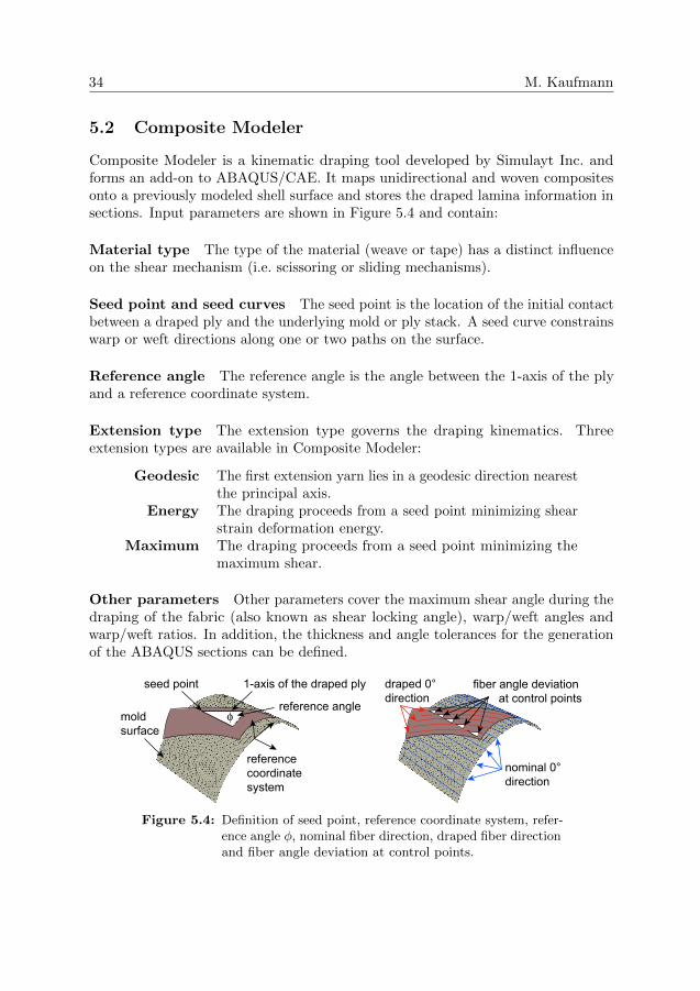
5.2 Composite Modeler
Composite Modeler is a kinematic draping tool developed by Simulayt Inc. andforms an add-on to ABAQUS/CAE. It maps unidirectional and woven compositesonto a previously modeled shell surface and stores the draped lamina information insections. Input parameters are shown in Figure 5.4 and contain:
Material type The type of the material (weave or tape) has a distinct influenceon the shear mechanism (i.e. scissoring or sliding mechanisms).
Seed point and seed curves The seed point is the location of the initial contactbetween a draped ply and the underlying mold or ply stack. A seed curve constrainswarp or weft directions along one or two paths on the surface.
Reference angle The reference angle is the angle between the 1-axis of the plyand a reference coordinate system.
Extension type The extension type governs the draping kinematics. Threeextension types are available in Composite Modeler:
Geodesic The first extension yarn lies in a geodesic direction nearestthe principal axis.
Energy The draping proceeds from a seed point minimizing shearstrain deformation energy.
Maximum The draping proceeds from a seed point minimizing themaximum shear.
Other parameters Other parameters cover the maximum shear angle during thedraping of the fabric (also known as shear locking angle), warp/weft angles andwarp/weft ratios. In addition, the thickness and angle tolerances for the generationof the ABAQUS sections can be defined.
reference coordinate system
seed point
reference angle
1-axis of the draped ply
φmoldsurface
draped 0°direction
fiber angle deviation at control points
nominal 0°direction
Figure 5.4: Definition of seed point, reference coordinate system, refer-ence angle φ, nominal fiber direction, draped fiber directionand fiber angle deviation at control points.

Introduction 35
Use of Composite Modeler
The procedure of using ABAQUS/CAE and Composite Modeler is the following:mesh the part, call the draping plug-in, define layup, material and draping properties(such as seed point location and reference angle), export the flat pattern, and mapthe simulated composite properties back onto ABAQUS sections. During the drapingcalculation, a PJN mesh as shown in Figure 5.1 is applied to the shell surface, andthe internal data points (such as fiber angles and thicknesses) are averaged to sectionproperties. A recently integrated feature allows access to the output data not onlyon the screen, but also by means of a text file (.vfp). The data comprise:
Resulting fiber angles Stored in ABAQUS section definitions, shown on thescreen as a ply stack plot and saved in the .vfp file, the latter containing the internalPJN data points.
Fabric shear Shown on the screen and written to the .vfp file. Colors depictareas where the maximum fabric shear is reached and risk for wrinkling occurs (seeFigure 5.5).
Figure 5.5: Screen shot of the fabric shear modeled in Composite Mod-eler. The area with risk for wrinkling is emphasized withdashes.
Ply thickness The ply thickness is stored as part of the ABAQUS sections. Inaddition, the internal data points of the PJN model are saved to the .vfp file.
Flat pattern The shape of the ply when undraped, see Figure 5.3. This shapeis saved as a drawing exchange format (.dxf) file which can be post-processed bymeans of scripts in order to obtain ply area, scrap ratio and perimeter of the cut,see Lang [75].


6 Cost Optimization Framework
The result of this thesis is a multiobjective optimization framework for aircraftstructures that incorporates cost and weight aspects into the objective function.The framework is designed modularly in order to capture a variety of structures,materials, processes and constraints.
The direct operating cost DOC (Equation (4.2)) was used as the basis andsimplified to the objective function seen below. Thus, only design-driving costaspects were considered to be part of the objective function. The optimizationproblem was formulated as
min DOC of an aircraft component
subject to prescribed load case (6.1)
xi < xi < xi, i = 1 . . . n,
with the direct operating cost given as the weighted sum
DOC = α1Cman + α2Cndt,prod +Nα3Cndt,serv + pW. (6.2)
Cman is the manufacturing cost, Cndt,prod and Cndt,serv are non-destructive testingcosts for in-production and in-service inspection, p is a weight penalty (in e/kg)and W is the weight of the structure. The parameters αi incorporate calibrationfactors due to depreciation, overhead cost and other cost adjustments, and N isthe estimated number of regular inspections during the lifetime of the aircraft. Thefinal framework is illustrated in Figure 6.1.
In Curran’s and Kassapoglou’s work (see Section 3.3), closed-form solutionsprovided the basis for the structural calculation. Here, it was proposed that an FEtool (e.g. ABAQUS) would calculate the structural performance of the component.Thus, the problem was independent from any limitations, such as geometries,material models and boundary conditions. In addition, the setup was reduced to thegeneration of the FE model and its parametrization. A major drawback, however,was the computational effort that was necessary in order to generate the structuralfeedback.
The calculation of the structural constraints emerged to be the limiting factorand a gradient-based method was chosen. The method of moving asymptotes (MMA)was developed by Svanberg and first published in 1987, see [76–78]. This solver
37

38 M. Kaufmann
cost
weight
FE
DOC
solver
+
constraints
objective function
draping database
best ply
design
dkNDT
Figure 6.1: The proposed optimization framework
obtained the results from the different analysis blocks, i.e. SEER-MFG (for thecalculation of the manufacturing cost), ABAQUS/CAE, Composite Modeler andthe NDT model. Based on that feedback, the objective function, the constraintsand the update of the variables were computed.
The approach of a weight penalty p was introduced in the work done by Kellyand Wang [37], Wang et al. [38] and Curran et al. [39]. The quantification of p,however, is not trivial. The literature proposes values between e45/kg and e380/kg,whereas own estimations, based on the fuel consumption of an A330 and today’s fuelprice, resulted in a weight penalty of approximately e2000/kg. A definite value for pcould not be given, as it depended on the viewpoint of the designer, the applicationand the operational profile. Instead, it was concentrated on the effect of differentsettings of the weight penalty p on the design. This was done as follows:
Paper A
A skin/stringer panel was optimized using a simplified version of the objectivefunction formed by the equation DOC = Cman + pW . The weight penalty p wasvaried between 0 and ∞, thus capturing the whole spectrum between pure costoptimization and pure weight optimization. The optimization was done for threematerial configurations: an all-metal, a mixed and an all-composite configuration.The optimal design solution was highly dependent on the weight penalty, and itwas shown that the ideal choice of the design solution was neither low-cost norlow-weight but rather a combination thereof.

Introduction 39
Paper B
A skin/stringer panel was optimized using the objective function given in Equa-tion (6.2). Further, the design strength of each laminate was adjusted accordingto the parameters of non-destructive testing. One of the parameters, the scanpitch, was a representative value for the guaranteed laminate quality. It was shownthat – similar to the results of Paper A – the optimum laminate quality was againdependent on the weight penalty. The designs of the investigated skin/stringerpanels were mainly governed by fulfilling the buckling constraint. As a consequence,the design strength could be lowered by adjusting the scan pitch of the ultrasonictesting, reducing the cost of NDT by 35-54% and the component’s direct operatingcost by 4-14%.
Paper C
The results of Paper A and Paper B showed that the actual cost could even belower than the estimations using prescribed process parameters. Thus, the sub-optimization of machining and other process parameters was necessary in order toestimate the lowest manufacturing cost in each iteration. A framework for the sub-optimization of machining parameters was proposed, minimizing the manufacturingcost in each iteration by the adaptation of manufacturing parameters. The frameworkextension was added to the existing implementation and tested on the center wingbox rear spar of an airliner. Three optimizations were performed, and a low cost, alow weight and an intermediate design solution were found. The difference betweenthe low cost and the low weight solutions was 4.4% in manufacturing cost and 9.7%in weight. Based on these optimizations, the effect of the parameter adaptationmodule was analyzed.
Paper D
The optimization framework was enhanced by a kinematic draping simulation whichallowed the fiber angles to be simulated more realistically. First, a draping knowledgedatabase was generated in which combinations of seed points and reference angleswere evaluated in terms of fiber angle deviation, scrap, ultrasonic cuts and materialshear. Second, the solver picked the best sets of plies during the subsequentoptimization. The methodology was tested by means of a curved C-spar which wasdesigned using plain weave and unidirectional prepreg. It was shown how differentobjectives during the generation of the draping database led to different designsolutions. No non-destructive testing cost was included in this work.
Paper E
The total optimization framework as shown in Figure 6.1 was applied to the designof a curved C-spar. The case study included five material systems: aircraft gradealuminum, two non-crimp fabrics and two types of prepreg. The results were

40 M. Kaufmann
compared in relation to each other and it was shown that (depending on the estimatedfuel burn share of the component) a different material system was favorable whenoptimizing for operating cost. In addition, several what-if scenarios were examined inwhich changes in labor rates, material costs and production quantities were studied.

7 Conclusion
The proposed optimization framework is an approach to include more of the totallife-cycle of the aircraft into the design process than done today. Depending on theviewpoint of the designer, cost and weight are traded differently. Thus, a simplifiedform of the direct operating cost is used to evaluate the merit of a design solution. Aweight penalty is assigned to balance the cost and weight objectives. In combinationwith the proposed NDT and draping tools, the literature’s cost/weight optimizationconcepts are brought forward towards a more holistic view of cost-efficient design.
In each of the case studies, different design solutions were favorable in dependencyof the value of the weight penalty. Thus, the fiber angle distribution, the thicknessesand the stringer configuration changed. It was shown that the engineer should notperform cost or weight optimization alone, but rather a combination thereof.
The cost and the structural model generated good estimates and providedsufficient sensitivity for the shape and size optimization. Under the condition thatthe component was modeled with appropriate elements, a fast convergence rate wasachieved. A drawback of the current form of the framework, however, was the timeneeded to parameterize the models. More work would be necessary to bridge thegap from a CAD model to an applicable optimization setup.
41

8 Future Work
A lot of aspects in the design of aircraft structures were implemented in this work.Nevertheless, there are four fields where future work is proposed.
First, more work is needed to capture the total life-cycle of an airliner alreadyin its design process. Little primary structure made of composite material is flyingtoday, as both the A350 and Boeing’s 787 are still in prototype stages. Therefore,little experience of ageing carbon fiber wings and fuselages exists, and to foreseethe number and thoroughness of inspections is delicate. An enhanced maintenancemodel, repairability and end-of-life aspects could be integrated into the objectivefunction.
Second, it is suggested to enhance the framework by probabilistic design meth-ods. The structural performance, for example, should be robust to manufacturingtolerances, such as angle or thickness deviations, porosities or irregularities in thematerial properties. Thus, the use of a reliability-based optimization frameworkwould enable the design of robust structures.
Third, the NDT cost and the NDT strength reduction models could be improved.The difference between in-production and in-service testing could be more elaborateby applying different scanning techniques and overhead adjustments. Anothersuggestion is the application of the strength reduction as function of the stackingsequence, material properties and manufacturing technique. In addition, a stiffnessreduction due to porosity might be included in the structural model. Beyond that,the inspection interval could be adapted to the stress level and the structural functionof each feature. A probabilistic damage model could be included to capture thepossibility of failure and repair for each structural member.
Finally, one could work on developments for the optimization of the drapingstrategy. In the current state, a restricted set of seed points is included for thegeneration of the draping knowledge database. One could imagine enhancements ofthe methodology where all points of the component’s surface are considered. Theuse of a response surface method could provide that functionality.
43


Bibliography
[1] G. N. Vanderplaats. Structural optimization for statics, dynamics and beyond. Journalof the Brazilian Society of Mechanical Sciences and Engineering, 28(3):316–322, 2006.
[2] T. Gutowski, R. Henderson, and C. Shipp. Manufacturing costs for advanced compos-ites aerospace parts. SAMPE Journal, 27(3):37–43, 1991.
[3] M. Rais-Rohani and E. B. Dean. Toward manufacturing and cost considera-tions in multidisciplinary aircraft design. In Collection of Technical Papers -AIAA/ASME/ASCE/AHS/ASC Structures, Structural Dynamics and Materials Con-ference, volume 4, pages 2602–2612, 1996.
[4] J. Sobieszczanski-Sobieski and R. T. Haftka. Multidisciplinary aerospace designoptimization: survey of recent developments. Structural and Multidisciplinary Opti-mization, 14:1–23, 1997.
[5] C. Soutis. Fibre reinforced composites in aircraft construction. Progress in AerospaceSciences, 41(2):143–151, 2005.
[6] H. Assler. Design of aircraft structures under special consideration of NDT. In JorgVolker, editor, Proceedings of the 9th European NDT Conference (ECNDT), Berlin,2006.
[7] K. Johansen, M. Comstock, and M. Winroth. Coordination in collaborative man-ufacturing mega-networks: A case study. Journal of Engineering and TechnologyManagement - JET-M, 22(3):226–244, 2005.
[8] M. Jacobsen. On improving efficiency of flight using optimization. PhD thesis,Kungliga Tekniska Hogskolan (KTH), Trita-AVE 2009:45, 2009.
[9] G. Marsh. Composites lift off in primary aerostructures. Reinforced Plastics, 48(2-4):22–27, 2004.
[10] M. C. Niu. Airframe Structural Design. Hong Kong Conmilit Press Ltd, Hong Kong,second edition edition, 1996.
[11] NDT Resource Center. Data presentation. retrieved October 24, 2009, fromhttp://www.ndt-ed.org/EducationResources/CommunityCollege/Ultrasonics/ Equip-mentTrans/DataPres.htm, (created on December 19, 2007).
[12] D. Raymer. Enhancing Aircraft Conceptual Design using Multidisciplinary Optimiza-tion. PhD thesis, KTH, Department of Aeronautics, 2002. 91-7283-259-2.
45

46 M. Kaufmann
[13] P. Bartholomew. The role of MDO within aerospace design and progress towards anMDO capability. In Collection of Technical Papers - AIAA/USAF/NASA/ISSMOSymposium on Multidisciplinary Analysis and Optimization, AIAA-1998-4705, pages10–31, 1998.
[14] J. A. Samareh. A survey of shape parameterization techniques. In CEAS/AIAA/ICASE/NASA Langley International Forum on Aeroelasticity and Structural Dynamics,Williamsburg, VA, June 1999.
[15] J. A. Samareh and K. G. Bhatia. A unified approach to modeling multidisciplinaryinteractions. In Proceedings of the 8th AIAA/USAF/NASA/ISSMO Symposium onMultidisciplinary Analysis and Optimization, AIAA-2000-4074, 2000.
[16] J. C. Townsend, J. A. Samareh, R. P. Weston, and W. E. Zorumski. Integration of aCAD system into an MDO framework. Technical report, NASA Langley TechnicalReport Server, 1998.
[17] A. Salas and J. C. Townsend. Framework requirements for MDO application develop-ment. In Collection of Technical Papers - AIAA/USAF/NASA/ISSMO Symposiumon Multidisciplinary Analysis and Optimization, 1998, AIAA-1998-4740, 1998.
[18] R. T. Marler and J. S. Arora. Survey of multi-objective optimization methods forengineering. Structural and Multidisciplinary Optimization, 26(6):369–395, 2004.
[19] K. Gantois and A. J. Morris. The multi-disciplinary design of a large-scale civilaircraft wing taking account of manufacturing costs. Structural and MultidisciplinaryOptimization, 28:31–46, 2004.
[20] L. T. Watson and R. T. Haftka. Modern homotopy methods in optimization. ComputerMethods in Applied Mechanics and Engineering, 74(3):289–305, 1989.
[21] I. Das and J. E. Dennis. Normal-boundary intersection: a new method for generatingPareto optimal points in multicriteria optimization problems. SIAM Journal onOptimization, 8(3):631–657, 1998.
[22] C.-H. Huang, J. Galuski, and C. L. Bloebaum. Multi-objective pareto concurrentsubspace optimization for multidisciplinary design. AIAA Journal, 45(8):1894–1906,2007.
[23] I. Das and J. E. Dennis. Closer look at drawbacks of minimizing weighted sums ofobjectives for pareto set generation in multicriteria optimization problems. StructuralOptimization, 14(1):63–69, 1997.
[24] J.-H. Kang and C.-G. Kim. Minimum-weight design of compressively loaded compositeplates and stiffened panels for postbuckling strength by genetic algorithm. Proceedingsof the 14th International Conference on Composite Materials, 2003.
[25] M. Walker. The effect of stiffeners on the optimal ply orientation and buckling load ofrectangular laminated plates. Computers and Structures, 80(27-30):2229–2239, 2002.
[26] T. S. Geiger and D. M. Dilts. Automated design-to-cost: Integrating costing into thedesign decision. Computer Aided Design, 28(6-7):423–438, 1996.

Introduction 47
[27] B. Heinmuller and D. M. Dilts. Automated design-to-cost: Application in the aero-space industry. In Proceedings - Annual Meeting of the Decision Sciences Institute,volume 3, pages 1227–1229, 1997.
[28] W. J. Marx, D. N. Mavris, and D. P. Schrage. A knowledge-based system integratedwith numerical analysis tools for aircraft life-cycle design. Artificial Intelligence forEngineering Design, Analysis and Manufacturing, 12:211–229, 1998.
[29] J. Scanlan, A. Rao, C. Bru, P. Hale, and R. Marsh. Datum project: Cost estimatingenvironment for support of aerospace design decision making. Journal of Aircraft,43(4):1022–1028, 2006.
[30] C. H. Park, W. I. Lee, and A. Vautrin. Simultaneous optimization of compositestructures considering mechanical performance and manufacturing cost. CompositeStructures, 65(1):117–127, 2004.
[31] M. S. Edke and K. H. Chang. Shape optimization of heavy load carrying componentsfor structural performance and manufacturing cost. Structural and MultidisciplinaryOptimization, 31(5):344–354, 2006.
[32] R. Curran, G. Gomis, S. Castagne, J. Butterfield, T. Edgar, C. Higgins, and C. McK-eever. Integrated digital design for manufacture for reduced life cycle cost. InternationalJournal of Production Economics, 109(1-2):27–40, 2007.
[33] Engineering Sciences Data Unit. Local buckling of compression panels with unflangedintegral stiffeners. ESDU International, Item 70003, 1970.
[34] C. Kassapoglou. Simultaneous cost and weight minimization of composite-stiffenedpanels under compression and shear. Composites Part A: Applied Science and Manu-facturing, 28(5):419–435, 1997.
[35] C. Kassapoglou. Minimum cost and weight design of fuselage frames. part a: Designconstraints and manufacturing process characteristics. Composites Part A: AppliedScience and Manufacturing, 30(7):887–894, 1999.
[36] C. Kassapoglou. Minimum cost and weight design of fuselage frames. part b: Costconsiderations, optimization, and results. Composites Part A: Applied Science andManufacturing, 30(7):895–904, 1999.
[37] D. Kelly, K. Wang, and S. Dutton. A guided tradeoff for cost and weightfor generating optimal conceptual designs. In Collection of Technical Papers -AIAA/ASME/ASCE/AHS/ASC Structures, Structural Dynamics and Materials Con-ference, volume 2, pages 894–904, 2003.
[38] K. Wang, D. Kelly, and S. Dutton. Multi-objective optimisation of composite aerospacestructures. Composite Structures, 57(1):141–148, 2002.
[39] R. Curran, A. Rothwell, and S. Castagne. A numerical method for cost-weight optimisation of stringer-skin panels. In Collection of Technical Papers -AIAA/ASME/ASCE/AHS/ASC Structures, Structural Dynamics and Materials Con-ference, volume 7, pages 5262–5277, 2004.

48 M. Kaufmann
[40] M. Price, R. Curran, A. Murphy, S. Raghunathan, J. Early, S. Castagne, E. Benard,and B. Crawford. Integrating design, manufacturing and cost for trade-offs on aircraftconfigurations. In Collection of Technical Papers - 6th AIAA Aviation Technology,Integration, and Operations Conference, volume 1, pages 373–383, 2006.
[41] S. Castagne, R. Curran, M. Price, P. Collopy, A. Murphy, and S. Raghunathan. Valuedriven design optimization of aircraft structures. In Collection of Technical Papers -6th AIAA Aviation Technology, Integration, and Operations Conference, volume 1,pages 604–611, 2006.
[42] R. Curran, S. Castagne, J. Early, M. Price, S. Raghunathan, J. Butterfield, andA. Gibson. Aircraft cost modelling using the genetic causal technique within a systemsengineering approach. Aeronautical Journal, 111(1121):409–420, 2007.
[43] S. Castagne, R. Curran, A. Rothwell, M. Price, E. Benard, and S. Raghunathan. Ageneric tool for cost estimating in aircraft design. Research in Engineering Design,18(4):149–162, 2008.
[44] S. Castagne, R. Curran, and P. Collopy. Implementation of value-driven optimisa-tion for the design of aircraft fuselage panels. International Journal of ProductionEconomics, 117(2):381–388, 2009.
[45] A. Iqbal and J. S. Hansen. Cost-based, integrated design optimization. Structural andMultidisciplinary Optimization, 32(6):447–461, 2006.
[46] J. Roskam. Airplane Design Part VIII: Airplane Cost Estimation Design Developmentand Manufacturing and Operating. Darcorporation, 1990.
[47] Y. Asiedu and P. Gu. Product life cycle cost analysis: state of the art review.International Journal of Production Research, 36(4):883–908, 1998.
[48] S. K. Durairaj, S. K. Ong, A. Y. C. Nee, and R. B. H. Tan. Evaluation of life cyclecost analysis methodologies. Corporate Environmental Strategy, 9(1):30–39, 2002.
[49] D. G. Woodward. Life cycle costing - theory, information acquisition and application.International Journal of Project Management, 15(6):335–344, 1997.
[50] J. V. Michaels and W. P. Wood. Design to cost. John Wiley and Sons Inc., 1989.
[51] E. B. Dean and R. Unal. Elements of designing for cost. In Proceedings of the AIAA1992 Aerospace Design Conference, Irvine, CA, February 1992.
[52] R. Curran, S. Raghunathan, and M. Price. Review of aerospace engineering costmodelling: The genetic causal approach. Progress in Aerospace Sciences, 40(8):487–534,2004.
[53] D. M. Anderson. Design for Manufacturability. CIM Press, 1990.
[54] P. Dewhurst and G. Boothroyd. Design for assembly: automatic assembly. MachineDesign, 56(2):87–92, 1984.
[55] P. Dewhurst and G. Boothroyd. Design for assembly: robots. Machine Design,56(4):72–76, 1984.
[56] G. Boothroyd. Product design for manufacture and assembly. Computer Aided Design,26(7):505–520, 1994.

Introduction 49
[57] S. Miyakawa and T. Ohashi. The hitachi new assemblability evaluation method(AEM). In Proceedings of the Ontario Conference on Product Design for Assembly,Newport, RI, USA, 1986.
[58] J. Wilson et al. Integrated Product and Process Development. The National Centerfor Advanced Technologies, 1994.
[59] A. Niazi, J. S. Dai, S. Balabani, and L. Seneviratne. Product cost estimation:Technique classification and methodology review. Journal of Manufacturing Scienceand Engineering, Transactions of the ASME, 128(2):563–575, 2006.
[60] Y. Wei and P. J. Egbelu. A framework for estimating manufacturing cost fromgeometric design data. International Journal of Computer Integrated Manufacturing,13(1):50–63, 2000.
[61] A. C. Long. Composites forming technologies. Woodhead Publishing Ltd, 2007.
[62] C. Mack and H. M. Taylor. The fitting of woven cloth to surfaces. Journal of theTextile Institute, (47):477–488, 1956.
[63] B. P. Van West, R. B. Pipes, and M. Keefe. A simulation of the draping of bidirectionalfabrics over arbitrary surfaces. Journal of the Textile Institute, 81(4):448–460, 1990.
[64] K. Potter. Bias extension measurements on cross-plied unidirectional prepreg. Com-posites Part A: Applied Science and Manufacturing, 33(1):63–73, 2002.
[65] K. Potter. Beyond the pin-jointed net: Maximising the deformability of aligned con-tinuous fibre reinforcements. Composites Part A: Applied Science and Manufacturing,33(5):677–686, 2002.
[66] K. Potter. In-plane and out-of-plane deformation properties of unidirectional preim-pregnated reinforcement. Composites Part A: Applied Science and Manufacturing,33A(11):1469–77, 2002.
[67] J. Wang, R. Paton, and J. R. Page. Draping of woven fabric preforms and prepregs forproduction of polymer composite components. Composites Part A: Applied Scienceand Manufacturing, 30(6):757–765, 1999.
[68] J. Wiggers. Analysis of Textile Deformation during Preforming for Liquid CompositeMoulding. PhD thesis, University of Nottingham, 2007.
[69] M. Nguyen, I. Herszberg, and R. Paton. The shear properties of woven carbon fabric.Composite Structures, 47(1):767–779, 1999.
[70] P. Boisse, B. Zouari, and J.-L. Daniel. Importance of in-plane shear rigidity in finiteelement analyses of woven fabric composite preforming. Composites Part A: AppliedScience and Manufacturing, 37(12):2201–2212, 2006.
[71] P. Badel, E. Vidal-Salle, and P. Boisse. Computational determination of in-plane shearmechanical behaviour of textile composite reinforcements. Computational MaterialsScience, 40(4):439–448, 2007.
[72] Y. Larberg. Deformability of unidirectional prepreg materials. Licentiate Thesis,Kungliga Tekniska Hogskolan (KTH), Trita-AVE 2009-32, 2009.

50 M. Kaufmann
[73] O. Guillermin. Computer-aided design and manufacturing. ASM Handbook Volume21, Composites, pages 366–372, 2001.
[74] A. A. Skordos, C. Monroy Aceves, and M. P. F. Sutcliffe. Drape optimisation inwoven composite manufacturing. In Proceedings of the 5th International Conferenceon Inverse Problems in Engineering: Theory and Practice, 2005.
[75] A. Lang. Numerical simulation of draping and cutting of CFRP prepregs. Bachelorthesis 08-026, Eidgenossische Technische Hochschule Zurich (ETHZ) and KungligaTekniska Hogskolan (KTH), 2008.
[76] K. Svanberg. Method of moving asymptotes – a new method for structural optimization.Journal for Numerical Methods in Engineering, 24(2):359–373, 1987.
[77] K. Svanberg. A globally convergent version of MMA without linesearch. In Proceedingsof the First World Congress of Structural and Multidisciplinary Optimization, Goslar(Germany), pages 9–16, May/June 1995.
[78] M. Bruyneel, P. Duysinx, and C. Fleury. A family of MMA approximations forstrutural optimization. Structural and Multidisciplinary Optimization, 2002.

Division of work between authors
Paper A
Kaufmann was responsible for the implementation and the numerical experiments.The analysis of the results was performed jointly by the authors. The paper waswritten by Kaufmann with support from Zenkert.
Paper B
Mattei proposed the cost model. The implementation, the experiments and theanalysis of the results were performed by Kaufmann. The paper was written byKaufmann with support from Zenkert.
Paper C
Czumanski implemented the framework under Kaufmann’s supervision. Kaufmannand Czumanski jointly carried out the case study. The paper was written byKaufmann with support from Czumanski and Zenkert.
Paper D
Kaufmann carried out the implementation of the framework, the numerical experi-ments and the analysis of the results. The paper was written by Kaufmann withsupport from Zenkert and Akermo.
Paper E
Kaufmann carried out the numerical experiments and the analysis of the results.The paper was written by Kaufmann with support from Zenkert and Akermo.
51


Part II
Appended papers
53