Embed Size (px)
Citation preview

COST SAVINGS THROUGH MULTIMISSION CODE REUSE FOR MARS IMAGEPRODUCTS
Robert G. Deen
Space Science Data Systems SectionJet Propulsion Laboratory
Mail Stop 168-514Pasadena, CA 91109
ABSTRACT
NASA has sent, and continues to send, many missions tothe Martian surface. These landers and rovers typicallyhave onboard stereo cameras that take in-situ pictures of thesurface. The Multimission Image Processing Lab (MIPL)at JPL has written a reusable software suite to handle thesekinds of surface-based cameras. Called PIG (PlanetaryImage Geometry), it consists of an object-oriented,multimission framework which abstracts out elementscommon to all surface-based missions. To this are addedmission-specific modules (subclasses). The applicationprograms themselves, performing tasks such as mosaicking,pointing correction, stereo correlation, and terraingeneration, do not need to be rewritten for each newmission, and contain no mission-specific referenceswhatsoever.
The cost of adaptation to a new mission is very smallcompared to the cost to rewrite the application suite eachtime. Mission adaptation time has ranged from a few daysto two months, compared to years to write the original code.This frees up a lot of resources that can be used to extendthe library and provide additional functionality, rather thanre-implementing the core functions each time.
So far the library has been adapted for use with MarsPathfinder, Mars Polar Lander, the Mars ’01 AthenaTestbed, the FIDO test rover, and the Mars ExplorationRovers (MER). In the case of MER, basic capability wasavailable even before ATLO, enabling use during testingand allowing time to work on functionality new to themission, such as support for long-range traverses.
Several challenges to multimission use remain, however.Chief among them is the historic trend to redesign metadata(image labels) for each mission; support for this tends to bea driving factor in adaptation time. Future missions would
be well served to use existing metadata designs as much aspossible in order to minimize costs.
An overview of the library’s design will be presented, alongwith mission adaptation experiences and lessons learned,and the kinds of additional functionality that have beenadded while still retaining its multimission character. Theapplication programs using the library will also be brieflydescribed.
1. INTRODUCTION
NASA’s exploration of Mars has increasingly focused onin-situ, landed missions. These landers and rovers haveonboard stereo frame cameras that take images of thesurface. The Multimission Image Processing Lab (MIPL)at JPL has been tasked with processing these images forscience, operations, and public affairs. A number ofproducts are derived from the images, including mosaicsand terrain.
The current trend began with the highly successful MarsPathfinder (MPF) in 1997. Mars Polar Lander (MPL) failedin 1999, but the ground system at MIPL was in place andready to go. MIPL provided support for the Mars ’01Athena testbed (intended for a 2001 lander, which wascancelled), and the Field Integrated Design & Operations(FIDO) rover testbed. Most recently, MIPL is providingsupport for the twin Mars Exploration Rovers (MER),slated for launch in June, 2003. Looking forward, the MarsScience Laboratory and other landed missions are in theplanning stages, which MIPL is planning on supporting.
While the missions have many similarities, each one isdifferent, and the software used to produce the imageproducts must be adapted for each mission. This paperdescribes how MIPL has reused the bulk of this softwarefor each mission by creating a multimission framework.

2. PROBLEM DOMAIN
Before describing the software itself, some background onthe input images for these missions and the output productsproduced by MIPL will be helpful.
2.1. Input Images
The input images for all of these missions are similar. ACCD array in a frame camera produces monochromeimages ranging from 248x256 pixels (MPF) to 1024x1024(MER). Images typically have 8 or 12 bits per pixel. Thecameras are either fixed to the body of the lander or rover,or are on an articulating device such as a mast or arm.Color images are produced from some cameras by a filterwheel in the optical path. [1,6,7,9] The images are oftenstereoscopic, i.e. pairs of left and right images taken at thesame time from slightly different vantage points. Suchstereo images are processed more than their non-stereocousins, as terrain data can be derived from stereo pairs.
The input images all contain some sort of metadata (a.k.a.image labels) which describe the conditions under whichthe image was taken - exposure, pointing, compression,temperature, instrument modes, etc. [1,7,9] These labels arecritical for determining how to interpret and use the images.For example, mosaics are assembled by looking at the labelfor each image to determine where the camera was pointing(e.g. mast articulation angles) and using that to control themosaic ray-tracing process.
2.2. Output Products
There are many different output products that can begenerated using the MIPL software suite described herein.Some examples will be shown, and the actual programnames are in parentheses for reference.
Mosaics: The mosaics seem to be the most popular outputproducts for science and public use. Since each inputimage has a relatively narrow field of view, many images
Figure 1: Mosaics taken by MER-2 during ATLO processing at Kennedy Space Center in March, 2003. Top is a360° cylindrical panorama using 30 frames; bottom is a vertical projection (same data) showing the rover itself.

must be stitched together to create a panoramic view of thescene. It can take over 200 images to create a completepanorama for some instruments.
Mosaics are created by a ray-tracing process. Conceptually,the input images are projected out into space via theircamera model (a mathematical model that describes therelationship between line/sample in the image and x/y/z in3-D space), laid on top of a surface (usually a flat plane),and then are projected back into the output mosaic. [2]
The output can be in one of five projections (using threeprograms): Cylindrical (marsmap), Polar (marsmap),Vertical (marsmap), Perspective (marsmos), or a hybridCylindrical-Perspective projection (marsmcauley). Eachprojection has its advantages and disadvantages. Examplesof the cylindrical and vertical projections are shown inFigure 1.
Pointing Correction: The spacecraft’s knowledge of whereits cameras are pointed is not precise. Mechanical backlashon articulation joints is a primary cause, but there areothers. For this reason, several methods are available tocorrect the pointing by analyzing the images, using eitherautomated/semi-automated (marstie, marsnav) or manual(MICA) methods. Correction can be based on physicalmodeling, or unconstrained. The results feed back into themosaic program in order to reduce seams between frames.
Linearization (marscahv): Input images are often “warped”to remove lens distortion so that they can be described by alinear camera model. This model is epipolar aligned,meaning that lines in stereo images match up, makingcorrelations easier. An example is shown in Figure 2.
Radiometric correction (marsrad, mosaics): This may beapplied independently, or through the mosaic programs.
Figure 2: Images taken by a MER testbed rover by the left front hazard avoidance camera. Left is the raw image;right is the same image after linearization. Note how straight lines become straight once lens distortion is removed.
Figure 3: Stereo images from a MER testbed rover front hazard avoidance camera. Left: the linearized left eye.Middle: the linearized right eye. Right: the XYZ image derived from the stereo pair. A “contour” stretch has beenapplied in order to show the coordinate grid lines. Red lines represent constant X values, green lines representconstant Y, and blue lines represent constant Z.
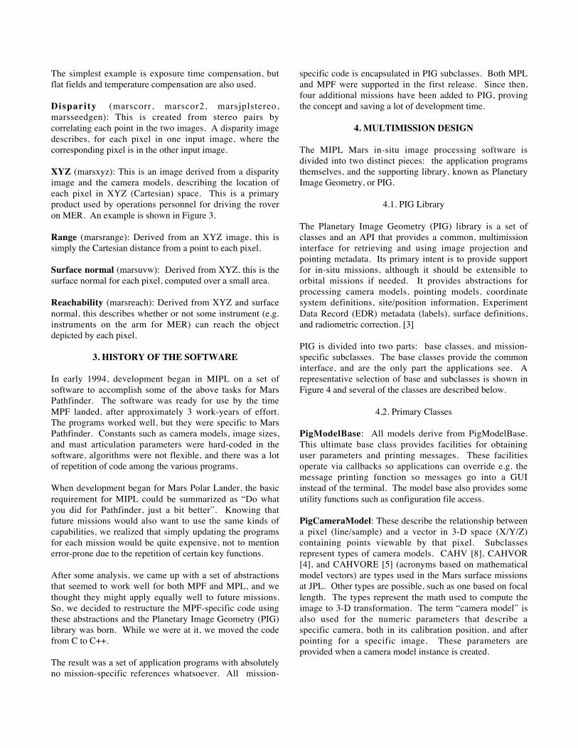
The simplest example is exposure time compensation, butflat fields and temperature compensation are also used.
Disparity (marscorr, marscor2, marsjplstereo,marsseedgen): This is created from stereo pairs bycorrelating each point in the two images. A disparity imagedescribes, for each pixel in one input image, where thecorresponding pixel is in the other input image.
XYZ (marsxyz): This is an image derived from a disparityimage and the camera models, describing the location ofeach pixel in XYZ (Cartesian) space. This is a primaryproduct used by operations personnel for driving the roveron MER. An example is shown in Figure 3.
Range (marsrange): Derived from an XYZ image, this issimply the Cartesian distance from a point to each pixel.
Surface normal (marsuvw): Derived from XYZ, this is thesurface normal for each pixel, computed over a small area.
Reachability (marsreach): Derived from XYZ and surfacenormal, this describes whether or not some instrument (e.g.instruments on the arm for MER) can reach the objectdepicted by each pixel.
3. HISTORY OF THE SOFTWARE
In early 1994, development began in MIPL on a set ofsoftware to accomplish some of the above tasks for MarsPathfinder. The software was ready for use by the timeMPF landed, after approximately 3 work-years of effort.The programs worked well, but they were specific to MarsPathfinder. Constants such as camera models, image sizes,and mast articulation parameters were hard-coded in thesoftware, algorithms were not flexible, and there was a lotof repetition of code among the various programs.
When development began for Mars Polar Lander, the basicrequirement for MIPL could be summarized as “Do whatyou did for Pathfinder, just a bit better”. Knowing thatfuture missions would also want to use the same kinds ofcapabilities, we realized that simply updating the programsfor each mission would be quite expensive, not to mentionerror-prone due to the repetition of certain key functions.
After some analysis, we came up with a set of abstractionsthat seemed to work well for both MPF and MPL, and wethought they might apply equally well to future missions.So, we decided to restructure the MPF-specific code usingthese abstractions and the Planetary Image Geometry (PIG)library was born. While we were at it, we moved the codefrom C to C++.
The result was a set of application programs with absolutelyno mission-specific references whatsoever. All mission-
specific code is encapsulated in PIG subclasses. Both MPLand MPF were supported in the first release. Since then,four additional missions have been added to PIG, provingthe concept and saving a lot of development time.
4. MULTIMISSION DESIGN
The MIPL Mars in-situ image processing software isdivided into two distinct pieces: the application programsthemselves, and the supporting library, known as PlanetaryImage Geometry, or PIG.
4.1. PIG Library
The Planetary Image Geometry (PIG) library is a set ofclasses and an API that provides a common, multimissioninterface for retrieving and using image projection andpointing metadata. Its primary intent is to provide supportfor in-situ missions, although it should be extensible toorbital missions if needed. It provides abstractions forprocessing camera models, pointing models, coordinatesystem definitions, site/position information, ExperimentData Record (EDR) metadata (labels), surface definitions,and radiometric correction. [3]
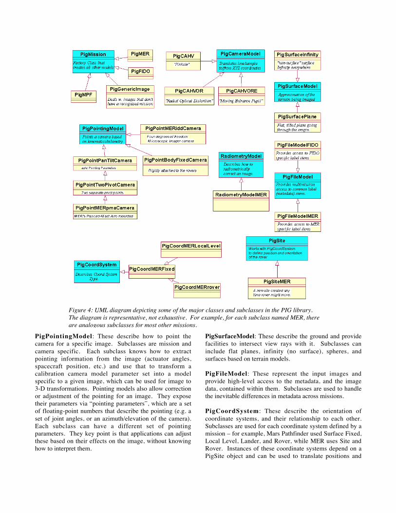
PIG is divided into two parts: base classes, and mission-specific subclasses. The base classes provide the commoninterface, and are the only part the applications see. Arepresentative selection of base and subclasses is shown inFigure 4 and several of the classes are described below.
4.2. Primary Classes
PigModelBase: All models derive from PigModelBase.This ultimate base class provides facilities for obtaininguser parameters and printing messages. These facilitiesoperate via callbacks so applications can override e.g. themessage printing function so messages go into a GUIinstead of the terminal. The model base also provides someutility functions such as configuration file access.
PigCameraModel: These describe the relationship betweena pixel (line/sample) and a vector in 3-D space (X/Y/Z)containing points viewable by that pixel. Subclassesrepresent types of camera models. CAHV [8], CAHVOR[4], and CAHVORE [5] (acronyms based on mathematicalmodel vectors) are types used in the Mars surface missionsat JPL. Other types are possible, such as one based on focallength. The types represent the math used to compute theimage to 3-D transformation. The term “camera model” isalso used for the numeric parameters that describe aspecific camera, both in its calibration position, and afterpointing for a specific image. These parameters areprovided when a camera model instance is created.
PigPointingModel: These describe how to point thecamera for a specific image. Subclasses are mission andcamera specific. Each subclass knows how to extractpointing information from the image (actuator angles,spacecraft position, etc.) and use that to transform acalibration camera model parameter set into a modelspecific to a given image, which can be used for image to3-D transformations. Pointing models also allow correctionor adjustment of the pointing for an image. They exposetheir parameters via “pointing parameters”, which are a setof floating-point numbers that describe the pointing (e.g. aset of joint angles, or an azimuth/elevation of the camera).Each subclass can have a different set of pointingparameters. They key point is that applications can adjustthese based on their effects on the image, without knowinghow to interpret them.
PigSurfaceModel: These describe the ground and providefacilities to intersect view rays with it. Subclasses caninclude flat planes, infinity (no surface), spheres, andsurfaces based on terrain models.
PigFileModel: These represent the input images andprovide high-level access to the metadata, and the imagedata, contained within them. Subclasses are used to handlethe inevitable differences in metadata across missions.
PigCoordSystem : These describe the orientation ofcoordinate systems, and their relationship to each other.Subclasses are used for each coordinate system defined by amission – for example, Mars Pathfinder used Surface Fixed,Local Level, Lander, and Rover, while MER uses Site andRover. Instances of these coordinate systems depend on aPigSite object and can be used to translate positions and
Figure 4: UML diagram depicting some of the major classes and subclasses in the PIG library.The diagram is representative, not exhaustive. For example, for each subclass named MER, thereare analogous subclasses for most other missions.

orientations from any coordinate frame to any other, at leastwithin a single mission.
PigSite: These define the position of a movable object, suchas a rover or lander, at one specific instant. They workclosely with PigCoordSystem objects to provide coordinateframe conversions. The base class defines a site using aquaternion and offset; subclasses may be necessary if otherrepresentations are needed. PigSite has been greatlyexpanded for MER, where long-range traverses create manydifferent Sites which must be tracked.
RadiometryModel: These describe how to correct theradiometry (or brightness) of an image. This can includethings like dark current, flat field, exposure time, andtemperature correction. Subclasses are generally permission, or instrument.
PigLabelModel: A recent addition, these classes handlewriting output labels (metadata) for each type of imageproduct. Subclasses exist per mission, where the metadataformat deviates from the “standard” output labels.
PigMission: Mission objects contain factory methodswhich create all of the other objects described above.Subclasses exist per mission, and know which specificsubclass to create for any given occasion. Subclasses oftenexamine the metadata of an image (via the PigFileModel) todetermine which subclass to create (e.g. which instrumentgenerated the image).
Component Approx. Lines of CodeApplications 66,500PIG library (total) 27,700 PIG multimission base 14,600 PIG MPF 2,100 PIG MPL 2,800 PIG M01 1,200 PIG Generic 1,300 PIG FIDO 2,600 PIG MER 3,100
Table 1: Lines of Code for MIPL in-situ image processing
4.3. Application Programs
As described previously, the application programs containabsolutely no mission-specific code. They work the sameregardless of the mission. Furthermore, when applicationcapabilities are enhanced, old missions are able to takeadvantage of the new features just as well as the newmissions. The available applications are described inSection 2.2.
Lest one think that the applications are trivial, and all thecode is in PIG, Table 1 shows the lines-of-code breakdown
for the software suite as of the time this paper was written.The application code is almost 2.5 times larger than the PIGlibrary itself,
5. ADAPTATION EXPERIENCES
The PIG library has now been adapted to work with datafrom 6 distinct “missions” (5 real missions and a “generic”mission). Adaptation times have ranged from 2 days to afew months. Compare this with 3 years to write the originalcode and one finds that new missions can be supported inabout 1/20 the time it took to write the original library.While algorithm development certainly contributed a lot tothe time required to write the original code, the difference isstill dramatic. Adaptation of the original code, without thePIG library, would probably take 4-5 times longer, and bemore error-prone due to the required duplication of effortand divergent versions.
As shown in Table 1, each mission averages just 2200 linesof mission-specific code. Compare that to 14,600 for thePIG base and 66,500 for the applications, and it should beobvious the extent to which the multimission frameworkhas saved time, money and effort.
5.1. Mars Polar Lander/Mars Pathfinder
These two missions are lumped together because they weredeveloped simultaneously, along with the basic PIGframework. This makes determination of the time to doeither adaptation by itself nearly impossible. The entireMPL task, which included creating the abstraction layer,writing PIG, adapting to MPL and retrofitting MPF, andadding additional application functionality required byMPL, took approximately 1 work year. It is this author’sestimate that the MPL adaptation, if done separately withthe framework in place, would have taken perhaps 6 weeks,and MPF perhaps 3 weeks.
5.2. Mars ’01
Before MPL failed, there were plans for a lander in the2001 time frame. A testbed for this was actually built, andthe PIG library was adapted to work with this testbed.Owing to the similarity to MPF and MPL and the heavy useof cut-and-paste, the adaptation took (by actualmeasurement) 2 days.
5.3. Generic “Mission”
In order to support ad-hoc images, a generic “mission” wasdeveloped, which requires that the camera model be presentin the image label or ancillary file, but no other informationis needed. This adaptation took an estimated 1 week.

5.4. FIDO
The FIDO testbed rover is a close analogue to MER andwas used to test concepts for MER. Support for this tookabout 3 weeks.
5.5. MER
Many enhancements have been made to the PIG library andapplications for MER. Most of these are in order to supportadditional capabilities and requirements that MER has butprevious missions don’t (see Section 6). As such, it is hardto estimate the pure adaptation time (plus, as of this writing,it is not entirely complete), but it is probably around 2 workmonths, most of which has been spent dealing with aredesigned label format.
One nice thing about MER is that we were able to use thegeneric “mission” immediately with the very first images.Thus we had much of the MIPL functionality availableeven before ATLO, which has helped tremendously in earlytesting. As the development team got MER-specificcapabilities working, the results simply got better.
6. EXTENDING THE LIBRARY
One measure of the quality of a design is how easy it is toadd new capabilities or features to the design after thebaseline has been built. Assumptions made early on in thedesign process can come back to haunt you if additionalrequirements change those assumptions. It may be easy, oralmost impossible, to adapt to such changes. On this score,the PIG library design has been successful so far. Toillustrate, a few of the more significant enhancements aredescribed here.
6.1. Coordinate systems
The first version of PIG implicitly assumed one coordinatesystem would be used for all 3-D coordinates used in thegeometry calculations. About 2 months before the landingof MPL, the science team decided they wanted to changethe definitions of several important coordinate systems,with the result that they were no longer compatible andconversions would be required. A month of intense effortfollowed, resulting in an overhaul of the system such thatevery 3-D coordinate is now tagged with the coordinatesystem in which it is measured, and conversions betweensystems are handled automatically by the framework. Themodifications were ready in time for operations.
6.2. New Camera Model Type
Previous missions used the CAHV (linear) camera model,[8] and the CAHVOR (adds radial distortion) model [4].However, MER has extremely wide field-of-view hazard
avoidance cameras (close to 180 degrees), which cannot besuccessfully modeled by CAHV or CAHVOR. A new typeof model that handles fisheye and wide field-of-viewcameras, CAHVORE [5] (developed elsewhere at JPL),was integrated into the PIG framework in about 1.5 weeks.
6.3. Multiple Sites
MER is a long-range rover. As such, it can travel to areasout of view of the original landing site. In order to dealwith this, the concept of multiple Site frames wasintroduced. Each Site frame is a reference for all activitiescontained within the Site. The support for this is quiteinvolved and includes maintaining XML files containingthe Site locations, as well as locations of interest within theSite. This concept fit rather well into the PIG library, at acost of perhaps 4 work months. Interestingly enough, theapplication modifications to support this were extremelyminor (mostly adding a few parameters and help updates);most of the changes are encapsulated in PIG itself, and aretransparent to the applications.
6.4. Output Label Models
The metadata (labels) for MER are a radical departure fromprevious missions (see Section 7). While the input side washandled using the existing PigFileModel, output of labelshad previously been something the applications themselvesdid. It quickly became obvious that a PIG model wasneeded to handle output labels as well, allowing them to bedifferent for different missions. Total time to implementthis, including the model itself and all the actual outputlabels for MER, was approximately 4 work weeks.
7. LESSONS LEARNED
While the PIG library concept and implementation haveperformed admirably, with huge cost savings, there are afew lessons that can be learned from the experience, whichcould save even more money in the future.
7.1. Labels (Metadata)
Most important is the design of the image labels (metadata).Historically, each mission has redesigned their labelstructures virtually from scratch. Label contents are oftenthe subject of heated debate among the operations andscience teams, and it is all too easy to depart from existingnorms in order to make this mission “better”. This wreakshavoc with multimission designs; a lot of new code must bewritten to accommodate the vagaries of label structures.
Well over half of the MER adaptation time, and most of thetime spent creating the output label model, is attributable tochanges in the MER label structure with respect to the“baseline” we hoped would be established by MPL. That’s

easily over two work months just in implementation, notcounting the time spent designing, debating, anddocumenting the label changes.
As a counter-example, the extraordinarily fast adaptationtime for M01 was largely due to the fact that no new labelswere designed; the MPL label structure was simply re-used.
Missions will be well served in the future to simply adoptexisting metadata standards with only minor modifications.This should help all multimission programs, not just theMIPL software suite.
7.2. Other Lessons
In hindsight, it is easy to say that these programs shouldhave been implemented using a multimission frameworkfrom the beginning, for Pathfinder. However, that may nothave been practical. Experience derived during algorithmdevelopment in that first program set was critical indetermining just what abstractions were necessary and whatdidn’t make sense. Spending time to create a frameworkfor functionality that is later discarded is just time wasted.
Thus, developing the algorithms first, then going back andmaking them reusable, seems to have been the right idea forthis software set, at least. You do have to know whatyou’re trying to build, before you can figure out theabstractions that will make the code reusable and adaptable.
It is worthwhile taking the time to thoroughly analyze thesituation before creating a reusable framework. This authorstudied the situation for nearly 2 months, becoming familiarwith the MPF code, before beginning the actual design andimplementation of the PIG library. As detailed elsewherein this paper, this forethought appears to have paid off.
The generic “mission” has come in quite handy. Asmentioned in Section 5.5, it allowed MIPL to process MERdata even before ATLO, before MER-specific developmenthad begun.
8. CONCLUSION
The multimission framework embodied in the PIG libraryhas had a tremendous impact on the ability of MIPL toquickly and inexpensively support new missions. As Table1 shows, only about 2-3% of the code base needs to betouched in order to support a new mission. This is reflectedin the adaptation times described in Section 5. Newmissions can be supported in approximately 1/20 the time ittook to write the original library. This cost savings caneither be returned to the customer, or invested in improvingthe products themselves via better algorithms or newfeatures — an activity that benefits all prior missions aswell as the one under development.
9. ACKNOWLEDGEMENTS
The original MPF code was developed by Jean Lorre. ThePIG library was designed by Bob Deen. Contributors to thelibrary also include Oleg Pariser, Justin Maki, and AntonIvanov. All are from JPL’s Space Science Data SystemsSection (382). Development funding was provided byJPL’s Science Instrument Services, and the Projects.
10. REFERENCES
[1] Alexander, D., et al, “Mars Exploration Rover ProjectSoftware Interface Specification (SIS) CameraExperiment Data Record (EDR) and Reduced DataRecord (RDR) Operations Data Products”. JPL D-22846, 2003.
[2] Deen, R., O. Pariser and J. Lorre, “Creation of Surface-Based Image Mosaics for MER/FIDO”. JPL ITSymposium poster session, Nov. 4, 2002.
[3] Deen, R. and H. Mortensen, “Planetary Image Geometry(PIG) Application Programming Interface (API) andLibrary Software Requirements Document (SRD)Version 1.0”. JPL Internal Document, Dec. 3, 2001.
[4] Gennery, D.B., “Least-Squares Camera CalibrationIncluding Lens Distortion and Automatic Editing ofCalibration Points”, Calibration and Orientation ofCameras in Computer Vision, Springer-Verlag, 2001,p.123-136.
[5] Gennery, D.B., “Generalized Camera CalibrationIncluding Fish-Eye Lenses”, to be published, 2003.<http://eis.jpl.nasa.gov/~telitwin/public-jpl/src/ccal/ccal-references.html>.
[6] Maki, J.N. et al, “The Mars Exploration RoverEngineering Cameras”, Journal of GeophysicalResearch - Planets, MER special issue, publicationpending (2003).
[7] Runkle, R., “Mars Pathfinder Project Imager for MarsPathfinder (IMP) Experiment Data Record (EDR)”.JPL D-12003, 1998.
[8] Yakimovsky, Y. and R. Cunningham, “A System forExtracting Three-Dimensional Measurements from aStereo Pair of TV Cameras”, Computer Graphics andImage Processing, vol, 7, p. 195-210, 1978.
[9] Zamani, P., “Mars Surveyor Project Mars Volatiles AndClimate Surveyor (MVACS) Experiment Data Record(EDR) Software Interface Specification (SIS)”. JPL D-17891, 1998