Embed Size (px)
DESCRIPTION
Trouble shooting
Citation preview
Counter Circuits and Applications
Group 6彭柏源 袁鋒 陳康本
OverviewAnalysis of Sequential Circuits.Ripple Counters.
Design of Divide-by-N Counters.Ripple Counter ICs.Applications.
System Design Applications.Seven-Segment LED Display Decoders.
Synchronous Counters.Synchronous Up/Down-Counter ICs.Applications.
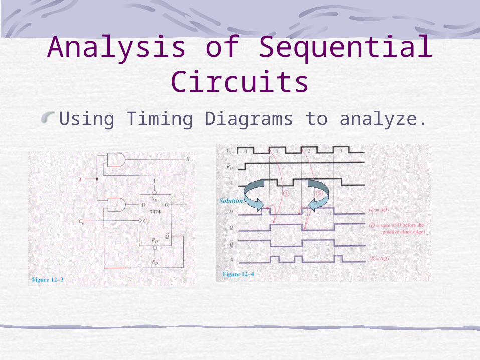
Analysis of Sequential Circuits
Using Timing Diagrams to analyze.
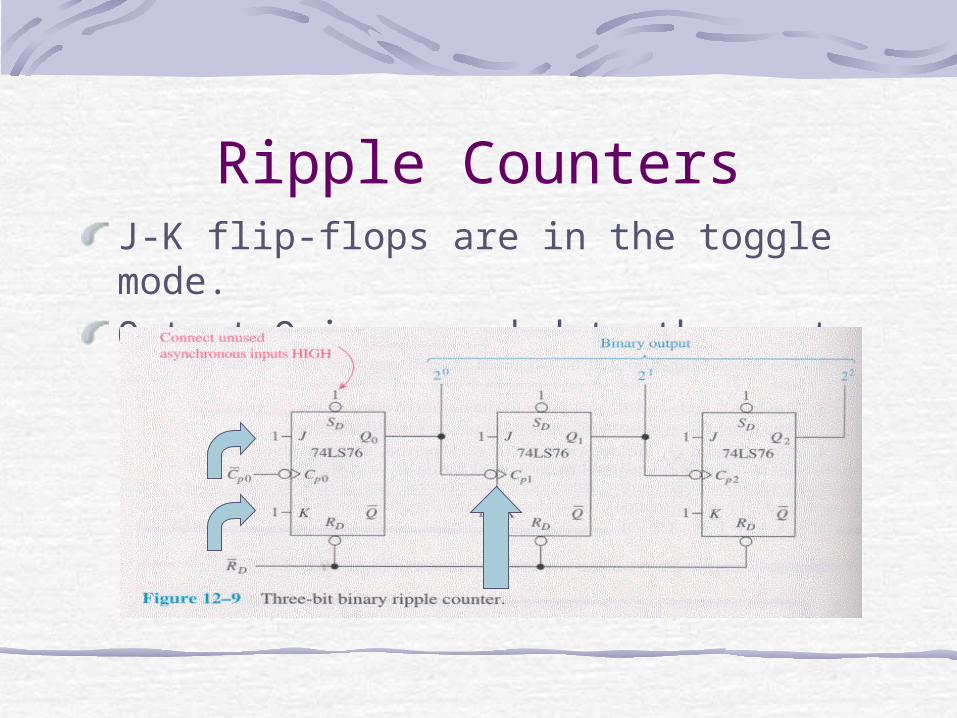
Ripple CountersJ-K flip-flops are in the toggle mode.Output Q is cascaded to the next clock input.
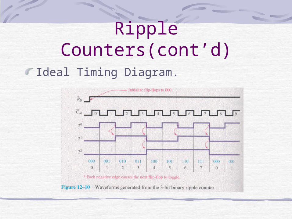
Ripple Counters(cont’d)Ideal Timing Diagram.
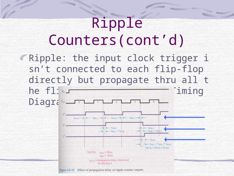
Ripple Counters(cont’d)Ripple: the input clock trigger isn’t connected to each flip-flop directly but propagate thru all the flip-flops. Non-ideal Timing Diagram:
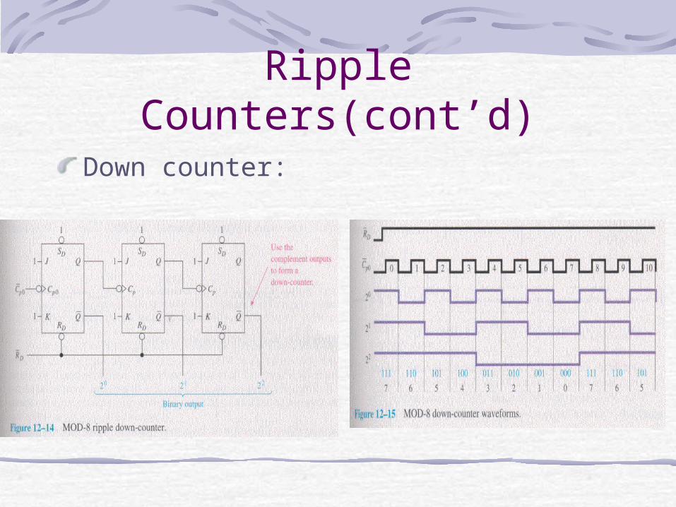
Ripple Counters(cont’d)Down counter:
Design of Divide-by-N Counters
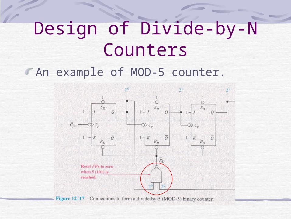
An example of MOD-5 counter.
Design of Divide-by-N Counters (cont’d)
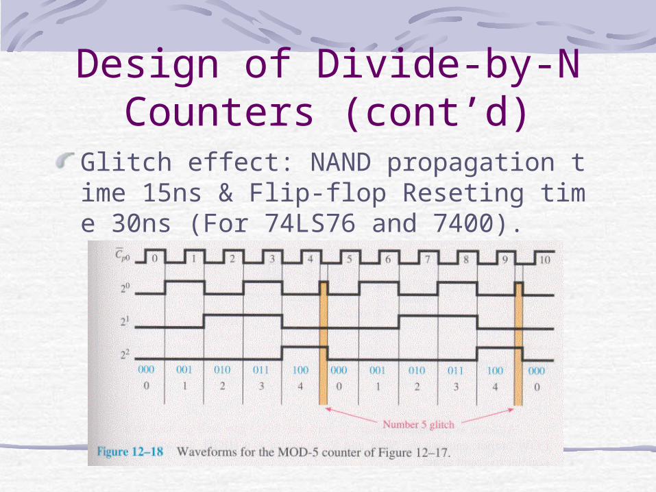
Glitch effect: NAND propagation time 15ns & Flip-flop Reseting time 30ns (For 74LS76 and 7400).
Design of Divide-by-N Counters (cont’d)
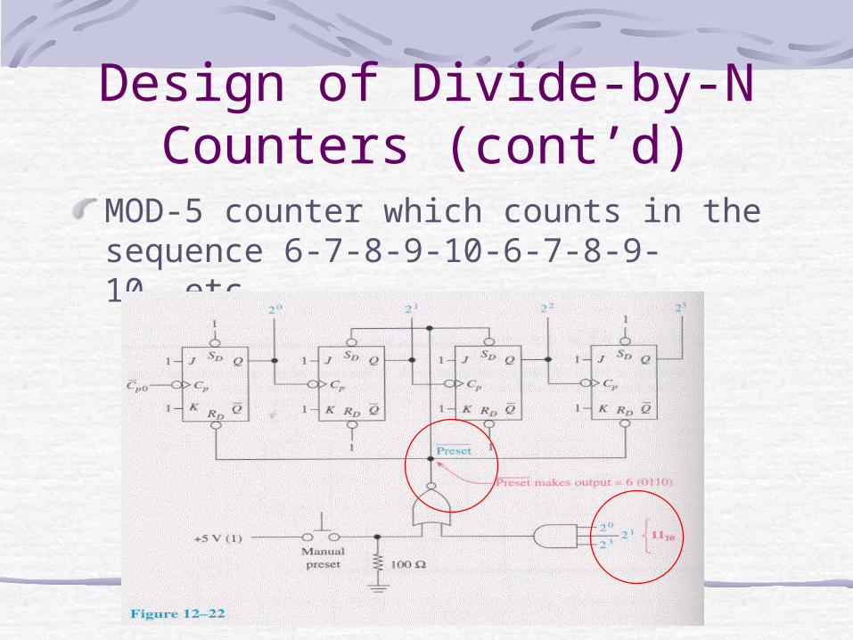
MOD-5 counter which counts in the sequence 6-7-8-9-10-6-7-8-9-10-,etc.
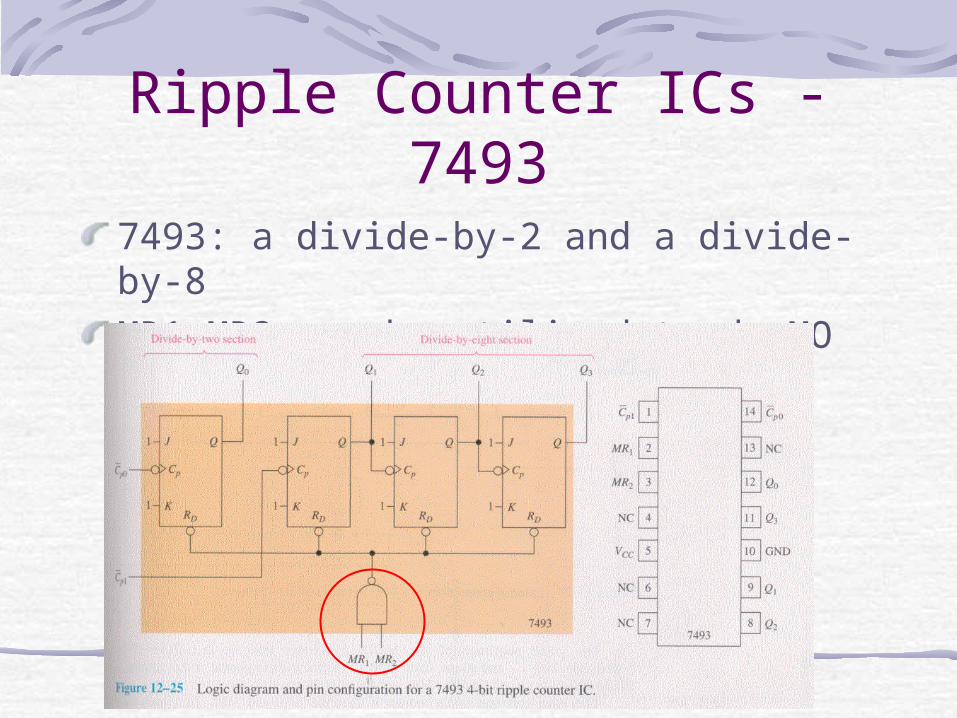
Ripple Counter ICs - 74937493: a divide-by-2 and a divide-by-8MR1,MR2 can be utilized to do MOD-N.
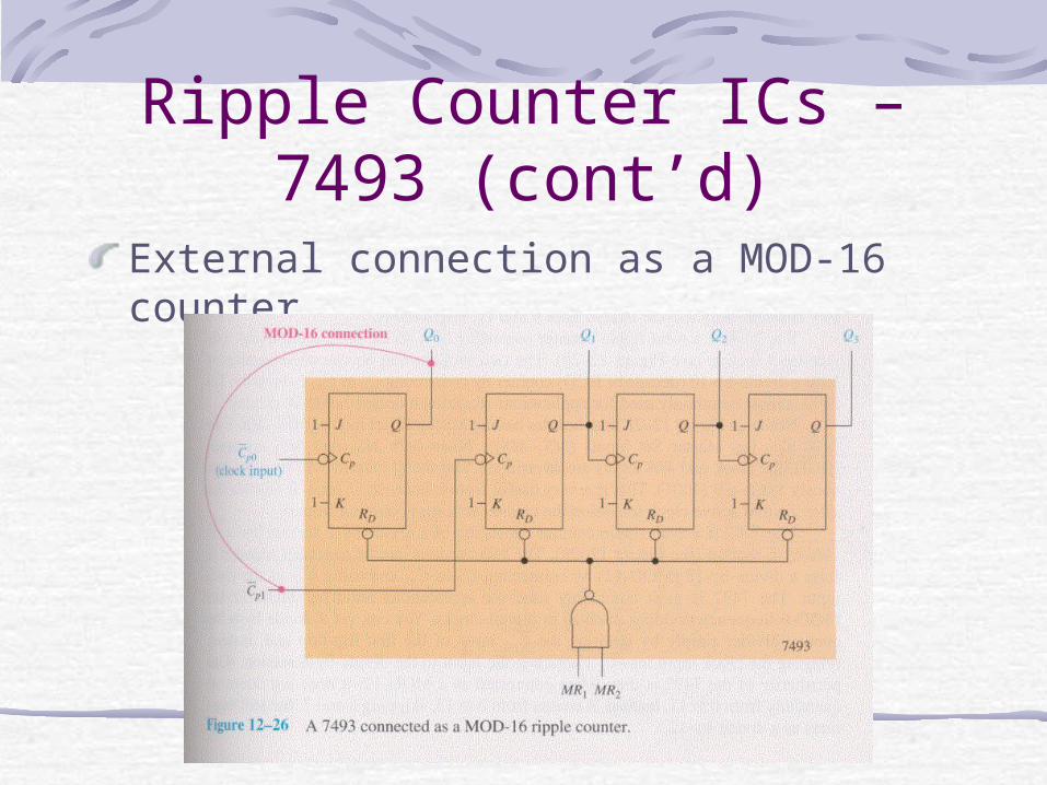
Ripple Counter ICs – 7493 (cont’d)
External connection as a MOD-16 counter.
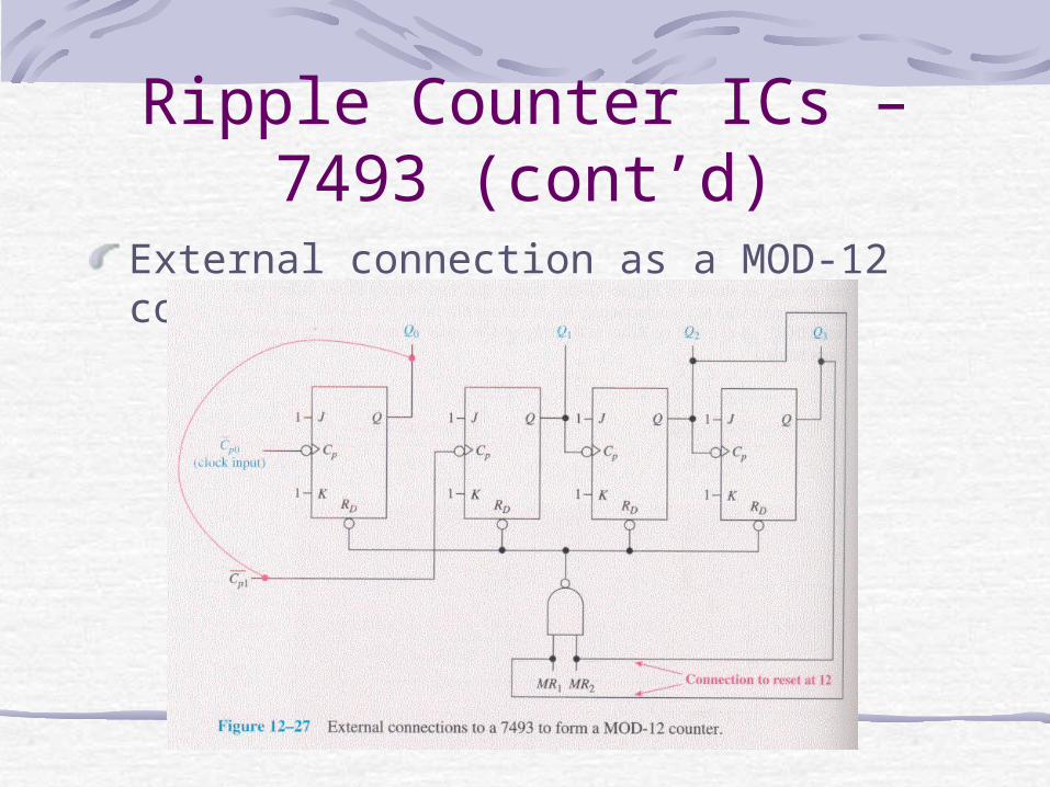
Ripple Counter ICs – 7493 (cont’d)
External connection as a MOD-12 counter.
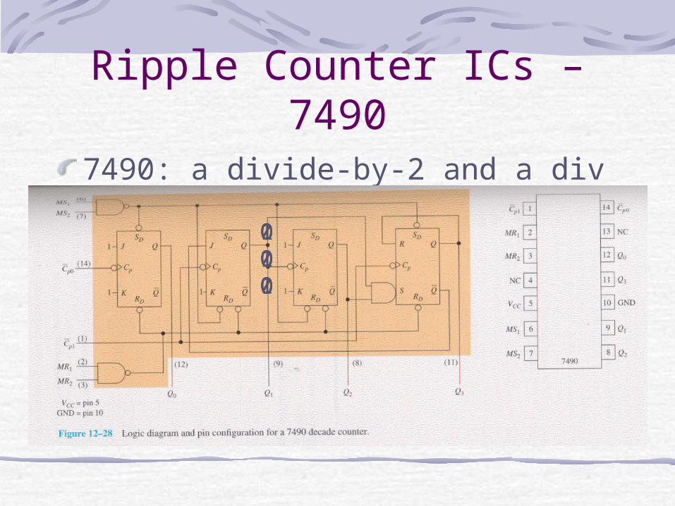
Ripple Counter ICs – 74907490: a divide-by-2 and a divide-by-5.
0 0 01 0 00 1 01 1 00 0 10 0 0
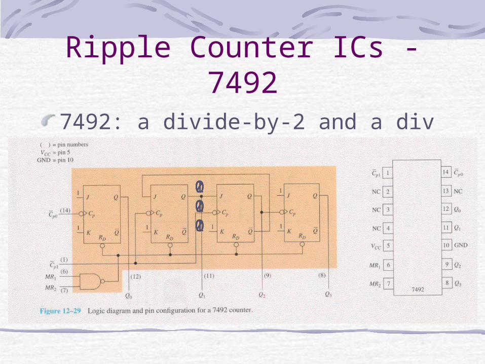
Ripple Counter ICs - 74927492: a divide-by-2 and a divide-by-6.
0 0 01 0 00 1 00 0 11 0 10 1 10 0 0
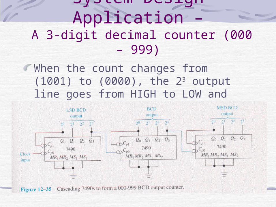
System Design Application –
A 3-digit decimal counter (000 – 999)
When the count changes from (1001) to (0000), the 23 output line goes from HIGH to LOW and trigger the next counter.
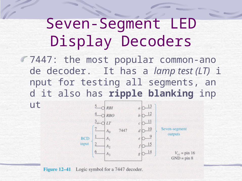
Seven-Segment LED Display Decoders
7447: the most popular common-anode decoder. It has a lamp test (LT) input for testing all segments, and it also has ripple blanking input and output (RBI,RBO).
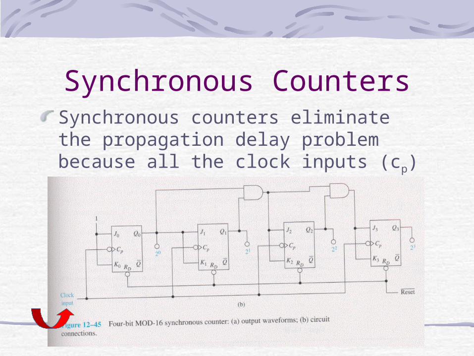
Synchronous CountersSynchronous counters eliminate the propagation delay problem because all the clock inputs (cp) are tied to a common clock.
Synchronous Counters(cont’d)
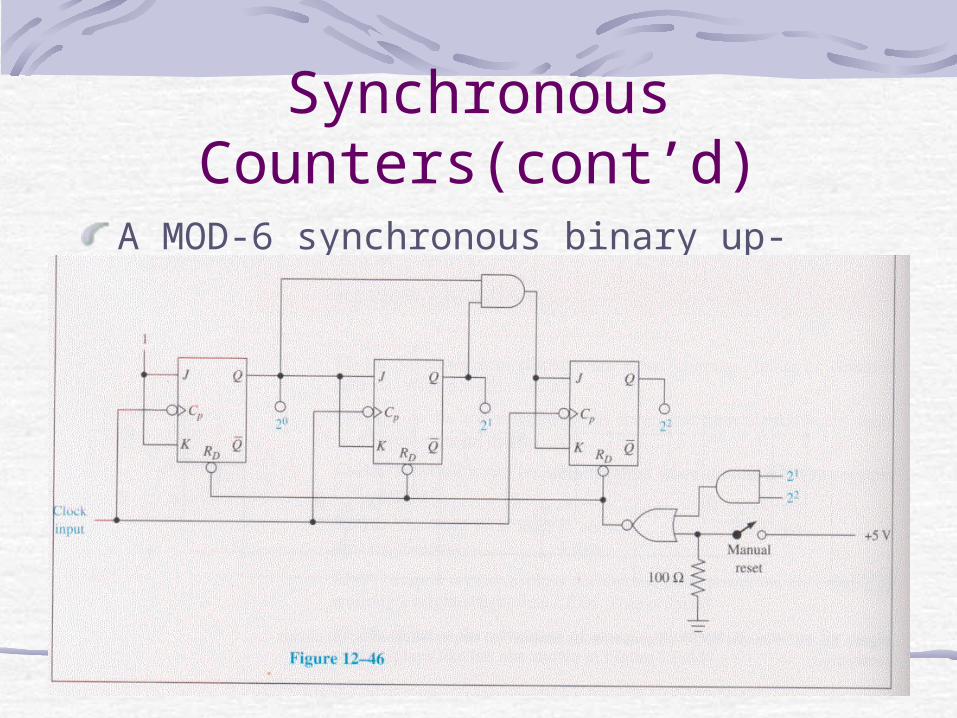
A MOD-6 synchronous binary up-counter.
Synchronous Up/Down-Counter ICs
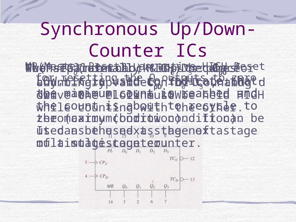
MR(Master Reset): an active-HIGH Reset for resetting the Q outputs to zero.
PL(Parallel Load) & D0~D3: place any binary value on D0~D3 , and drive the PL line LOW.
Two separate clock inputs: CpU for counting up and CpD for counting down. One clock must be held HIGH while counting with the other.
When TCU(normally HIGH) becomes LOW, it is used to indicate that the maximum count is reached and the count is about to recycle to zero(carry condition). It can be used as the next stage of a multistage counter.
When TCD(normally HIGH) becomes LOW, it is used to indicate that the minimum count is reached and the count is about to recycle to the maximum(borrow condition). It can be used as the next stage of a multistage counter.
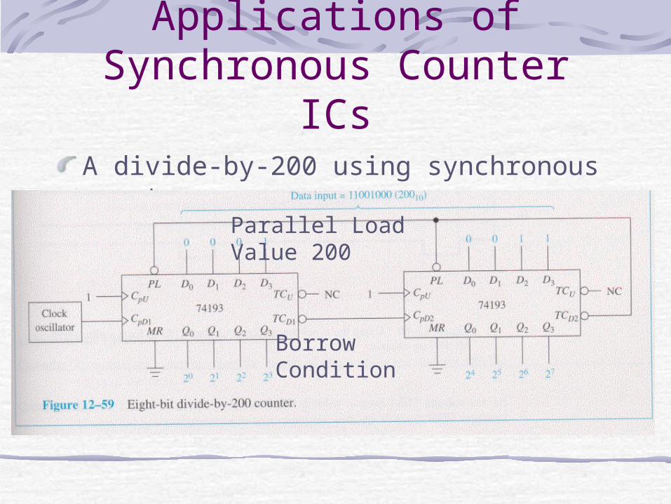
Applications of Synchronous Counter ICsA divide-by-200 using synchronous counters.
Borrow Condition
Parallel Load Value 200