Embed Size (px)
Citation preview
Data sheet
Counterbalance Valve BVE RE 95525/11.11 1/12
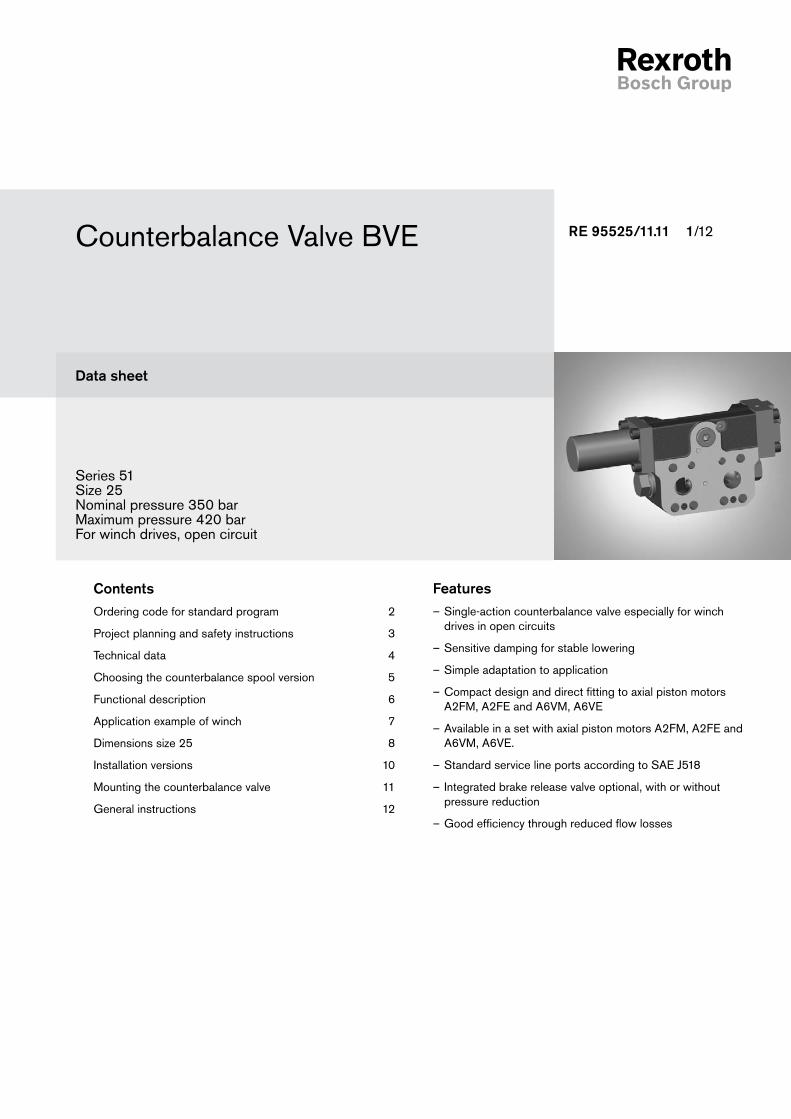
Series 51Size 25Nominal pressure 350 barMaximum pressure 420 barFor winch drives, open circuit
FeaturesSingle-action counterbalance valve especially for winch –drives in open circuits
Sensitive damping for stable lowering –
Simple adaptation to application –
Compact design and direct fitting to axial piston motors –A2FM, A2FE and A6VM, A6VE
Available in a set with axial piston motors A2FM, A2FE and –A6VM, A6VE.
Standard service line ports according to SAE J518 –
Integrated brake release valve optional, with or without –pressure reduction
Good efficiency through reduced flow losses –
ContentsOrdering code for standard program 2
Project planning and safety instructions 3
Technical data 4
Choosing the counterbalance spool version 5
Functional description 6
Application example of winch 7
Dimensions size 25 8
Installation versions 10
Mounting the counterbalance valve 11
General instructions 12
2/12 Bosch Rexroth AG Counterbalance Valve BVE Series 51 RE 95525/11.11
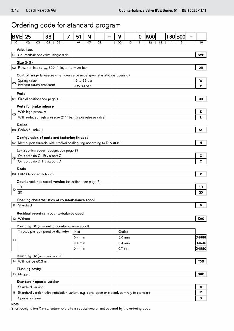
Valve type01 Counterbalance valve, single-side BVE
Size (NG)02 Flow, nominal qv nom 320 l/min, at Δp = 20 bar 25
Control range (pressure when counterbalance spool starts/stops opening)
03Spring value (without return pressure)
18 to 38 bar W
9 to 39 bar V
Ports04 Size allocation: see page 11 38
Ports for brake release
05With high pressure S
With reduced high pressure 21+4 bar (brake release valve) L
Series06 Series 5, index 1 51
Configuration of ports and fastening threads07 Metric, port threads with profiled sealing ring according to DIN 3852 N
Long spring cover (design: see page 8)
08On port side C, lift via port C C
On port side D, lift via port D C
Seals09 FKM (fluor-caoutchouc) V
Counterbalance spool version (selection: see page 5)
1010 10
20 20
Opening characteristics of counterbalance spool11 Standard 0
Residual opening in counterbalance spool12 Without K00
Damping D1 (channel to counterbalance spool)
13
Throttle pin, comparative diameter Inlet Outlet
0.4 mm 2.0 mm D4599
0.4 mm 0.4 mm D4545
0.4 mm 0.7 mm D4580
Damping D2 (reservoir outlet)14 With orifice ø0.3 mm T30
Flushing cavity15 Plugged S00
Standard / special version
16
Standard version 0
Standard version with installation variant, e.g. ports open or closed, contrary to standard Y
Special version S
NoteShort designation X on a feature refers to a special version not covered by the ordering code.
BVE 25 38 / 51 N – V 0 K00 T30 S00 –01 02 03 04 05 06 07 08 09 10 11 12 13 14 15 16
Ordering code for standard program
RE 95525/11.11 Counterbalance Valve BVE Series 51 Bosch Rexroth AG 3/12
Order detailsWhen placing the order, the following information is necessary to ensure correct acceptance at our test stands:
Motor ordering code –
Counterbalance valve ordering code –
Flow –
Application (e.g winch) –
Pressure setting of the secondary pressure relief valves in –the motor
For the design of the brake release valve, we must know –the following data for the mechanical park brake:
the cracking pressure -
the volume of the counterbalance spool between minimum -stroke (brake closed) and maximum stroke (brake released with 21 bar)
the required closing time for a warm device (oil viscosity -approx. 15 mm2/s)
Counterbalance valve and axial piston motor can be ordered as a ready-assembled and tested unit.
Type selection (ordering code)Control rangeThe control range defines the pressure range at which the counterbalance spool starts to open.
The control range of the counterbalance spool is to be chosen so that the mechanical park brake is fully open before the coun-terbalance spool starts to open.
Brake releaseThe integrated pressure reduction valve is necessary when the mechanical brake on the gear unit cannot handle the full system pressure.
The maximum permissible brake release pressure must be agreed with the winch manufacturer. The brake release valve reduces the high pressure to the value stated.
Counterbalance spool versionThe counterbalance spool version depends on the maximum flow required through the counterbalance valve.
Counterbalance spool selection for required flow as per dia-gram on page 5.
If the desired flow is not within the range of the counterbalance spool supplied, please contact us.
Residual opening in counterbalance spoolIn winch applications, any residual opening is prohibited, since otherwise the load would not stay suspended. For that reason, version "K00" is prescribed.
Project planning and safety instructionsDampingThe throttle pin from D1 (inlet) and the orifice D2, plus the return pressure to the reservoir, define the actual cracking pressure of the counterbalance spool in MP1.
The damping D1 (outlet) and D2 define the closing speed of the counterbalance spool. The larger the comparative diameter D1 (outlet), the faster the counterbalance spool will close (see table on page 4).
For the initial equipment (prototype), we recommend damping D1 = D4599 and D2 = T30.
Safety instructionsFailure to observe any of the following points can lead to un-controlled operating conditions with serious personal injury and material damage.
The counterbalance valve does – not replace the mechanical park brake. If necessary, provide mechanical brake systems.
Counterbalance valves are usually only used in open circuits. –
System optimization (reduction) for the first prototype is rec- –ommended with regard to the valve block, axial piston motor, counterbalance valve and park brake.
The opening and closing characteristics of the counterbal- –ance valve and control piston in the directional valve must be mutually compatible.
The mechanical park brake in winch drives must only be –effective after the counterbalance valve spool has closed. Otherwise, the brake will be subject to wear.
Note the maximum permissible cracking pressure of the park –brake. If necessary, use the integrated pressure reduction valve as a brake release valve with reduced high pressure (version "L").
The counterbalance valve converts the entire kinetic en- –ergy/potential energy into heat during the braking/lowering process. Consequently, ensure sufficient cooler and/or tank capacity.
Counterbalance valves should only be operated in combina- –tion with close-by secondary pressure relief valves in order to protect the motor against pressure spikes. The table on page 11 lists the motor and port plate types for the counter-balance valve BVE25. The port plates already contain the secondary pressure-relief valves.
Feeding at port S of the counterbalance valve reduces the –risk of cavitation. Ensure sufficient pressure and flow for feeding.
We recommend ordering an axial piston motor and counter- –balance valve as a single unit. This ensures optimal matching and combined testing.
If motor and counterbalance valve are ordered separately, –we recommend that you consult our application engineers for the appropriate motor version.
Further safety-relevant measures for the application must be added as necessary by the customer.

4/12 Bosch Rexroth AG Counterbalance Valve BVE Series 51 RE 95525/11.11
Technical dataHydraulic fluidThe axial piston motor used is decisive for the choice of hy-draulic fluid. Further information should be taken from our data sheets dur-ing project planning.
Operating pressure range
Pressure at service line port C or D
Nominal pressure pnom _________________ 350 bar absolute
Maximum pressure pmax _______________ 420 bar absolute Single operating period ____________________________ 10 s Total operating period ____________________________ 300 h
Definition
Nominal pressure pnom
The nominal pressure corresponds to the maximum design pressure.
Maximum pressure pmax
The maximum pressure corresponds to the maximum operat-ing pressure within the single operating period. The sum of the single operating periods must not exceed the total operating period.
Identification of cracking pressure p1 (value without return pressure)
The throttle chain from D1 and D2 is used to damp the opening and closing speeds of the counterbalance spool. The actual working pressure, measured at MP1, is reduced by the throttle chain from D1 and D2 and actuates the counterbalance spool. The dependence of the actual pressure value at MP1 for the opening of the counterbalance spool on the cross-sectional area of the orifice at D1 and D2 is stated in the table below.
Schematic
MP1
VGVF
S
Gext
Mk
D
C
D´
C´
G´
L´
D1
D2
Lower
Lift
Short cover
Port side
Counterbalance spool
OutletInlet
Motor side
Table of values (theoretical values, without efficiency and tolerances; values rounded)
Size NG BVE.W BVE.V
Operating pressure p bar Nominal pressure
350 350
Maximum pressure
420 420
Flow, nominal, at Δp = 20 bar qv max L/min 320 320
Start of opening of counterbalance spool at port Mk ΔpK B bar 18 9
End of opening of counterbalance spool at port Mk ΔpK E bar 38 39
Pressure reduction valve for brake release (fixed values)
Maximum control pressure
p bar BVE...L/ 21+4 21+4
Start of control p bar BVE...L/ 10+4 10+4
Mass approx. m kg 18 18
Cracking pressure p1
Pressure value at counterbalance spool Pressure value at port MP1
Pres-sure spring
Throttle pin in inlet channel D1
Orifice in reservoir outlet D2
Start of opening ΔpK B [bar] (approx.)
End of opening ΔpK E [bar] (approx.)
Start of opening Δp1 [bar] (approx.)
End of opening Δp1 [bar] (approx.)
W 0.45 0.3 18 38 24 51
V 0.45 0.3 9 39 12 52
RE 95525/11.11 Counterbalance Valve BVE Series 51 Bosch Rexroth AG 5/12
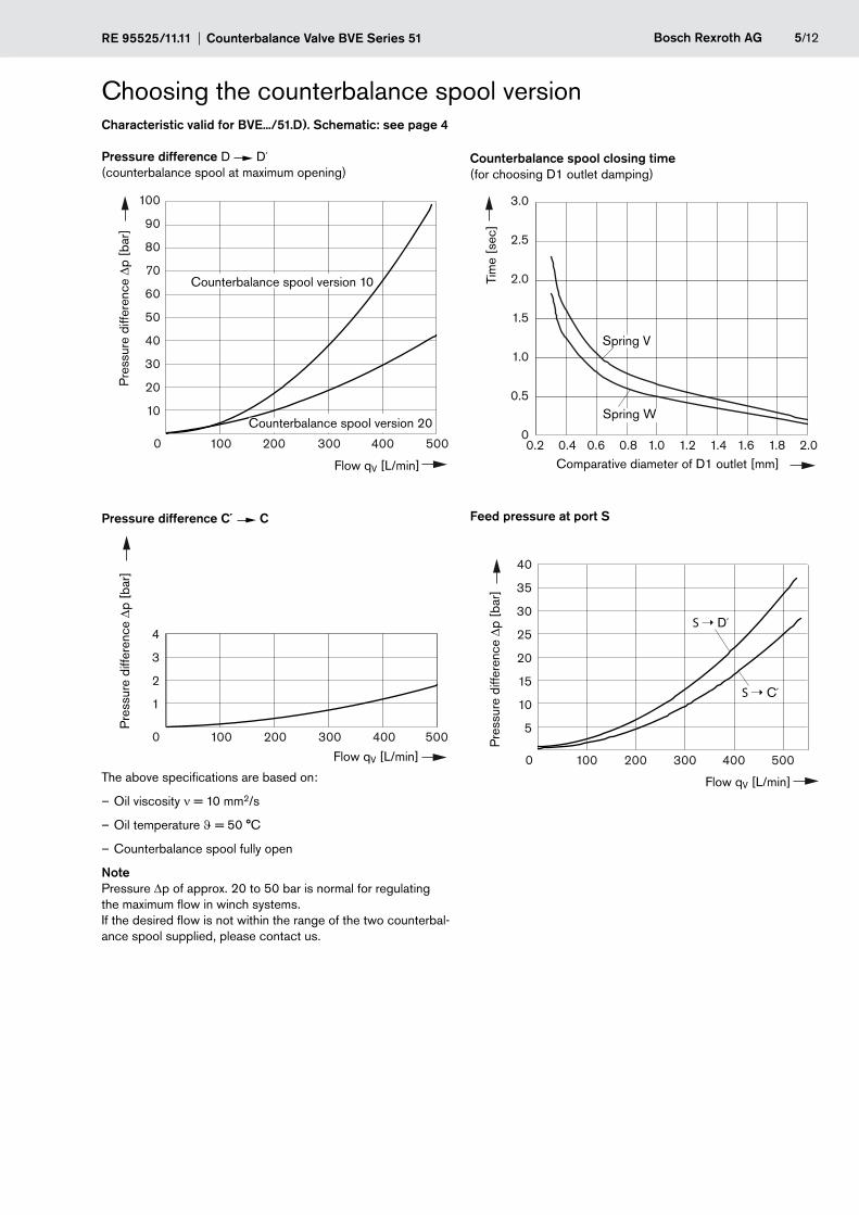
Choosing the counterbalance spool versionCharacteristic valid for BVE.../51.D). Schematic: see page 4
Pressure difference D D´ (counterbalance spool at maximum opening)
0 100 200 300 400 500
100
90
80
70
60
50
40
30
20
10
Flow qV [L/min]
Pre
ssur
e di
ffere
nce Δp
[ba
r]
Counterbalance spool version 10
Counterbalance spool version 20
Pressure difference C´ C
0 100 200 300 400 500
4
3
2
1
Flow qV [L/min]
Pre
ssur
e di
ffere
nce Δp
[ba
r]
The above specifications are based on:
Oil viscosity – ν = 10 mm2/s
Oil temperature – ϑ = 50 °C
Counterbalance spool fully open –
NotePressure Δp of approx. 20 to 50 bar is normal for regulating the maximum flow in winch systems. If the desired flow is not within the range of the two counterbal-ance spool supplied, please contact us.
Counterbalance spool closing time (for choosing D1 outlet damping)
0.2 0.4 0.6 0.8 1.0 1.2 1.4 1.6 1.8 2.0
3.0
2.5
2.0
1.5
1.0
0.5
0
Tim
e [s
ec]
Comparative diameter of D1 outlet [mm]
Spring W
Spring V
Feed pressure at port S
0 100 200 300 400 500
40
35
30
25
20
15
10
5
S ➝ C´
S ➝ D´
Flow qV [L/min]
Pre
ssur
e di
ffere
nce Δp
[ba
r]
6/12 Bosch Rexroth AG Counterbalance Valve BVE Series 51 RE 95525/11.11
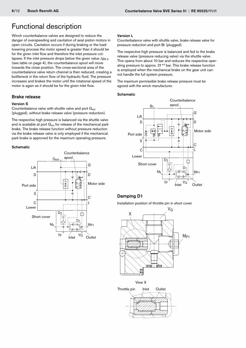
Functional descriptionWinch counterbalance valves are designed to reduce the danger of overspeeding and cavitation of axial piston motors in open circuits. Cavitation occurs if during braking or the load-lowering process the motor speed is greater than it should be for the given inlet flow and therefore the inlet pressure col-lapses. If the inlet pressure drops below the given value ΔpK E (see table on page 4), the counterbalance spool will move towards the close position. The cross-sectional area of the counterbalance valve return channel is then reduced, creating a bottleneck in the return flow of the hydraulic fluid. The pressure increases and brakes the motor until the rotational speed of the motor is again as it should be for the given inlet flow.
Brake releaseVersion SCounterbalance valve with shuttle valve and port Gext (plugged), without brake release valve (pressure reduction).
The respective high pressure is balanced via the shuttle valve and is available at port Gext for release of the mechanical park brake. The brake release function without pressure reduction via the brake release valve is only employed if the mechanical park brake is approved for the maximum operating pressure.
Schematic
Lower
Lift
Port side
MP1
VGVF
S
Gext
Mk
D
C
D´
C´
G´
L´
D1
D2Short cover
Counterbalance spool
OutletInlet
Motor side
Version LCounterbalance valve with shuttle valve, brake release valve for pressure reduction and port Br (plugged).
The respective high pressure is balanced and fed to the brake release valve (pressure reducing valve) via the shuttle valve. This opens from about 10 bar and reduces the respective oper-ating pressure to approx. 21+4 bar. This brake release function is employed when the mechanical brake on the gear unit can-not handle the full system pressure.
The maximum permissible brake release pressure must be agreed with the winch manufacturer.
Schematic
MP1
VGVF
S
Br
Mk
D
C
D´
C´
G´
L´
D1
D2Lower
Lift
Port side
Short cover
Counterbalance spool
OutletInlet
Motor side
Damping D1Installation position of throttle pin in short cover
MP1
VGX
View X
Inlet OutletThrottle pin
RE 95525/11.11 Counterbalance Valve BVE Series 51 Bosch Rexroth AG 7/12
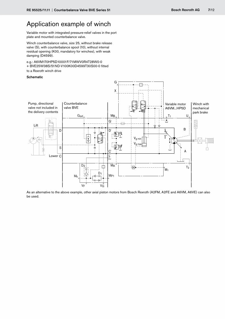
Application example of winchVariable motor with integrated pressure-relief valves in the port plate and mounted counterbalance valve.
Winch counterbalance valve, size 25, without brake release valve (S), with counterbalance spool (10), without internal residual opening (K00, mandatory for winches), with weak damping (D4599).
e.g.: A6VM170HP5D10001F/71MWV0R4T28W0-0 + BVE25W38S/51ND-V100K00D4599T30S00-0 fitted to a Rexroth winch drive
Schematic
T2
T1
M1
Vg min
Vg max
B
A
G
X
U
MP1
VGVF
S
Gext
Mk
D
C
D´
C´
G´
L´
D1
D2
MB
MA
Lower
Lift
Pump, directional valve not included in the delivery contents
Variable motor A6VM...HP5D
Winch with mechanical park brake
Counterbalance valve BVE
As an alternative to the above example, other axial piston motors from Bosch Rexroth (A2FM, A2FE and A6VM, A6VE) can also be used.
8/12 Bosch Rexroth AG Counterbalance Valve BVE Series 51 RE 95525/11.11
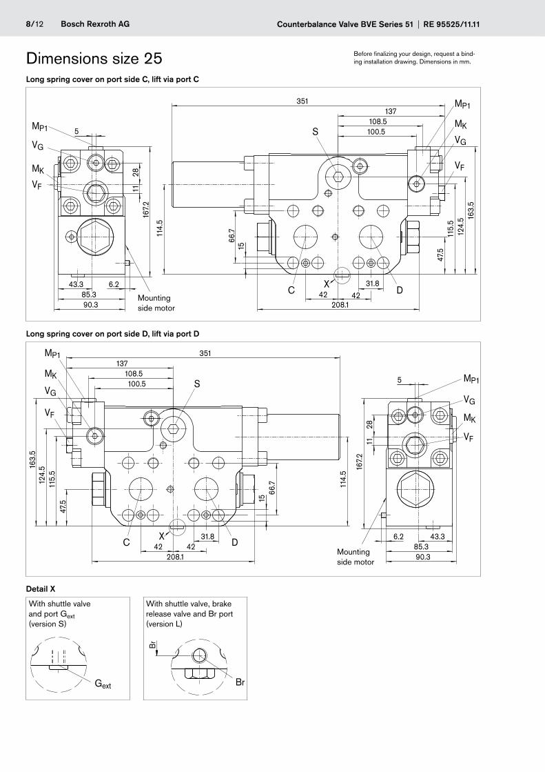
Before finalizing your design, request a bind-ing installation drawing. Dimensions in mm.Dimensions size 25
Long spring cover on port side C, lift via port C
100.5108.5
137351
S
MP1
VG
MK
47.5
163.
5
115.
512
4.5
VF
31.84242
208.1
DCX
1566
.7114.
5
43.385.390.3
6.2
167.
228
115MP1
VG
MK
VF
Mounting side motor
Long spring cover on port side D, lift via port D
167.
2
528
11
43.385.390.3
6.2
100.5108.5
137351
47.5
163.
5
1566
.7
31.84242
208.1
S
DC
MP1
MK
VG
VF
114.
5
115.
512
4.5
MP1
MK
VG
VF
XMounting side motor
Detail X
With shuttle valve and port Gext (version S)
With shuttle valve, brake release valve and Br port (version L)
Gext Br
Br

RE 95525/11.11 Counterbalance Valve BVE Series 51 Bosch Rexroth AG 9/12
Dimensions size 25Ports with profiled sealing ring (ordering code designation N)Designation Port for Standard Size1) Maximum
pressure [bar]2)State
C, D Service line SAE J5183) 1 1/4 in 420 O
Fastening thread C/D DIN 13 M14 x 2; 19 deep
S Infeed DIN 3852 M27 x 2; 16 deep 5) X
Br Brake release, reduced high pressure DIN 3852M12 x 1.5; 12.5 deep
8 X
Gext Brake release, high pressure DIN 3852 M12 x 1.5; 12 deep 420 X
C´, D´ Service channel to motor4) ø30 420 O
G´ Selected high pressure, channel to motor4) ø4.2 420 O
L´ Leakage channel to motor4) ø4.2 10 O
MP1 Measuring pressure A, before filter DIN 3852 M14 x 1.5; 12 deep 420 X
VG Plug for threaded channel4) DIN 3852 M14 x 1.5; 12 deep 420 X
VF Threaded plug for filter channel4) DIN 6149 M16 x 1.5; 13 deep 420 X
MK Measuring pressure at counterbalance spool DIN 3852 M14 x 1.5; 12 deep 420 X
O-ring for sealing to axial piston motor
C´, D´ Service line port AS 568 A 37.69 x 3.53 (-S-FKM90)
G´ Selected high-pressure channel for HA control of A6VM motor
DIN 3771 9 x 2 (-N-V80G1)
L´ Leakage channel DIN 3771 9 x 2 (-N-V80G1)
Observe the general instructions on page 12 for the maximum tightening torques.1)
Momentary pressure spikes may occur depending on the application. Keep this in mind when selecting measuring devices and 2)
fittings.Only dimensions according to SAE J518, 3) metric fastening thread is a deviation from standard.No customer ports. Subject to technical change4)
Application-specific. Please contact us5)
O = Must be connected (plugged on delivery) X = Plugged (in normal operation)
Before finalizing your design, request a bind-ing installation drawing. Dimensions in mm.
10/12 Bosch Rexroth AG Counterbalance Valve BVE Series 51 RE 95525/11.11
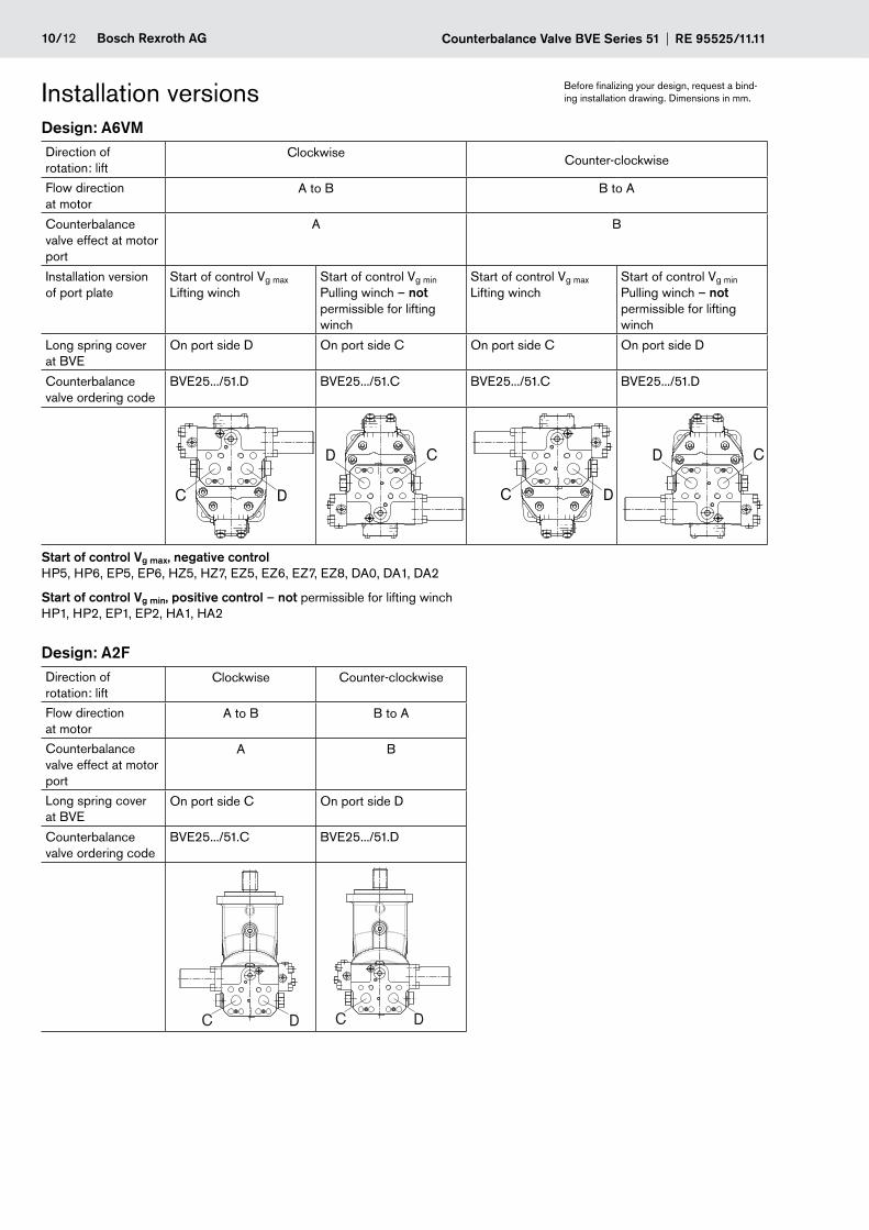
Design: A6VMDirection of rotation: lift
Clockwise Counter-clockwise
Flow direction at motor
A to B B to A
Counterbalance valve effect at motor port
A B
Installation version of port plate
Start of control Vg max Lifting winch
Start of control Vg min Pulling winch – not permissible for lifting winch
Start of control Vg max Lifting winch
Start of control Vg min Pulling winch – not permissible for lifting winch
Long spring cover at BVE
On port side D On port side C On port side C On port side D
Counterbalance valve ordering code
BVE25.../51.D BVE25.../51.C BVE25.../51.C BVE25.../51.D
DC
D C
DC
D C
Start of control Vg max, negative controlHP5, HP6, EP5, EP6, HZ5, HZ7, EZ5, EZ6, EZ7, EZ8, DA0, DA1, DA2
Start of control Vg min, positive control – not permissible for lifting winchHP1, HP2, EP1, EP2, HA1, HA2
Design: A2F Direction of rotation: lift
Clockwise Counter-clockwise
Flow direction at motor
A to B B to A
Counterbalance valve effect at motor port
A B
Long spring cover at BVE
On port side C On port side D
Counterbalance valve ordering code
BVE25.../51.C BVE25.../51.D
DC DC
Before finalizing your design, request a bind-ing installation drawing. Dimensions in mm.Installation versions
RE 95525/11.11 Counterbalance Valve BVE Series 51 Bosch Rexroth AG 11/12
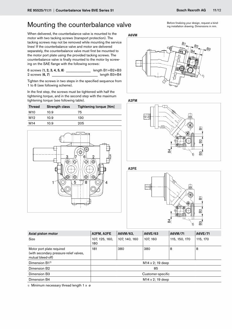
Before finalizing your design, request a bind-ing installation drawing. Dimensions in mm.Mounting the counterbalance valve
When delivered, the counterbalance valve is mounted to the motor with two tacking screws (transport protection). The tacking screws may not be removed while mounting the service lines! If the counterbalance valve and motor are delivered separately, the counterbalance valve must first be mounted to the motor port plate using the provided tacking screws. The counterbalance valve is finally mounted to the motor by screw-ing on the SAE flange with the following screws:
6 screws (1, 2, 3, 4, 5, 8) ______________ length B1+B2+B3 2 screws (6, 7) __________________________ length B3+B4
Tighten the screws in two steps in the specified sequence from 1 to 8 (see following scheme).
In the first step, the screws must be tightened with half the tightening torque, and in the second step with the maximum tightening torque (see following table).
Thread Strength class Tightening torque [Nm]
M10 10.9 75
M12 10.9 130
M14 10.9 205
1
23
45
67
8
A6VM
1)
B1 B2B3B4
A2FM
B1
B2
B4
B3
1)
A2FE
B1
B2
B4
B3
1)
Axial piston motor A2FM, A2FE A6VM/63, A6VE/63 A6VM/71 A6VE/71
Size 107, 125, 160, 180
107, 140, 160 107, 160 115, 150, 170 115, 170
Motor port plate required (with secondary pressure-relief valves, mutual bleed-off)
181 380 380 8 8
Dimension B11) M14 x 2; 19 deep
Dimension B2 85
Dimension B3 Customer-specific
Dimension B4 M14 x 2; 19 deep
Minimum necessary thread length 1 x ø1)
12/12 Bosch Rexroth AG Counterbalance Valve BVE Series 51 RE 95525/11.11
© This document, as well as the data, specifications and other information set forth in it, are the exclusive property of Bosch Rexroth AG. It may not be repro-duced or given to third parties without its consent.
The data specified above only serve to describe the product. No statements concerning a certain condition or suitability for a certain application can be de-rived from our information. The information given does not release the user from the obligation of own judgment and verification. It must be remembered that our products are subject to a natural process of wear and aging.
Subject to change.
Bosch Rexroth AG Axial piston unitsGlockeraustraße 289275 Elchingen, GermanyTel.: +49-7308-82-0Fax: [email protected]/axial-piston-motors
General instructionsThe BVE counterbalance valve is – designed to be used in an open circuit.
The project planning, installation and commissioning of the axial piston unit requires the involvement of qualified personnel. –
Before using the counterbalance valve, please read the corresponding instruction manual completely and thoroughly. If neces- –sary, these can be requested from Bosch Rexroth.
During and shortly after operation, there is a risk of burns on the counterbalance valve and the axial piston unit. Take appropriate –safety measures (e.g. by wearing protective clothing).
Depending on the operating conditions of the counterbalance valve (operating pressure, fluid temperature), the characteristic –may shift.
Service line ports: –
The ports and fastening threads are designed for the specified maximum pressure - of the counterbalance valve. The machine or system manufacturer must ensure that the connecting elements and lines correspond to the specified operating conditions (pressure, flow, hydraulic fluid, temperature) with the necessary safety factors.
The service line ports and function ports can only be used to accommodate hydraulic lines. -
The data and notes contained herein must be adhered to. –
The product is not approved as a component for the safety concept of a general machine according to ISO 13849. –
The following tightening torques apply: –
Fittings: -Observe the manufacturer's instructions regarding the tightening torques of the fittings used.
Mounting bolts: -For mounting bolts with metric ISO thread according to DIN 13, we recommend checking the tightening torque in individual cases in accordance with VDI 2230.
Female threads of the counterbalance valve or axial piston unit: -The maximum permissible tightening torques MG max are maximum values of the female threads and must not be exceeded. For values, see the following table.
Threaded plugs: -For the metallic threaded plugs supplied with the counterbalance valve or axial piston unit, the required tightening torques of threaded plugs MV apply. For values, see the following table.
Ports Maximum permissible tightening torque of the female threads MG max
Required tightening torque of the threaded plugs MV
1)
WAF hexagon socket of the threaded plugsStandard Size of thread
ISO 3852 M12 x 1.5 50 Nm 25 Nm2) 6 mm
M14 x 1.5 80 Nm 35 Nm 6 mm
M27 x 2 330 Nm 135 Nm 12 mm
The tightening torques apply for screws in the “dry” state as received on delivery and in the “lightly oiled” state for installation.1)
In the “lightly oiled” state, the 2) MV is reduced to 17 Nm for M12 x 1.5.