Embed Size (px)
Citation preview
Seen on a T-shirt:
There are 10 kinds ofpeople - those whounderstand binary,and those who don't.
Logic states True False
1 0High Low+Vs 0VOn Off
Home | Map | Projects | Construction | Soldering | Study | Components | 555 | Symbols |FAQ | Links
Counting CircuitsBinary | 4-bit | BCD | Counters | Ripple/Synchronous | Reset |Freq. division | Decoders | Display drivers | Linking counters
Next Page: Quantities and UnitsAlso See: 4000 series ICs | 74 series ICs | Logic Gates
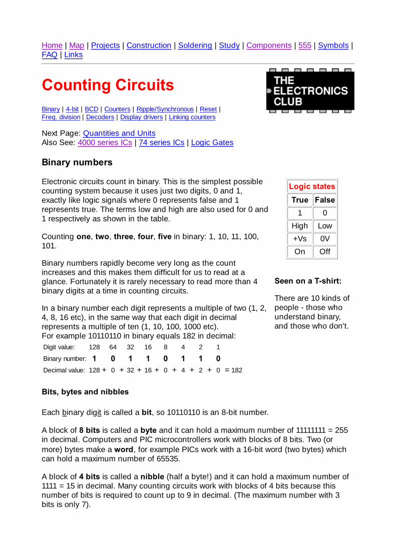
Binary numbers
Electronic circuits count in binary. This is the simplest possiblecounting system because it uses just two digits, 0 and 1,exactly like logic signals where 0 represents false and 1represents true. The terms low and high are also used for 0 and1 respectively as shown in the table.
Counting one, two, three, four, five in binary: 1, 10, 11, 100,101.
Binary numbers rapidly become very long as the countincreases and this makes them difficult for us to read at aglance. Fortunately it is rarely necessary to read more than 4binary digits at a time in counting circuits.
In a binary number each digit represents a multiple of two (1, 2,4, 8, 16 etc), in the same way that each digit in decimalrepresents a multiple of ten (1, 10, 100, 1000 etc).For example 10110110 in binary equals 182 in decimal:Digit value: 128 64 32 16 8 4 2 1
Binary number: 1 0 1 1 0 1 1 0Decimal value: 128 + 0 + 32 + 16 + 0 + 4 + 2 + 0 = 182
Bits, bytes and nibbles
Each binary digit is called a bit, so 10110110 is an 8-bit number.
A block of 8 bits is called a byte and it can hold a maximum number of 11111111 = 255in decimal. Computers and PIC microcontrollers work with blocks of 8 bits. Two (ormore) bytes make a word, for example PICs work with a 16-bit word (two bytes) whichcan hold a maximum number of 65535.
A block of 4 bits is called a nibble (half a byte!) and it can hold a maximum number of1111 = 15 in decimal. Many counting circuits work with blocks of 4 bits because thisnumber of bits is required to count up to 9 in decimal. (The maximum number with 3bits is only 7).
BinaryD C B A
Decimal Hexbase 16
0 0 0 00 0 0 10 0 1 00 0 1 10 1 0 00 1 0 10 1 1 00 1 1 11 0 0 01 0 0 11 0 1 01 0 1 11 1 0 01 1 0 11 1 1 01 1 1 1
0123456789101112131415
0123456789ABCDEF
A square wave clock signal
Hexadecimal (base 16)
Hexadecimal (often just called 'hex') is base 16 counting with 16 digits. It starts with thedecimal digits 0-9, then continues with letters A (10), B (11), C (12), D (13), E (14) and F(15). Each hexadecimal digit is equivalent to 4 binary digits, making conversion betweenthe two systems relatively easy. You may find hexadecimal used with PICs andcomputer systems but it is not generally used in simple counting circuits.
Example: 10110110 binary = B6 hexadecimal = 182 decimal.
Top of page | Binary | 4-bit | BCD | Counters | Ripple/Synchronous | Reset | Freq. division | Decoders |Display drivers | Linking
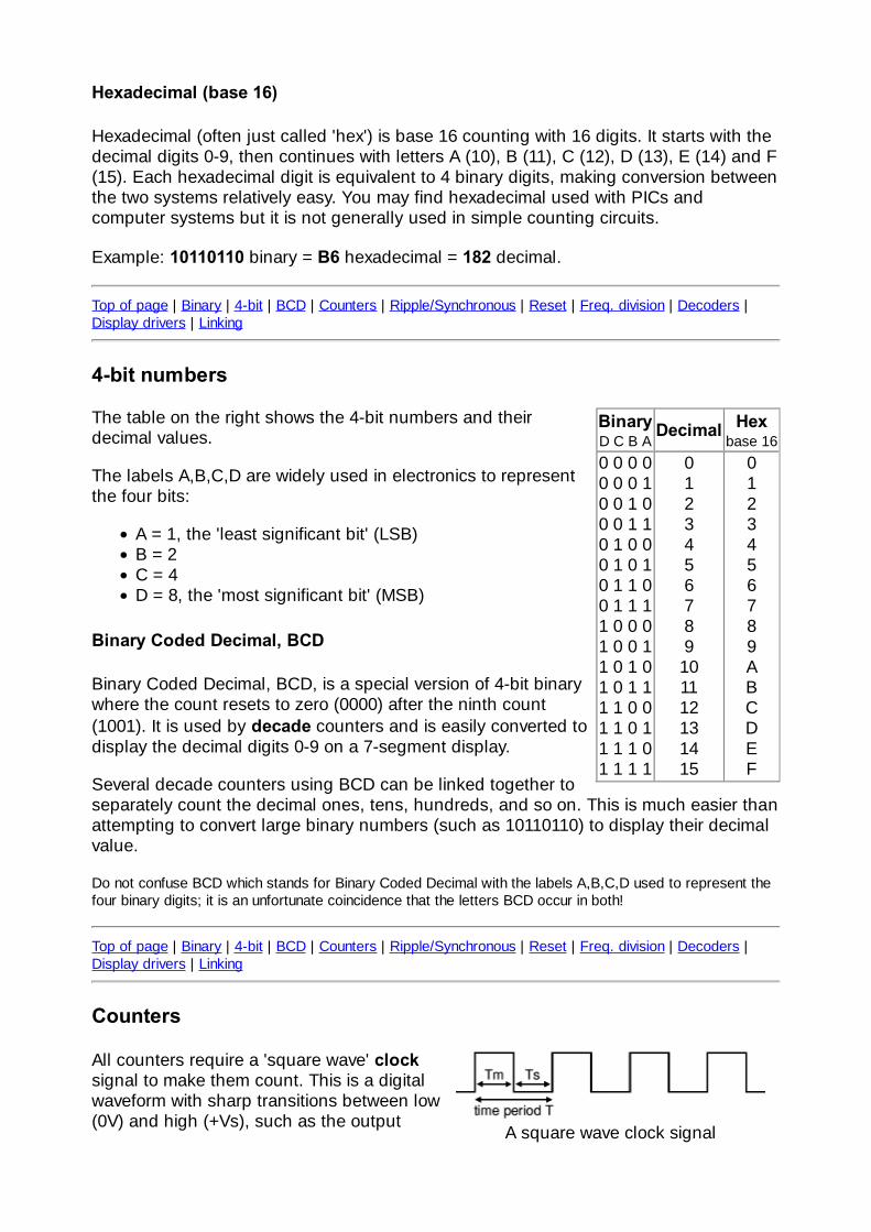
4-bit numbers
The table on the right shows the 4-bit numbers and theirdecimal values.
The labels A,B,C,D are widely used in electronics to representthe four bits:
A = 1, the 'least significant bit' (LSB)B = 2C = 4D = 8, the 'most significant bit' (MSB)
Binary Coded Decimal, BCD
Binary Coded Decimal, BCD, is a special version of 4-bit binarywhere the count resets to zero (0000) after the ninth count(1001). It is used by decade counters and is easily converted todisplay the decimal digits 0-9 on a 7-segment display.
Several decade counters using BCD can be linked together toseparately count the decimal ones, tens, hundreds, and so on. This is much easier thanattempting to convert large binary numbers (such as 10110110) to display their decimalvalue.
Do not confuse BCD which stands for Binary Coded Decimal with the labels A,B,C,D used to represent thefour binary digits; it is an unfortunate coincidence that the letters BCD occur in both!
Top of page | Binary | 4-bit | BCD | Counters | Ripple/Synchronous | Reset | Freq. division | Decoders |Display drivers | Linking
Counters
All counters require a 'square wave' clocksignal to make them count. This is a digitalwaveform with sharp transitions between low(0V) and high (+Vs), such as the output
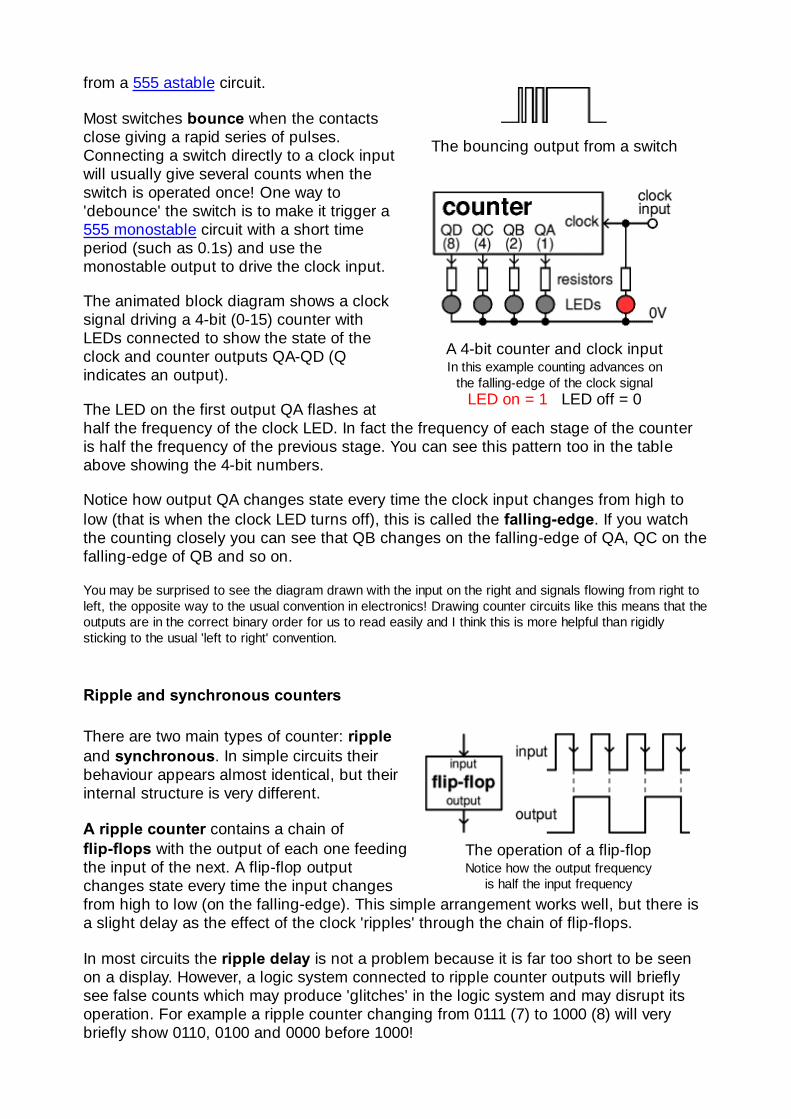
The bouncing output from a switch
A 4-bit counter and clock inputIn this example counting advances on
the falling-edge of the clock signalLED on = 1 LED off = 0
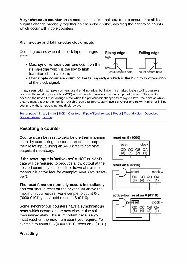
The operation of a flip-flopNotice how the output frequency
is half the input frequency
from a 555 astable circuit.
Most switches bounce when the contactsclose giving a rapid series of pulses.Connecting a switch directly to a clock inputwill usually give several counts when theswitch is operated once! One way to'debounce' the switch is to make it trigger a555 monostable circuit with a short timeperiod (such as 0.1s) and use themonostable output to drive the clock input.
The animated block diagram shows a clocksignal driving a 4-bit (0-15) counter withLEDs connected to show the state of theclock and counter outputs QA-QD (Qindicates an output).
The LED on the first output QA flashes athalf the frequency of the clock LED. In fact the frequency of each stage of the counteris half the frequency of the previous stage. You can see this pattern too in the tableabove showing the 4-bit numbers.
Notice how output QA changes state every time the clock input changes from high tolow (that is when the clock LED turns off), this is called the falling-edge. If you watchthe counting closely you can see that QB changes on the falling-edge of QA, QC on thefalling-edge of QB and so on.
You may be surprised to see the diagram drawn with the input on the right and signals flowing from right toleft, the opposite way to the usual convention in electronics! Drawing counter circuits like this means that theoutputs are in the correct binary order for us to read easily and I think this is more helpful than rigidlysticking to the usual 'left to right' convention.
Ripple and synchronous counters
There are two main types of counter: rippleand synchronous. In simple circuits theirbehaviour appears almost identical, but theirinternal structure is very different.
A ripple counter contains a chain offlip-flops with the output of each one feedingthe input of the next. A flip-flop outputchanges state every time the input changesfrom high to low (on the falling-edge). This simple arrangement works well, but there isa slight delay as the effect of the clock 'ripples' through the chain of flip-flops.
In most circuits the ripple delay is not a problem because it is far too short to be seenon a display. However, a logic system connected to ripple counter outputs will brieflysee false counts which may produce 'glitches' in the logic system and may disrupt itsoperation. For example a ripple counter changing from 0111 (7) to 1000 (8) will verybriefly show 0110, 0100 and 0000 before 1000!
A synchronous counter has a more complex internal structure to ensure that all itsoutputs change precisely together on each clock pulse, avoiding the brief false countswhich occur with ripple counters.
Rising-edge and falling-edge clock inputs
Counting occurs when the clock input changesstate.
Most synchronous counters count on therising-edge which is the low to hightransition of the clock signal.Most ripple counters count on the falling-edge which is the high to low transitionof the clock signal.
It may seem odd that ripple counters use the falling-edge, but in fact this makes it easy to link countersbecause the most significant bit (MSB) of one counter can drive the clock input of the next. This worksbecause the next bit must change state when the previous bit changes from high to low - the point at whicha carry must occur to the next bit. Synchronous counters usually have carry out and carry in pins for linkingcounters without introducing any ripple delays.
Top of page | Binary | 4-bit | BCD | Counters | Ripple/Synchronous | Reset | Freq. division | Decoders |Display drivers | Linking
Resetting a counter
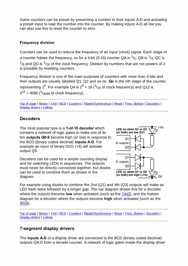
Counters can be reset to zero before their maximumcount by connecting one (or more) of their outputs totheir reset input, using an AND gate to combineoutputs if necessary.
If the reset input is 'active-low' a NOT or NANDgate will be required to produce a low output at thedesired count. If you see a line drawn above reset itmeans it is active low, for example: (say 'reset-bar').
The reset function normally occurs immediatelyand you should reset on the next count above themaximum you require. For example to count 0-5(0000-0101) you should reset on 6 (0110).
Some synchronous counters have a synchronousreset which occurs on the next clock pulse ratherthan immediately. This is important because youmust reset on the maximum count you require. Forexample to count 0-5 (0000-0101), reset on 5 (0101).
Presetting
Some counters can be preset by presenting a number to their inputs A-D and activatinga preset input to load the number into the counter. By making inputs A-D all low youcan also use this to reset the counter to zero.
Frequency division
Counters can be used to reduce the frequency of an input (clock) signal. Each stage ofa counter halves the frequency, so for a 4-bit (0-15) counter QA is 1/2, QB is 1/4, QC is1/8 and QD is 1/16 of the clock frequency. Division by numbers that are not powers of 2is possible by resetting counters.
Frequency division is one of the main purposes of counters with more than 4 bits andtheir outputs are usually labelled Q1, Q2 and so on. Qn is the nth stage of the counter,representing 2n. For example Q4 is 24 = 16 (1/16 of clock frequency) and Q12 is212 = 4096 (1/4096 of clock frequency).
Top of page | Binary | 4-bit | BCD | Counters | Ripple/Synchronous | Reset | Freq. division | Decoders |Display drivers | Linking
Decoders
The most popular type is a 1-of-10 decoder whichcontains a network of logic gates to make one of itsten outputs Q0-9 become high (or low) in response tothe BCD (binary coded decimal) inputs A-D. Forexample an input of binary 0101 (=5) will activateoutput Q5.
Decoders can be used for a simple counting displayand for switching LEDs in sequences. The outputsmust never be directly connected together, but diodescan be used to combine them as shown in thediagram.
For example using diodes to combine the 2nd (Q1) and 4th (Q3) outputs will make anLED flash twice followed by a longer gap. The top diagram shows this for a decoderwhere the outputs become low when activated (such as the 7442), and the bottomdiagram for a decoder where the outputs become high when activated (such as the4028).
Top of page | Binary | 4-bit | BCD | Counters | Ripple/Synchronous | Reset | Freq. division | Decoders |Display drivers | Linking
7-segment display drivers
The inputs A-D of a display driver are connected to the BCD (binary coded decimal)outputs QA-D from a decade counter. A network of logic gates inside the display driver
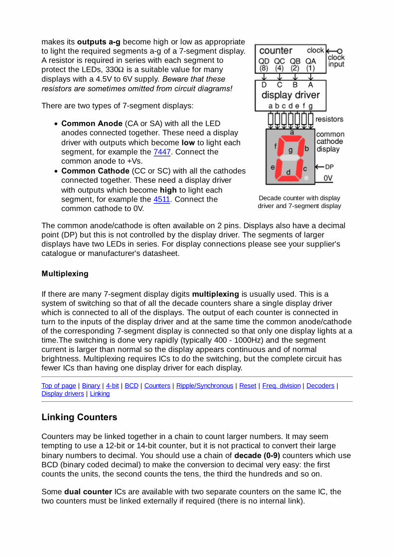
Decade counter with displaydriver and 7-segment display
makes its outputs a-g become high or low as appropriateto light the required segments a-g of a 7-segment display.A resistor is required in series with each segment toprotect the LEDs, 330 is a suitable value for manydisplays with a 4.5V to 6V supply. Beware that theseresistors are sometimes omitted from circuit diagrams!
There are two types of 7-segment displays:
Common Anode (CA or SA) with all the LEDanodes connected together. These need a displaydriver with outputs which become low to light eachsegment, for example the 7447. Connect thecommon anode to +Vs.Common Cathode (CC or SC) with all the cathodesconnected together. These need a display driverwith outputs which become high to light eachsegment, for example the 4511. Connect thecommon cathode to 0V.
The common anode/cathode is often available on 2 pins. Displays also have a decimalpoint (DP) but this is not controlled by the display driver. The segments of largerdisplays have two LEDs in series. For display connections please see your supplier'scatalogue or manufacturer's datasheet.
Multiplexing
If there are many 7-segment display digits multiplexing is usually used. This is asystem of switching so that of all the decade counters share a single display driverwhich is connected to all of the displays. The output of each counter is connected inturn to the inputs of the display driver and at the same time the common anode/cathodeof the corresponding 7-segment display is connected so that only one display lights at atime.The switching is done very rapidly (typically 400 - 1000Hz) and the segmentcurrent is larger than normal so the display appears continuous and of normalbrightness. Multiplexing requires ICs to do the switching, but the complete circuit hasfewer ICs than having one display driver for each display.
Top of page | Binary | 4-bit | BCD | Counters | Ripple/Synchronous | Reset | Freq. division | Decoders |Display drivers | Linking
Linking Counters
Counters may be linked together in a chain to count larger numbers. It may seemtempting to use a 12-bit or 14-bit counter, but it is not practical to convert their largebinary numbers to decimal. You should use a chain of decade (0-9) counters which useBCD (binary coded decimal) to make the conversion to decimal very easy: the firstcounts the units, the second counts the tens, the third the hundreds and so on.
Some dual counter ICs are available with two separate counters on the same IC, thetwo counters must be linked externally if required (there is no internal link).
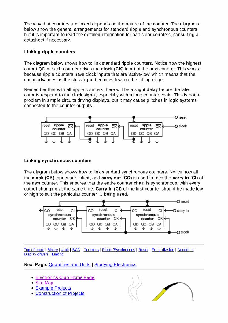
The way that counters are linked depends on the nature of the counter. The diagramsbelow show the general arrangements for standard ripple and synchronous countersbut it is important to read the detailed information for particular counters, consulting adatasheet if necessary.
Linking ripple counters
The diagram below shows how to link standard ripple counters. Notice how the highestoutput QD of each counter drives the clock (CK) input of the next counter. This worksbecause ripple counters have clock inputs that are 'active-low' which means that thecount advances as the clock input becomes low, on the falling-edge.
Remember that with all ripple counters there will be a slight delay before the lateroutputs respond to the clock signal, especially with a long counter chain. This is not aproblem in simple circuits driving displays, but it may cause glitches in logic systemsconnected to the counter outputs.
Linking synchronous counters
The diagram below shows how to link standard synchronous counters. Notice how allthe clock (CK) inputs are linked, and carry out (CO) is used to feed the carry in (CI) ofthe next counter. This ensures that the entire counter chain is synchronous, with everyoutput changing at the same time. Carry in (CI) of the first counter should be made lowor high to suit the particular counter IC being used.
Top of page | Binary | 4-bit | BCD | Counters | Ripple/Synchronous | Reset | Freq. division | Decoders |Display drivers | Linking
Next Page: Quantities and Units | Studying Electronics
Electronics Club Home PageSite MapExample ProjectsConstruction of Projects

Soldering GuideStudy ElectronicsElectronic ComponentsCircuit SymbolsFrequently Asked QuestionsLinks to other Electronics sites
© John Hewes 2011, The Electronics Club, www.kpsec.freeuk.com