Embed Size (px)
Citation preview
C:\Documents and Settings\AMCELROY\Local Settings\Temporary Internet Files\OLK4\RFQ-Fire Apparatus (final).doc 8-27-03
COUNTY OF ALAMEDA
REQUEST FOR QUOTATION NO. 10084/CB/03
SPECIFICATIONS, TERMS & CONDITIONS for
TRIPLE COMBINATION PUMPER FIRE APPARATUS
NETWORKING/BIDDERS CONFERENCES
At
2:00p.m. on
December 3 , 2003 At
Public Works Agency 4825 Gleason Drive Dublin, CA 94568
10:00a.m. on
December 4, 2003 At
Alameda County General Services Agency Conference Room No. 1107
1401 Lakeside Drive Oakland, CA 94612
RESPONSE DUE by
2:00 p.m. on
January 8, 2004 at
Alameda County, GSA-Purchasing 1401 Lakeside Drive, Suite 907
Oakland, CA 94612
C:\Documents and Settings\AMCELROY\Local Settings\Temporary Internet Files\OLK4\RFQ-Fire Apparatus (final).doc Page 2 of 19 8-27-03
COUNTY OF ALAMEDA
REQUEST FOR QUOTATION NO. 10084/CB/03 SPECIFICATIONS, TERMS & CONDITIONS
For FIRE APPARATUS
TABLE OF CONTENTS
Page 1 of 2 Page
I. ACRONYM AND TERM GLOSSARY ...........................................................4-5 II. STATEMENT OF WORK A. Intent............................................................................................................... 5 B. Scope .............................................................................................................. 6 C. Specific Requirements................................................................................6-7 D. Deliverables/Reports ..................................................................................... 7 III. INSTRUCTIONS TO BIDDERS A. County Contacts............................................................................................. 8 B. Calendar of Events......................................................................................8-9 C. Networking/Bidders Conference .................................................................. 9 D. Submittal of Bids ....................................................................................10-11 E. Response Format ......................................................................................... 11 F. Response Content/Submittals.................................................................11-13 G. Notice of Award........................................................................................... 14 H. Bid Protest/Appeals Process...................................................................14-15 IV. TERMS AND CONDITIONS A. Brand Names and Approved Equivalents..............................................15-16 B. Pricing .......................................................................................................... 16 C. Award ........................................................................................................... 16 D. Method of Ordering ..................................................................................... 17 E. Invoicing ...................................................................................................... 17 F. Other Agencies ............................................................................................ 17 G. Liquidated Damages...............................................................................17-18 H. County Provisions...................................................................................18-19 I. General Requirements ................................................................................. 19
Specifications, Terms & Conditions
for Fire Apparatus
C:\Documents and Settings\AMCELROY\Local Settings\Temporary Internet Files\OLK4\RFQ-Fire Apparatus (final).doc Page 3 of 19 8-27-03
TABLE OF CONTENTS Page 2 of 2
ATTACHMENTS Exhibit A - Acknowledgement Exhibit B - Bid Form
Exhibit C – Insurance Requirements Exhibit D1 – Current References
Exhibit D2 – Former References Exhibit E – SLEB Certification Application Package Exhibit F – Small and Local Business Partnering Information Exhibit G – Request for Small and Local or Emerging Preference Exhibit H – Intentionally Omitted Exhibit I – Exceptions, Clarifications, Amendments Exhibit J – Intentionally Omitted Exhibit K – Intentionally Omitted Exhibit L – Intentionally Omitted Exhibit M – RFQ Vendor Bid List Exhibit N - Triple Combination Pumper Specifications
Specifications, Terms & Conditions
for Fire Apparatus
C:\Documents and Settings\AMCELROY\Local Settings\Temporary Internet Files\OLK4\RFQ-Fire Apparatus (final).doc Page 4 of 19 8-27-03
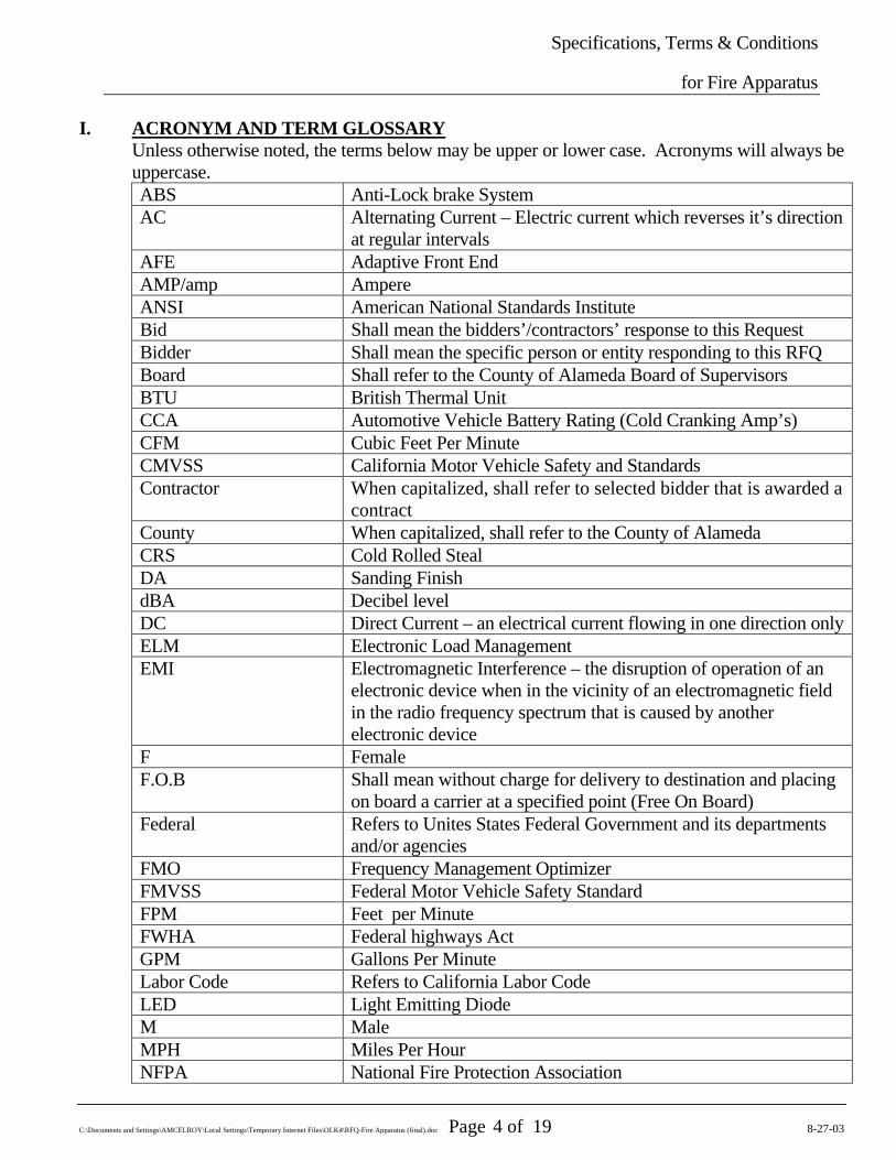
I. ACRONYM AND TERM GLOSSARY Unless otherwise noted, the terms below may be upper or lower case. Acronyms will always be uppercase. ABS Anti-Lock brake System AC Alternating Current – Electric current which reverses it’s direction
at regular intervals AFE Adaptive Front End AMP/amp Ampere ANSI American National Standards Institute Bid Shall mean the bidders’/contractors’ response to this Request Bidder Shall mean the specific person or entity responding to this RFQ Board Shall refer to the County of Alameda Board of Supervisors BTU British Thermal Unit CCA Automotive Vehicle Battery Rating (Cold Cranking Amp’s) CFM Cubic Feet Per Minute CMVSS California Motor Vehicle Safety and Standards Contractor When capitalized, shall refer to selected bidder that is awarded a
contract County When capitalized, shall refer to the County of Alameda CRS Cold Rolled Steal DA Sanding Finish dBA Decibel level DC Direct Current – an electrical current flowing in one direction onlyELM Electronic Load Management EMI Electromagnetic Interference – the disruption of operation of an
electronic device when in the vicinity of an electromagnetic field in the radio frequency spectrum that is caused by another electronic device
F Female F.O.B Shall mean without charge for delivery to destination and placing
on board a carrier at a specified point (Free On Board) Federal Refers to Unites States Federal Government and its departments
and/or agencies FMO Frequency Management Optimizer FMVSS Federal Motor Vehicle Safety Standard FPM Feet per Minute FWHA Federal highways Act GPM Gallons Per Minute Labor Code Refers to California Labor Code LED Light Emitting Diode M Male MPH Miles Per Hour NFPA National Fire Protection Association
Specifications, Terms & Conditions
for Fire Apparatus
C:\Documents and Settings\AMCELROY\Local Settings\Temporary Internet Files\OLK4\RFQ-Fire Apparatus (final).doc Page 5 of 19 8-27-03
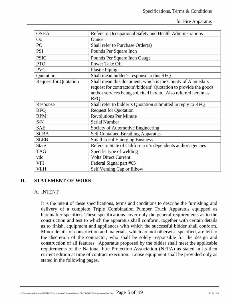
OSHA Refers to Occupational Safety and Health Administrations Oz Ounce PO Shall refer to Purchase Order(s) PSI Pounds Per Square Inch PSIG Pounds Per Square Inch Gauge PTO Power Take Off PVC Plastic Piping Quotation Shall mean bidder’s response to this RFQ Request for Quotation Shall mean this document, which is the County of Alameda’s
request for contractors’/bidders’ Quotation to provide the goods and/or services being solicited herein. Also referred herein as RFQ
Response Shall refer to bidder’s Quotation submitted in reply to RFQ RFQ Request for Quotation RPM Revolutions Per Minute S/N Serial Number SAE Society of Automotive Engineering SCBA Self Contained Breathing Apparatus SLEB Small Local Emerging Business State Refers to State of California it’s dependents and/or agencies TAG Specific type of welding vdc Volts Direct Current VFI Federal Signal part #65 VLH Self Venting Cap or Elbow
II. STATEMENT OF WORK
A. INTENT
It is the intent of these specifications, terms and conditions to describe the furnishing and delivery of a complete Triple Combination Pumper Truck Apparatus equipped as hereinafter specified. These specifications cover only the general requirements as to the construction and test to which the apparatus shall conform, together with certain details as to finish, equipment and appliances with which the successful bidder shall conform. Minor details of construction and materials, which are not otherwise specified, are left to the discretion of the contractor, who shall be solely responsible for the design and construction of all features. Apparatus proposed by the bidder shall meet the applicable requirements of the National Fire Protection Association (NFPA) as stated in its then current edition at time of contract execution. Loose equipment shall be provided only as stated in the following pages.
Specifications, Terms & Conditions
for Fire Apparatus
C:\Documents and Settings\AMCELROY\Local Settings\Temporary Internet Files\OLK4\RFQ-Fire Apparatus (final).doc Page 6 of 19 8-27-03
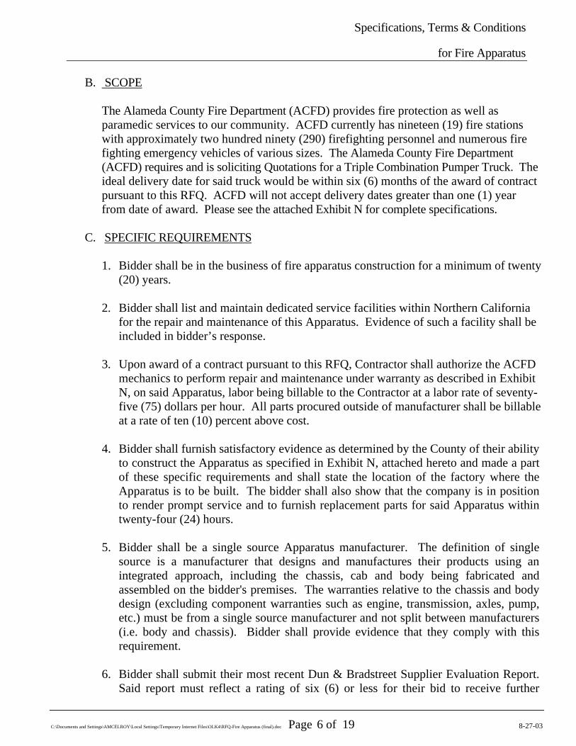
B. SCOPE
The Alameda County Fire Department (ACFD) provides fire protection as well as paramedic services to our community. ACFD currently has nineteen (19) fire stations with approximately two hundred ninety (290) firefighting personnel and numerous fire fighting emergency vehicles of various sizes. The Alameda County Fire Department (ACFD) requires and is soliciting Quotations for a Triple Combination Pumper Truck. The ideal delivery date for said truck would be within six (6) months of the award of contract pursuant to this RFQ. ACFD will not accept delivery dates greater than one (1) year from date of award. Please see the attached Exhibit N for complete specifications.
C. SPECIFIC REQUIREMENTS
1. Bidder shall be in the business of fire apparatus construction for a minimum of twenty
(20) years.
2. Bidder shall list and maintain dedicated service facilities within Northern California for the repair and maintenance of this Apparatus. Evidence of such a facility shall be included in bidder’s response.
3. Upon award of a contract pursuant to this RFQ, Contractor shall authorize the ACFD
mechanics to perform repair and maintenance under warranty as described in Exhibit N, on said Apparatus, labor being billable to the Contractor at a labor rate of seventy-five (75) dollars per hour. All parts procured outside of manufacturer shall be billable at a rate of ten (10) percent above cost.
4. Bidder shall furnish satisfactory evidence as determined by the County of their ability
to construct the Apparatus as specified in Exhibit N, attached hereto and made a part of these specific requirements and shall state the location of the factory where the Apparatus is to be built. The bidder shall also show that the company is in position to render prompt service and to furnish replacement parts for said Apparatus within twenty-four (24) hours.
5. Bidder shall be a single source Apparatus manufacturer. The definition of single
source is a manufacturer that designs and manufactures their products using an integrated approach, including the chassis, cab and body being fabricated and assembled on the bidder's premises. The warranties relative to the chassis and body design (excluding component warranties such as engine, transmission, axles, pump, etc.) must be from a single source manufacturer and not split between manufacturers (i.e. body and chassis). Bidder shall provide evidence that they comply with this requirement.
6. Bidder shall submit their most recent Dun & Bradstreet Supplier Evaluation Report. Said report must reflect a rating of six (6) or less for their bid to receive further

Specifications, Terms & Conditions
for Fire Apparatus
C:\Documents and Settings\AMCELROY\Local Settings\Temporary Internet Files\OLK4\RFQ-Fire Apparatus (final).doc Page 7 of 19 8-27-03
consideration. For information on how to obtain a Supplier Evaluation Report, contact Dun & Bradstreet at 1-866-719-7158 or www.dnb.com
7. Some or all references that are requested herein below will be verified. All verified
references must be satisfactory, to the County. Unsatisfactory references will disqualify that bidder.
8. Bidder shall be ISO 9001 certified. These standards sponsored by the "International Organization for Standardization (ISO)" specify the quality systems that shall be established by the manufacturer for design, manufacture, installation and service. A copy of the certificate of compliance shall be included with the bid.
9. Each piece of the new fire or rescue Apparatus shall be warranted to be free from defects in materials or workmanship under normal use and service. Each bidder shall supply, as a part of their bid package, a copy of the warranty or warranties that they propose to provide, and in no case shall it be less than one (1) year on the entire Apparatus. All other warranties, as outlined in these specifications shall be provided in writing as a part of the bid package.
10. The bidder awarded this contract shall provide two (2) manufacturing inspection trips
for two (2) ACFD representatives. The inspection trips shall be scheduled at times mutually agreed upon between the manufacturer's representative and ACFD. All costs such as travel, lodging and meals shall be the responsibility of Bidder.
11. Upon award of this contract, Bidder shall identify a “drop dead” delivery date for the finished Apparatus, to be agreed upon by the County and the Contractor. For every day thereafter, Contractor shall be subject to “Liquidated Damages” as described herein.
D. DELIVERABLES/REPORTS
1. The manufacturer shall supply at time of delivery, complete operation and maintenance manuals covering the completed Apparatus as delivered.
2. A drawing of the proposed Apparatus shall be provided for approval before
construction begins. The sales representative shall also have a copy of the same drawing. The finalized and approved drawing shall become part of the contract documents. This drawing shall indicate the chassis make and model, location of the lights, siren, horns, compartments, major components, etc.
3. Apparatus, to insure proper break in of all components while still under warranty,
shall be delivered under its own power - rail or truck freight shall not be acceptable. Mileage incurred in the delivery of the Apparatus shall not be included in warranty miles in the event that Contractor has total mileage as a warranty limiter. A qualified delivery engineer representing the Contractor shall deliver the Apparatus and remain
Specifications, Terms & Conditions
for Fire Apparatus
C:\Documents and Settings\AMCELROY\Local Settings\Temporary Internet Files\OLK4\RFQ-Fire Apparatus (final).doc Page 8 of 19 8-27-03
for a sufficient length of time to instruct personnel in the proper operation, care and maintenance of the equipment delivered.
III. INSTRUCTIONS TO BIDDERS
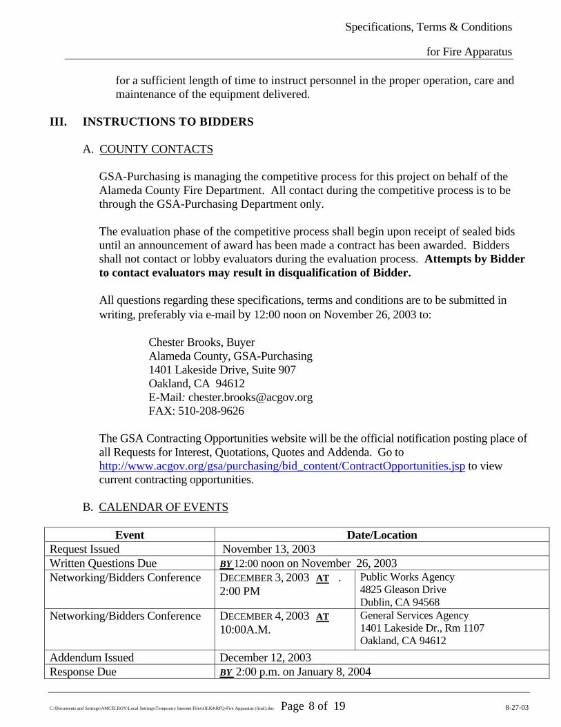
A. COUNTY CONTACTS
GSA-Purchasing is managing the competitive process for this project on behalf of the Alameda County Fire Department. All contact during the competitive process is to be through the GSA-Purchasing Department only.
The evaluation phase of the competitive process shall begin upon receipt of sealed bids until an announcement of award has been made a contract has been awarded. Bidders shall not contact or lobby evaluators during the evaluation process. Attempts by Bidder to contact evaluators may result in disqualification of Bidder. All questions regarding these specifications, terms and conditions are to be submitted in writing, preferably via e-mail by 12:00 noon on November 26, 2003 to:
Chester Brooks, Buyer Alameda County, GSA-Purchasing 1401 Lakeside Drive, Suite 907 Oakland, CA 94612 E-Mail: [email protected] FAX: 510-208-9626
The GSA Contracting Opportunities website will be the official notification posting place of all Requests for Interest, Quotations, Quotes and Addenda. Go to http://www.acgov.org/gsa/purchasing/bid_content/ContractOpportunities.jsp to view current contracting opportunities.
B. CALENDAR OF EVENTS
Event Date/Location Request Issued November 13, 2003 Written Questions Due BY 12:00 noon on November 26, 2003 Networking/Bidders Conference DECEMBER 3, 2003 AT .
2:00 PM Public Works Agency 4825 Gleason Drive Dublin, CA 94568
Networking/Bidders Conference DECEMBER 4, 2003 AT 10:00A.M.
General Services Agency 1401 Lakeside Dr., Rm 1107 Oakland, CA 94612
Addendum Issued December 12, 2003 Response Due BY 2:00 p.m. on January 8, 2004
Specifications, Terms & Conditions
for Fire Apparatus
C:\Documents and Settings\AMCELROY\Local Settings\Temporary Internet Files\OLK4\RFQ-Fire Apparatus (final).doc Page 9 of 19 8-27-03
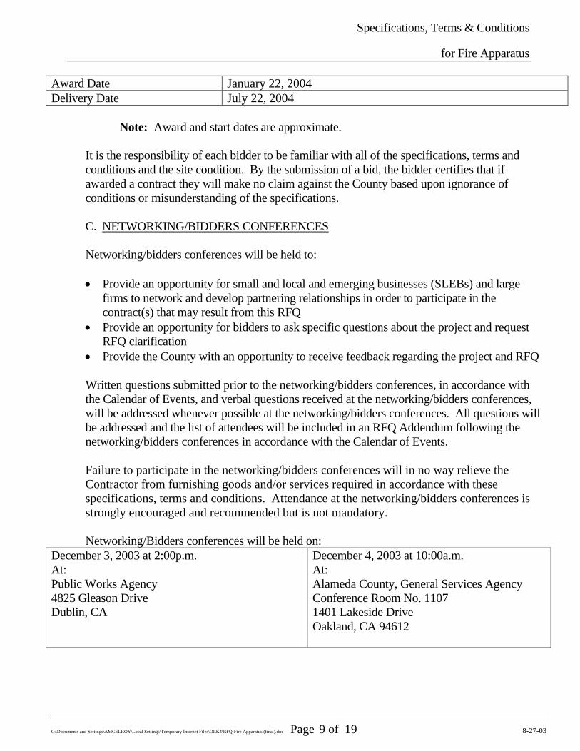
Award Date January 22, 2004 Delivery Date July 22, 2004
Note: Award and start dates are approximate. It is the responsibility of each bidder to be familiar with all of the specifications, terms and conditions and the site condition. By the submission of a bid, the bidder certifies that if awarded a contract they will make no claim against the County based upon ignorance of conditions or misunderstanding of the specifications. C. NETWORKING/BIDDERS CONFERENCES Networking/bidders conferences will be held to: • Provide an opportunity for small and local and emerging businesses (SLEBs) and large
firms to network and develop partnering relationships in order to participate in the contract(s) that may result from this RFQ
• Provide an opportunity for bidders to ask specific questions about the project and request RFQ clarification
• Provide the County with an opportunity to receive feedback regarding the project and RFQ Written questions submitted prior to the networking/bidders conferences, in accordance with the Calendar of Events, and verbal questions received at the networking/bidders conferences, will be addressed whenever possible at the networking/bidders conferences. All questions will be addressed and the list of attendees will be included in an RFQ Addendum following the networking/bidders conferences in accordance with the Calendar of Events. Failure to participate in the networking/bidders conferences will in no way relieve the Contractor from furnishing goods and/or services required in accordance with these specifications, terms and conditions. Attendance at the networking/bidders conferences is strongly encouraged and recommended but is not mandatory.
Networking/Bidders conferences will be held on: December 3, 2003 at 2:00p.m. At: Public Works Agency 4825 Gleason Drive Dublin, CA
December 4, 2003 at 10:00a.m. At: Alameda County, General Services Agency Conference Room No. 1107 1401 Lakeside Drive Oakland, CA 94612
Specifications, Terms & Conditions
for Fire Apparatus
C:\Documents and Settings\AMCELROY\Local Settings\Temporary Internet Files\OLK4\RFQ-Fire Apparatus (final).doc Page 10 of 19 8-27-03
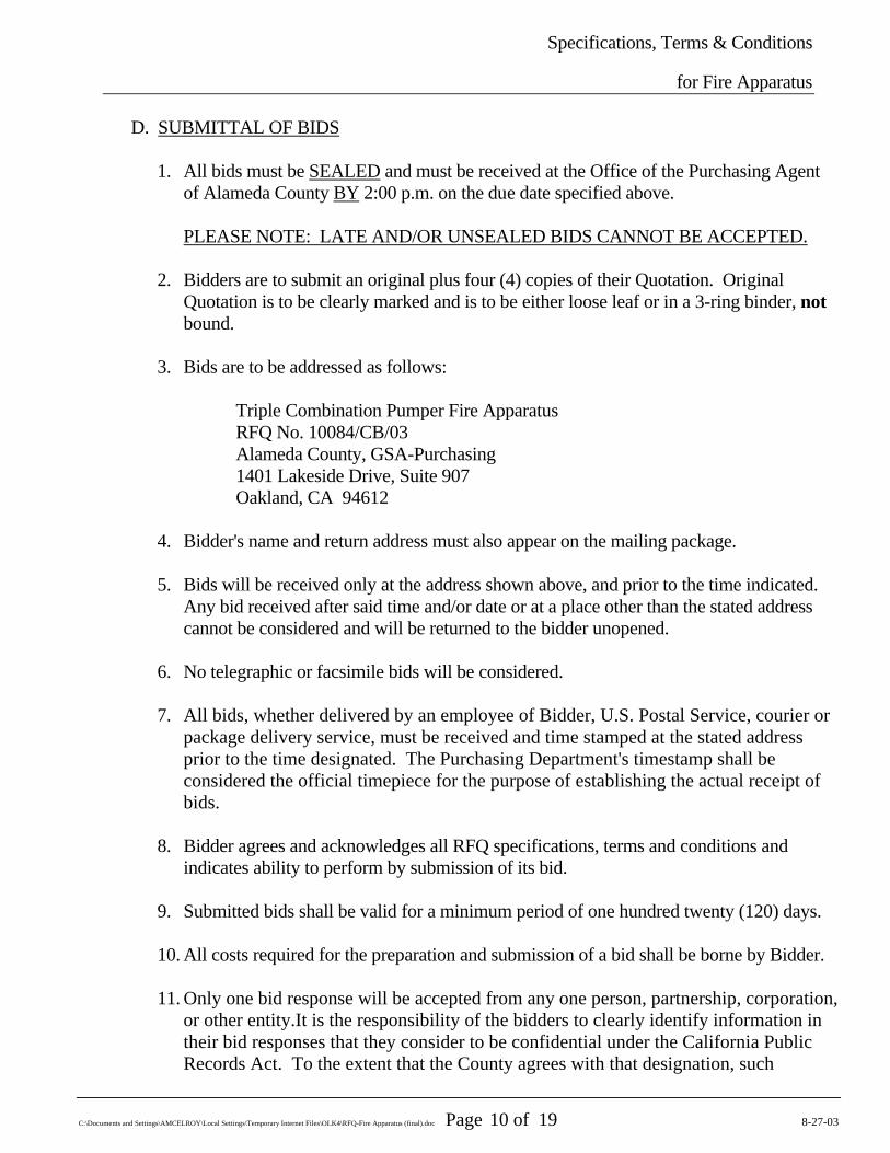
D. SUBMITTAL OF BIDS
1. All bids must be SEALED and must be received at the Office of the Purchasing Agent of Alameda County BY 2:00 p.m. on the due date specified above. PLEASE NOTE: LATE AND/OR UNSEALED BIDS CANNOT BE ACCEPTED.
2. Bidders are to submit an original plus four (4) copies of their Quotation. Original Quotation is to be clearly marked and is to be either loose leaf or in a 3-ring binder, not bound.
3. Bids are to be addressed as follows:
Triple Combination Pumper Fire Apparatus RFQ No. 10084/CB/03 Alameda County, GSA-Purchasing 1401 Lakeside Drive, Suite 907 Oakland, CA 94612
4. Bidder's name and return address must also appear on the mailing package.
5. Bids will be received only at the address shown above, and prior to the time indicated.
Any bid received after said time and/or date or at a place other than the stated address cannot be considered and will be returned to the bidder unopened.
6. No telegraphic or facsimile bids will be considered.
7. All bids, whether delivered by an employee of Bidder, U.S. Postal Service, courier or
package delivery service, must be received and time stamped at the stated address prior to the time designated. The Purchasing Department's timestamp shall be considered the official timepiece for the purpose of establishing the actual receipt of bids.
8. Bidder agrees and acknowledges all RFQ specifications, terms and conditions and
indicates ability to perform by submission of its bid.
9. Submitted bids shall be valid for a minimum period of one hundred twenty (120) days.
10. All costs required for the preparation and submission of a bid shall be borne by Bidder.
11. Only one bid response will be accepted from any one person, partnership, corporation, or other entity.It is the responsibility of the bidders to clearly identify information in
their bid responses that they consider to be confidential under the California Public Records Act. To the extent that the County agrees with that designation, such
Specifications, Terms & Conditions
for Fire Apparatus
C:\Documents and Settings\AMCELROY\Local Settings\Temporary Internet Files\OLK4\RFQ-Fire Apparatus (final).doc Page 11 of 19 8-27-03
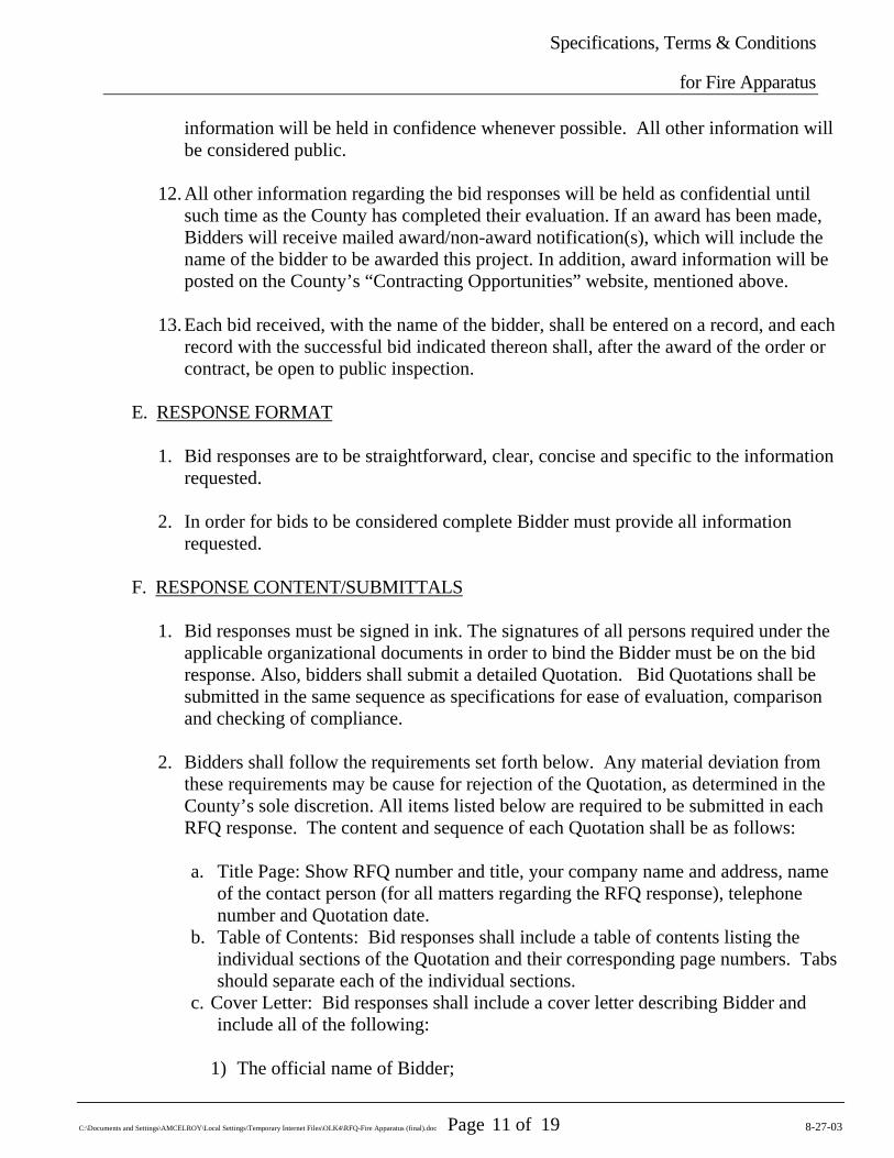
information will be held in confidence whenever possible. All other information will be considered public.
12. All other information regarding the bid responses will be held as confidential until
such time as the County has completed their evaluation. If an award has been made, Bidders will receive mailed award/non-award notification(s), which will include the name of the bidder to be awarded this project. In addition, award information will be posted on the County’s “Contracting Opportunities” website, mentioned above.
13. Each bid received, with the name of the bidder, shall be entered on a record, and each
record with the successful bid indicated thereon shall, after the award of the order or contract, be open to public inspection.
E. RESPONSE FORMAT
1. Bid responses are to be straightforward, clear, concise and specific to the information requested.
2. In order for bids to be considered complete Bidder must provide all information
requested. F. RESPONSE CONTENT/SUBMITTALS
1. Bid responses must be signed in ink. The signatures of all persons required under the
applicable organizational documents in order to bind the Bidder must be on the bid response. Also, bidders shall submit a detailed Quotation. Bid Quotations shall be submitted in the same sequence as specifications for ease of evaluation, comparison and checking of compliance.
2. Bidders shall follow the requirements set forth below. Any material deviation from
these requirements may be cause for rejection of the Quotation, as determined in the County’s sole discretion. All items listed below are required to be submitted in each RFQ response. The content and sequence of each Quotation shall be as follows:
a. Title Page: Show RFQ number and title, your company name and address, name
of the contact person (for all matters regarding the RFQ response), telephone number and Quotation date.
b. Table of Contents: Bid responses shall include a table of contents listing the individual sections of the Quotation and their corresponding page numbers. Tabs should separate each of the individual sections.
c. Cover Letter: Bid responses shall include a cover letter describing Bidder and include all of the following:
1) The official name of Bidder;
Specifications, Terms & Conditions
for Fire Apparatus
C:\Documents and Settings\AMCELROY\Local Settings\Temporary Internet Files\OLK4\RFQ-Fire Apparatus (final).doc Page 12 of 19 8-27-03
2)
3)
4)
5)
6)
7)
8)
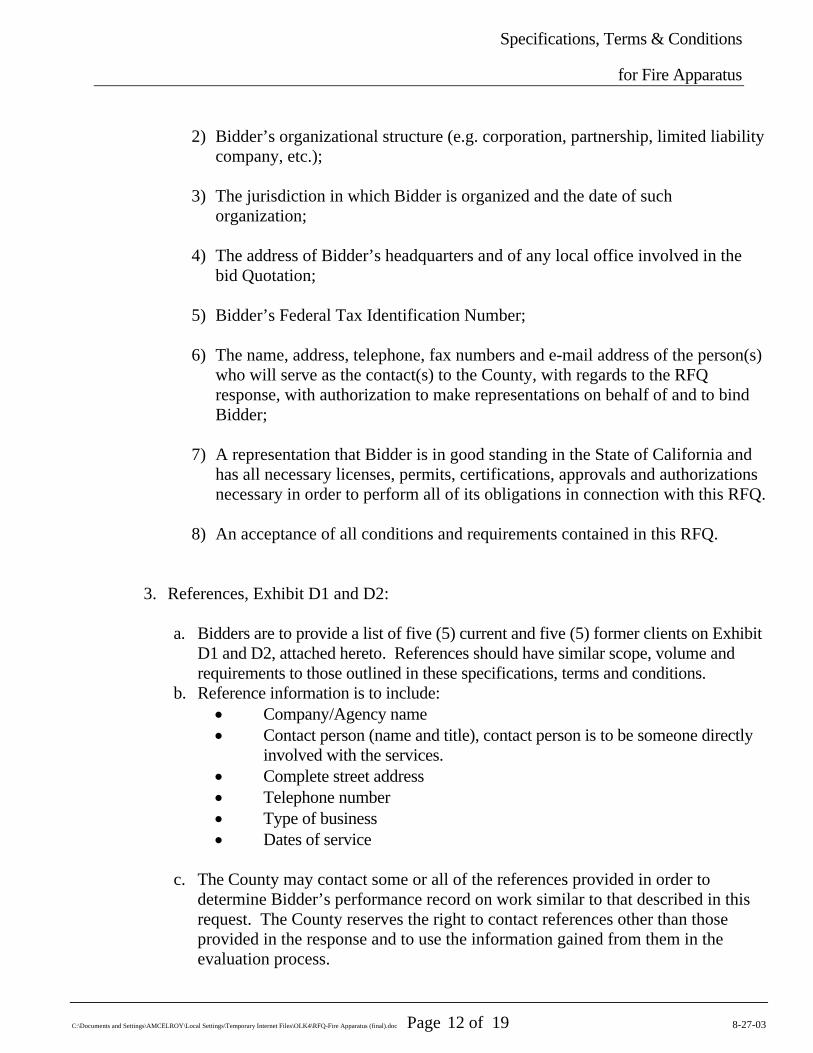
Bidder’s organizational structure (e.g. corporation, partnership, limited liability company, etc.);
The jurisdiction in which Bidder is organized and the date of such organization;
The address of Bidder’s headquarters and of any local office involved in the bid Quotation;
Bidder’s Federal Tax Identification Number;
The name, address, telephone, fax numbers and e-mail address of the person(s) who will serve as the contact(s) to the County, with regards to the RFQ response, with authorization to make representations on behalf of and to bind Bidder;
A representation that Bidder is in good standing in the State of California and has all necessary licenses, permits, certifications, approvals and authorizations necessary in order to perform all of its obligations in connection with this RFQ.
An acceptance of all conditions and requirements contained in this RFQ.
3. References, Exhibit D1 and D2:
a. Bidders are to provide a list of five (5) current and five (5) former clients on Exhibit D1 and D2, attached hereto. References should have similar scope, volume and requirements to those outlined in these specifications, terms and conditions.
b. Reference information is to include: • Company/Agency name • Contact person (name and title), contact person is to be someone directly
involved with the services. • Complete street address • Telephone number • Type of business • Dates of service
c. The County may contact some or all of the references provided in order to
determine Bidder’s performance record on work similar to that described in this request. The County reserves the right to contact references other than those provided in the response and to use the information gained from them in the evaluation process.
Specifications, Terms & Conditions
for Fire Apparatus
C:\Documents and Settings\AMCELROY\Local Settings\Temporary Internet Files\OLK4\RFQ-Fire Apparatus (final).doc Page 13 of 19 8-27-03
d. Bidder shall provide on a separate sheet(s), complete reference information for all
public institutions or agencies for which it provides or has provided comparable product. Each reference shall include location, name, address, telephone and fax numbers of the person who may be contacted for reference information.
4. Bid Form, Exhibit B
Pricing for the procurement of goods and services by the County shall include all taxes, freight and all other costs, or credits, associated with the procurement and delivery to the County of Bidder’s goods and services. Refer to the section entitled “PRICING” under the section designated “TERMS AND CONDITIONS” herein below.
5. Evidence of Insurance
Certificates of insurance are required per the attached Exhibit C from a reputable insurer evidencing all coverages required for the term of the contract of any contract that may be awarded pursuant to this RFQ.
6. Other required Submittals/Exhibits not included above that are required in the bid
response: • Exhibit A, Acknowledgement, signed • Exhibit E, SLEB Certification Application Package, completed, signed, required
documentation attached (if applicable) • Exhibit F, Local, Small and Emerging Business Partnering Information, completed
and signed • Exhibit G, Request for Preference for Local, Small and/or Emerging Vendors,
completed and signed (if applicable). If Applicable, submit the following: i. Copy of a verifiable business license, issued by the County of Alameda
or a City within the County ii. Proof of six (6) month business residency, identifying the name of the
vendor and the local address: any previous contracts with the County, utility bills, and deed of trust or lease agreement.
• Exhibit I, Exceptions, Clarifications and Amendments Form, completed and signed. (The County is under no obligation to accept any exceptions and such exceptions may be a basis for bid disqualification.)
Specifications, Terms & Conditions
for Fire Apparatus
C:\Documents and Settings\AMCELROY\Local Settings\Temporary Internet Files\OLK4\RFQ-Fire Apparatus (final).doc Page 14 of 19 8-27-03
G. NOTICE OF AWARD
1. At the conclusion of the RFQ response evaluation process (“Evaluation Process”), all bidders will be notified in writing of the contract award recommendation, if any, of GSA - Purchasing. The document providing this notification is the Notice of Award.
a. The Notice of Award will provide the following information:
• The name of the bidder being recommended for contract award; • The names of all other bidders; • In summary form Bid numbers, evaluation points for each bidder
2. Debriefings for unsuccessful bidders will be scheduled and provided upon written request and will be restricted to discussion of the unsuccessful offeror’s bid with the Buyer
a. Under no circumstances will any discussion be conducted in regards to contract
negotiations with the successful bidder, etc. b. Debriefing may include review of successful bidder’s Quotation c. Under no circumstance will the protesting party be entitled to poll any member of
the CSC. H. BID PROTEST / APPEALS PROCESS
GSA-Purchasing prides itself on the establishment of fair and competitive contracting procedures and the commitment made to following those procedures. The following is provided in the event that bidders wish to protest the bid process or appeal the recommendation to award a contract for this project.
1. Any bid protest must be submitted in writing to the Deputy Director of GSA -
Purchasing, 1401 Lakeside Drive, Suite 907, Oakland, CA 94612. The bid protest must be submitted before 5:00 p.m. of the fifth (5th) business day following the date of the Notice of Award.
a. The bid protest must contain a complete statement of the basis for the protest. b. The protest must include the name, address and telephone number of the person
representing the protesting party. c. The party filing the protest must concurrently transmit a copy of the protest and
any attached documentation to all other parties with a direct financial interest which may be adversely affected by the outcome of the protest.
d. The procedure and time limits are mandatory and are the Bidder’s sole and exclusive remedy in the event of Bid Protest.
Specifications, Terms & Conditions
for Fire Apparatus
C:\Documents and Settings\AMCELROY\Local Settings\Temporary Internet Files\OLK4\RFQ-Fire Apparatus (final).doc Page 15 of 19 8-27-03
2. The Bidder’s failure to comply with these procedures shall constitute a waiver of any right to further pursue the Bid Protest, including filing a Government Code claim or legal proceedings.
3. Upon receipt of written protest/appeal, GSA-Purchasing, Deputy Director will review
and provide an opportunity to settle the protest/appeal by mutual agreement, will schedule a meeting to discuss or issue a written response to advise an appeal/protest decision within five (5) working days of review date.
a. Responses will be issued and/or discussed at least five (5) days prior to Board
hearing date. b. Responses will inform the bidder whether or not the recommendation to the Board
is going to change.
4. The decision of the Deputy Director, GSA-Purchasing may be appealed to the Director, GSA. All appeals to the Director, GSA shall be in writing and submitted within five (5) calendar days of notification of decision by the Deputy Director, GSA-Purchasing.
5. The decision of the Director, GSA is the final step of appeal process.
6. The Director, GSA and Deputy Director, GSA-Purchasing will determine if the Board
letter should include (or be amended to include) a brief mention of the grounds of the protest/appeal and provide the recommended resolution, if the issue should be discussed with the Board of Supervisors, and/or if the Board item should be pulled. In addition the following will be considered: a. The recommended protest/appeal solution will support the original
recommendation for award. b. If a protest/appeal has merit, the Board item will be pulled and steps taken to fix
the problem. c. County Counsel will be consulted at a minimum for any matters that are on the
agenda for Closed Session. IV. TERMS AND CONDITIONS A. BRAND NAMES AND APPROVED EQUIVALENTS
1. Any references to manufacturers, trade names, brand names and/or catalog numbers are
intended to be descriptive, but not restrictive, unless otherwise stated, and are intended to indicate the quality level desired. Bidders may offer any equivalent product that meets or exceeds the specifications. Bids based on equivalent products must:
Specifications, Terms & Conditions
for Fire Apparatus
C:\Documents and Settings\AMCELROY\Local Settings\Temporary Internet Files\OLK4\RFQ-Fire Apparatus (final).doc Page 16 of 19 8-27-03
a. Clearly describe the alternate offered and indicate how it differs from the product specified.
b. Include complete descriptive literature and/or specifications as proof that the
proposed alternate will be equal to or better than the specifications.
2. The County reserves the right to be the sole judge of what is equal and acceptable and may require Bidder to provide additional information and/or samples.
3. If Bidder does not specify otherwise, it is understood that the referenced brand will be
supplied. B. PRICING
1. All prices are to be F.O.B. destination. Any freight/delivery charges are to be included
in the price of the Apparatus. 2. The County is soliciting a lump sum price for this project. The price quoted shall be the
total cost the County will pay for this project including taxes and all other charges. 3. All prices quoted shall be in United States dollars and "whole cent," no cent fractions
shall be used. There are no exceptions. 4. The County has the right to decline to award this contract if it is determined that
proposed pricing is not competitively priced with similar sized counties or non-county agencies within the State of California.
5. Price quotes shall include any and all payment incentives available to the County.
C. AWARD
6. Quotations will be evaluated by a committee and will be ranked in accordance with the
RFQ section entitled “Evaluation Criteria/Selection Committee.” 7. The committee will recommend award to the bidder who, in its opinion, has submitted
the Quotation that best serves the overall interests of the County and attains the highest overall point score. Award may not necessarily be made to the bidder with the lowest price.
8. The County reserves the right to reject any or all responses that materially differ from
any terms contained herein or from any Exhibits attached hereto and to waive informalities and minor irregularities in responses received.
9. The County reserves the right to award to a single or multiple contractors.
Specifications, Terms & Conditions
for Fire Apparatus
C:\Documents and Settings\AMCELROY\Local Settings\Temporary Internet Files\OLK4\RFQ-Fire Apparatus (final).doc Page 17 of 19 8-27-03
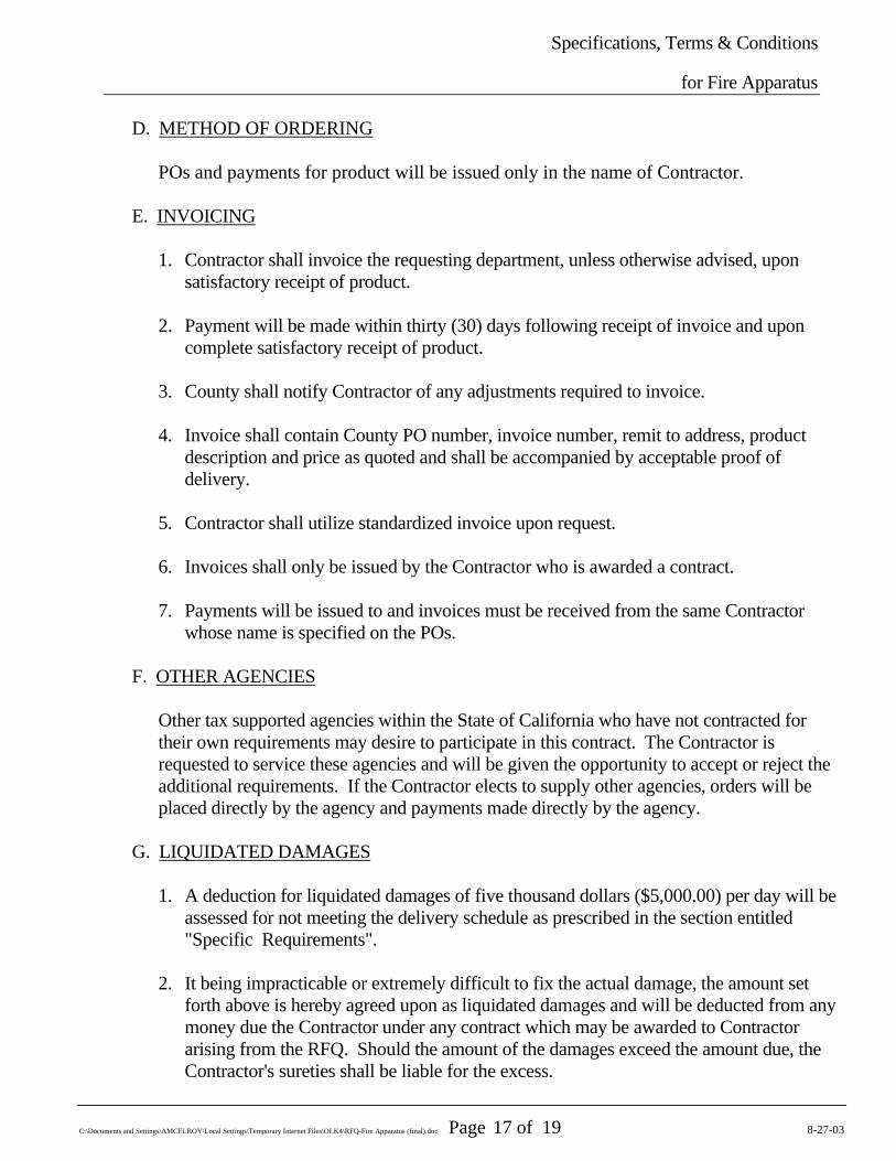
D. METHOD OF ORDERING
POs and payments for product will be issued only in the name of Contractor. E. INVOICING
1. Contractor shall invoice the requesting department, unless otherwise advised, upon satisfactory receipt of product.
2. Payment will be made within thirty (30) days following receipt of invoice and upon complete satisfactory receipt of product.
3. County shall notify Contractor of any adjustments required to invoice.
4. Invoice shall contain County PO number, invoice number, remit to address, product
description and price as quoted and shall be accompanied by acceptable proof of delivery.
5. Contractor shall utilize standardized invoice upon request.
6. Invoices shall only be issued by the Contractor who is awarded a contract.
7. Payments will be issued to and invoices must be received from the same Contractor
whose name is specified on the POs. F. OTHER AGENCIES
Other tax supported agencies within the State of California who have not contracted for their own requirements may desire to participate in this contract. The Contractor is requested to service these agencies and will be given the opportunity to accept or reject the additional requirements. If the Contractor elects to supply other agencies, orders will be placed directly by the agency and payments made directly by the agency.
G. LIQUIDATED DAMAGES
1. A deduction for liquidated damages of five thousand dollars ($5,000.00) per day will be assessed for not meeting the delivery schedule as prescribed in the section entitled "Specific Requirements".
2. It being impracticable or extremely difficult to fix the actual damage, the amount set
forth above is hereby agreed upon as liquidated damages and will be deducted from any money due the Contractor under any contract which may be awarded to Contractor arising from the RFQ. Should the amount of the damages exceed the amount due, the Contractor's sureties shall be liable for the excess.
Specifications, Terms & Conditions
for Fire Apparatus
C:\Documents and Settings\AMCELROY\Local Settings\Temporary Internet Files\OLK4\RFQ-Fire Apparatus (final).doc Page 18 of 19 8-27-03
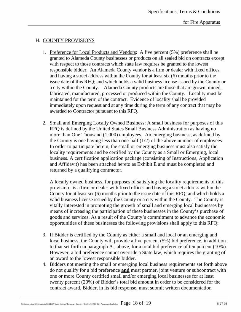
H. COUNTY PROVISIONS
1. Preference for Local Products and Vendors: A five percent (5%) preference shall be
granted to Alameda County businesses or products on all sealed bid on contracts except with respect to those contracts which state law requires be granted to the lowest responsible bidder. An Alameda County vendor is a firm or dealer with fixed offices and having a street address within the County for at least six (6) months prior to the issue date of this RFQ; and which holds a valid business license issued by the County or a city within the County. Alameda County products are those that are grown, mined, fabricated, manufactured, processed or produced within the County. Locality must be maintained for the term of the contract. Evidence of locality shall be provided immediately upon request and at any time during the term of any contract that may be awarded to Contractor pursuant to this RFQ.
2. Small and Emerging Locally Owned Business: A small business for purposes of this
RFQ is defined by the United States Small Business Administration as having no more than One Thousand (1,000) employees. An emerging business, as defined by the County is one having less than one-half (1/2) of the above number of employees. In order to participate herein, the small or emerging business must also satisfy the locality requirements and be certified by the County as a Small or Emerging, local business. A certification application package (consisting of Instructions, Application and Affidavit) has been attached hereto as Exhibit E and must be completed and returned by a qualifying contractor.
A locally owned business, for purposes of satisfying the locality requirements of this provision, is a firm or dealer with fixed offices and having a street address within the County for at least six (6) months prior to the issue date of this RFQ; and which holds a valid business license issued by the County or a city within the County. The County is vitally interested in promoting the growth of small and emerging local businesses by means of increasing the participation of these businesses in the County’s purchase of goods and services. As a result of the County’s commitment to advance the economic opportunities of these businesses the following provisions shall apply to this RFQ:
3. If Bidder is certified by the County as either a small and local or an emerging and
local business, the County will provide a five percent (5%) bid preference, in addition to that set forth in paragraph A., above, for a total bid preference of ten percent (10%). However, a bid preference cannot override a State law, which requires the granting of an award to the lowest responsible bidder.
4. Bidders not meeting the small or emerging local business requirements set forth above do not qualify for a bid preference and must partner, joint venture or subcontract with one or more County certified small and/or emerging local businesses for at least twenty percent (20%) of Bidder’s total bid amount in order to be considered for the contract award. Bidder, in its bid response, must submit written documentation

Specifications, Terms & Conditions
for Fire Apparatus
C:\Documents and Settings\AMCELROY\Local Settings\Temporary Internet Files\OLK4\RFQ-Fire Apparatus (final).doc Page 19 of 19 8-27-03
evidencing a firm contractual commitment to meeting this minimum local participation requirement. Participation of a small and/or emerging local business must be maintained for the term of any contract resulting from this RFQ. Evidence of participation shall be provided immediately upon request at any time during the term of such contract. Contractor shall provide quarterly participation reports during the term of said contract and a final account statement at the end of the contract to the County Business Outreach Officer.
The County reserves the right to waive these small/emerging local business participation requirements in this RFQ, if the additional estimated cost to the County, which may result from inclusion of these requirements, exceeds five percent (5%) of the total estimated contract amount or Ten Thousand Dollars ($10,000), whichever is less.
If additional information is needed regarding this requirement, please contact Linda Moore, Business Outreach Officer, Alameda County General Services Agency, at (510) 208-9717 or via E-mail at [email protected].
I. GENERAL REQUIREMENTS
Bidder shall possess all permits, licenses and professional credentials necessary to supply product as specified under this RFQ.
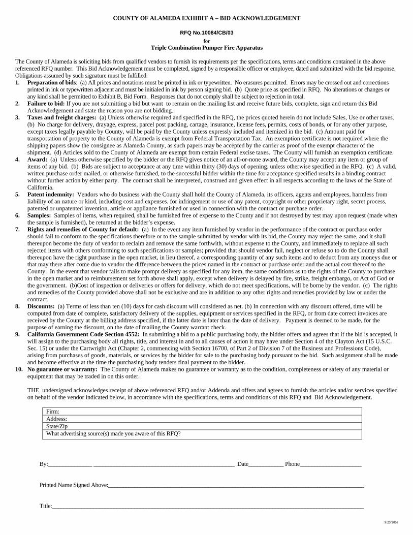
COUNTY OF ALAMEDA EXHIBIT A – BID ACKNOWLEDGEMENT
9/23/2002
RFQ No.10084/CB/03 for
Triple Combination Pumper Fire Apparatus
The County of Alameda is soliciting bids from qualified vendors to furnish its requirements per the specifications, terms and conditions contained in the above referenced RFQ number. This Bid Acknowledgement must be completed, signed by a responsible officer or employee, dated and submitted with the bid response. Obligations assumed by such signature must be fulfilled. 1. Preparation of bids: (a) All prices and notations must be printed in ink or typewritten. No erasures permitted. Errors may be crossed out and corrections
printed in ink or typewritten adjacent and must be initialed in ink by person signing bid. (b) Quote price as specified in RFQ. No alterations or changes or any kind shall be permitted to Exhibit B, Bid Form. Responses that do not comply shall be subject to rejection in total.
2. Failure to bid: If you are not submitting a bid but want to remain on the mailing list and receive future bids, complete, sign and return this Bid Acknowledgement and state the reason you are not bidding.
3. Taxes and freight charges: (a) Unless otherwise required and specified in the RFQ, the prices quoted herein do not include Sales, Use or other taxes. (b) No charge for delivery, drayage, express, parcel post packing, cartage, insurance, license fees, permits, costs of bonds, or for any other purpose, except taxes legally payable by County, will be paid by the County unless expressly included and itemized in the bid. (c) Amount paid for transportation of property to the County of Alameda is exempt from Federal Transportation Tax. An exemption certificate is not required where the shipping papers show the consignee as Alameda County, as such papers may be accepted by the carrier as proof of the exempt character of the shipment. (d) Articles sold to the County of Alameda are exempt from certain Federal excise taxes. The County will furnish an exemption certificate.
4. Award: (a) Unless otherwise specified by the bidder or the RFQ gives notice of an all-or-none award, the County may accept any item or group of items of any bid. (b) Bids are subject to acceptance at any time within thirty (30) days of opening, unless otherwise specified in the RFQ. (c) A valid, written purchase order mailed, or otherwise furnished, to the successful bidder within the time for acceptance specified results in a binding contract without further action by either party. The contract shall be interpreted, construed and given effect in all respects according to the laws of the State of California.
5. Patent indemnity: Vendors who do business with the County shall hold the County of Alameda, its officers, agents and employees, harmless from liability of an nature or kind, including cost and expenses, for infringement or use of any patent, copyright or other proprietary right, secret process, patented or unpatented invention, article or appliance furnished or used in connection with the contract or purchase order.
6. Samples: Samples of items, when required, shall be furnished free of expense to the County and if not destroyed by test may upon request (made when the sample is furnished), be returned at the bidder’s expense.
7. Rights and remedies of County for default: (a) In the event any item furnished by vendor in the performance of the contract or purchase order should fail to conform to the specifications therefore or to the sample submitted by vendor with its bid, the County may reject the same, and it shall thereupon become the duty of vendor to reclaim and remove the same forthwith, without expense to the County, and immediately to replace all such rejected items with others conforming to such specifications or samples; provided that should vendor fail, neglect or refuse so to do the County shall thereupon have the right purchase in the open market, in lieu thereof, a corresponding quantity of any such items and to deduct from any moneys due or that may there after come due to vendor the difference between the prices named in the contract or purchase order and the actual cost thereof to the County. In the event that vendor fails to make prompt delivery as specified for any item, the same conditions as to the rights of the County to purchase in the open market and to reimbursement set forth above shall apply, except when delivery is delayed by fire, strike, freight embargo, or Act of God or the government. (b)Cost of inspection or deliveries or offers for delivery, which do not meet specifications, will be borne by the vendor. (c) The rights and remedies of the County provided above shall not be exclusive and are in addition to any other rights and remedies provided by law or under the contract.
8. Discounts: (a) Terms of less than ten (10) days for cash discount will considered as net. (b) In connection with any discount offered, time will be computed from date of complete, satisfactory delivery of the supplies, equipment or services specified in the RFQ, or from date correct invoices are received by the County at the billing address specified, if the latter date is later than the date of delivery. Payment is deemed to be made, for the purpose of earning the discount, on the date of mailing the County warrant check.
9. California Government Code Section 4552: In submitting a bid to a public purchasing body, the bidder offers and agrees that if the bid is accepted, it will assign to the purchasing body all rights, title, and interest in and to all causes of action it may have under Section 4 of the Clayton Act (15 U.S.C. Sec. 15) or under the Cartwright Act (Chapter 2, commencing with Section 16700, of Part 2 of Division 7 of the Business and Professions Code), arising from purchases of goods, materials, or services by the bidder for sale to the purchasing body pursuant to the bid. Such assignment shall be made and become effective at the time the purchasing body tenders final payment to the bidder.
10. No guarantee or warranty: The County of Alameda makes no guarantee or warranty as to the condition, completeness or safety of any material or equipment that may be traded in on this order.
THE undersigned acknowledges receipt of above referenced RFQ and/or Addenda and offers and agrees to furnish the articles and/or services specified on behalf of the vendor indicated below, in accordance with the specifications, terms and conditions of this RFQ and Bid Acknowledgement.
Firm: Address: State/Zip What advertising source(s) made you aware of this RFQ?
By:_______________ ________________________________________________ Date____________ Phone_____________________ Printed Name Signed Above:_______________________________________________________________________________________ Title:__________________________________________________________________________________________________________
9/23/2002
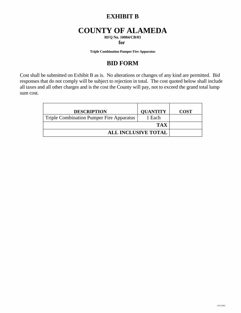
EXHIBIT B
COUNTY OF ALAMEDA RFQ No. 10084/CB/03
for
Triple Combination Pumper Fire Apparatus
BID FORM
Cost shall be submitted on Exhibit B as is. No alterations or changes of any kind are permitted. Bid responses that do not comply will be subject to rejection in total. The cost quoted below shall include all taxes and all other charges and is the cost the County will pay, not to exceed the grand total lump sum cost.
DESCRIPTION QUANTITY COST Triple Combination Pumper Fire Apparatus 1 Each
TAX ALL INCLUSIVE TOTAL
9/23/2002
EXHIBIT C
COUNTY OF ALAMEDA MINIMUM INSURANCE REQUIREMENTS
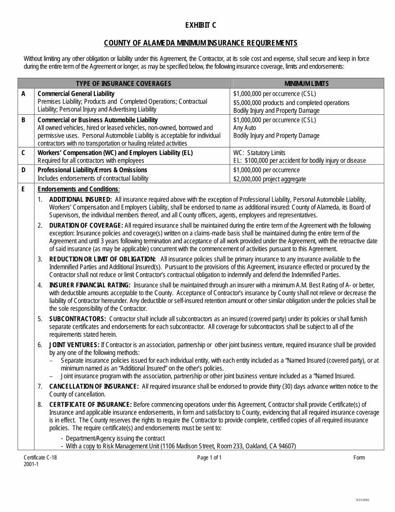
Without limiting any other obligation or liability under this Agreement, the Contractor, at its sole cost and expense, shall secure and keep in force during the entire term of the Agreement or longer, as may be specified below, the following insurance coverage, limits and endorsements:
TYPE OF INSURANCE COVERAGES MINIMUM LIMITS A Commercial General Liability
Premises Liability; Products and Completed Operations; Contractual Liability; Personal Injury and Advertising Liability
$1,000,000 per occurrence (CSL) $5,000,000 products and completed operations Bodily Injury and Property Damage
B Commercial or Business Automobile Liability All owned vehicles, hired or leased vehicles, non-owned, borrowed and permissive uses. Personal Automobile Liability is acceptable for individual contractors with no transportation or hauling related activities
$1,000,000 per occurrence (CSL) Any Auto Bodily Injury and Property Damage
C Workers’ Compensation (WC) and Employers Liability (EL) Required for all contractors with employees
WC: Statutory Limits EL: $100,000 per accident for bodily injury or disease
D Professional Liability/Errors & Omissions Includes endorsements of contractual liability
$1,000,000 per occurrence $2,000,000 project aggregate
E
Endorsements and Conditions: 1. ADDITIONAL INSURED: All insurance required above with the exception of Professional Liability, Personal Automobile Liability,
Workers’ Compensation and Employers Liability, shall be endorsed to name as additional insured: County of Alameda, its Board of Supervisors, the individual members thereof, and all County officers, agents, employees and representatives.
2. DURATION OF COVERAGE: All required insurance shall be maintained during the entire term of the Agreement with the following exception: Insurance policies and coverage(s) written on a claims-made basis shall be maintained during the entire term of the Agreement and until 3 years following termination and acceptance of all work provided under the Agreement, with the retroactive date of said insurance (as may be applicable) concurrent with the commencement of activities pursuant to this Agreement.
3. REDUCTION OR LIMIT OF OBLIGATION: All insurance policies shall be primary insurance to any insurance available to the Indemnified Parties and Additional Insured(s). Pursuant to the provisions of this Agreement, insurance effected or procured by the Contractor shall not reduce or limit Contractor’s contractual obligation to indemnify and defend the Indemnified Parties.
4. INSURER FINANCIAL RATING: Insurance shall be maintained through an insurer with a minimum A.M. Best Rating of A- or better, with deductible amounts acceptable to the County. Acceptance of Contractor’s insurance by County shall not relieve or decrease the liability of Contractor hereunder. Any deductible or self-insured retention amount or other similar obligation under the policies shall be the sole responsibility of the Contractor.
5. SUBCONTRACTORS: Contractor shall include all subcontractors as an insured (covered party) under its policies or shall furnish separate certificates and endorsements for each subcontractor. All coverage for subcontractors shall be subject to all of the requirements stated herein.
6. JOINT VENTURES: If Contractor is an association, partnership or other joint business venture, required insurance shall be provided by any one of the following methods: – Separate insurance policies issued for each individual entity, with each entity included as a “Named Insured (covered party), or at
minimum named as an “Additional Insured” on the other’s policies. – Joint insurance program with the association, partnership or other joint business venture included as a “Named Insured.
7. CANCELLATION OF INSURANCE: All required insurance shall be endorsed to provide thirty (30) days advance written notice to the County of cancellation.
8. CERTIFICATE OF INSURANCE: Before commencing operations under this Agreement, Contractor shall provide Certificate(s) of Insurance and applicable insurance endorsements, in form and satisfactory to County, evidencing that all required insurance coverage is in effect. The County reserves the rights to require the Contractor to provide complete, certified copies of all required insurance policies. The require certificate(s) and endorsements must be sent to:
- Department/Agency issuing the contract - With a copy to Risk Management Unit (1106 Madison Street, Room 233, Oakland, CA 94607)
Certificate C-18 Page 1 of 1 Form 2001-1
9/23/2002
EXHIBIT D-1 COUNTY OF ALAMEDA
RFQ No. 10084/CB/032 for
Triple Combination Pumper Fire Apparatus
CURRENT REFERENCES Company Name: Address: City, State, Zip Code: Contact Person: Telephone Number: Type of Business: Dates of Service:
Company Name: Address: City, State, Zip Code: Contact Person: Telephone Number: Type of Business: Dates of Service:
Company Name: Address: City, State, Zip Code: Contact Person: Telephone Number: Type of Business: Dates of Service:
Company Name: Address: City, State, Zip Code: Contact Person: Telephone Number: Type of Business: Dates of Service:
Company Name: Address: City, State, Zip Code: Contact Person: Telephone Number: Type of Business: Dates of Service:
Company Name:
9/23/2002
EXHIBIT D-2 COUNTY OF ALAMEDA
RFQ No. 10084/CB/03 for
Triple Combination Pumper Fire Apparatus
FORMER REFERENCES Company Name: Address: City, State, Zip Code: Contact Person: Telephone Number: Type of Business: Dates of Service:
Company Name: Address: City, State, Zip Code: Contact Person: Telephone Number: Type of Business: Dates of Service:
Company Name: Address: City, State, Zip Code: Contact Person: Telephone Number: Type of Business: Dates of Service:
Company Name: Address: City, State, Zip Code: Contact Person: Telephone Number: Type of Business: Dates of Service:
Company Name: Address: City, State, Zip Code: Contact Person: Telephone Number: Type of Business: Dates of Service:
Company Name:
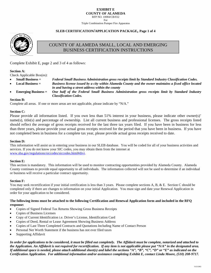
EXHIBIT E COUNTY OF ALAMEDA
RFP NO. 10084/CB/032 For
Triple Combination Pumper Fire Apparatus
SLEB CERTIFICATION/APPLICATION PACKAGE, Page 1 of 4
Complete Exhibit E, pag Section A: Check Applicable Box(es):• Small Business = • Local Business =
• Emerging Business =
Section B: Complete all areas. If one Section C: Please provide all informname(s), title(s) and pershould reflect the averagthan three years, please pnot completed been in bu Section D: This information will assisservices. If you do not knowww.sba.gov/regulations/s
Section E: This section is mandatory. County continues to providor business will receive a p
Section F: You may seek recertificatiocompleted only if there areorder for your application t The following items mustresponse: • Copies of Signed Fede• Copies of Business Lic• Copy of Current Ident• Copies of Deed, Renta• Copies of Last Three C• Personal Net Worth St• Supporting Affidavit In order for applications tthe Application. An AffidaIf additional space is needCertification Application.
COUNTY OF ALAMEDA SMALL, LOCAL AND EMERGINGBUSINESS CERTIFICATION INSTRUCTIONS
9/23/2002
e 2 and 3 of 4 as follows:
Federal Small Business Administration gross receipts limit by Standard Industry Classification Codes.
Business license issued by a city within Alameda County and the owner maintains a fixed office located in and having a street address within the county
One half of the Federal Small Business Administration gross receipts limit by Standard Industry Classification Codes.
or more areas are not applicable, please indicate by “N/A.”
ation listed. If you own less than 51% interest in your business, please indicate other owner(s)’ centage of ownership. List all current business and professional licenses. The gross receipts listed e of gross receipts received for the last three tax years filed. If you have been in business for less rovide your actual gross receipts received for the period that you have been in business. If you have siness for a complete tax year, please provide actual gross receipts received to date.
t us in entering your business in our SLEB database. You will be coded for all of your business activities and w your SIC codes, you may obtain them from the internet at iccodes/siccodes.html#divi.
This information will be used to monitor contracting opportunities provided by Alameda County. Alameda e equal opportunity to all individuals. The information collected will not be used to determine if an individual articular contract opportunity.
n if your initial certification is less than 3 years. Please complete sections A, B, & E. Section C should be changes to information on your initial Application. You must sign and date your Renewal Application in o be considered.
be attached to the following Certification and Renewal Application form and included in the RFQ
ral Tax Returns Showing Gross Business Receipts enses
ification i.e. Driver’s License, Identification Card l or Lease Agreement Showing Business Address ompleted Contracts and Quotations Including Name of Contact Person
atement if the business has not ever filed taxes
o be considered, it must be filled out completely. The Affidavit must be complete, notarized and attached to vit is not required for recertification. If any item is not applicable please put “N/A” in the designated area. ed, please attach additional sheet(s) and label the sections “A”, “B”, “C”, “D” or “E” as indicated on the For additional information and/or assistance completing Exhibit E, contact Linda Moore, (510) 208-9717.
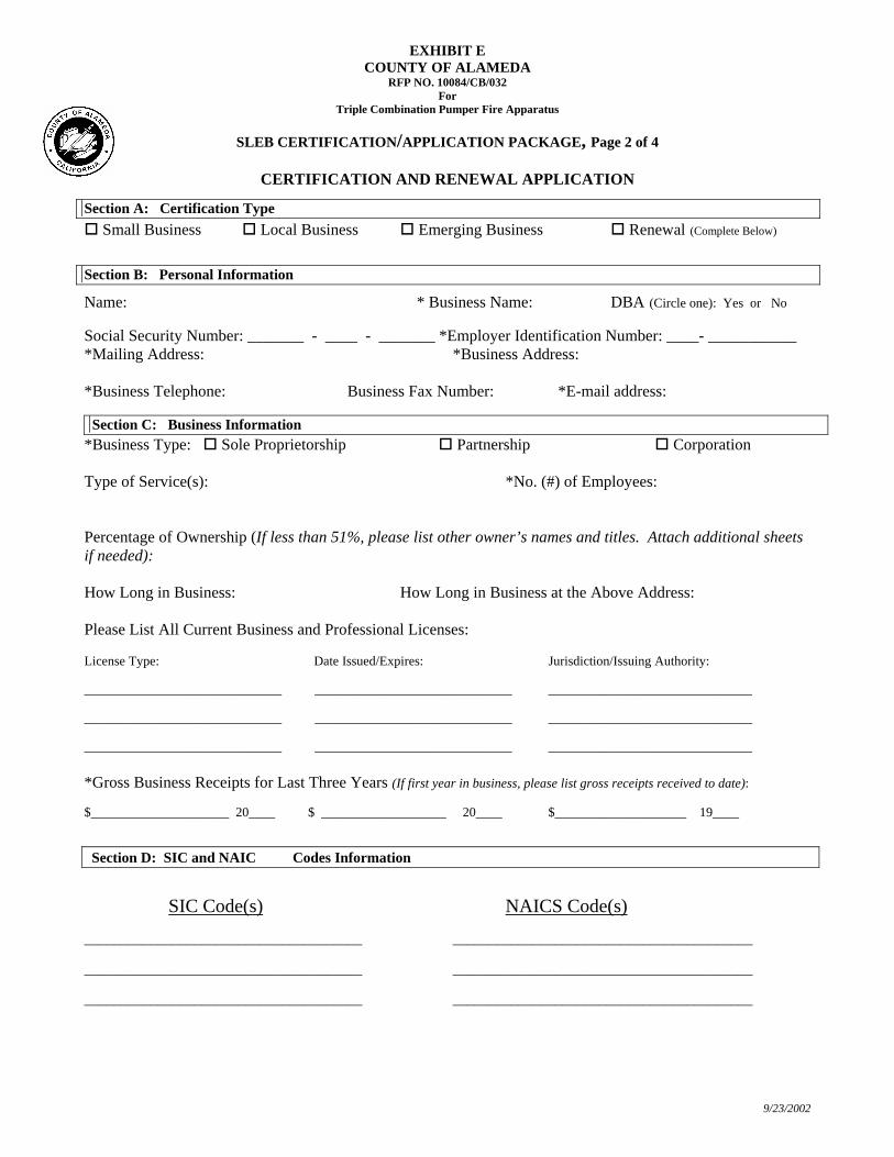
EXHIBIT E COUNTY OF ALAMEDA
RFP NO. 10084/CB/032 For
Triple Combination Pumper Fire Apparatus
SLEB CERTIFICATION/APPLICATION PACKAGE, Page 2 of 4
9/23/2002
CERTIFICATION AND RENEWAL APPLICATION
Section A: Certification Type Small Business Local Business Emerging Business Renewal (Complete Below)
Section B: Personal Information Name: * Business Name: DBA (Circle one): Yes or No Social Security Number: _______ - ____ - _______ *Employer Identification Number: ____- ___________ *Mailing Address: *Business Address: *Business Telephone: Business Fax Number: *E-mail address:
Section C: Business Information *Business Type: Sole Proprietorship Partnership Corporation Type of Service(s): *No. (#) of Employees: Percentage of Ownership (If less than 51%, please list other owner’s names and titles. Attach additional sheets if needed): How Long in Business: How Long in Business at the Above Address: Please List All Current Business and Professional Licenses: License Type: Date Issued/Expires: Jurisdiction/Issuing Authority: ______________________________ ______________________________ _______________________________ ______________________________ ______________________________ _______________________________ ______________________________ ______________________________ _______________________________ *Gross Business Receipts for Last Three Years (If first year in business, please list gross receipts received to date): $_____________________ 20____ $ ___________________ 20____ $____________________ 19____ Section D: SIC and NAIC Codes Information
SIC Code(s) NAICS Code(s) ______________________________________ _________________________________________ ______________________________________ _________________________________________ ______________________________________ _________________________________________
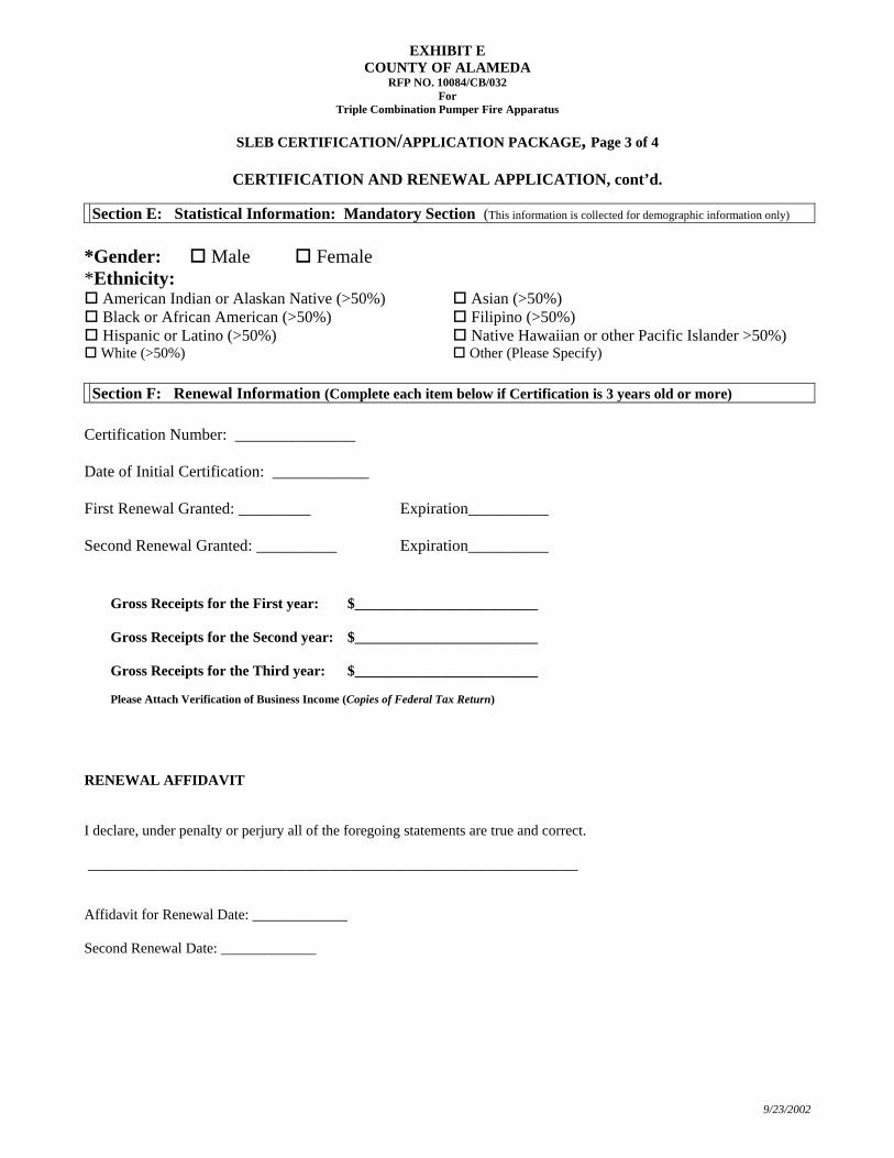
EXHIBIT E COUNTY OF ALAMEDA
RFP NO. 10084/CB/032 For
Triple Combination Pumper Fire Apparatus
SLEB CERTIFICATION/APPLICATION PACKAGE, Page 3 of 4
CERTIFICATION AND RENEWAL APPLICATION, cont’d.
Section E: Statistical Information: Mandatory Section (This information is collected for demographic information only)
*Gender: Male Female *Ethnicity:
American Indian or Alaskan Native (>50%) Asian (>50%) Black or African American (>50%) Filipino (>50%) Hispanic or Latino (>50%) Native Hawaiian or other Pacific Islander >50%) White (>50%) Other (Please Specify)
Section F: Renewal Information (Complete each item below if Certification is 3 years old or more)
Certification Number: _______________ Date of Initial Certification: ____________ First Renewal Granted: _________ Expiration__________ Second Renewal Granted: __________ Expiration__________
Gross Receipts for the First year: $_________________________ Gross Receipts for the Second year: $_________________________ Gross Receipts for the Third year: $_________________________ Please Attach Verification of Business Income (Copies of Federal Tax Return)
RENEWAL AFFIDAVIT
9/23/2002
I declare, under penalty or perjury all of the foregoing statements are true and correct. ___________________________________________________________________ Affidavit for Renewal Date: _____________ Second Renewal Date: _____________
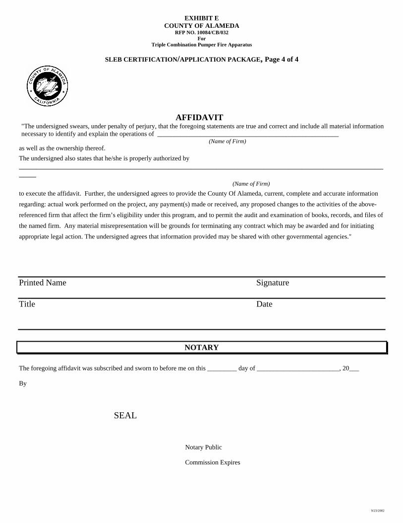
EXHIBIT E COUNTY OF ALAMEDA
RFP NO. 10084/CB/032 For
Triple Combination Pumper Fire Apparatus
SLEB CERTIFICATION/APPLICATION PACKAGE, Page 4 of 4
9/23/2002
AFFIDAVIT "The undersigned swears, under penalty of perjury, that the foregoing statements are true and correct and include all material information necessary to identify and explain the operations of _______________________________________________________
(Name of Firm) as well as the ownership thereof. The undersigned also states that he/she is properly authorized by _________________________________________________________________________________________
(Name of Firm)
to execute the affidavit. Further, the undersigned agrees to provide the County Of Alameda, current, complete and accurate information regarding: actual work performed on the project, any payment(s) made or received, any proposed changes to the activities of the above-referenced firm that affect the firm’s eligibility under this program, and to permit the audit and examination of books, records, and files of the named firm. Any material misrepresentation will be grounds for terminating any contract which may be awarded and for initiating appropriate legal action. The undersigned agrees that information provided may be shared with other governmental agencies."
Printed Name Signature Title Date
NOTARY The foregoing affidavit was subscribed and sworn to before me on this _________ day of _________________________, 20___ By SEAL
Notary Public Commission Expires
9/23/2002
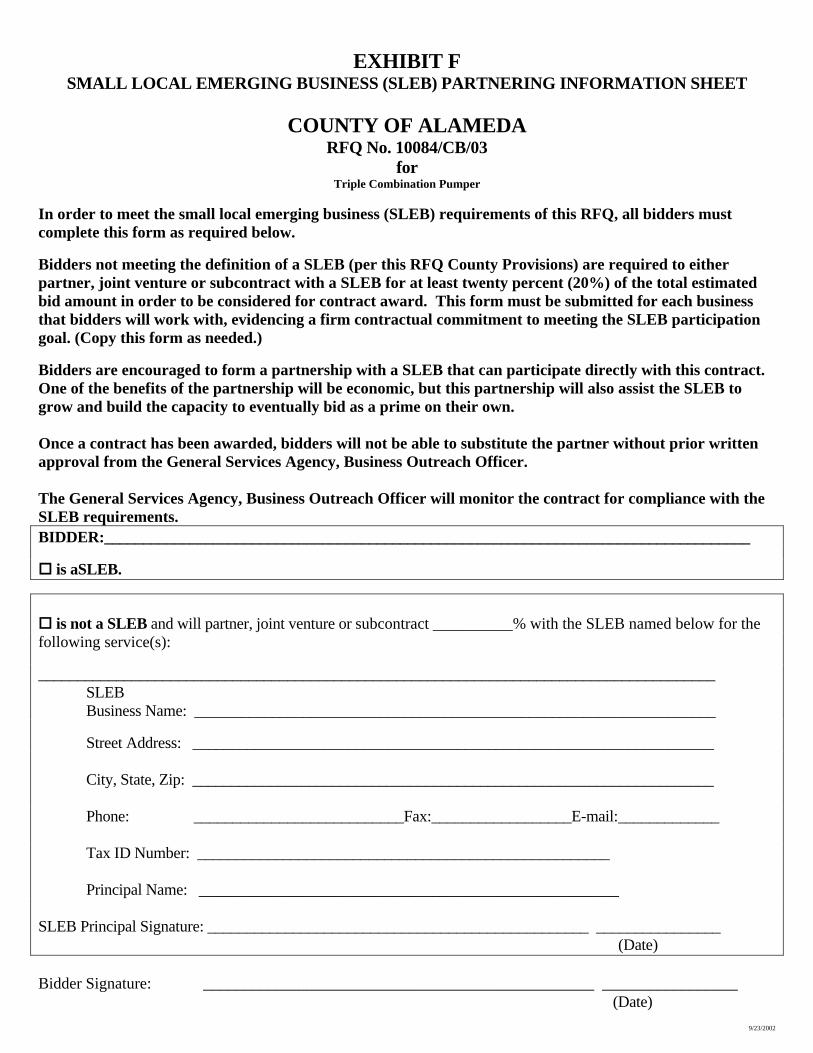
EXHIBIT F SMALL LOCAL EMERGING BUSINESS (SLEB) PARTNERING INFORMATION SHEET
COUNTY OF ALAMEDA
RFQ No. 10084/CB/03 for
Triple Combination Pumper In order to meet the small local emerging business (SLEB) requirements of this RFQ, all bidders must complete this form as required below.
Bidders not meeting the definition of a SLEB (per this RFQ County Provisions) are required to either partner, joint venture or subcontract with a SLEB for at least twenty percent (20%) of the total estimated bid amount in order to be considered for contract award. This form must be submitted for each business that bidders will work with, evidencing a firm contractual commitment to meeting the SLEB participation goal. (Copy this form as needed.) Bidders are encouraged to form a partnership with a SLEB that can participate directly with this contract. One of the benefits of the partnership will be economic, but this partnership will also assist the SLEB to grow and build the capacity to eventually bid as a prime on their own. Once a contract has been awarded, bidders will not be able to substitute the partner without prior written approval from the General Services Agency, Business Outreach Officer. The General Services Agency, Business Outreach Officer will monitor the contract for compliance with the SLEB requirements. BIDDER:___________________________________________________________________________________
is aSLEB.
is not a SLEB and will partner, joint venture or subcontract __________% with the SLEB named below for the following service(s): _______________________________________________________________________________________
SLEB Business Name: ___________________________________________________________________
Street Address: ___________________________________________________________________
City, State, Zip: ___________________________________________________________________
Phone: ___________________________Fax:__________________E-mail:_____________
Tax ID Number: _____________________________________________________ Principal Name: ______________________________________________________
SLEB Principal Signature: _________________________________________________ ________________ (Date)
Bidder Signature: _________________________________________________ _________________ (Date)

9/23/2002
EXHIBIT G
ALAMEDA COUNTY RFQ No. 10084/CB/032
for Triple Combination Pumper Fire Apparatus
REQUEST FOR PREFERENCE for
LOCAL BUSINESS and
SMALL AND LOCAL OR EMERGING AND LOCAL BUSINESS
IF YOU WOULD LIKE TO REQUEST THE LOCAL BUSINESS, SMALL AND LOCAL BUSINESS, OR
EMERGING AND LOCAL BUSINESS PREFERENCE COMPLETE THIS FORM AND RETURN IT WITH YOUR BID
A five-percent (5%) preference will be granted to Alameda County products or businesses on all sealed bids on contracts except with respect to those contracts which State law requires be granted to the lowest responsible bidder. An Alameda County business is a firm or dealer with fixed offices or distribution points located in and having a street address within the County and which holds a valid business license issued by the County or a city with the County. Alameda County products are those which are grown, mined, fabricated, manufactured, processed or produced within the County. In addition, a five percent (5%) preference, for a total bid preference of ten percent (10%), shall be granted (except as noted above) if the bidder is certified by the County as either a small and local or an emerging and local business. Check the appropriate (2 maximum) boxes and provide the requested information below.
Request for 5% local preference Request for 5% small and local preference OR Request for 5% emerging and local preference
Company Name:
Street Address:
Telephone Number:
Business License Number:
The Undersigned declares that the foregoing information is true and correct: Print/Type Name:
Title:
Signature:
Date:
9/23/2002
EXHIBIT I
COUNTY OF ALAMEDA RFQ No. 10084/CB/032
for Triple Combination Pumper Fire Apparatus
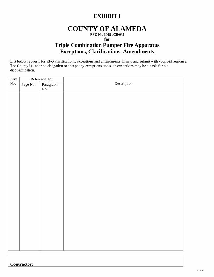
Exceptions, Clarifications, Amendments List below requests for RFQ clarifications, exceptions and amendments, if any, and submit with your bid response. The County is under no obligation to accept any exceptions and such exceptions may be a basis for bid disqualification.
Reference To: Item No. Page No. Paragraph
No.
Description
Contractor:
RFQ NO. 10084/CB/03 EXHIBIT M
RFQ VENDOR BID LIST
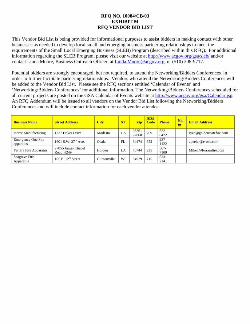
This Vendor Bid List is being provided for informational purposes to assist bidders in making contact with other businesses as needed to develop local small and emerging business partnering relationships to meet the requirements of the Small Local Emerging Business (SLEB) Program (described within this RFQ). For additional information regarding the SLEB Program, please visit our website at http://www.acgov.org/gsa/sleb/ and/or contact Linda Moore, Business Outreach Officer, at [email protected], or (510) 208-9717. Potential bidders are strongly encouraged, but not required, to attend the Networking/Bidders Conferences in order to further facilitate partnering relationships. Vendors who attend the Networking/Bidders Conferences will be added to the Vendor Bid List. Please see the RFQ sections entitled ‘Calendar of Events’ and ‘Networking/Bidders Conferences’ for additional information. The Networking/Bidders Conferences scheduled for all current projects are posted on the GSA Calendar of Events website at http://www.acgov.org/gsa/Calendar.jsp. An RFQ Addendum will be issued to all vendors on the Vendor Bid List following the Networking/Bidders Conferences and will include contact information for each vendor attendee.
Business Name Street Address City ST Zip Area Code.
Phone Num Email Address
Pierce Manufacturing 1237 Doker Drive Modesto CA 95351-2868 209 522-
0422 [email protected]
Emergency One Fire apparatus 1601 S.W. 37th Ave. Ocala FL 34474 352 237-
1122 [email protected]
Ferrara Fire Apparatus 27855 James Chapel Road #249 Holden LA 70744 225 567-
7100 [email protected]
Seagrave Fire Apparatus 105 E. 12th Street Clintonville WI 54929 715 823-
2141
RFQ NO. 10084/CB/03 EXHIBIT N
TRIPLE COMBINATION PUMPER SPECIFICATIONS
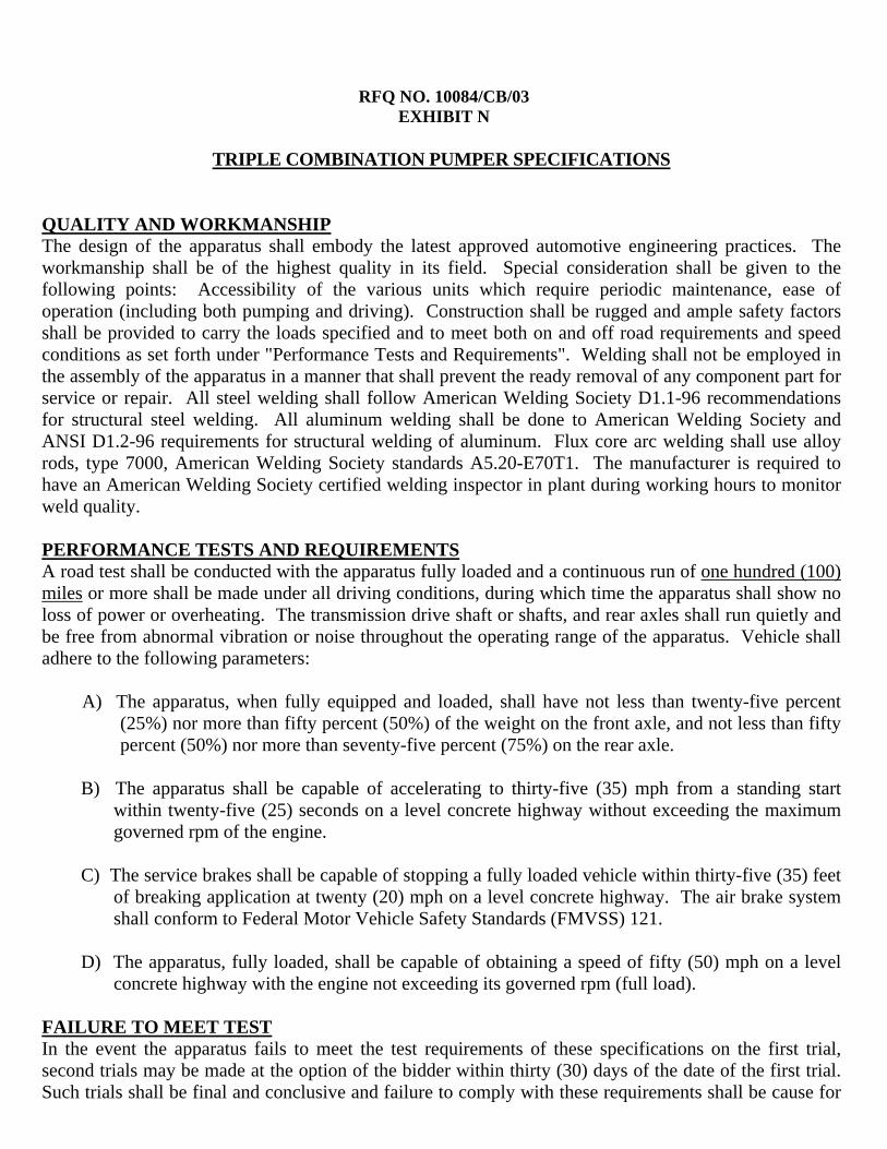
QUALITY AND WORKMANSHIP The design of the apparatus shall embody the latest approved automotive engineering practices. The workmanship shall be of the highest quality in its field. Special consideration shall be given to the following points: Accessibility of the various units which require periodic maintenance, ease of operation (including both pumping and driving). Construction shall be rugged and ample safety factors shall be provided to carry the loads specified and to meet both on and off road requirements and speed conditions as set forth under "Performance Tests and Requirements". Welding shall not be employed in the assembly of the apparatus in a manner that shall prevent the ready removal of any component part for service or repair. All steel welding shall follow American Welding Society D1.1-96 recommendations for structural steel welding. All aluminum welding shall be done to American Welding Society and ANSI D1.2-96 requirements for structural welding of aluminum. Flux core arc welding shall use alloy rods, type 7000, American Welding Society standards A5.20-E70T1. The manufacturer is required to have an American Welding Society certified welding inspector in plant during working hours to monitor weld quality.
PERFORMANCE TESTS AND REQUIREMENTS A road test shall be conducted with the apparatus fully loaded and a continuous run of one hundred (100) miles or more shall be made under all driving conditions, during which time the apparatus shall show no loss of power or overheating. The transmission drive shaft or shafts, and rear axles shall run quietly and be free from abnormal vibration or noise throughout the operating range of the apparatus. Vehicle shall adhere to the following parameters:
A) The apparatus, when fully equipped and loaded, shall have not less than twenty-five percent (25%) nor more than fifty percent (50%) of the weight on the front axle, and not less than fifty percent (50%) nor more than seventy-five percent (75%) on the rear axle.
B) The apparatus shall be capable of accelerating to thirty-five (35) mph from a standing start
within twenty-five (25) seconds on a level concrete highway without exceeding the maximum governed rpm of the engine.
C) The service brakes shall be capable of stopping a fully loaded vehicle within thirty-five (35) feet
of breaking application at twenty (20) mph on a level concrete highway. The air brake system shall conform to Federal Motor Vehicle Safety Standards (FMVSS) 121.
D) The apparatus, fully loaded, shall be capable of obtaining a speed of fifty (50) mph on a level
concrete highway with the engine not exceeding its governed rpm (full load). FAILURE TO MEET TEST In the event the apparatus fails to meet the test requirements of these specifications on the first trial, second trials may be made at the option of the bidder within thirty (30) days of the date of the first trial. Such trials shall be final and conclusive and failure to comply with these requirements shall be cause for
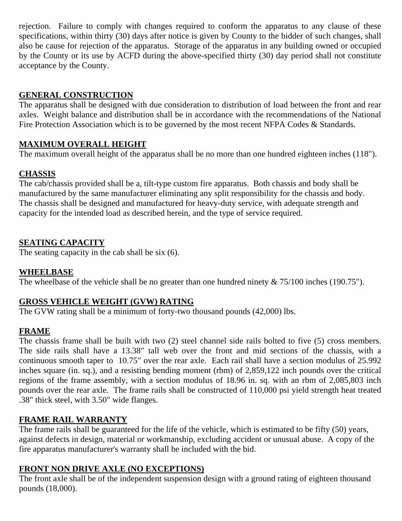
rejection. Failure to comply with changes required to conform the apparatus to any clause of these specifications, within thirty (30) days after notice is given by County to the bidder of such changes, shall also be cause for rejection of the apparatus. Storage of the apparatus in any building owned or occupied by the County or its use by ACFD during the above-specified thirty (30) day period shall not constitute acceptance by the County. GENERAL CONSTRUCTION The apparatus shall be designed with due consideration to distribution of load between the front and rear axles. Weight balance and distribution shall be in accordance with the recommendations of the National Fire Protection Association which is to be governed by the most recent NFPA Codes & Standards. MAXIMUM OVERALL HEIGHT The maximum overall height of the apparatus shall be no more than one hundred eighteen inches (118"). CHASSIS The cab/chassis provided shall be a, tilt-type custom fire apparatus. Both chassis and body shall be manufactured by the same manufacturer eliminating any split responsibility for the chassis and body. The chassis shall be designed and manufactured for heavy-duty service, with adequate strength and capacity for the intended load as described herein, and the type of service required. SEATING CAPACITY The seating capacity in the cab shall be six (6). WHEELBASE The wheelbase of the vehicle shall be no greater than one hundred ninety & 75/100 inches (190.75"). GROSS VEHICLE WEIGHT (GVW) RATING The GVW rating shall be a minimum of forty-two thousand pounds (42,000) lbs. FRAME The chassis frame shall be built with two (2) steel channel side rails bolted to five (5) cross members. The side rails shall have a 13.38" tall web over the front and mid sections of the chassis, with a continuous smooth taper to 10.75" over the rear axle. Each rail shall have a section modulus of 25.992 inches square (in. sq.), and a resisting bending moment (rbm) of 2,859,122 inch pounds over the critical regions of the frame assembly, with a section modulus of 18.96 in. sq. with an rbm of 2,085,803 inch pounds over the rear axle. The frame rails shall be constructed of 110,000 psi yield strength heat treated .38" thick steel, with 3.50" wide flanges. FRAME RAIL WARRANTY The frame rails shall be guaranteed for the life of the vehicle, which is estimated to be fifty (50) years, against defects in design, material or workmanship, excluding accident or unusual abuse. A copy of the fire apparatus manufacturer's warranty shall be included with the bid. FRONT NON DRIVE AXLE (NO EXCEPTIONS) The front axle shall be of the independent suspension design with a ground rating of eighteen thousand pounds (18,000).
Upper and lower control arms shall be used on each side of the axle. Upper control arm castings shall be made of 100,000 psi yield strength 8630 steel and the lower control arm casting shall be made of 55,000 psi yield ductile iron. The center cross members and side plates shall be constructed out of 80,000 psi yield strength steel. Each control arm shall be mounted to the center section using elastomer bushings. These rubber bushings shall rotate on low friction plain bearings and be lubricated for life. Each bushing shall also have a flange end to absorb longitudinal impact loads, reducing noise and vibrations. There shall be nine (9) grease fittings supplied, one (1) on each control arm pivot and one (1) on the steering gear extension.
A) The upper control arm shall be shorter than the lower arm so that wheel end geometry provides positive camber when deflected below rated load and negative camber above rated load.
B) Camber at load shall be zero (0) degrees for optimum tire life.
C) The kingpin bearing shall be of low friction design and be sealed for life.
D) Toe links that are adjustable for alignment of the wheel to the center of the chassis shall be
provided.
E) The wheel ends must have little to no bump steer when the chassis encounters a hole or obstacle.
F) The steering linkage shall provide proper steering angles for the inside and outside wheel, based
on the vehicle wheelbase.
i. The axle shall have third party certification in the following areas:Cramp angle – No less than 45 degrees. Front discharge or aluminum wheels shall not infringe on this cramp angle.
ii. Stopping Distance – independent front suspension axle shall stop sixty (60) feet shorter traveling at 60 MPH compared to a truck that is the same weight with a straight front axel and 15.00 rotors.
G) A single source supplier shall manufacture the front axle in the United States of America. Front
suspensions purchased and installed by a second party installer shall not be acceptable. Parts shall be readily available through the factory-authorized service center.
H) Bidder shall provide a user listing of twenty-five (25) Fire Departments where the Independent
Front Axle is currently in-service on a fire truck chassis. Included in the user listing shall be the name of the department, city, state, contact name, contact title, and phone number.
FRONT NON DRIVE AXLE WARRANTY The non drive axle system shall have a three (3) year parts and labor warranty. OIL SEALS The front axle wheel bearings shall be lubricated by oil-bath system with oil seals.
SHOCK ABSORBERS Heavy-duty telescoping shock absorbers (Gabriel) shall be provided on the front suspension. REAR DRIVE AXLE The rear axle shall be a Meritor™, Model RS-24-160, with a capacity of 24,000 pounds. REAR DRIVE AXLE WARRANTY The Meritor™ three (3) year parts and labor warranty shall be provided with this axle, plus an additional two (2) years of parts only coverage. Meritor™ shall also provide a one (1) year parts and labor warranty for wheel seals. The seal warranty shall apply to standard Meritor™ wheel seals and shall not apply to another specified seal. If other seals are specified, the warranty shall be parts only. TOP SPEED OF VEHICLE A rear axle ratio shall be furnished to allow the vehicle to reach an approximate top speed of sixty-four (64) to sixty-seven (67) MPH. OIL SEALS Oil seals shall be provided on the rear axle. FRONT SUSPENSION (NO EXCEPTIONS)
A) Front independent suspension shall be provided with a minimum ground rating of 18,000 pounds.
B) The independent suspension system shall be designed to provide maximum ride comfort. The
design shall allow the vehicle to travel at highway speeds over improved road surfaces, and at moderate speeds over rough terrain with minimal transfer of road shock and vibration to the vehicle's crew compartment.
Each wheel shall have torsion bar type springs. In addition, each front wheel end shall also have energy absorbing bounce bumpers to prevent bottoming of the suspension.
C) The suspension design shall be such that there is at least 10.00" of total wheel travel and a minimum of 3.75" before suspension bottoms.
D) A single-source supplier shall manufacture the front suspension in the United States of
America. Front suspensions purchased and installed by a second party installer shall not be acceptable. Parts shall be readily available through the factory authorized service center.
E) Bidder shall provide a user listing of twenty-five (25) fire departments where the independent
front suspensions are currently in service on a fire truck chassis. Included in the user listing shall be the name of the department, city, state, contact name, contact title, and phone number.
SUSPENSION, REAR Rear suspension shall be Reyco, Model 102AR, air ride with a ground rating of 24,000 pounds. The suspension has the following features:
A) Outboard vertical mounted heavy duty shock absorbers B) Adjustable torque and track rods
C) Heavy duty extra strength trailing beam D) Low rate air spring E) Dual weight control valves to compensate for weight difference.
ANTI-LOCK BRAKE SYSTEM The vehicle shall be equipped with a Wabco 4S4M, anti-lock braking system. The ABS shall provide a four (4) channel anti-lock braking control on both the front and rear wheels. It shall be a digitally controlled system that utilizes microprocessor technology to control the anti-lock braking system. Each wheel shall be monitored by the system. When any particular wheel begins to lockup, a signal shall be sent to the control unit. This control unit then shall reduce the braking of that wheel for a fraction of a second and then reapply the brake. This anti-lock brake system shall eliminate the lockup of any wheel. ANTI-LOCK BRAKE SYSTEM WARRANTY The Wabco ABS system shall come with a three (3) year or 300,000 mile parts and labor warranty provided by Meritor Wabco Vehicle Control Systems. FRONT BRAKES (NO EXCEPTIONS) The service brake system shall be full air type. The front brakes shall be Knorr/Bendix disc type with a 17.00” ventilated rotor for improved stopping distance. REAR BRAKES The rear brakes shall be Merritor disc operated with automatic slack adjusters. The axle manufacturer based on weight ratings shall determine rotor size. AIR COMPRESSOR, BRAKE SYSTEM The air compressor shall be a Bendix BA-921 with 15.8 cubic feet per minute output at 1250 RPM. BRAKE SYSTEM The brake system shall include:
A) Bendix-Westinghouse dual brake treadle valve with vinyl covered foot surface. B) A heated automatic moisture ejector on air dryer. C) Total air system capacity of 4,362 cubic inch. D) Two (2) air pressure gauges with red warning light and audible alarm, that activates when air
pressure falls below 60 psi. E) Spring set parking brake system. F) Parking brake operated by a Bendix-Westinghouse PP-1 control valve. G) A parking "brake on" indicator light on instrument panel. H) Bendix-Westinghouse SR-1 valve, in conjunction with a double check valve system, shall be
provided with an automatic spring brake application at 40 psi. I) Wabco System Saver 1200 air dryer.
GUARD OVER PARKING BRAKE KNOB A U-bolt type protective guard shall be installed over the "Parking Brake" knob to prevent accidental activation of the brake. BRAKE LINES Color coded nylon brake lines shall be provided. The lines shall be wrapped in a heat protective loom where necessary in the chassis.
AIR OUTLET One (1) air outlet shall be installed with a female coupling and shut off valve, located on the driver side of pump panel. This system shall tie into the "wet" tank of the brake system and include an 85 psi pressure protection valve in the outlet line to prevent the brake system from losing all air. A mating male fitting shall be provided with the loose equipment. ALL WHEEL LOCK-UP An all wheel lock-up system shall be installed which applies air to the front brakes and uses the spring brake at the rear. GUARD OVER ALL WHEEL LOCK-UP KNOB A U-bolt type protective guard shall installed over the "Front Wheel Lock" knob to prevent accidental activation of the brake. ISOLATED BRAKE RELEASE An additional air tank with 1454 cubic inch displacement shall be provided for an isolated emergency brake release. The control shall be located inside the cab within easy reach of the driver. GUARD OVER ISOLATED BRAKE RELEASE KNOB A U-bolt type protective guard shall installed over the "Emergency Brake Release" knob to prevent accidental activation of the release. ENGINE SHUTDOWN W/RESET An emergency engine shutdown, by means of incorporating a flapper over the engine air intake, shall be provided with a pneumatic push-to-activate control inside the cab. A protective guard shall be supplied to avoid unnecessary activation. The push-to-active control inside the cab can also be used to release the emergency shutdown, without having to tilt the cab. MANUAL MOISTURE EJECTORS
A) Four (4) manual moisture ejectors shall be installed in the brake system.
B) The moisture ejector shall be remote mounted on the driver side of vehicle, as close to the edge of vehicle as possible.
C) A loop shall be provided at the moisture ejector, to allow for ease of pulling the drain.
D) Each moisture ejector shall have a label directly under the ejector, stating air tank drain.
E) Nylon tubing, .38" diameter shall be routed from the air tank to the moisture ejector. The
nylon tubing shall be cover with protective split loom.
F) The moisture ejector (s) shall be provided on the left side of the vehicle under the forward most position of the body (engineer’s compartment on the body forward of left rear wheel).
AIR INLET
One (1) air inlet with male coupling shall be provided. It shall allow station air to be supplied to the apparatus brake system through a shoreline hose. The inlet shall be located on the driver side seat riser. A check valve shall be provided to prevent reverse flow of air. The inlet shall discharge into the "wet" tank of the brake system. A mating female coupling shall also be provided with the loose equipment. ENGINE
The chassis shall be powered by a Detroit Diesel electronically controlled engine as described below:
• Model: Series 60, 14.0L (855 cubic inches) • Rated Power: 475 bhp at 2100 rpm • Peak Torque: 1550 lb-ft at 1200 rpm • Governed Speed: 2100 rpm • Bore and Stroke: 5.24" x 6.61" • Number of Cylinders: Six (6) • Compression Ratio: 16.0:1
Standard equipment on the engine shall include the following: • Governor: Limiting speed type • Injectors: Cam operated, unit type, clean tip • Starting Motor: 12-volt • Turbocharger • Air To Air After cooled • Lube Oil Cooler • Lube Oil Filter: Full flow • Air Cleaner: Farr or equal • Fuel Filters: Dual, with check valve • Coolant Filter: Spin-on with shut off valves (precharged with coolant inhibitor)
ENGINE WARRANTY The engine shall come with a five (5) year or 100,000 mile warranty provided by the Detroit Diesel Corporation. ENGINE INSTALLATION CERTIFICATION (NO EXCEPTIONS) The fire apparatus manufacturer shall provide, at the time of delivery, a letter from the engine manufacturer stating they approve of the engine installation in the bidder's chassis. The approval of the engine installation shall be at full horsepower rating in a continuous duty application under all operating conditions, including road and pump. No type of automatic horsepower reduction feature shall be allowed. There shall be no exception to any portion of the engine installation certification. Nonconformance shall lead to immediate rejection of bid. EXHAUST SYSTEM The exhaust system shall be 5.00" diameter.
The exhaust shall exit on the right side ahead of the rear wheels. A heat deflector shield shall be provided where the tail pipe is routed under any side compartment. EXHAUST MODIFICATION FOR PLYMOVENT SYSTEM Exhaust pipe shall be brought out from under the body at a 90 degree angle from the truck. The tail pipe shall extend a minimum of 2.00" past the body, adaptable for the Plymovent system. There shall be a clearance of 4.00" completely around the pipe once past the side of the body. A stop shall be put on the tail pipe that shall prevent the nozzle from sliding too far up. EXHAUST MODIFICATION The tail pipe shall terminate on the passenger side of truck, directly under the front corner of body compartment, instead of the standard location, just to the front of rear wheel. FUEL SEPARATOR The engine shall be equipped with a Racor in-line spin-on fuel and water separator in addition to the engine fuel filters. This shall include a fuel reprime button. ENGINE HEATER A 1000 watt, 120 volt, immersion type engine heater shall be installed with the AC power inlet located to the rear of the driver's door. A warning light shall be provided on the cab instrument panel to indicate water in the fuel system. DIPSTICKS, COLOR CODED The engine oil and transmission oil dipstick handles shall be color coded, along with color coded labels. ENGINE START BUTTON An additional engine start button shall be provided next to the standard button on the cab instrument panel. HIGH IDLE A high idle switch shall be provided, inside the cab, on the instrument panel, that shall automatically maintain a preset engine rpm. A switch shall be installed, at the cab instrument panel, for activation/deactivation. The high idle shall be operational only when the parking brake is on and the truck transmission is in neutral. A green indicator light shall be provided adjacent to the switch. The light shall illuminate when the above conditions are met. The light shall be labeled "OK To Engage High Idle". COOLANT LINES Silicone hoses shall be used for all engine/heater coolant lines installed by the chassis manufacturer. Hose clamps shall be stainless steel "constant torque type" to prevent coolant leakage. They shall react to temperature changes in the cooling system and expand or contract accordingly while maintaining a constant clamping pressure on the hose. RADIATOR
The radiator and complete cooling system shall meet the NFPA cooling system standards and the engine manufactures guidelines at maximum load conditions. The radiator shall be mounted parallel with the charge air cooler to avoid drawing preheated air from the charge air cooler across the radiator fins, thus creating efficiencies in cooling performance. The fan shall be mounted directly to the cooling package and within a molded shroud to minimize the required fan tip clearances and to optimize airflow efficiencies and cooling performance. Cool air shall be drawn through the radiator by a belt driven fan. The fan shall be belt driven off the engine crank damper pulley utilizing a 1310 Series drive shaft and a 10 rib K-Section Poly V belt. The fan assembly shall be mounted directly to the radiator, and independent to the engine, which shall provide minimal fan tip to radiator shroud clearance resulting in optimum airflow. The fan assemble shall also have a Horton fan clutch incorporated into the upper mounting assembly. Clutch fan shall be automatic when the pump transmission is in "Road" and engaged constantly when in "Pump" position. The radiator shall have a sufficient capacity to exceed all cooling requirements specified by the engine manufacturer under all operating conditions. The system shall have a low coolant sight bulb mounted on the surge tank and an electronic controlled low coolant indicator mounted on the cab instrument panel. A remote surge and deaeration tank shall be provided to optimize the cooling system for all operating conditions. The cooling system shall be equipped to maintain a pressure at ten (10) psi for the maximum heat dissipation. The system shall have a drain cock located at the lowest point of the cooling system. Circulation baffles shall be furnished to prohibit hot air from the engine compartment from adversely affecting cooling system performance. The radiator shall be constructed with 175 tubes placed in three (3) rows with 16 fins per inch and bonded together by a patented "beta-weld" process for increased strength, longer life and solder-bloom corrosion protection. The completed core shall have a minimum 1200 square inches of cooling area. The entire cooling package assembly shall be mounted in a manner to prevent development of leaks caused by twisting or straining when the apparatus operates over uneven terrain. The radiator core shall be compatible with commercial antifreeze solutions. The engine and cooling system with hoses shall have a coolant capacity of 60 quarts. The cooling system shall be protected with an antifreeze solution to minus 30 degrees Fahrenheit. A grille assembly, consisting of perforated, polished stainless steel, shall be installed on the front center of the cab and serve as an air intake to the radiator. FUEL TANK A 50-gallon fuel tank shall be provided and mounted at rear of chassis. The tank shall be constructed of 12-gauge, hot rolled steel. It shall be equipped with swash partitions and a vent. A .75" drain plug shall be provided in a low point of the tank for drainage. A fill inlet shall be located on the driver's side of the body and be covered with a hinged, spring loaded, stainless steel door that is marked "Diesel Fuel Only".
A .50" diameter vent shall be provided running from top of tank to just below fuel fill inlet. The tank shall meet all FHWA (Federal Highways Act) 393.67 requirements including a fill capacity of 95% of tank volume. All fuel lines shall be provided as recommended by the engine manufacturer. AUXILIARY FUEL COOLING SYSTEM A supplementary fuel cooling system shall be provided to allow the use of water from the discharge side of the pump for cooling the chassis engine fuel. The heat exchanger shall be a cylindrical type and shall be a separate unit. The cooler shall operate any time the pump is discharging water and shall be plumbed to the master drain valve. DRIVELINE Drivelines shall be a heavy duty metal tube and be equipped with Spicer 1810 universal joints. The shafts shall be dynamically balanced before installation. A splined slip joint shall be provided in each driveshaft, slip joint shall be coated with Glide coat or equivalent. TRANSMISSION An Allison, model EVS 4000PR, electronic, torque converting, automatic transmission with retarder shall be provided. Two (2) PTO openings shall be located on left side and top of converter housing (positions 8 o'clock and 1 o'clock). A transmission temperature gauge, with red light and audible alarm, shall be installed on the cab instrument panel. The transmission retarder control shall be (RET7) activated by depressing a dedicated foot pedal located to the left of brake pedal. Retarder activation is variable from 0% to 100%. The retarder is also activated 100% by applying the brake pedal. The transmission shall have the 1600 ft. lb. torque (medium) spring setting for retardation force. The transmission retarder shall have a master "on/off" switch on the instrument panel. An indicator light shall be provided to notify the driver the transmission retarder is activated. Also, a red indicator light shall be provided to warn that the transmission is being overworked. The retarder shall be wired to the brake lights so they are energized when the retarder is slowing the vehicle down. The ABS system shall automatically disengage the auxiliary braking device, when required. TRANSMISSION, SHIFTER A five (5)-speed push button shift module shall be mounted to right of driver on console. Shift position
indicator shall be indirectly lit for after dark operation. The transmission ratio shall be: 1st - 3.51 to 1.00, 2nd - 1.91 to 1.00, 3rd - 1.43 to 1.00, 4th - 1.00 to 1.00, 5th - 0.74 to 1.00, R - 4.80 to 1.00. TRANSMISSION COOLER An external transmission oil cooler shall be provided. TRANSMISSION WARRANTY The transmission shall have a five (5) year/Unlimited mileage warranty covering 100% parts and labor. The warranty to be provided by Allison Transmission and not apparatus builder. STEERING Dual Sheppard M110 steering gears, with integral heavy-duty power steering, shall be provided. The power steering shall incorporate a Vickers V20NF hydraulic pump with integral pressure and flow control. The steering wheel shall be 18.00" in diameter, and capable of tilting and telescoping. TIRES Front tires shall be Goodyear radials 385/65R22.5, 18 ply G286 tread. The tires shall be mounted on Alcoa 22.50" x 12.25" polished aluminum disc-type wheels with a ten (10) stud, 11.25" bolt circle. Rear tires shall be four (4) Goodyear radials 12R22. 16 ply highway G159 tread. The tires shall be mounted on Alcoa 22.50" x 8.25" polished aluminum disc wheels with a ten (10) stud-11.25" bolt circle. LUG NUT COVERS Chrome plated lug nut covers shall be installed on all lug nuts. HUB COVERS (rear) A pair of stainless steel high hat hub covers shall be provided on rear axle hubs. CAB (NO EXCEPTIONS) The cab shall be designed specifically for the fire service and manufactured by the chassis builder. Construction of the cab shall consist of high strength 5052-H32 .125" aluminum welded to extruded aluminum framing. The cab shall be built by the apparatus manufacturer in a facility located on the manufacturer's premises. Cab shall be approximately 96.00" wide, with an approximate overall height of 108.00". Crew cab shall be of the totally enclosed design, with access doors constructed in the same manner as the driver and passenger doors. Cab shall be a full tilt design, allowing easy maintenance of the engine compartment. The engine shall be accessible when the cab is titled and the engine shall also be removable when the cab is tilted.
Provisions for checking the engine and transmission oil shall be provided on the engine tunnel and must be accessible without tilting the cab. Cab shall be isolated from the chassis inputs by four (4) rubber load cushions and shall be tilted by a hydraulic pump connected to two (2) cab lift cylinders. Cab shall then be locked down by a 2-point automatic locking mechanism that actuates after the cab has been lowered. Cab entrance steps shall be enclosed and automatically drop down when the door is opened. Both cab step assemblies shall be of simplistic and identical design. The steps shall be operated by a switch (air spool valve) on the cab door frame, which is connected to an air cylinder, that activates both the up and down operation of the steps. A dedicated air supply tank shall be furnished for the step air system, to assure an adequate air supply for the up and down activation. Each step, when in the stored position, shall be totally enclosed to protect the mechanisms from road debris and moisture. Each step assembly shall be designed in a three (3) step arrangement, with each step spaced no more than 16.00" apart, providing easy cab entry and egress. Each step surface shall be a minimum of 160 square inches. The step surface shall be constructed out of a non-slip material, that shall also be self-draining. Cab and crew cab doors shall be approximately 32.00" wide x 61.00" high. Crew cab doors shall be located on the side of the cab. Cab and crew cab doors shall be equipped with automotive type rubber, continuous perimeter bulb seal on the door opening to ensure a weather tight fit. Polished stainless steel scuff plates shall be installed on the inside of all cab doors, extending from the bottom of the door to 12.00" above the floor line. Cab doors shall be constructed of aluminum with a double pan design. All cab and crew cab entry doors shall contain a conventional roll down window. The upper area of each door shall be contoured into the roof and include a contoured tinted window feature, enhancing visibility and lighting. Flush mounted, chrome plated paddle type door handles shall be provided on the interior and exterior cab and crew cab doors. The door hinges shall be stainless steel piano type with a .25" pin. Cab and crew cab shall be designed to optimize room and allow complete visual and audio
communications between all fire fighters. The engine tunnel shall be constructed out of .125" aluminum and shall be tapered at the top to allow for more driver and passenger elbow room. The engine tunnel inside the cab shall not exceed 20.00" from the cab floor to the top of the engine tunnel to increase operational space within the cab. The width of the engine tunnel inside the cab shall not exceed 26.00" on the top tapered surface and 41.00" at the floor area. The engine tunnel shall also taper and narrow towards the rear as it extends into the crew cab area. The width of the engine tunnel on the top tapered surface at the rear shall not exceed 20.00", therefore providing optimum room for the fire fighters seated in the crew cab rear facing seats. The engine hood shall be insulated for protection from heat and sound. The noise insulation keeps the DBA level within the limits stated in the current NFPA series 1900 pamphlet. The driver and officer shall have a flat floor area measuring a minimum of 21.50" wide (door to engine tunnel) and 28.00" long (front to rear seat riser). The entire cab floor shall be at the same level both front and rear and shall be void of any step wells. The dimension from the back edge of the steering column to the driver's seat back (seat in rearmost position) shall be a minimum of 30.00". The dimension from the crew cab floor to the headliner shall have a minimum height of 55.00”. A 20.00" slip resistant handrail shall be provided adjacent to all door openings to assist with entrance into the cab. A rubber covered handrail shall be provided inside each front cab door adjacent to the door posts. Circular inner fender liners in the wheel wells shall be provided. Heavy duty black rubber mud flaps shall be installed on the cab behind the front wheels. The outside rear wall of the crew cab shall be covered with a bright aluminum tread plate panel. A contoured molded fiberglass housing shall be installed on the front of the cab. The housing shall be painted to match the cab. The headlight assemblies shall be recessed into the housings. A contoured molded fiberglass "eye brow" trim assembly shall be installed at the front roof line above the windshield. The eye brow shall be painted to match the cab roof. The marker lights shall be recessed into the eye brow. A large curved, safety glass windshield shall provide over 4,100 square inches of clear viewing area for enhanced visibility. The cab windshield shall be installed utilizing modern automotive techniques, which include bonding to the cab sheet metal with a urethane adhesive, and then trimmed in rubber.
Economical windshield replacement glass shall be readily available. Two (2) smoked Lexan sun visors shall be provided, one (1) above each windshield. Electric windshield wipers shall be provided that meet FMVSS and SAE requirements. One (1) control shall operate both wipers. The wiper control shall be two (2) speed (high and low) and feature an intermittent control. The control shall also have a "return to park" provision (toward center of cab). The wipers shall have a pantographic design for covering a large sweeping area. Each wiper shall be equipped with a washer that is actuated by the wiper control. Wash reservoir shall be able to be filled without raising the cab. AUXILIARY AIR COMPRESSOR An auxiliary air compressor shall be furnished to supply air for the cab step system. The air compressor shall be a 12-volt DC and wired directly to the batteries. The compressor shall have a rating of .5 CFM at 100 psi. The compressor shall insure fully automatic step operation at all times. CAB FLOOR The cab and crew cab flooring shall be constructed with bright aluminum tread plate. CREW CAB WINDOWS On each side of the crew cab, a window, with tinted glass, shall be provided. A contoured window, with tinted glass, shall also be provided above the side crew cab window and match the contoured windows in the cab doors. The rear wall of the crew cab shall have two (2) windows, each being 8.00" wide x 14.00" high. FENDER CROWNS Stainless steel fender crowns shall be installed at cab wheel openings. CONDUIT FOR RADIO INSTALLATION A section of 1.50” inside diameter flexible conduit for radio installation shall be provided. The conduit shall be installed from inside of the radio compartment below the officers seat to the microphone and speaker compartment. The microphone and speaker compartment is located on the left side front compartment bulkhead. CAB LIFT A hydraulic cab lift system shall be provided consisting of an electric powered hydraulic pump, dual lift cylinders, and necessary hoses and valves. The hydraulic pump shall have a manual override for backup in the event of electrical failure. Lift controls shall be located behind an access door on the passenger side, behind the bumper. Cab shall be locked down by a two (2)-point automatic spring loaded hook mechanism that actuates after the cab has been lowered.

The hydraulic cylinders shall be equipped with a velocity fuse which protects the cab from accidentally descending when the control is located in the tilt position. LABEL, CAB LIFT FLUID LEVEL A label which states "Cab Lift Fluid Level - Full Line" shall be provided on the hydraulic fluid reservoir. The reservoir shall also be provided with a vinyl stripe affixed to the reservoir at the full line. The full line shall be provided when the cab is in the tilted position, in order to prevent the tank from being overfilled.
INTERLOCK, CAB LIFT TO PARKING BRAKE The cab lift shall be interlocked to the parking brake. The cab tilt mechanism shall be active only when the parking brake is set and the ignition switch is in the on position, if the parking brake is released the cab tilt mechanism shall be disabled. MIRRORS Deluxe, full length west coast stainless steel mirrors with a 6.00" x 16.00" flat section shall be mounted on cab doors, one (1) on each side. CONVEX MIRRORS A 10.00" diameter round convex mirror shall be installed below each west coast mirror head. BUMPER A one (1) piece, ten (10) gauge, 304-2B type polished stainless steel bumper, a minimum 10.00" high shall be attached to a bolted modular extension frame constructed of 50,000 psi tensile steel "C" channel mounted directly behind it to provide adequate support strength. The bumper shall be extended 13.00" from front face of cab. Documentation shall be provided to show that the options selected have been engineered for fit-up and approval for this modular bumper extension. A chart shall be provided to indicate the option locations and shall include, but not be limited to the following options: air horns, mechanical sirens, speakers, hose trays (with hose capacities), winches, lights, discharge and suction connections. GRAVEL PAN A gravel pan, constructed of bright aluminum tread plate, shall be furnished between the bumper and cab face. The gravel pan shall be properly supported from the underside to prevent flexing and vibration of the aluminum tread plate. HOSE TRAY (right side) A hose tray shall be placed in the right side of the extended bumper. The tray shall have a capacity of 75' of 1.50" double jacket cotton-polyester hose. Black rubber grating shall be provided at the bottom of the tray. Drain holes shall be provided. TOW EYES Two (2) chromed steel tow eyes shall be installed under the bumper and attached to the front frame members. The inner and outer edges of the tow eyes shall have a 0.25” radius.
The tow eyes shall be designed and positioned to allow up to a 6,000 pound straight horizontal pull in line with the centerline of the vehicle. The tow eyes shall not be used for lifting of the apparatus. CAB INTERIOR The cab instrument panel shall be padded and covered with 46 ounce, leather grain vinyl, resistant to oil, grease and mildew. The door panels shall be covered with a high impact ABS plastic. The cab dash fascias shall be a wrap-around design to provide easy access of controls and shall be constructed out of high impact ABS plastic. The headliner shall be installed in both forward and rear cab sections. Headliner material shall be vinyl. A sound barrier shall be part of its composition. Material shall be installed on aluminum sheet and securely fastened to interior cab ceiling. Forward portion of cab headliner shall provide easy access for servicing electrical wiring or for other maintenance needs without removing the entire unit. CAB INTERIOR UPHOLSTERY The cab interior upholstery shall be black leather grain vinyl. INTERIOR PAINT (Cab) The cab interior metal surfaces shall be painted red to match the cab exterior color. SEAT, DRIVER A Seats Inc. #911 Magnum 100 "knee-action" air-ride style seat with high-back shall be provided in the cab for the driver. The seat shall have 3.00" of height adjustment, in addition to the "knee-action" suspension. The driver's seat shall be furnished with three (3)-point shoulder type seat belt. The seat belt shall be furnished with automatic retractor. Extension shall be provided with the seat belt so the male end can be easily grasped and the female end easily located while sitting in a normal position. DRIVER SEAT ACCESS DOOR A vertically hinged access door, constructed of smooth aluminum, shall provide access to the compartment located under the driver air ride seat. The door shall include a chrome plated lift and turn latch. SEAT, OFFICER A Seats Incorporated 911 "scissors-action" air-ride style Concept SCBA seat shall be provided in the cab for the officer. The SCBA cavity shall be adjustable front to rear in 0.50" increments to accommodate different size SCBA bottles. Moving the SCBA cavity shall be accomplished by unbolting, relocating and rebolting in the desired location.
The officer seat shall be furnished with three point shoulder type seat belts. The seat belts shall be furnished with automatic retractors. Extensions shall be provided with the seat belts so the male end can be easily grasped and the female end easily located while sitting in a normal position. RADIO COMPARTMENT, OFFICER A radio compartment shall be provided under the officer's seat. The inside compartment dimensions shall be 14.88" deep x 13.00" across x 5.25" high. A vertically hinged door, with hinge to the inside, shall be provided on the front side for access. The hole in the back of the compartment is to be slotted all the way to the bottom, so the box can be removed without disconnecting the wires from the radios. There shall be a U-shaped notch at the rear of the compartment for wire access. The compartment shall be constructed of smooth aluminum and painted to match the cab interior. SEATING (Rear Facing Crew Cab) Two (2) rear facing Seats Incorporated 911 Concept SCBA Seats shall be provided in the outboard positions in crew cab. The SCBA cavity in each seat shall be adjustable front to rear in 0.50" increments to accommodate different size SCBA bottles. Moving the SCBA cavity shall be accomplished by unbolting, relocating and rebolting in the desired location. Seats shall be furnished with three point shoulder type seat belts. The seat belts shall be furnished with automatic retractors. Extensions shall be provided with the seat belts so the male end can be easily grasped and the female end easily located while sitting in a normal position. SCUFFPLATE, REAR FACING SEAT RISER An aluminum 4-way scuffplate shall be provided on the rear facing seat riser, vertical surface. Scuffplate shall be 8.00" high x 90.00" wide. A 1.00" x 2.00" stainless steel angle along the entire top edge shall also be provided. SEATING (forward facing crew cab) Two (2) forward facing, Seats Incorporated 911 non-SCBA, seats shall be provided in the center positions, against the cab rear wall. The seats shall consist of two (2) separate high back cushions and two (2) separate seat bottom cushions. Each seat bottom cushion shall be mounted with a hinge on the front side to allow access to the seat riser compartment. A butterfly latch shall be provided between the seats, and a gas cylinder shall be provided to hold the seats up when required. Seats shall be furnished with three (3) point shoulder type seat belts. The seat belts shall be furnished with automatic retractors. Extensions shall be provided with the seat belts so the male end can be easily grasped and the female end easily located while sitting in a normal position. LOUVERS, FORWARD FACING SEAT RISER Louvers shall be provided at each side of the forward facing seatriser.
SEAT UPHOLSTERY All seat upholstery shall be 46 oz. leather grain black vinyl resistant to oil, grease and mildew. The backrest bolsters on SCBA type seats and top outside edges of bottom cushion shall be lined with Tuff-Tex material for long lasting durability. AIR BOTTLE HOLDERS All SCBA type seats in the cab shall have a Ziamatic, model KD-UH-5-SFCRS SCBA holder with a "knock-down" bracket and collision restraint holding strap mounted in each backrest. The bracket shall be adjustable up and down by simply unbolting, relocating and rebolting in desired position. The two (2) inboard forward facing crew cab seats shall be split apart approximately 8.00" to provide additional room at each seat position. CAB WARRANTY The bidder shall furnish a ten (10) year cab warranty. The warranty shall cover defects in design or workmanship in the cab tubular support and mounting supports and other cab structural components identified in the specifications. A copy of the warranty shall be submitted with the bid. (no exceptions) FOLD DOWN STEP WARRANTY The bidder shall furnish a two (2) year fold down step warranty. The warranty shall cover defects in material and workmanship for the fold down steps. A copy of the warranty shall be submitted with the bid. (no exceptions) ENGINE COMPARTMENT LIGHT An engine compartment light shall be installed under the engine hood, of which the switch is an integral part. Light shall have a .125" diameter deep hole in its lens to prevent moisture retention. CAB INTERIOR LIGHTING Auxiliary lights shall be provided in the cab and consisting of:
• One (1) Weldon, Model 8081-6978-68, Red/Clear dome light located on the officer side, controlled by the following:
- Clear forward light controlled by the door switch and the lens switch. - Red rearward light controlled by the lens switch.
• Two (2) Adjustable Map Lights: With switches mounted on the cab ceiling • A Courtesy Light at Each Door Opening: Controlled by automatic door switches.
CREW CAB INTERIOR LIGHTING Auxiliary lights shall be provided in the crew cab and consist of:
• Four (4) Weldon, Model 8081-6978-68, Red/Clear dome lights located each side, controlled by the following:
- Clear forward lights controlled by the door switch and the lens switch. - Red rearward lights controlled by the lens switch.
• A courtesy light at each door opening, controlled by automatic door switches CAB HEATER There shall be a 40,000 BTU heater in the cab located below the right side cab dash. The heater/defroster ventilation shall be built into the design of the cab dash instrument panel. The heater ducts shall be vented in a manner to provide heat directed towards the officer and the driver. The defroster ducts shall be designed to provide maximum defrosting capabilities for the windshield. Adjustable defroster louvers
shall be provided for directing airflow to the side cab door windows. Heater defroster controls shall be located on the cab dash within easy reach of the driver. AIR CONDITIONING A high performance air conditioning system shall be furnished inside the cab and crew cab. The air conditioning system shall perform as follows: In 100 degree Fahrenheit ambient temperature, with 50 percent relative humidity and at 1200 engine RPM, the cab and crew cab shall cool down to 72 degrees Fahrenheit within 30 minutes. Actual test results from the manufacturer of the air conditioning system verifying this performance requirement shall be submitted with the bid. A 12.6 cubic inch compressor shall be installed on the engine. A roof mounted condenser with adequate BTU to meet the performance specification, shall be installed on the cab roof. Condenser mounting below the cab or body is not acceptable. Two (2) evaporator units shall be installed in the cab, located in the following locations:
• One (1) in the cab dash, just to the front of the officer • One (1) in the crew cab, mounted to ceiling
The evaporator units shall have an adequate BTU rating to meet the performance specifications. The air conditioning system shall have adjustable air outlets incorporated into the cab dash at both the driver and officer positions. The evaporator unit in the crew cab shall have adjustable air outlets located directly on the evaporator unit. The air conditioner refrigerant shall be R-134A, installed by a certified technician. INTERIOR CAB INSULATION The cab and crew cab walls shall be insulated with 2.00" insulation where possible and the roof with 1.00" insulation to aid in cooling. The insulation shall be covered with a vinyl liner or a metal panel painted to match the interior. ROOF VENTS Two (2) power roof vents shall be installed in the crew cab for fresh air ventilation. CAB INSTRUMENTATION Instrument panel controls and switches shall be identified as to function by imprinted word(s) adjacent to each item. Actuation of the headlight switch shall illuminate ("back-lite") wording for after dark operation. Turn signal and high beam headlight indicator lights shall also be provided. To avoid confusion, warning indicators shall be (where possible) the "dead front" type, meaning the warning light and word identification of same does not show up unless it is necessary. The built-in emergency light switch panel shall have a red master switch plus individual switches for selective
control. The switch panel shall be located in the "overhead" position above the windshield on the driver''s side to allow for easy access. Switches shall be rocker type with an indicator light, which is an integral part of the switch. Instrument panel gauges, vehicle lights and other electrical accessories shall use proper size wiring to accommodate expected current load. Wiring shall meet SAE J-1128 specifications for high temperature (250 degrees Fahrenheit min.) conditions and be color, number and function coded. Cab instruments and controls shall be conveniently located within the forward cab section. Gauges and emergency vehicle switches shall be installed on removable panels for ease of service. The following gauges and controls shall be furnished:
• Speedometer/Odometer: Electric • Tachometer: Electric • Hourmeter for Engine • Engine Oil Pressure Gauge: Red warning indicator light and audible alarm • Engine Coolant Temperature Gauge: Red warning indicator light and audible alarm • Automatic Transmission Oil Temperature Gauge: Red warning indicator light and audible alarm • Two (2) Air Pressure Gauges: Individual low air pressure warning indicator lights (red) and
audible alarm • Voltmeter: Two (2) stage low or high voltage warning indicator light and audible alarm • Low Coolant Warning Indicator Light: Amber and audible alarm • Stop Engine Warning Indicator Light: Red and audible alarm (electronic engines only) • Check Engine Warning Indicator Light: Amber and audible alarm (electronic engines only) • Fuel Gauge: Two (2) stage low fuel warning indicator light (amber) with audible alarm • Ignition Switch: Green ignition on indicator light • Push Button Engine Start Control Switch • Heater and Defroster Controls • Headlight Switch • Self Canceling Turn Signal Switch (arm) • Headlight Dimmer and Hazard Switch: Incorporated into turn signal arm • Emergency Warning Light Control Panel • Parking Brake Control: Red parking brake on indicator light • Horn Button Control: Center of steering wheel • Control Switch to Manually Check Cab and Operator's Panel Warning Indicators. • High Air Restriction Warning Indicator Light (electronic). • Ammeter. • An electronic alarm shall sound any time the cab is being raised or lowered. The alarm shall be
provided at the driver's side battery box.
INDICATOR LIGHTS FOR HORN SELECTOR SWITCH Indicator lights shall be installed on the instrument panel to show the air horn/electric horn selector switch location. RADIO WITH CD PLAYER A Panasonic AM/FM cassette stereo radio shall be included with the minimum following specifications:
• Bass/treble controls.
• Alphatuner V. • 18 FM channels and 6 AM channels preset with preset scan. • Auto preset memory followed by auto scan. • FM Optimizer (FMO), Adaptive FM Front End (AFE), and Impulse Noise. • AM Usable Sensitivity - 28dB. • FM Usable Sensitivity - 12dBf. • 50dB Quieting Sensitivity - 17dBf. • Alternate Channel Selectivity - 75dB. • Stereo Separation (1kHz) - 35dB.S/N Ratio (FM mono) - 70dB. • Fixed DIN. • Built-in quartz clock.
CD Player: • Auto reverse • Wow & Flutter (WRMS) - 0.12% • Frequency Response (N/A+/- 3dB) - 35Hz - 14kHz • S/N Ratio - 52dB
RADIO WITH CD PLAYER A Panasonic AM/FM stereo radio shall be provided. The compact disc stereo/radio shall be mounted within reach of the officer. The quantity and location of the speakers shall be one (1) pair of 5.25” speakers located in the cab and one (1) pair of 5.25” speakers located in the crew cab. The type and location of the antenna shall be a side-mounted antenna located on the passengers side of the cab.
Amplifier:
• Max. Power Output – 15 Watts per speaker, 4 speakers max. The radio cassette player shall be mounted within reach of the officer. The quantity and location of the speakers shall be one (1) pair of 5.25" speakers located in the cab and one (1) pair of 5.25" speakers located in the crew cab. The type and location of the antenna shall be a side-mounted antenna located on the passenger's side of the cab. ELECTRICAL POWER CONTROL SYSTEM A compartment shall be provided in or under the cab to house the vehicles electrical power and signal circuit protection and control components. The power and signal protection and control compartment shall contain circuit protection devices, power control devices, and a programmable logic controller. Power and signal protection and control components shall be protected against corrosion, excessive heat, excessive vibration, physical damage and water spray. Serviceable components shall be readily accessible.
Circuit protection devices, which conform to SAE standard, shall be utilized to protect each circuit. All circuit protection devices shall be sized to prevent wire and component damage when subjected to extreme current overload. General protection circuit breakers shall be Type-I automatic reset (continuously resetting) and conform to SAE J553 or J258. PTO power circuits shall be protected by Type III manual reset non-cycling circuit breakers conforming to SAE J553 or J258 which remain open until manually reset. When required, automotive type fuses conforming to SAE J554, J1284, J1888 or J2077 shall be utilized to protect electronic equipment. Power control relays and solenoids shall have a direct current (dc) rating of 125 percent of the maximum current for which the circuit is protected. A microprocessor based programmable logic controller shall be utilized to control safety interlocks and vehicle system status indicators. In addition to visual status indicators, the logic controller shall activate audible alarms designed to provide early warning of problems before they become critical. The programmable logic controller shall include the following attributes:
• On-board self-diagnostic input status indicators • Automatic self-test on startup with provision for manual activation • Eliminate control logic relays wherever possible • Provide logic control for NFPA 1901 mandated safety interlocks and indicators • Utilize system integration to eliminate redundant wiring and components • Improve control system reliability by reducing relay and connector contacts • Optically isolated inputs to eliminate transient electrical interference • Customized control software programmed to reflect the vehicles unique configuration • Field re-programmable to accommodate changes to the vehicles operating parameters • Fully documented hardware • Complete operating and troubleshooting manual
ELECTRICAL SYSTEM ON-BOARD DIAGNOSTICS On-board diagnostics indicators shall be provided to support rapid troubleshooting of the electrical power and signal system. The diagnostic indicators shall be located in a readily accessible area. A complete troubleshooting guide shall be provided with the vehicle to assist with interpretation of the diagnostic signals. INDICATOR LIGHT AND ALARM PROVE-OUT A system shall be provided which shall automatically test indicator lights and alarms located on the cab instrument panel when the ignition switch is activated. Provisions shall be provided to allow a manual retest when the ignition switch is "on" and before the parking brake is released or the split-shaft PTO is engaged. VOLTAGE MONITOR SYSTEM A voltage monitor system shall be provided to indicate the status of each battery system connected to the vehicles electrical load. The monitor system shall provide visual and audio warning when the system voltage is above or below optimum levels. Two (2) alarms stages shall be provided. The first stage shall activate intermittently if the system falls below 11.8 vdc or rises above 15 vdc. The second stage alarm shall activate continuously if the system voltage falls below 11.3 vdc or rises above 16 vdc. Input voltages shall be conditioned to avoid nuisance
alarms. POWER AND GROUND STUD A 12-volt power stud and a grounding stud shall be provided in the electrical component compartment for 2-way radio equipment. EMI/RFI PROTECTION The electrical system proposed shall include means to control undesired electromagnetic and radio frequency emissions. State of the art electrical system design and components shall be used to insure radiated and conducted EMI (electromagnetic interference) and RFI (radio frequency interference) emissions are suppressed at their source. The apparatus proposed shall have the ability to operate in the electromagnetic environment typically found in fire ground operations. The contractor shall be able to demonstrate the EMI and RFI testing has been done on similar apparatus and certifies that the vehicle proposed meets SAE J551 requirements. EMI/RFI susceptibility shall be controlled by applying immune circuit designs, shielding, twisted pair wiring and filtering. The electrical system shall be designed for full compatibility with low level control signals and high powered 2-way radio communication systems. Harness and cable routing shall be given careful attention to minimize the potential for conducting and radiated EMI-RFI susceptibility. BATTERY SYSTEM Six (6) Delphi 12 volt, 700 CCA, 180 reserve capacity, high cycle, maintenance-free group 31 batteries with a system rating of 4200 CCA at 0 degrees Fahrenheit and 1080 minutes of reserve capacity. The batteries shall be provided with threaded posts. BATTERY SYSTEM A single starting system shall be provided. An ignition switch and starter button shall be located on the instrument panel. MASTER BATTERY SWITCH A master battery switch, to activate the battery system, shall be provided inside the cab within easy reach of the driver. An indicator light shall be provided on the instrument panel to notify the driver of the status of the battery system. BATTERY COMPARTMENTS Batteries shall be placed on non-corrosive mats and be stored in well ventilated compartments located under the cab. Heavy-duty battery cables shall be used to provide maximum power to the electrical system. Cables shall be color coded. Battery terminal connections shall be coated with anti-corrosion compound. Battery solenoid terminal connections shall be encapsulated with semi-permanent rubberized compound. JUMPER STUDS
One (1) set of battery jumper studs with plastic color coded covers shall be installed behind an access door on the passenger side, behind the bumper. The access door shall be large enough to allow easy jumper cable access. A tag shall be provided for positive/negative terminals. BATTERY CHARGER A Kussmaul Autocharge 1000 battery charger with internal battery saver shall be provided. A display bar graph, indicating the state of charge, shall be provided on the driver side seat riser to show if charger is operating. The battery saver circuit shall be capable of supplying up to three (3) amps for external loads such as handlight or auxiliary radio batteries. The battery charger shall be wired to the 120-volt shoreline to activate automatically when power is connected. Battery charger shall be located in the crew cab seat riser. BATTERY CHARGER COVER A cover shall be fabricated and installed over the battery charger for protection. ALTERNATOR A C.E. Niehoff, model N1222-5, alternator shall be provided. It shall have a rated output current of 290 amp as measured by SAE method J56. Also it shall have a custom three (3)-set point voltage regulator, manufactured by C. E. Niehoff. The alternator shall be connected to the power and ground distribution system with heavy-duty cables sized to carry the full rated alternator output. CUSTOMER FURNISHED RADIO ANTENNAS There shall be three (3) customer furnished two-way radio antenna/s provided for installation. The antennas shall be located at the top of the cab as directed by ACFD at pre-construction. Cables shall be routed per photos and wiring diagram provided by ACFD to the Contractor at pre-construction. 12 VOLT OUTLETS (other than cab) There shall be one (1) 12 volt cigarette lighters provided on the apparatus, On the far right side of the dash panel on the passengers side. Wire direct to battery. 12 VOLT D.C. WIRING FOR ACCESSORIES 12 volt, 10 gauge wire shall be provided. A yellow power wire shall run from the battery switch to the passenger side overhead switch panel. It shall then continue to the area beneath the officers seat. A red power wire shall run from the battery to beneath the officers seat. It shall then continue to the passengers side overhead switch panel. Both sets or wires shall also include black ground wires. An accessory wiring diagram had been provided to engineering for their last unit. ROUTE CUSTOMER SUPPLIED CABLES Fire apparatus builder shall install two (2) customer supplied six (6) conductor David Clark intercom cables. The cables shall run from under the officer's seat to the officer's overhead switch panel area. Fire apparatus builder shall install customer power cables for the David Clark radio system and Motorola data cables. They shall be routed per the diagrams provided by ACFD at pre-construction. The David Clark cables that run to the pump panel shall run through conduit.
ELECTRONIC LOAD MANAGEMENT A Kussmaul electronic load management (ELM) system shall be provided that monitors the vehicles 12-volt electrical system, and automatically reduces the electrical load in the event of a low voltage condition and by doing so, ensures the integrity of the electrical system. The ELM shall monitor the vehicle's voltage while at the scene (parking brake applied). It shall sequentially shut down individual electrical loads when the system voltage drops below a preset value. Ten (10) separate electrical loads shall be controlled by the load manager. The ELM shall sequentially re-energize electrical loads as the system voltage recovers. The (ELM) shall also include a sequencer function which shall be used to enable channels 1-5, 6, 7, 8, 9, and 10. The (ELM) shall sequentially re-energize electrical loads as the system voltage recovers. SEQUENCER A warning light sequencer shall be provided that automatically turns the emergency lights on and off in a preset sequence. The sequencer shall be wired in conjunction with the emergency master light switch. When the switch is activated the lights shall be turned on in sequence one by one at 1/2 second intervals thereby protecting the alternator from power surges. When turned off the same process shall deactivate the warning lights in sequence to allow a gradual decrease in alternator output, rather than dumping the load. AMP DRAW REPORT (NO EXCEPTIONS) The bidder shall provide, at the time of bid and bid and delivery, an itemized print out of the expected amp draw of the entire vehicle's electrical system. The manufacturer of the apparatus shall provide the following bid and:
1) Documentation of the electrical system performance tests.
2) A written load analysis, which shall include the following: A) The nameplate rating of the alternator.
B) The alternator rating under the conditions specified per: NFPA 1901,1999 Edition, section 11-3.2.
C) The minimum continuous load of each component that is specified per: NFPA 1901, 1999 Edition, section 11-3.2.
D) Additional loads that, when added to the minimum continuous load, determine the total connected load.
E) Each individual intermittent load.
All of the above listed items shall be provided by the bidder per NFPA 1901, 1999 Edition, section 11-15.
EXTERIOR LIGHTING Exterior lighting shall meet or exceed Federal Department of Transportation, Federal Motor Vehicle Safety Standards and National Fire Protection Association requirements in effect at time of Quotation. Front headlights shall be halogen, rectangular shape, one (1) mounted in each front trim housing. The directional lights shall wrap-around on the outside corners of the trim housing. The headlight and directional lights shall be in the same assembly. Five (5) clearance lights and marker lights shall be installed in the "eye brow" trim above the windshields. The lights shall be Truck-Lite, model 21051Y, amber LED lamp kits. WARNING LIGHTS (Cab Face) A pair of red Whelen, Model 901000** strobe lights shall be provided on the front of the cab above the headlights. One (1) switch located on the instrument panel shall activate these lights. STEADY RED LIGHT There shall be one (1) light installed on the front of the cab Centered on the front of the cab. These lights shall be Whelen, Model 70R00FRR, red LED steady burning lights. These lights shall be activated by the same switch that activates the front lower zone warning lights. These lights shall be installed with flange. BACK-UP ALARM An ECCO, Model SA917-PM2, solid state electronic audible back-up alarm that actuates when the truck is shifted into reverse shall be provided. The device shall sound at 60 pulses per minute and automatically adjust its volume to maintain a minimum five (5) dba above surrounding environmental noise levels. MANUAL, FIRE APPARATUS PARTS Two (2) custom parts manuals for the complete fire apparatus shall be provided in hard copy with the completed unit. The manual shall contain the following:
• Job number • Part numbers with full descriptions • Table of contents • Parts section sorted in functional groups reflecting a major system, component, or assembly • Parts section sorted in Alphabetical order • Instructions on how to locate a parts
The manual shall be specifically written for the chassis and body model being purchased. It shall not be a generic manual for a multitude of different chassis and bodies. The service parts information included in this manual is also available on the factory website. The website offers additional functions and features not contained in this manual, such as digital photographs and line drawings of select items. The website also features electronic search tools to assist in locating

parts quickly. MANUALS, CHASSIS SERVICE Two (2) chassis service manuals containing parts and service information on major components shall be provided with the completed unit. The manuals shall contain the following sections:
• Job number • Table of contents • Troubleshooting • Front Axle/Suspension • Brakes • Engine • Tires • Wheels • Cab • Electrical, DC • Air Systems • Plumbing • Appendix
The manual shall be specifically written for the chassis model being purchased. It shall not be a generic manual for a multitude of different chassis and bodies. MANUALS, CHASSIS OPERATION Two (2) chassis operation manuals shall be provided. ELECTRICAL WIRING DIAGRAMS Two (2) electrical wiring diagrams, prepared for the model of chassis and body, shall be provided. WATER TANK Booster tank shall have a capacity of 500 gallons and be constructed of polypropylene plastic by United Plastic Fabricating, Incorporated. Tank joints and seams shall be nitrogen welded inside and out. Tank shall be baffled in accordance with NFPA Bulletin 1901 requirements. Baffles shall have vent openings at both the top and bottom to permit movement of air and water between compartments. Longitudinal partitions shall be constructed of .38" polypropylene plastic and shall extend from the bottom of the tank through the top cover to allow for positive welding. Transverse partitions shall extend from 4.00" off the bottom of the tank to the underside of the top cover. All partitions shall interlock and shall be welded to the tank bottom and sides. Tank top shall be constructed of .50" polypropylene. It shall be recessed .38" and shall be welded to the
tank sides and the longitudinal partitions. Tank top shall be sufficiently supported to keep it rigid during fast filling conditions. Construction shall include 2.00" polypropylene dowels spaced no more than 30.00" apart and welded to the transverse partitions. Two (2) of the dowels shall be drilled and tapped (.50" diameter, 13.00" deep) to accommodate lifting eyes. A sump that is 8.00" long x 8.00" wide x 6.00" deep shall be provided at the bottom of the water tank. Sump shall include a drain plug and the tank outlet. Tank shall be installed in a fabricated cradle assembly constructed of structural steel. Sufficient crossmembers shall be provided to properly support bottom of tank. Crossmembers shall be constructed of steel bar channel or rectangular tubing. Tank shall "float" in cradle to avoid torsional stress caused by chassis frame flexing. Rubber cushions, .50" thick x 3.00" wide, shall be placed on all horizontal surfaces that the tank rests on. Stops or other provision shall be provided to prevent an empty tank from bouncing excessively while moving vehicle. Mounting system shall be approved by the tank manufacturer. Fill tower shall be constructed of .50" polypropylene and shall be a minimum of 8.00" wide x 14.00" long. Fill tower shall be furnished with a .25" thick polypropylene screen and a hinged cover. An overflow pipe, constructed of 4.00" schedule 40 polypropylene, shall be installed approximately halfway down the fill tower and extend through the water tank and dump to the rear of the rear axle. 2.50" TANK DRAIN A 2.50" tank drain shall be installed with a 2.50" ball valve and tee handle control. The tee handle control shall be located underneath the forward section of the left front compartments and shall be properly labeled. The valve and control handle shall be installed in a manner that neither one could be hit during normal operation. WATER TANK WARRANTY The tank shall have a lifetime warranty.
BODY MODIFICATION FROM STANDARD The following body modifications shall be required for the installation of Reyco Air Suspension.
• Rear compartment shall be 4.00" shorter in depth • Rear platform and tow bar shall be 4.00" shorter in depth • Rear side compartments shall require a blister for the air bags • Special water tank mounting required.
HOSE BED The hose body shall be fabricated of 12-gauge galvanneal steel. The sides shall not form any portion of the fender compartments. Hose body width shall be minimum of 68.00" inside. Upper and rear edges of side panels shall have a double break for rigidity, a split tube fi-nish shall not be acceptable. The upper inside area of the rear hose bed beavertails shall be covered with polished stainless steel to prevent damage to painted surface when hose is removed. Flooring of the hose bed shall be removable aluminum grating with the top surface corru-gated to aid in hose aeration. The grating slats shall be a minimum of .50" x 4.50" with spacing between slats for hose ventilation. Hose bed shall accommodate 1,000' x 5.00", 500' x 2.50", 500' x 2.50", 200' x 1.75". Four (4) adjustable hosebed dividers shall be furnished for separating hose. Each divider shall be constructed of a .125" brushed aluminum sheet fitted and welded into a slotted, radiused extrusion along the top, bottom and rear edge. Divider shall be held in place by tightening two (2) bolts, one (1) at each end. Acorn nuts shall be installed on all bolts in the hose bed which have exposed threads. SHELF HOSE BED W/DIVIDER A removable shelf shall be provided for hose storage inside the hose bed. The shelf shall be mounted between the side wall and one (1) adjustable hose bed divider. The dimensions of the shelf shall be 14.25" wide with a 11.50" clear opening to the grating. A Velcro strap shall be provide at the rear from the bottom of the shelf to the top of the hose bed grating. HOSEBED CROSS DIVIDER A cross-divider shall be provided just behind the fill tower. The divider shall be bolted to the side sheet. BACKBOARD STORAGE COMPARTMENT A storage compartment for two (2) backboards, shall be provided above the aluminum hose bed cover on the drivers side. The compartment shall be constructed of bright aluminum treadplate. The compartment shall have a clear opening dimensions of approximately 5.00" high x 19.00" high x 74.00" long. A bright aluminum treadplate door shall be furnished at the rear for access to the backboards. A. cross-divider shall be provided just behind the fill tower. The divider shall be bolted to the side sheet. HOSE BED COVER A two (2) section hose bed cover, constructed of .125" bright aluminum treadplate shall be furnished. The cover shall be hinged with full length stainless steel piano hinge. The sides shall be slanted down
with the center of the cover supported by a stationary bridgework support. If access to water tank fill tower is blocked by the hose bed cover, then a hinged door shall be provided in it so that tank may be filled without raising cover doors. Chrome grab handles and four (4) gas filled cylinders shall be provided to assist in opening and closing the cover. A handrail is to be provided at the rear, in the center of the support, to assist in opening the cover. SPECIAL WIRING HOSEBED COVERS The hosebed cover shall be wired to the “Do Not Move Apparatus” light located in the cab and shall activate the light when either section of the hosebed cover is in the up position and the apparatus parking brake has been released. DO NOT MOVE APPARATUS LIGHT The hose bed cover shall be wired to the "Do Not Move Apparatus" light located in the cab and shall activate the light when either section of the hose bed cover is in the up position and the apparatus parking brake has been released. RUNNING BOARDS Running boards shall be fabricated of .125" bright aluminum treadplate. Each running board shall be supported by a welded 2.00" square tubing and channel assembly, which shall be bolted to the pump compartment substructure. Running boards shall be 12.75" deep and spaced .50" away from the pump panel. A splash guard shall be provided below the running board treadplate. TAILBOARD Rear step shall be constructed of .125" bright aluminum treadplate and spaced .50" from the body, as well as supported by a structural steel assembly. The rear tailboard shall be 22.00" deep. The exterior side shall be flanged down and in. Flanges shall not be notched. Entire rear surface between the beavertails shall be covered with bright aluminum treadplate to protect the painted surface when removing hose. Inside surface of each beavertail in the hose bed area shall be covered with polished stainless steel to protect the paint finish. The remaining inside surface of the beavertails shall be covered with bright aluminum treadplate. TOW BAR A tow bar shall be installed under the tailboard at center of truck.
Tow bar shall be fabricated of 1.00" CRS bar rolled into a 3.00" radius. Tow bar assembly shall be constructed of .38" structural angle. When force is applied to the bar, it shall be transmitted to the frame rail. Tow bar assembly shall be designed and positioned to allow up to a 30 degree upward angled pull of 17,000 pounds, or a 20,000 pound straight horizontal pull in line with the centerline of the vehicle. Tow bar design shall have been fully tested and evaluated using strain gauge testing and finite element analysis techniques. HOSE TRAY Two (2) hose trays shall be recessed one in each side running board. Capacity of the tray shall be 20.00' of 5.00" soft suction hose. Rubber matting shall be installed on the floor of the tray to provide proper ventilation. STRAP, VELCRO Two (2) hose trays shall have two (2) Velcro straps to secure items located in the hose tray. The location shall be one in each side running board. COMPARTMENTATION Body and compartments shall be fabricated of galvanneal galvannealsteel with a tensile strength of 52,000 psi. Side compartments shall be an integral assembly with the rear fenders. Circular fender liners shall be provided for prevention of rust pockets and ease of maintenance. Compartment flooring shall be 12-gauge and of the sweep out design, with the floor higher than the compartment door lip. The compartment door opening shall be framed by flanging the edges in 1.75” and bending out again .75” to form an angle. Drip protection shall be provided above the doors by means of bright aluminum extrusion, formed bright aluminum treadplate, or polished stainless steel. The top of the compartment shall be covered with bright aluminum treadplate rolled over the edges on the front, rear, and outward side. These covers shall have the corners “TIG” (Tungsten Inert Gas) welded. Side compartment covers shall be separate from the compartment tops. Front facing compartment walls shall be covered with bright aluminum treadplate. All screws and bolts which protrude into a compartment shall have acorn nuts on the ends to prevent
injury. UNDERBODY SUPPORT SYSTEM Due to the severe loading requirements of this pumper, a method of body and compartment support suitable for the intended load shall be provided. The backbone of the support system shall be the chassis frame rails, which is the strongest component of the chassis and designed for sustaining maximum loads. The support system shall include .375” thick steel vertical angle supports bolted to the chassis frame rails with .625” diameter bolts. Attached to the bottom of the steel vertical angles shall be horizontal angles, with gussets welded to the vertical members, which extend to the outside edge of the body. A steel frame shall be mounted on the top of these supports to create a “floating substructure”, which results in a 500 pound equipment support rating per lower compartment. The “floating substructure” shall be separated from the horizontal members with neoprene elastomer isolators. These isolators shall reduce the natural flex stress of the chassis from being transmitted to the body. The isolators shall have a broad load range, proven viability in vehicular applications, be of a fail safe design and allow for all necessary movement in three (3) transitional and rotational modes. The neoprene isolators shall be installed in a modified “V” three (3)-point mounting pattern to reduce the natural flex of the chassis being transmitted to the body. A design with body compartments hanging on the chassis, unsupported, shall not be acceptable. AGGRESSIVE WALKING SURFACE All exterior surfaces designated as stepping, standing, and walking areas shall comply with the required average slip resistance of NFPA section 13-7.3. LOUVERS All body compartments shall have a minimum of one (1) set of louvers stamped into a wall to provide the proper airflow inside the compartment and to prevent water from dripping into the compartment. These louvers shall be formed into the metal and not added to the compartment as a separate plate. TESTING OF BODY DESIGN Body structural analysis shall be fully tested. Proven engineering and test techniques such as finite element analysis, model analysis, stress coating and strain gauging shall be performed with special attention given to fatigue, life and structural integrity of the cab, body and substructure. The body shall be tested while loaded to its greatest in-service weight. The criteria used during the testing procedure shall include:
• Raising opposite corners of the vehicle tires 9.00", simulating the twisting a truck may experience when driving over a curb.
• Making a 90 degree turn while at 20 mph, simulating aggressive driving conditions. • Driving the vehicle at 35 mph on a "washboard" road. • Driving the vehicle at 55 mph on a smooth road. • Accelerating the vehicle fully, until reaching the approximate speed of 45 mph, on rough
pavement.
Evidence of actual testing techniques shall be made available upon request. BODY WARRANTY A copy of the fire apparatus manufacturer's warranty shall be included with the bid. The warranty shall state that the body shall be free of structural failures caused by defective design or workmanship for a warranty period of ten (10) years from the date the new vehicle is first delivered or 100,000 miles, whichever occurs first and that defective parts, under the warranty, shall be repaired or replaced without charge to the original purchaser. ENGINEER COMPARTMENT A transversed engineer compartment shall be provided ahead of the water pump. Compartment shall be 15.00" wide x 37.00" high x 66.00" deep. The door opening shall be 13.50" wide x 36.25" high. The clear height of the transverse section over the chassis frame rails shall be 21.00" high. Compartment shall be furnished with vertically hinged, lap style, compartment doors that have a "D" handle latch and positive door hold open device. COMPARTMENTATION, DRIVER’S SIDE A vertically hinged, single door compartment in the lower area ahead of the rear wheels shall be provided. The interior dimensions of this compartment shall be 22.50" wide x 34.63" high x 25.88" deep in the lower 26.00" of the compartment and 12.00" deep in the remaining upper portion. The depth of the compartment shall be calculated with the compartment door closed. The clear door opening of this compartment shall be 18.00" wide x 29.00" high. A positive door holder shall be furnished with this compartment. A horizontally hinged, single lift-up door compartment in the upper area ahead of the rear wheels shall be provided. The interior dimensions of this compartment shall be 58.00" wide x 32.88" high x 12.00" deep. The depth of the compartment shall be calculated with the compartment door closed. The clear door opening of this compartment shall be 53.50" wide x 28.25" high. The lift-up door shall be furnished with two gas-charged cylinders to assist in the opening of the door and to maintain the door in an open position. There shall be a field adjustable, three-position bracket mounted on the vertical side door opening that shall allow the door to be held open at 87°, 90°, or 93°. A horizontally hinged, single lift-up door compartment in the upper area behind the rear wheels shall be provided. The interior dimensions of this compartment shall be 65.63" wide x 32.88" high x 12.00" deep. The depth of the compartment shall be calculated with the compartment door closed. The clear door opening of this compartment shall be 53.50" wide x 28.25" high. The lift-up door shall be furnished with two (2) gas-charged cylinders to assist in the opening of the door and to maintain the door in an open position. There shall be a field adjustable, three-position bracket
mounted on the vertical side door opening that shall allow the door to be held open at 87°, 90°, or 93°. A vertically hinged, single door compartment in the lower area behind the rear wheels shall be provided. The interior dimensions of this compartment shall be 31.50" wide x 34.63" high x 25.88" deep in the lower 26.00" of the compartment and 12.00" deep in the remaining upper portion. The depth of the compartment shall be calculated with the compartment door closed. The clear door opening of this compartment shall be 30.00" wide x 29.00" high. A positive door holder shall be furnished with this compartment. COMPARTMENTATION, PASSENGER’S SIDE A vertically hinged, single door compartment ahead of the rear wheels shall be provided. The interior dimensions of this compartment shall be 22.50" wide x 33.63" high x 25.88" deep in the lower 26.00" of the compartment and 12.00" deep in the remaining upper portion. The depth of the compartment shall be calculated with the compartment door closed. The clear door opening of this compartment shall be 18.00" wide x 29.00" high. A positive door holder shall be furnished with this compartment. A vertically hinged, double door compartment behind the rear wheels shall be provided. The interior dimensions of this compartment shall be 31.50" wide x 33.63" high x 25.88" deep in the lower 26.00" of the compartment and 12.00" deep in the remaining upper portion. The depth of the compartment shall be calculated with the compartment door closed. The clear door opening of this compartment shall be 30.00" wide x 29.00" high. A positive door holder shall be furnished with this compartment. DOORS, SIDE COMPARTMENT All hinged compartment doors shall be lap style with double panel construction and shall be a minimum of 1.50" thick. To provide additional door strength, a "C" section reinforcement shall be installed between the outer and interior panels. Doors shall be provided with a closed cell rubber gasket around the surface that laps onto the body. A second heavy-duty automotive rubber molding with a hollow core shall be installed on the door framing that seals onto the interior panel, to ensure a weather resisting compartment. All compartment doors shall have polished stainless steel continuous hinge with a pin diameter of .25", that is bolted or screwed on with E-Zinc plated fasteners. (Hinges which are welded on shall not be acceptable.) All door lock mechanisms shall be fully enclosed within the door panels to prevent fouling of the lock in the event equipment inside shifts into the lock area. Doors shall be latched with recessed, polished stainless steel "D" ring handles and Eberhard 106 locks. To prevent corrosion caused by dissimilar metals, compartment door handles shall not be attached to outer door panel with screws. A rubber gasket shall be provided between the "D" ring handle and the door.
COMPARTMENTATION, REAR A vertically hinged, double door compartment above the rear tailboard shall be provided. Interior dimensions of this compartment shall be 40.00" wide x 40.63" high x 25.88" deep. Depth of the compartment shall be calculated with the compartment door closed. A louvered, removable access panel shall be furnished on the back wall of the compartment. Rear compartment shall be open into the rear side compartments. Clear door opening of this compartment shall be 34.50" wide x 36.00" high. Each of the vertically hinged compartment doors shall be provided with a positive door holder. DOORS, REAR COMPARTMENT All hinged compartment doors shall be lap style with double panel construction and shall be a minimum of 1.50" thick. To provide additional door strength, a "C" section reinforcement shall be installed between the outer and interior panels. Doors shall be provided with a closed cell rubber gasket around the surface that laps onto the body. A second heavy-duty automotive rubber molding with a hollow core shall be installed on the door framing that seals onto the interior panel, to ensure a weather resisting compartment. All compartment doors shall have polished stainless steel continuous hinge with a pin diameter of .25", that is bolted or screwed on with E-Zinc plated fasteners. (Hinges which are welded on shall not be acceptable.) A strip of dielectric isolation tape shall be provided between the hinge and door jamb. All door lock mechanisms shall be fully enclosed within the door panels to prevent fouling of the lock in the event equipment inside shifts into the lock area. Doors shall be latched with recessed, polished stainless steel "D" ring handles and Eberhard 106 locks. To prevent corrosion caused by dissimilar metals, compartment door handles shall not be attached to outer door panel with screws. A rubber gasket shall be provided between the "D" ring handle and the door. PARTITION, TRANSVERSE REAR COMPARTMENT Two (2) partitions shall be bolted in place to separate both side rear compartments from the rear tailboard compartment. REVERSE HINGED DOOR One (1) compartment door shall have the hinge at the rear of the door. The driver's side forward most low compartment will be reversed hinged. WORK LIGHTS, RECESSED IN COMPARTMENT DOOR A four (4) inch light shall be provided in the door pans of the driver's side lift-up compartments. The light shall be controlled by the automatic door switch. The total of two (2) compartment door pans shall be provided with a four (4) inch light.
PULL STRAP, DOORS Two (2) compartment doors shall be provided with pull straps. The pull straps will be located in the two (2) left side lift-up compartments. DOOR FRAME SCUFFPLATE Nine (9) Scuffplates shall be provided for the lower door frame of all compartment doors. Each scuffplate shall be polished stainless steel with a .38" lip down. KEYED LOCK(S) A keyed lock shall be furnished for Nine (9) compartment doors. The compartmentation, to have a keyed lock, shall be all compartment doors and will match key #1250. PULL-OUT TRAY There shall be one (1) slide-out tray with a minimum capacity of 500 pounds provided. The tray shall have a 2.00" lip on three (3) sides, with a .50" lip down on the front of the tray. Capacity rating shall be in the extended position. Slides shall be General Device ball bearing type, for ease of operation and years of dependable service. Automatic locks shall be provided for both the "in" and "out" positions. The trip mechanism for the pull out tray shall be located at the front of the tray for ease of use with a gloved hand. Tray location shall be Locate in the lower rear compartment on the left side of the body. Heavy-duty steel angle iron assembly shall support the body under the compartment floor. It shall be attached to the chassis frame for load transfer and to reduce stress on body. PLYWOOD LINING Plywood shall be installed on the back wall of two (2) compartments. The locations are, the two (2) driver's side lift-up compartments. The plywood shall be .75" exterior grade. Stainless steel retainers shall be used to mount the plywood. The plywood shall be sanded to a smooth finish and painted with a spatter paint to match the compartment interiors. ADJUSTABLE SHELVES There shall be five (5) shelves, with a minimum capacity of 215 pounds each. The shelf construction shall consist of .125" pan-shaped aluminum with 2.00" sides. Each shelf shall be infinitely adjustable by means of a threaded fastener, which slides in a track. The location shall be in each low compartment (total of 4), and one (1) in the tailboard compartment. MOUNTING TRACKS There shall be five (5) sets of tracks for mounting shelf(s) in each low compartment, and the tailboard compartment. These tracks shall be installed vertically to support the adjustable shelf(s). RUB RAIL Bottom edge of the side compartments shall be trimmed with a bright aluminum extruded rub rail.
Trim shall be 2.12" high with 1.38" flanges turned outward for rigidity. The rub rails shall not be an integral part of the body construction, which allows replacement in the event of damage. BODY FENDER CROWNS Stainless steel fender crowns shall be provided around the rear wheel openings. A rubber welting shall be provided between the body and the crown to seal the seam and restrict moisture from entering. A dielectric barrier shall be provided between the fender crown fasteners (screws) and the fender sheet metal to prevent corrosion. HOSE TROUGHS A trough for one (1) hard suction hose shall be installed above the passenger side compartments. Trough shall be constructed of galvanic steel and painted job color, V-shaped, and have Velcro/strap fasteners. Hose trough shall be adjustable up and down. Aluminum treadplate scuffplates shall be furnished, where couplings could hit the body while loading or unloading hose. HANDRAILS The handrails shall be 1.25" diameter anodized aluminum extrusion, with a ribbed design, to provide a positive gripping surface. Chrome plated end stanchions shall support the handrail. Plastic gaskets shall be used between end stanchions and any painted surfaces. Drain holes shall be provided in the bottom of all vertically mounted handrails. Handrails will be located as follows:
• Two (2) handrails shall be provided above each side pump panel. • One (1) vertical handrail, not less than 29.00" long, shall be located on each rear beavertail. • One (1) full width horizontal handrail shall be provided below the hose bed at the rear of the
apparatus. AIR BOTTLE STORAGE (Single bottle) A total of four (4) single air bottle compartments shall be provided. There will be two (2) air bottle compartments located on each side of the body in the fender area. The air bottle compartment shall be in the form of a round tube (7.63" diameter minimum) and of adequate depth to accommodate different size air bottles. Flooring shall be rubber lined and have a drain hole. A stainless steel door with a chrome plated latch shall be provided to contain the air bottle. A dielectric barrier shall be provided between the door hinge, hinge fasteners and the body sheet metal. GROUND LADDERS The following wooden ladders manufactured by Alaco shall be furnished:
• 24', two (2) section, wood, Series 2300-24 with zinc, yellow plated hardware • 14' roof, wood, Series 2304-14, with zinc yellow plated hardware. • 10’ wood, series 2305-10 folding ladder with zinc, yellow plated hardware shall be installed on
top of the ladder brackets with the latches reversed.
• The finish of all Alaco ladders shall be with Watco oil. • The ladder tips of the 24’ and 14’ ladders shall be painted gloss white per ACFD specifications. • The ladder bases of the 24’ and 14’ ladders shall be painted gloss black per the ACFD
specifications. These ladders shall be shipped directly to the customer from the manufacture of the ladders. FOLDING LADDER One (1) 10' wood, Series 2305-10 folding ladder with zinc, yellow plated hardware shall be installed on top of the ladder brackets with the latches reversed. This ladder shall be shipped directly to the customer from the manufacture of the ladder. LADDER BRACKETS The ladders shall be installed on the right side of the hose body in lined brackets and held in place by chrome plated, quarter-turn spring loaded clamps. The clamps shall be such that when the roof ladder is removed, the clamps can be moved a half turn to hold the extension ladder in place. The ladder brackets shall be adjustable up and down. SPACERS, NON-ABRASIVE, LADDER SUPPORTS Three (3) nonabrasive ladder support spacers shall be provided on the catwalk below the ladders. These spacers are to be evenly spaced and design to relieve stress from the ladder brackets and provide protection to the ladders from the aluminum treadplate on the catwalks. PIKE POLE,10' One (1) 10’ manufactured by with fiberglass handle shall be provided and located in the pike pole tube. DUO Safety One (1) 6’ long pike pole manufactured by DUO safety with a fiberglass “D” handle shall be provided and located in the pike pole tube. PIKE POLE STORAGE, D HANDLE Aluminum tubing shall be used for the storage of one (1) pike pole and shall be located inside of the ladder brackets. A full length slot shall be manufactured in the tube to store the D-Handle Pike Pole. If the head of a pike pole can come in contact with a painted surface, a stainless steel scuff plate shall be provided. PIKE POLE STORAGE Aluminum tubing shall be used for the storage of one (1) pike pole and shall be located inside of the ladder brackets. If the head of a pike pole can come in contact with a painted surface, a stainless steel scuff plate shall be provided. STEPS A step shall be provided on the front of each fender compartment. The front step shall be a bright finished folding type. REAR STEPS Bright aluminum treadplate corner steps shall be provided at the rear. All steps shall provide adequate surface for stepping.
STEP OVER REAR COMPARTMENT
A 10.00" deep, full width bright aluminum treadplate step shall be provided at the rear of the body. The step shall be located above the tailboard compartment. PUMP Pump shall be a Waterous CMUY, 1500 gpm, two (2) stage midship mounted centrifugal type. Pump shall be the class "A" type. Pump shall deliver the percentage of rated discharge at pressure indicated below:
- 100% of rated capacity at 150 psi net pump pressure. - 70% of rated capacity at 200 psi net pump pressure. - 50% of rated capacity at 250 psi net pump pressure.
Pump body shall be close-grained gray iron, bronze fitted, and must be horizontally split in two (2) sections for easy removal of the entire impeller shaft assembly (including wear rings). Pump shall be designed for complete servicing from the bottom of the truck, without disturbing the pump setting or apparatus piping. Pump case halves shall be bolted together on a single horizontal face, to minimize chance of leakage and facilitate ease of reassembly. No end flanges may be used. Discharge manifold of the pump shall be cast as an integral part of the pump body assembly, and shall provide a minimum of three (3) 3.50" openings, for flexibility in providing various discharge outlets for maximum efficiency. The 3.50" openings shall be located as follows: one (1) outlet to the right of the pump, one (1) outlet to the left of the pump, and one (1) outlet directly on top of the discharge manifold. Impeller shaft shall be stainless steel accurately ground to size, and supported at each end by oil or grease lubricated, anti-friction ball bearings, for rigid precise support. Impeller shall have flame plated hubs assuring maximum pump life and efficiency, despite any presence of abrasive matter in the water supply. Bearings shall be protected from water and sediment by suitable stuffing boxes, flinger rings, and oil seals. No special or sleeve type bearings shall be used. Pump shall be equipped with a self-adjusting, maintenance-free, mechanical shaft seal. The mechanical seal shall consist of a flat, highly polished, spring fed carbon ring that rotates with the impeller shaft. The carbon ring shall press against a highly polished stainless steel stationary ring that is sealed within the pump body. In addition, a throttling ring shall be pressed into the steel chamber cover, providing a very small clearance around the rotating shaft in the event of a mechanical seal failure. The pump performance shall not deteriorate, nor shall the pump lose prime, while drafting if the seal fails during pump operation.
Wear rings shall be bronze and easily replaceable to restore original pump efficiency and eliminate the need to replace the entire pump casing due to wear. PUMP TRANSMISSION (NO EXCEPTIONS) A "D" drop pump transmission shall be provided. Pump transmission shall be made of a three (3) piece, high tensile gray iron, horizontally split casing. Power transfer to pump shall be through a pressure lubricated, Morse HY-VO drive chain. Drive shafts shall be a minimum of 2.35" diameter hardened and ground alloy steel. All shafts shall be ball bearing supported. The case shall be designed as to eliminate the need for water cooling. AIR PUMP SHIFT (NO EXCEPTIONS) Pump shift engagement shall be made by a two (2) position sliding collar, actuated pneumatically (by air pressure, with a three (3) position air control switch located in the cab. A manual back-up shift control shall also be located on the drivers side pump panel. Two (2) indicator lights shall be provided adjacent to the pump shift inside the cab. One (1) green light shall indicate the pump shift has been completed and be labeled "pump engaged". The second green light shall indicate when the pump has been engaged, and that the chassis transmission is in pump gear. This indicator light shall be labeled "OK to pump". Another green indicator light shall be installed adjacent to the hand throttle on the pump panel and indicate either the pump is engaged and the road transmission is in pump gear, or the road transmission is in neutral and the pump is not engaged. This indicator light shall be labeled "Warning: Do not open throttle unless light is on". TRANSMISSION LOCK-UP The direct gear transmission lock-up for the fire pump operation shall engage automatically when the pump shift control, in the cab, is activated. AUXILIARY COOLING SYSTEM A supplementary heat exchange cooling system shall be provided to allow the use of water from the discharge side of the pump for cooling the engine water. Heat exchanger shall be cylindrical type and shall be a separate unit. It shall be installed in the pump or engine compartment with the control located on the pump operator's control panel. Exchanger shall be plumbed to the master drain valve. Engine water lines shall be run inside plastic conduit. TRANSFER VALVE Transfer valve design shall be of the latest ball type, of all bronze construction incorporating a hydraulically balanced seal assembly, minimizing leakage around the ball and assuring maximum pump efficiency. Transfer valve shall operate smoothly and without sticking, even when exposed to sandy or dirty water. Transfer valve shall be operated manually by means of a handwheel control at the left (driver's) side pump panel. Transfer valve shall have the ability to change from series (pressure) operation to parallel (volume) operation without reducing the operating speed of the engine regardless of the operating pressure at the
pump, thus maintaining an effective fire stream at the nozzle at all times. Cylindrical type transfer valves shall not be acceptable. INTAKE RELIEF VALVE (NO EXCEPTIONS) A Waterous relief valve, an integral part of the fire pump, shall be installed on the suction side of the pump, preset at 125 psig. Outlet shall terminate below the framerails with a 2.50" National Standard hose thread adapter and an "intake pressure relief outlet - do not cap" warning tag. Relief valve shall have a working range of 75 psig to 250 psig. A control mechanism to adjust the pressure shall be located behind an access door at the right (passenger) side pump panel. RELIEF VALVE (NO EXCEPTIONS) A Waterous adjustable relief valve, specially designed for fire service, shall be provided. Valve shall be positive, quick acting, and include an instantaneous on/off control. When in the off position, the relief valve shall functionally be removed from the system. When turned back to the on position, the relief valve shall again monitor and maintain the previous pressure setting. Control for adjusting pressure shall be elliptical shaped for positive grip. An easily removable pilot valve strainer shall be provided and be accessible from the pump operator's panel. Two (2) indicator lights shall be furnished, showing the position of the relief valve (amber for open and green for closed) located at the relief valve adjusting panel. LUBRICATION FITTING One (1) grease fitting remotely located at the left side pump panel will lubricate ay component of the fire pump that requires grease lubrication. RECIRCULATING LINE A .50" diameter recirculating line, from the pump to the water tank, shall be furnished with a control installed at the pump operator's control panel. PAVEMENT COOLER A pavement cooler shall be provided for the chassis exhaust. This shall consist of a 1/4" quarter turn valve and a "vee" nozzle directed at the point where the chassis exhaust discharges onto the pavement. PRIMER An electric pump priming system shall be furnished with the apparatus. It shall consist of a rotary vane priming pump, driven by a 12 volt electric motor. All rotating parts of the pump shall be made of corrosion resistant aluminum, stainless steel, or laminated phenolic.
Pump cylinder shall be made of aluminum alloy, hard anodized and Teflon coated, for corrosion resistance and long life. The primer shall be built by the manufacturer of the fire pump. A push-pull control located at the pump control panel shall operate a combination manual/electric priming valve. This valve shall utilize a switch arrangement so that as the valve is manually opened, a plunger closes the switch and the primer motor is energized. A priming oil tank shall automatically lubricate and seal the sliding rotor vanes, when the pump operates. It shall be accessible through an inspection door on the right sside of the apparatus. When dry, the pump system shall be capable of taking suction through 20 feet of hard suction hose and discharging water in not more than the time allowed by NFPA pamphlet #1901 (section 4-1.2.2). Also, rated capacity of the pump shall be achieved at the lift stated in NFPA #1901 (table 4-1.3.1a). PUMP WARRANTY A Waterous two (2) year warranty on the parts shall be provided for the pump. PUMP MANUALS Two (2) pump manuals from the pump manufacturer shall be furnished with the apparatus. Manuals shall cover pump operation, maintenance, and parts. PUMP TEST The pump shall be tested, approved and certified by an independent third party testing agency at the manufacturer's expense. The test results along with the pump manufacturer's certification of hydrostatic test, the engine manufacturer's certified brake horse power curve and the manufacturer's record of pump construction details shall be forwarded to the Fire Department. PLUMBING (NO EXCEPTIONS) All inlet and outlet plumbing, 3.00"side and smaller, shall be plumbed with either stainless steel pipe or synthetic rubber hose reinforced with hi-tensile polyester braid. Small diameter secondary plumbing such as drain lines shall be stainless steel, brass or hose. Where vibration or chassis flexing may damage or loosen piping or where a coupling is required for servicing, the piping shall be equipped with groove-lock or rubber couplings. Plumbing manifold bodies shall be ductile cast iron or stainless steel. All lines to drain through either a master drain valve or shall be equipped with individual drain valves. All individual drain lines for discharges shall be extended with a hose to drain below the chassis frame. All water carrying gauge lines shall be of flexible polypropylene tubing. PUMP PLUMBING WARRANTY (NO EXCEPTIONS) The stainless steel plumbing components and ancillary brass fittings used in the construction of the water/foam plumbing system shall be warranted for a period of ten (10) years or One Hundred Thousand
(100,000) miles. This covers structural failures caused by defective design or workmanship, or perforation caused by corrosion, provided the apparatus is used in a normal and reasonable manner. This warranty is extended only to the original purchaser for a period of ten (10) years from the date of delivery. A copy of the warranty shall be submitted with the bid. MAIN PUMP INLETS (NO EXCEPTIONS) A 6.00" pump manifold inlet shall be provided on each side of the vehicle. The suction inlets shall include removable die cast zinc screens that are designed to provide cathodic protection for the pump, thus reducing corrosion in the . The main pump inlets shall have National Standard Threads with a long handle chrome cap . The cap shall have VLH threads, which incorporates a patent pending thread design to automatically relief stored pressure in the line when disconnected. SHORT SUCTION TUBE The suction tubes on the midship pump shall have "short" suction tubes to allow for installation of adapters without excessive overhang. INLET (Left side) On the left side pump panel shall be one (1) - 2.50" auxiliary suction, terminating in 2.50" National Standard Hose Thread. The auxiliary suction shall be provided with a strainer, chrome swivel and plug. The location of the valve for the 2.50” inlet on the left side shall be recessed behind the pump panel. VALVES (NO EXCEPTIONS) Valves manufactured by Waterousshall be used for the side 2.50" discharges. All remaining ball valves, 3.00" or less, shall be manufactured by Akron Brass. The Waterous valves shall have a solid bronze ball that is chromium plated for a hard, durable surface. The spring loaded floating seal assembly shall require no adjustment, yet provides a tight seal against both pressure and vacuum pressures. The Akron valves shall be the 8000 series heavy-duty style with a nickel-chrome plated brass ball and a simple two-seat design. No lubrication or regular maintenance is required on the valve. INLET CONTROL Control for the side auxiliary inlet(s) shall be located at the inlet valve. INLET BLEEDER VALVE A .75" ball type bleeder valve shall be provided for each side gated inlet. The valves shall be located behind the panel with a handwheel type knob for the control extended to the outside of the panel. The water, that is discharged by the valve, shall be routed below the chassis frame rails. TANK TO PUMP The booster tank shall be connected to the intake side of the pump with heavy duty piping and a quarter turn 3.00" full flow line valve with the control remotely located at the operator's panel. Tank to pump line to run straight (no elbows) from the pump into the front face of the water tank and down into the tank sump. A rubber coupling shall be included in this line to prevent damage from vibration or chassis
flexing. The control on the pump panel shall be "in" when the valve is open and "out" when the valve is closed. A check valve shall be provided in the tank to pump supply line to prevent the possibility of "back filling" the water tank. TANK REFILL A 1.50" combination tank refill and pump bypass line shall be provided, using a quarter-turn full flow ball valve controlled from the pump operator's panel. DISCHARGE OUTLETS (Left Side) There shall be two (2) discharge outlets with a 2.50" valve on the left side of the apparatus, terminating with a male 2.50" National Standard hose thread adapter. DISCHARGE OUTLETS (Right Side) There shall be two (2) discharge outlets 2.50" valve on the right side of the apparatus, terminating with a male 2.50" National Standard hose thread adapter. There shall be one (1) discharge outlet with a 3.00" valve on the right side of the apparatus, terminating with a male 3.00" National Standard hose thread adapter. DISCHARGE OUTLET (Front) There shall be one (1) 1.50" gated discharge outlet/s, with a swivel, piped to the passenger's side on top of the front bumper extension. Plumbing shall consist of 2.00" piping and flexible hose according to the design requirements of the chassis. A fabricated weldment made of black iron pipe shall be used in the plumbing where appropriate. A 2.00" full flow ball valve controlled at the pump operator's panel shall be used in the outlet plumbing. Automatic drains shall be provided at all low points of piping. DISCHARGE OUTLET (Rear) There shall be two (2) discharge outlets piped to the rear of the hose bed, on one (1) each side, installed so proper clearance is provided for spanner wrenches or adapters. Plumbing shall consist of 2.50" piping along with a 2.50" full flow ball valve with the control from the pump operator's panel. DISCHARGE OUTLET (Front of Hose Bed) There shall be one (1) discharge outlet discharge piped to the front of the hose bed and located as directed by the ACFD at pre-construction. Plumbing shall consist of 2.50" piping with a 2.50" full-flow ball valve controlled at the pump operator's panel. The discharge/s shall terminate with a 2.50" male National Standard hose thread adapter. DISCHARGE CAPS Chrome plated rocker lug caps, with chains, shall be furnished for all side discharges except three (3) discharge outlets. Outlet(s) not requiring caps shall be the right side 3.00" outlet, the hosebed discharge, the front bumper discharge. OUTLET BLEEDERS A .75", quarter turn type, bleeder valve shall be provided for each outlet 1.50" or larger. Automatic drain
valves are acceptable with some outlets if deemed appropriate with the application. The valves shall be located behind the panel with a handwheel type control extended to the outside of the side pump panel. Bleeders shall be located in a horizontal line at the bottom of the pump panel. They shall be properly labeled identifying the discharge they are plumbed in to. The water discharged by the bleeders shall be routed below the chassis frame rails. ELBOWS, LEFT SIDE OUTLETS (NO EXCEPTIONS) The 2.50" discharge outlets, located on the left side pump panel, shall be furnished with a 2.50"(F) National Standard hose thread x 2.50"(M) National Standard hose thread, chrome plated, 45 degree elbow. The elbow shall be the VLH threads, that incorporates a patent pending thread design to automatically relief stored pressure in the line when disconnected. (NO EXCEPTIONS) ELBOWS, RIGHT SIDE OUTLETS (NO EXCEPTIONS) The 2.50" discharge outlets, located on the right side pump panel, shall be furnished with a 2.50"(F) National Standard hose thread x 2.50"(M) National Standard hose thread, chrome plated, 45 degree elbow. The elbow shall have VLH type threads, which incorporates a patent pending thread design to automatically relief stored pressure in the line when disconnected. ELBOW, 3.00" OUTLET The 3.00" outlet shall be furnished with a 3.00"(F) National Standard hose thread x 5.00" Storz elbow adapter with Storz cap. ELBOWS, REAR OUTLETS (NO EXCEPTIONS) The 2.50" discharge outlets, located at the rear of the apparatus, shall be furnished with a 2.50"(F) National Standard hose thread x 2.50"(M) National Standard hose thread, chrome plated, 45 degree elbow. The elbow shall have VLH threads, which incorporates a patent pending thread design to automatically relief stored pressure in the line when disconnected. (NO EXCEPTIONS) DISCHARGE RELIEF VALVE (NO EXCEPTIONS) There shall be a relief valve manufactured by Ross installed in the plumbing of the 3.00" discharge on the passenger's side pump panel. The relief valve shall be preset at 200 psi. Relief valve shall have a working range of 30 psi to 450 psi. Relief valve outlet shall terminate below the pump enclosure a 2.50" National Standard hose thread adapter. The discharge relief valve shall be located behind the pump panel accessible through a spring loaded stainless steel access door. DISCHARGE OUTLET CONTROLS The discharge outlets shall incorporate a quarter-turn ball valve with the control located at the pump
operator's panel. The valve operating mechanism shall indicate the position of the valve or an indicator shall be provided to show when the valve is closed. DELUGE RISER, WITH DUAL CONTROL Three (3) inch deluge riser plumbing shall be installed and routed to above the pump in such a manner that a monitor can be mounted and used effectively. The riser plumbing shall be gated and controlled at the pump operator's panel by a push-pull contol handle. A second tee handle control shall be provided above the pump adjacent to the outlet. Plumbing shall consist of 3.00" piping and an Akron 3.00" Slo-Cloz valve. Piping shall be installed securely so no movement develops when the line is charged. The deluge riser shall have a 3.00" four (4)-bolt flange for mounting the monitor. DECK GUN GUARD An aluminum treadpalte guard shall be provided around the deck gun control. The guard shall be approximatly 8.00" x 8.00" with the top open to operate the control handle. CARGO FLOOR ACCESS The bright aluminum treadplate flooring above the pump, shall be split into two (2) pieces, for access to the pump and plumbing. CROSSLAY HOSE BEDS Two (2) crosslays with 1.50" outlets shall be provided. Each bed shall be capable of carrying 200 feet of 1.75" double jacketed hose and shall be plumbed with 2.00" inside diameter pipe and gated with a 2.00" quarter turn ball valve. Outlets to be equipped with a 1.50" National Standard hose thread 90 degree swivel located in the hose bed so that hose may be removed from either side of apparatus. The crosslay controls shall be at the pump operator's panel. The center crosslay dividers shall be fabricated of .25" aluminum and shall provide adjustment from side to side. The divider shall be unpainted with a DA finish. The remainder of the crosslay bed shall be painted job color. Vertical scuffplates, constructed of stainless steel, shall be provided at the front and rear ends of the bed on each side of vehicle. Crosslay bed flooring shall consist of removable perforated brushed aluminum. BOOSTER HOSE REEL An electric rewind booster hose reel by Hannay shallbe installed over the pump in a recessed open compartment on the right side of the apparatus. Reel to be fabricated of aluminum and have highly polished end discs. A polished stainless steel roller and guide assembly shall be mounted on the reel side of the apparatus. Discharge control shall be provided at the pump operator's panel. Plumbing to the reel shall consist of 1.50" Aeroquip hose and a 1.50" valve.
Reel motor shall be protected from overload with a sized automatic reset circuit breaker. Electric rewind control shall be (4) rubber covered buttons (1) mounted at each pump panel and (1) mounted each side at the top inside corner of the cargo area. Capacity of the hose reel shall be 200 feet of 1.00" booster hose. HOSE REEL SPROCKET AND DISC The sprocket on the hose reel shall be cadium plated and the discs of the reel shall be polished stainless steel. A check valves shall be installed in the hose reel plumbing. A .75" drain shall be provided to release the pressure. One (1) additional polished stainless steel roller and guide assembly shall be mounted per the previous unit. FOAM SYSTEM The foam system shall be externally mounted. FOAM OUTLETS AT PUMP PANEL Two (2) foam outlets shall be provided for the foam tank, one (1) each side located at the pump panel. The outlets shall be plumbed directly to the foam tank. The plumbing for each outlet shall include a 1.00" ball valve with a tee handle control and a 1.00" quick disconnect fitting at each side pump panel. All plumbing used for foam concentrate shall be stainless steel, brass or hose with stainless steel fittings. A 3/8" flush line shall be provided. Two (2) matching fittings shall be provided with loose equipment. FOAM TANK The foam tank shall be an integral portion of the polypropylene water tank. The cell shall have a capacity of 20 gallons of foam with the intended use of Class "A" foam. The brand of foam stored in this tank shall be TBD by customer. The foam cell shall not reduce the capacity of the water tank. The foam cell shall have a screen in the fill dome and a breather in the lid. FOAM TANK DRAIN The foam tank drain shall be a 1.00" drain valve located inside the pump compartment accessible through a door on the passenger's side pump panel. PUMP COMPARTMENT (NO EXCEPTIONS) The pump compartment shall be separate from the hose body and compartments so that each may flex independently of the other. It shall be a fabricated assembly of steel tubing, angles and channels which supports both the fire pump and the side running boards. The pump compartment shall be mounted on the chassis frame rails with rubber biscuits in a four point pattern to allow for chassis frame twist. Pump compartment, pump, plumbing and gauge panels shall be removable from the chassis in a single assembly.
PUMP MOUNTING Pump shall be mounted to a substructure which shall be mounted to the chassis frame rail using rubber isolators. The mounting shall allow chassis frame rails to flex independently without damage to the fire pump. PUMP CONTROL PANELS (NO EXCEPTIONS) All pump controls and gauges shall be located at the left (driver's) side of the apparatus and properly identified. The manufacturer prior to assembly must provide a drawing of the pump operator’s panel. Layout of the pump control panel shall be ergonomically efficient and systematically organized. The pump operator’s control panel shall be removable in two (2) main sections for ease of maintenance. The upper section shall contain sub panels for the mounting of the pump pressure control device, engine monitoring gauges, electrical switches, and foam controls (if applicable). Sub panels shall be removable from the face of the pump panel for ease of maintenance. Below the sub panels shall be located all valve controls and line pressure gauges. The lower section of the panel shall contain all in lets, outlets and drains. All push/pull valve controls shall have 1/4 turn locking control rods with polished chrome plated zinc tee handles. Guides for the push/pull control rods shall be chrome plated zinc castings securely mounted to the pump panel. Push/pull valve controls shall be capable of locking in any position. The control rods shall pull straight out of the panel and shall be equipped with universal joints to eliminate binding. IDENTIFICATION TAGS The identification tag for each valve control shall be recessed in the face of the tee handle. All discharge outlets shall have color coded identification tags, with each discharge having its own unique color. Color coding shall include the labeling of the outlet and the drain for each corresponding discharge. All line pressure gauges shall be mounted directly above the corresponding discharge control tee handles and recessed within the same chrome plated casting as the rod guide for quick identification. The gauge and rod guide casting shall be removable from the face of the pump panel for ease of maintenance. The casting shall be color coded to correspond with the discharge identification tag. All remaining identification tags shall be mounted on the pump panel in chrome plated bezels. The pump panel on the right (passenger’s) side shall be removable with lift and turn type fasteners. Trim rings shall be installed around all in lets and outlets. The trim rings for the side discharge outlets shall be color coded and labeled to correspond with the discharge identification tag. REMOVABLE PUMP ACCESS PANEL There shall be a removable access panel installed in the back wall of the transverse engineer’s compartment. The panel shall be painted to match the compartment and shall be held in place with screws. PUMP PANEL CONFIGURATION
The pump panel configuration shall be arranged and installed in an organized manner that will provide user-friendly operation. Engineer’s drawings and pictures will be provided. PUMP AND GAUGE PANEL The pump and gauge panels shall be constructed of black vinyl covered aluminum, to allow easy identification of the gauges and controls and to eliminate glare. The black vinyl shall be bonded to the aluminum, by the company that supplies the product. A polished aluminum trim molding shall be provided on both sides of the pump panel. The gauge panel shall be hinged, at the bottom, with a full length stainless steel hinge. The fasteners that hold the panel, in the up right position, shall be quarter-turn style. Vinyl covered chains shall be used to hold the panel in the dropped position. The passenger's side pump panel shall be removable and fastened with swell type fasteners. PUMP PANEL GAUGES AND CONTROLS The following shall be provided on the pump and gauge panels in a neat and orderly fashion:
• Engine Oil Pressure Gauge: With visual and audible warning • Engine Water Temperature Gauge: With visual and audible warning • Tachometer: Electric • Master Pump Drain Control • Voltmeter • Engine Throttle • Check Transmission Warning Indicator Light • Stop Engine Warning Indicator Light • Check Engine Warning Indicator Light. • Fuel Gauge; and, • Pump Hourmeter
SPECIAL TAG Special tag/s shall be provided and installed on the right side large diameter discharge and on the 2.50" pre-connect in the right side of the hosebed. The tag on the right side large diameter discharge is to read 5” discharge and the right side 2.50” pre-connect in the hosebed is to read 1.75” rear pre-connect. GAUGES, VACUUM and PRESSURE The pump master vacuum and pressure gauge shall be fluid filled NoShok model 60.911. The fluid shall be an environmentally friendly synthetic anti-freeze agent, acting as a lubricant and shock absorber. The gauge accuracy shall coply with ANSI B40.1 Grade A requirements. The temperature range shall be from -40 degrees F -160 degrees F. Gauge construction shall be a heavy duty 304 stainless steel case. Crystal shall be a molded plexiglass with captive O-ring and secured with a rolled 304 highly polished stainless steel bezel. Gauges shall be a minimum of 160mm (6”nom.) in diameter andshall be a compound style gauge with a
vacuum/pressure range of 30”-0-600psi. Gauges shall have white faces with black markings and shall include an orange tip pointer for easy readability. The individual pressure gauge shall be installed as close to the outlet control as pratical. The pressure gauges shall come with a seven (7) year warranty on accuracy, performance, liquid leakage, discoloration, defects, and workmanship provided by Innovative controls, Inc. Test port connections shall be provided at the pump operator’s panel. One shall be connected to the intake side of the pump, and the other to the discharge manifold pump. They shall have 0.25” standard pipe thread connections and polished stainless steel plugs. They shall be marked with a label. PRESSURE GAUGES The individual "line" pressure gauges for the discharges shall be fluid filled NoShok model 30.911. The fluid fill shall be an environmentally friendly synthetic anti-freeze agent, acting as a lubricant and shock absorber. The gauge accuracy shall comply with ANSI B40.1 grade A requirements. Temperature range shall be from -40 degrees F to +160 degrees F. Gauges construction shall be a heavy duty 304 stainless steel case. Crystal shall be a molded Plexiglas with captive O-ring and secured with a rolled 304 highly polished stainless steel bezel. Gauges shall be a minimum of 80mm (3”nom.) in diameter and shall have a pressure range of 30”-0-600psi. Gauges shall have color dial face and shall include an orange tip pointer for easy readability. The individual pressure gauge shall be installed as close to the outlet as practical. The pressure gauges shall come with a seven (7) year warranty on accuracy, performance, liquid leakage, discoloration, defects, and workmanship provided by Innovative Controls, Inc. WATER LEVEL GAUGE An electric water level gauge manufactured by Innovative Controls Inc., shall be provided on the operator's panel. The gauge shall register water level by means of five (5) brightly colored incandescent lights. The water level indicators shall be as follows: - Full = Green - 3/4 = Yellow - 1/2 = Yellow - 1/4 = Yellow - Refill = Red To further alert the pump operator, the refill light shall start flashing when the water level drops below the 1/4 mark. The level measurement shall be based on the sensing of the electrical conductivity of the water in the
tank. The display shall be constructed of a solid plastic material to reduce vibrations that can cause broken wires and loose electronic components. The encapsulated design shall provide complete protection from water and environmental elements. The water level gauge light bulbs shall be rated for 15,000 hours. The bulbs shall be easily replaced by unscrewing the colored lens cover of each bulb. The cover plate panel bezel shall be of a chrome plated die cast design. The overlay graphics shall be on the inside surface of the composite overlay to provide protection from wear. The composite overlay shall be scratch resistant and immune to cleaning solvents and ultraviolet light weathering. The water level probe shall be constructed of chemical resistant, PVC plastic with a 3.00" diameter anodized flange. The internal wire connectors and electronics shall be fully encapsulated to protect against water, dirt, and vibration. The probe system shall not contain moving parts or mechanical switching. LIGHT SHIELD Illumination shall be provided for controls, switches, essential instructions, gauges, and instruments necessary for the operation of the apparatus and the equipment provided on it. External illumination shall be a minimum of 5 foot-candles on the face of the device. Internal illumination shall be a minimum of 4 foot lamberts Lights shall be installed under a stainless steel shield. One pump panel light shall come on at the operator's panel when the pump is shifted into gear from inside the cab. This is to afford the operator some illumination when first approaching the control panel. The remaining lights to be actuated from a switch located on the pump panel. MICROPHONE & SPEAKER COMPARTMENT A microphone and speaker compartment with a polished stainless steel door shall be furnished adjacent to the pump operator's panel. Compartment size shall be 12.00" high x 9.00" wide x 6.00" deep. ELECTRICAL All 12-volt electrical equipment installed by the apparatus manufacturer shall conform to modern automotive practices. All wiring shall be of the high temperature crosslink type. Wiring shall be run, in loom or conduit, where exposed and have grommets where wire passes through sheet metal. Automatic reset circuit breakers shall be provided which conform to SAE Standards. Wiring shall be color, function and number coded. Function and number codes shall be continuously imprinted on all wiring harness conductors at 2.00" intervals. Exterior exposed wire connectors shall be positive locking, and environmentally sealed to withstand elements such as temperature extremes, moisture and automotive fluids. Electrical wiring and equipment shall be installed utilizing the following guidelines: (1) All holes made in the roof shall be caulked with silicon, rope caulk is not acceptable. Large fender washers, liberally caulked, shall be used when fastening equipment to the underside of the cab roof. (2) Any electrical component that is installed in an exposed area shall be mounted in a manner that shall not allow moisture to accumulate in it. Exposed area shall be defined as any location outside of the cab or body.
(3) Electrical components designed to be removed for maintenance shall not be fastened with nuts and bolts. Metal screws shall be used in mounting these devices. Also in addition, a coil of wire shall be provided behind the affected electrical appliance to allow it to be pulled away from the mounting area for inspection and service work. (4) A corrosion preventative compound shall be applied to all terminal plugs located outside of the cab or body. All non-waterproof connections shall require this compound in the plug to prevent corrosion and for easy separation of the plug. (5) All lights that have their sockets in a weather exposed area shall have corrosion preventative compound added to the socket terminal area. (6) All electrical terminals in exposed areas shall have silicon (1890) applied completely over the metal portion of the terminal. All emergency light switches shall be mounted on a separate panel installed in the overhead position above the driver. A master warning light switch and individual switches shall be provided to allow pre-selection of emergency lights. The light switches shall be "rocker" type with an internal indicator light to show when the switch is energized. All switches shall be properly identified and mounted in a removable panel for ease in servicing. Identification of the switches shall be done by either printing or etching the identifier on the switch panel. The switches and identification shall be illuminated. All lights and reflectors, required to comply with Federal Motor Vehicle Safety Standard #108, shall be furnished. Rear identification lights shall be recessed mounted for protection. Lights and wiring mounted in the rear bulkheads shall be protected from damage by installing a false bulkhead inside the rear compartments. An operational test shall be conducted to ensure that any equipment that is permanently attached to the electrical system is properly connected and in working order. The results of the tests shall be recorded and provided to the County at time of delivery. REAR STEP BUZZER A buzzer button compartment shall be installed at the rear of the body, on the driver's side. The rear step control shall be a button installed into a handle control with a ten (10) foot length of coil cord and housed in a separate compartment with a latched door. STEP LIGHTS Four (4) Weldon, Model 9186-23882-30, step lights shall be installed. One (1) step light shall be installed on each side, on the front compartment face. Two (2) step lights at rear, shall illuminate the tailboard. These step lights shall be actuated by the pump panel light switch. REAR FMVSS LIGHTING The manufacturer installed rear stop/tail and directional lighting, shall consist of the following:
• Two (2) Whelen, Model 60R00BRR, red LED stop/tail lights. • Two (2) Whelen, Model 60A00TAR, amber LED arrow turn light.
• Two (2) Whelen, Model: 60C00VCR, LED backup lights. These lights shall be installed at the rear of the truck in a polished housing. Four (4) red reflectors shall be provided. A Weldon Model 23882-2600-00, license plate bracket shall be mounted on the driver's side above the warning lights. A Weldon, Model 9186-23882-30, step lamp shall illuminate the license plate. IDENTIFICATION LIGHTS The Three (3) rear Truck-Lite, Model 35 LED identification lights shall be installed per the following:
• As close as practical to the vertical centerline. • Centers spaced not less than six (6) inches or more than twelve (12) inches apart. • Red in color and all at the same height.
CLEARANCE LIGHTS
The four (4) Truck-Lite, Model 35 LED clearance lights located at the rear shall be installed per the following:
• To indicate the overall width of the vehicle. • One (1) each side of the vertical centerline. • All at the same height and s near the top as practical. • To be visible from the rear and the side. • One (1) each side, facing the side. • One (1) each side, facing the rear. • Per FMVSS 108 and CMVSS 108 requirements.
LIGHTING BEZEL Two (2) Whelen Model Cast 3, three (3) light aluminum housings shall be provided for the rear tail, directional and backup lights. INTERLOCK, NFPA MIDSHIP LIGHTS The NFPA midship lights shall be disabled when the pump is put into gear. The lights shall be disabled to allow the pump operator to work at the pump panels without the interference from the flashing lights. MAP LIGHT One (1) gooseneck map light with a switch control on base of the light shall be installed on the instrument panel within easy reach of the officer. The light shall be a Sunnex, Model 742 with a 20.00" long flexible neck that shall be placed at the top of the chassis mount. A master switch for the compartment lights shall be installed on the light switch panel inside the cab. "DO NOT MOVE APPARATUS" INDICATOR A Federal Firebeam, Model: FB3COMP-R, red rotating light shall be located in the driving compartment. The light shall be illuminated automatically per NFPA (1996 edition, 9-11 or 1999 edition 11-11). This light shall activate whether the parking brake is in the set or released position. The light shall be labeled "Do Not Move Apparatus If Light Is On".
This circuit shall activate a pulsing alarm. If this alarm is selected it shall be controlled by the parking brake, so that it shall deactivate when the parking brake is set. This system shall be hard wired without any control or interlocks from a micro controller. OPEN DOOR INDICATOR LIGHT Two (2) red indicator lights shall be provided and located in clear view of the driver, warning of an open passenger or equipment compartment door. One (1) light shall indicate status of doors on the driver's side of the vehicle and the other light shall indicate the status of the passenger side and rear compartment doors. COMPARTMENT LIGHTING 6.00" diameter Truck-Lite, Model 79384, lights shall be provided in each enclosed compartment. Each light shall have a number 1076 single filament, two wire bulb. Opening the compartment door shall automatically turn compartment lighting on. PUMP COMPARTMENT LIGHT A pump compartment light shall be provided inside the right side pump enclosure and accessible through a door on the pump panel. A .125inch “weep” hole shall be provided in each light lens to prevent moisture retention. PERIMETER SCENE LIGHTS, CAB There shall be a weatherproof light provided for each cab door. Lighting shall be designed to provide illumination on areas under cab and crew cab exit areas, which shall be activated automatically when the exit doors are opened, by a door jam switch. The light shall be an integral part of the inside door panel. The lighting shall be capable of providing illumination at a minimum level of one (1) foot-candle on ground areas within 30.00" of the edge of the apparatus in areas which personnel climb in or out of the apparatus or descend from the apparatus to the ground level. PERIMETER SCENE LIGHTS, BODY There shall be a total of four (4) Truck-Lite, model 40003, 4.00" grommet mount weatherproof lights provided on the apparatus. Two (2) lights shall be provided under the rear step area and two (2) lights shall be provided under the pump panel running boards. The lights shall be spaced one (1) each side of apparatus and have a clear lens. The perimeter scene lights shall be activated by a switch at the pump panel. The lighting shall be capable of providing illumination at a minimum level of one (1) foot-candle on ground areas within 30.00" of the edge of the apparatus in areas designed for personnel to climb onto the apparatus or descend from the apparatus to the ground level. HOODED WORK LIGHT Additional lighting shall be provided by chrome hooded work lights and activated by the pump operator's
panel light switch. These hooded work lights shall be installed above the #4 and #5 discharges on the right side pump panel. The quantity of additional hooded work lights is one (1) light. DECK LIGHTS Two (2) Collins, Model FX-12 lights shall be mounted, one (1) on each side, at the rear of the hose bed. DECK LIGHT SWITCH Switching shall be provided for the hose bed lights and shall be installed on the cab instrument panel. HAND HELD LIGHT There shall be two (2) lights provided, Streamlight LiteBox with the orange thermoplastic body. The location shall be in the crew cab, between the rear facing seats and the side cab wall mounted on the seat base. HANDLIGHT/S Contractor shall install four (4) MagLite, model RX1019, handlights each complete with a 12v direct charger provided and located ON THE ENGINE TUNNEL, ONE (1) on EACH SIDE, and ONE (1) TO THE INSIDE OF EACH REAR FACING CREW CAB SEAT.
AIR HORN SYSTEM One (1) Grover air horn shall be provided and installed in the front bumper, recessed on the driver's side. The air horn system shall be piped to from the air brake system wet tank utilizing .38" tubing. A pressure protection valve shall be installed to prevent the loss of air, in the brake system. AIR HORN CONTROL The air horns shall be actuated by a chrome push button located on the officer side of the engine tunnel and by the horn button in the steering wheel. The driver shall have the option to control the air horns or the chassis horns from the horn button by means of a selector switch located on the instrument panel. ELECTRONIC SIREN A Federal, Model PA-4000, electronic siren with noise canceling microphone shall be provided. Siren control head shall be located in the overhead switch panel above the driver on the right side. SIREN CONTROL The electronic siren shall be controllable on the siren head and horn ring only. No foot switches shall be required. The driver shall have the option to control the siren or the chassis horns from the horn button by means of a selector switch located on the instrument panel. SPEAKER There shall be one (1) Federal, Model CP100-S, 100 watt, with chrome finish speaker recessed in the front bumper. The speaker shall be connected to the siren amplifier. MECHANICAL SIREN A Federal Q2B siren shall be installed. A siren brake button shall be installed on the center console switch panel.
A Federal Q2B siren shall be recessed in the front bumper in the center and shall be supported by the bumper framework. The mechanical siren shall be actuated by two (2) foot switches, one (1) located on the officer's side and one (1) on the driver's side. FRONT UPPER ZONE WARNING LIGHT A Federal Viewpoint FV2650 light bar shall be mounted on the cab roof. The Viewpoint is configured in pairs, a left and a right, so that each half shall be located to the outside edges of the cab roof. This light bar shall include four (4) pods per side, total of four (4) standard rotators, two (2) oscillating lights, and two (2) fast traffic clearing lights. The light bar shall be furnished with a red lens for pods 1,2,3 and 6,7,8. The light bar shall also be furnished with a clear lens for pods 4 and 5. OPTICOM An Opticom emitter, Model 3M-792, shall be mounted to the roof by means of a painted pedestal located just behind the light bar, centered. The pedestal shall be at a height that the emitter is just above the lightbar. Opticom shall be switched by an on/off switch in cab instrument panel and by the parking brake. The parking brake shall turn off Opticom when applied. HEADLIGHT FLASHER The high beam headlights shall flash alternately between the left and right side, when the "Emergency Master" switch is activated. Alternating function shall be controlled by a Federal Model FHL2 flasher. The flasher shall automatically cancel upon switching headlights to high beam and/or when the parking brake is set. SIDE ZONE LOWER LIGHTING There shall be a combination of the following Whelen strobe lights provided on the apparatus: Four (4) Model: 901000, strobe lights:
• One (1) on each side on the bumper extension. • One (1) on each side of the cab, behind the crew cab step. These lights will disengage when the
pump is engaged. • The color of these lights shall be red. • These lights will be installed with a flange kit.
Two (2) Model: 602000, strobe lights:
• One (1) on each side of the body on fender panels. • The color of these lights shall be red. • These lights will be installed with a flange kit.
The lights shall be controlled by a lighted switch on the cab instrument panel. There shall be a Whelen, Model UPS-64LX, power supply provided to control the flash pattern of these lights.
REAR ZONE LOWER LIGHTING Two (2) Whelen, Model 901000U, strobe lights shall be located at the rear of the apparatus to meet the lower level optical warning and optical power requirements of NFPA. The color of these lights shall be red. These lights shall be installed with flange kits. REAR ZONE UPPER LIGHTING Two (2) Federal Viewpoint IVP100 rotating lights shall be provided at the rear of the truck, located one (1) each side. Each beacon shall contain a 55 watt 175 FPM rotator. Both lights shall be provided with clear domes. Each lights shall also contain Federal Model VFI amber 3/4 filter and a Model VRI red 1/4 filter. The driver's side rear warning light shall be mounted on top of the compartmentation with all wiring totally enclosed. The clearance/marker light shall be mounted to the side of the compartment ridge. The passenger's side rear warning light shall be mounted on a low mount stainless steel bracket with all wiring totally enclosed. This brackets shall also support the clearance/marker light. The rear deck lights shall be mounted on the beavertail flange to keep the overall height as low as possible. DC-TO-AC GENERATOR A Redi-Line 1,600 watt Model DA-12L direct current (DC) powered generator shall be installed and permanently mounted in an enclosed area that shall have louvered ventilation. Size of the generator shall not exceed 16.75"L x 6.63"W x 9.50"H and the weight shall not exceed 52 lb. The chassis battery system shall be used to power the unit. A relay, controlled by the load manager, shall be provided to disconnect the 12 volt to 120 volt inverter if a low voltage condition should develop. 120 VOLT LIGHTING A Kwik-Raze Model 236-DM Magnafire light shall be installed. The light shall be top raising with an inner telescoping pole. The telescoping pole shall be as long as is practical to fit in the location it is mounted. The light shall be installed with side mounting brackets and have a Magnafire 3000 head that can be removed from the pole for portable use. The light fixture shall be a single 650 watt 120 volt MagnaFire 3000 Series head and shall have a minimum of 25,200 lumens, 5.4 amps. A total of Two (2) shall be provided and located one on each side of the cargo area. REMOTE SWITCH (Quartz Light)
A remote on/off actuation switch, with a 12vdc, green indicator light, shall be provided to actuate a 120/240 volt solenoid switch for both quartz lights. The two (2) switches shall be located on the cab instrument panel. The switches shall control the lights located one (1) each side in the forward portion of the booster reel compartment, just to the rear of the crosslay. TELESCOPIC LIGHT ALARM (CUSTOM CHASSIS) When the telescopic floodlight is in the up position and the parking brake is released, the open door indicator shall be activated as an alarm. 120 VOLT INTERIOR JUNCTION BOX A junction box with a solid cover shall be provided. The circuit provided to the box shall be 120 volt with a 14 gauge three (3) wire cord connected to the Kussmaul “Super” Auto Eject shoreline. The box shall be painted job color. There shall be three (3) junction boxes provided. There will be two (2) painted junction boxes located in the jump seat area and one (1) painted junction box on the air brake control console. 110 VOLT INTERIOR JUNCTION BOX Junction box with a solid cover shall be provided with 110 volt 14 gauge wiring three (3) wire type connected to the shoreline. There shall be one (1) junction box provided. The junction box will be located in the passenger's side rear compartment in the front lower corner of the water tank wall and painted gray to match the compartment interior. 20 AMP RECEPTACLE Wired to the power supply shall be three (3) receptacles that are a 120 volt 20 amp three wire twist-lock NEMA L5-20 type with weather resisting cover located one (1) on the rear of the cab each side and one (1) at the left rear next to the auto eject plug. KUSSMAUL AUTO EJECT FOR SHORELINE One (1) shoreline receptacle shall be provided to operate the dedicated 120-volt circuits on the truck without the use of the generator. The shoreline receptacle (s) shall be provided with a NEMA 5-20, 120 volt, 20 amp, straight blade Kussmaul Super auto eject plug with a yellow weatherproof cover. The cover is spring loaded to close, preventing water from entering when the shoreline is not connected. The unit is completely sealed to prevent road dirt contamination. A solenoid wired to the vehicle's starter is energized when the engine is started. This instantaneously drives the plug from the receptacle. An internal switch arrangement shall be provided to disconnect the load prior to ejection to eliminate
arcing of the connector contacts. The shoreline shall be connected to the battery charger, the engine heater, and the 4 junction boxes. A mating connector body shall also be supplied with the loose equipment. The shoreline receptacle shall be located on the driver side rear bulkhead of body. LOOSE EQUIPMENT The following equipment shall be furnished with the completed unit:
• One (1) bag of chrome, stainless steel, or cadmium plated screws, nuts, bolts and washers, as used in the construction of the unit
• Two (2) stainless steel scuff plates. The scuff paltes shall be 6.00 wide x 8.00 long. PAINT The exterior custom cab and body painting procedure shall consist of a six (6) step finishing process as follows: 1. Manual Surface Preparation - All exposed metal surfaces on the custom cab and body shall be thoroughly cleaned and prepared for painting. Surfaces that shall not be painted include all chrome plated, polished stainless steel, anodized aluminum and bright aluminum treadplate. Each imperfection on the exterior metal surface shall be removed or filled and then sanded smooth for a smooth appearance. All seams shall be sealed before painting. 2. Chemical Cleaning and Treatment - The metal surfaces shall be properly cleaned using a high pressure and high temperature acid etching system. Surfaces are chemically cleaned to remove all dirt, oil, grease and metal oxides to ensure the subsequent coatings bond well. An ultra pure water final rinse shall be applied to all metal surfaces, excluding undercarriage components, at the conclusion of the metal treatment process. 3. Primer/Surfacer Coats - A two (2) component urethane primer/surfacer shall be hand applied to the chemically treated metal surfaces to provide a strong corrosion protective base coat and to smooth out the surface. 4. Hand Sanding - The primer/surfacer coat shall be lightly sanded to an ultra smooth finish. 5. Sealer Primer Coat - A two (2) component sealer primer coat shall be applied over the sanded primer. 6. Topcoat Paint - Two (2) coats of an automotive grade, two (2) component acrylic urethane paint, shall also be applied. All removable items such as brackets, compartment doors, door hinges, trim, etc. shall be removed and painted separately to insure paint behind all mounted items. Body assemblies that can not be finish painted after assembly shall be finish painted before assembly. The cab shall be two-tone, with the upper section painted white and lower section of the cab and body painted Paint Color red.
PAINT - ENVIRONMENTAL IMPACT Contractor shall meet or exceed all current State (his) regulations concerning paint operations. Pollution control shall include measures to protect the atmosphere, water and soil. Controls shall include the following conditions:
- Topcoats and primers must be chrome and lead free. - Metal treatment chemicals must be chrome free. The wastewater generated in the metal treatment process must be treated on-site to remove any other heavy metals. - Particulate emission collection from sanding operations must have a 99.99% efficiency factor. - Particulate emissions from painting operations must be collected by a dry filter or water wash process. If the dry filter means is used, it must have an efficiency rating of 98.00%. Water wash systems must be 99.97% efficient. - Water from water wash booths must be reused. Solids shall be removed mechanically on a continual basis to keep the water clean. - Paint wastes are disposed of in an environmentally safe manner. They are used as fuel in kilns used in the cement manufacturing process - thereby extracting energy from a waste material. - Empty metal paint containers must be cleaned, crushed and recycled to recover the metal. - Solvents used in cleanup operations must be collected, sent off-site for distillation and returned for reuse. Residue from the distillation operation shall be used as fuel in off-site cement kilns.
Additionally, the finished apparatus shall not be manufactured with or contain products that have ozone depleting substances. Contractor shall, upon demand, present evidence that his manufacturing facility meets the above conditions and that it is in compliance with his State EPA rules and regulations. PAINT CHASSIS FRAME ASSEMBLY The chassis frame assembly shall be painted black before the installation of the cab and body, and before installation of the engine and transmission assembly, air brake lines, electrical wire harnesses, etc. Components that are included with the chassis frame assembly that shall be painted black are frame rails, cross members, axles, suspension, steering gear, fuel tank, body substructure supports, miscellaneous mounting brackets, etc. WARRANTY - PAINT AND CORROSION The cab and body exterior paint finish shall be warranted against blistering, peeling, bubbling, lack of adhesion or any other manufacturing or material defect for a period of six (6) years. The cab and body shall also be warranted against corrosion perforation for a period of ten (10) years. A copy of the manufacturer's warranty shall be included with the bid. PAINT, COMPARTMENT INTERIOR Interior of compartmentation shall be painted with a gray spatter type paint.
REFLECTIVE BAND A 6.00" white reflective band shall be provided across the front of the vehicle and along the sides of the body. A 4.00" band shall be provided at the rear of the apparatus. REFLECTIVE STRIPE INSIDE COMPARTMENT DOOR A 6.00" white reflective stripe shall be provided inside six (6) compartment doors. The stripes will be located on the inside of each low compartment door (this includes the two engineer's compartment doors). The reflective band provided on the cab face shall be at the headlight level. STRIPE (On Paint Break) There shall be a gold leaf stripe provided on the paint break. The stripe shall be on both sides of cab and in place of chrome molding.
STRIPING The striping shall be totally encapsulated between two (2) layers of clear vinyl. A white pin stripe shall accent the stripe. LAMINATION WARRANTY The manufacturer shall provide a three (3) year warranty against defects in material and workmanship with the graphics process. A copy of the fire apparatus manufacturer's warranty shall be included with the bid. BODY STRIPE There shall be a gold leaf stripe around the top, bottom, front and rear edges of the body compartments with scrolls in each corner. It shall include black outline with an accent stripe. LETTERING Up to fifty-six (56) genuine gold leaf letters, 2.00” high with outline and shade shall be provided. The lettering shall be totally encapsulated between two (2) layers of vinyl. The gold leaf lettering shall be provided as follows:
• Each side crew cab door shall state “DEDICATED TO SUPERIOR SERVICE” in all caps.
LAMINATION WARRANTY The manufacturer shall provide a three (3) year warranty against defects in material and workmanship with the graphics process. A copy of the fire apparatus manufacturer's warranty shall be included with the bid. EMBLEM There shall be one (1) pair of Alameda County Fire Department emblems, approximately 9.00” high x 9.00” wide, provided and installed. The emblems shall be fabricated from gold leaf and paint. They shall be encapsulated between two layers of clear vinyl. They shall match the existing Alameda County Fire Department emblem.