Embed Size (px)
Citation preview
COUNTY OF SAN DIEGO
GUIDELINES FOR DETERMINING SIGNIFICANCE AND
REPORT FORMAT AND CONTENT REQUIREMENTS
GROUNDWATER RESOURCES
LAND USE AND ENVIRONMENT GROUP
Department of Planning and Land Use Department of Public Works
March 19, 2007
COUNTY OF SAN DIEGO
REPORT FORMAT AND CONTENT REQUIREMENTS
GROUNDWATER RESOURCES
LAND USE AND ENVIRONMENT GROUP
Department of Planning and Land Use Department of Public Works
March 19, 2007
i
PURPOSE
These Groundwater Report Requirements provide guidance on conducting groundwater investigations and preparing reports for discretionary projects being processed by the Land Use and Environment Group. These guidelines are designed to: 1. Ensure the quality, accuracy and completeness of groundwater investigations
and reports. 2. Aid in staff’s efficient and consistent review of documents from different
consultants. 3. Provide adequate information to make appropriate planning decisions and to
make determinations regarding conformance with applicable regulations and guidelines.
4. Increase the efficiency of the environmental review process and avoid
unnecessary time delays.
ii
TABLE OF CONTENTS
I. INVESTIGATION SCOPING PROCESS ............................................................. 1
A. Groundwater Geologist Initial Scoping ....................................................... 1 B. Work Program ............................................................................................... 1
II. REPORT FORMAT REQUIREMENTS ................................................................ 2
A. General Report Guidelines ........................................................................... 2 B. Groundwater Investigation Report ............................................................. 2
B.1 Outline................................................................................................ 3 B.2 Content............................................................................................... 5
ATTACHMENTS A. Guidelines for Performing Residential Well Tests......................................... 24
Draft Report Format and Content Requirements for 1 Groundwater Resources
I. INVESTIGATION SCOPING PROCESS All groundwater reports shall follow the requirements in this document. The overall length of reports and the amount of information to include will vary depending on the size and scope of the project, the regional setting, the amount of groundwater proposed for use, and the degree of impacts proposed. A. Groundwater Geologist Initial Scoping A Groundwater Investigation Report is required for most groundwater dependent discretionary projects. Specific requirements to be included in groundwater investigations will be determined on a case-by-case basis by the County Groundwater Geologist. Prior to commencement of any groundwater investigation, it is strongly recommended to obtain a detailed scoping letter from the County, which specifies the specific requirements of the investigation. To streamline the overall groundwater investigation scoping process, it is recommended that the applicant provide a general project description with detailed information regarding proposed groundwater use to aid the County Groundwater Geologist in scoping the groundwater investigation. B. Work Program Well Tests For projects that require well testing as part of the groundwater investigation, a Well Test Plan will be required for review by the County Groundwater Geologist prior to performing any well tests. Attachment A provides guidance regarding the elements necessary to include within the Well Test Plan. Consultation with the County Groundwater Geologist is highly recommended prior to submitting a Well Test Plan. Data Exchange To streamline the overall groundwater investigation process, the County approved groundwater consultant can make a request for the County to provide the following data (as available at the County) that will be necessary to include in the groundwater investigation report:
1. Sanctioned precipitation station data. 2. Reservoir evaporation data. 3. Potential residential parcels at maximum buildout of watershed. 4. Soil types within project’s watershed. 5. General information on wells within the project’s watershed. 6. Groundwater levels from wells monitored by the County.
Note: The consultant should request this information after the project has been scoped by the County Groundwater Geologist and the project’s watershed has been defined.
____________________________________________________________________________________ Draft Report Format and Content Requirements for 2 Groundwater Resources
II. REPORT FORMAT REQUIREMENTS A. General Report Guidelines All written reports shall follow these general guidelines: • Reports should be technical in nature and should avoid anecdotal or extraneous
information. • Reports should be concise and written in a professional manner suitable for peer
review. Staff may reject reports based on quality if the report is written in such a manner that a timely and accurate review cannot be completed.
• Groundwater investigation reports should be bound such that staff may easily review the document. Shorter reports may be stapled, but longer documents should be bound by other methods, such as comb binding.
• Attached plot plans, well location maps, geological maps, etc., must be to scale and contain a north arrow and both number and bar scales. When maps are reduced, adjust the scale, or mark the map “Reduced/Use Bar Scale”.
• For groundwater investigation reports, each chapter and subsection of the report should be clearly delineated with bold print and/or underlining and will use the numerical headings contained in these report requirements.
• Draft copies of the report shall have all changes made in response to staff comments in strikeout/underline form. Final copies of the report shall be clean, with all editing marks removed.
All groundwater investigation reports will be reviewed for technical accuracy and completeness by the County Groundwater Geologist. Reports are considered draft until the County Groundwater Geologist determines the report to be complete. Each submittal and review of a draft groundwater investigation report is considered an “iteration.” During each iteration, the County Groundwater Geologist will either determine the report to be complete or respond with comments for necessary changes. The County expects that the first iteration will be as complete and comprehensive as possible to address issues in the Scoping Letter. However, each report may have up to three iterations, after which project denial may be recommended due to inadequate environmental progress. B. Groundwater Investigation Report B.1 Outline The required sections of the full Groundwater Investigation Report are provided in the outline below:
____________________________________________________________________________________ Draft Report Format and Content Requirements for 3 Groundwater Resources
GROUNDWATER INVESTIGATION REPORT OUTLINE
COVER PAGE TABLE OF CONTENTS GLOSSARY OF TERMS, ACRONYMS, AND ABBREVIATIONS EXECUTIVE SUMMARY 1.0 INTRODUCTION
1.1 Purpose of the Report 1.2 Project Location and Description 1.3 Applicable Groundwater Regulations
2.0 EXISTING CONDITIONS
2.1 Topographic Setting 2.2 Climate 2.3 Land Use 2.4 Water Demand 2.5 Geology and Soils 2.6 Hydrogeologic Units 2.7 Hydrologic Inventory and Groundwater Levels 2.8 Water Quality
3.0 WATER QUANTITY IMPACT ANALYSIS
3.1 50% Reduction of Groundwater in Storage (if applicable) 3.1.1 Guidelines for Determination of Significance 3.1.2 Methodology
3.1.2.1 Groundwater Recharge 3.1.2.2 Groundwater Demand 3.1.2.3 Groundwater in Storage 3.1.2.4 Long-Term Groundwater Availability
3.1.3 Significance of Impacts Prior to Mitigation 3.1.4 Mitigation Measures and Design Considerations 3.1.5 Conclusions
3.2 Groundwater Overdraft Conditions (if applicable)
3.2.1 Guidelines for Determination of Significance 3.2.1.1 Overdraft in Fractured Rock Basins 3.2.1.2 Overdraft in Borrego Valley
3.2.2 Methodology

____________________________________________________________________________________ Draft Report Format and Content Requirements for 4 Groundwater Resources
3.2.3 Significance of Impacts Prior to Mitigation 3.2.4 Mitigation Measures and Design Considerations 3.2.5 Conclusions
3.3 Well Testing
3.3.1 Guidelines for Determination of Significance 3.3.1.1 Well Interference in Fractured Rock (if applicable) 3.3.1.2 Well interference in Alluvial or Sedimentary Basins (if applicable) 3.3.1.3 Low Well Yield (if applicable) 3.3.1.4 Groundwater-Dependent Habitat (if applicable)
3.3.2 Methodology 3.3.2.1 Well Test Description 3.3.2.2 Well Test Analysis
3.3.3 Significance of Impacts Prior to Mitigation 3.3.4 Mitigation Measures and Design Considerations 3.3.5 Conclusions
4.0 WATER QUALITY IMPACT ANALYSIS
4.1 Guidelines for Determination of Significance 4.2 Methodology
4.2.1 Sampling Procedures 4.2.2 Sampling Analysis
4.3 Significance of Impacts Prior to Mitigation 4.4 Mitigation Measures and Design Considerations 4.5 Conclusions
5.0 SUMMARY OF PROJECT IMPACTS AND MITIGATION 6.0 REFERENCES 7.0 LIST OF PREPARERS AND PERSONS AND ORGANIZATIONS CONTACTED TABLES FIGURES (order will be determined by reference in report)
1. Regional Location Map 2. Watershed Boundaries 3. Plot Plan 4. Precipitation Map 5. Current General Plan Land Use 6. Geologic Map 7. Soils Map 8. Hydrogeologic Units 9. Hydrogeologic Cross-Section (optional)
____________________________________________________________________________________ Draft Report Format and Content Requirements for 5 Groundwater Resources
10. Well Location Map TECHNICAL APPENDICES / ATTACHMENTS (order will be determined by reference in report)
A. Well Testing Data B. Well Logs C. Well Test Plan D. Laboratory Analytical Reports E. Correspondence F. Groundwater Monitoring and Mitigation Plan (if applicable)
B.2 Content Note: The numbering identified below should be used when preparing technical studies. The numbers and titles are shown in italics only for purposes of this document and are not required to be formatted in italics for the technical study.
COVER PAGE The cover page shall include the following information: • Project common name; • Project numbers (i.e. TM, MUP, etc.) including the environmental log number
(ER); • Date ([original report date plus all revisions] must be revised during each iteration
of the draft report); • Name of County Approved Groundwater CEQA Consultant preparing document,
firm name (if applicable) and address; • Signature of County Approved Groundwater CEQA Consultant; • Project proponent’s name and address; • The following statement: Prepared for The County of San Diego. TABLE OF CONTENTS The table of contents must follow the order and format outlined in this document. Page numbers should be assigned when possible. Titles of each Table, Figure, Appendix or Attachment should be listed in the order in which they are found in the document. GLOSSARY OF TERMS, ACRONYMS, AND ABBREVIATIONS
Provide a list of terms, acronyms, and abbreviations used in the report.
____________________________________________________________________________________ Draft Report Format and Content Requirements for 6 Groundwater Resources
EXECUTIVE SUMMARY (ABSTRACT) Provide a brief summary of the project, the groundwater resources onsite and within the basin or watershed, potential impacts and proposed mitigation. Provide a summary table for each potential impact, and any proposed mitigation. Also include a summary of requirements of the San Diego County Groundwater Ordinance and a summary of work conducted to meet said requirements. No new information should be provided in the summary that is not further explained elsewhere in the document. The purpose of the summary is to provide a quick reference for the public and decision-makers. Therefore, the language should be less technical than that used in the remainder of the document.
1.0 INTRODUCTION 1.1 Purpose of the Report Discuss the purpose of the report. Depending on the site location, type of project and proposed use of groundwater, the report, as required, shall document compliance with the County’s Groundwater Ordinance and all applicable federal, state, and local laws and regulations. Example language: “The purpose of this report is to document the groundwater resources on the project site and the project basin (or watershed) to determine if these resources are capable of meeting the project water demand as well as the groundwater basin if the basin were developed to the maximum density and intensity permitted by the current General Plan; identify potential groundwater resource impacts resulting from the proposed project; and recommend measures to avoid, minimize, and/or mitigate significant impacts consistent with federal, state and local rules and regulations including the California Environmental Quality Act (CEQA), and San Diego County Groundwater Ordinance.”
1.2 Project Location and Description Project Location Discuss the project location in the regional and local context. Include two figures, the first figure showing the project site’s location on a regional location map, and the second figure a localized map using a USGS topographic map with the site boundaries, APN(s) of the project site, and basin (watershed) boundaries clearly identified. Maps must be to scale and contain a north arrow and both number and bar scales.
____________________________________________________________________________________ Draft Report Format and Content Requirements for 7 Groundwater Resources
Project Description Provide a detailed description of the project, including all on-site and off-site components and any design alternatives. An 8.5”x11” or 11”x17” copy of the plot plan/map must be attached to the report as a numbered figure(s). All existing and proposed well locations for each lot must be shown on the plot plan as well as septic system locations. If the precise location of a proposed well is unknown, please indicate the approximate area of the proposed well location. Also include the amount of groundwater that is proposed to be used at the project site. Describe the whole of the project, not just the immediate action being pursued. For example, a Tentative Map or Tentative Parcel Map proposes to subdivide property. The project in question is not just the increase in the number of lots, but the ultimate outcome of residential or commercial development. Another example is an application for a grading permit. The project is not just the immediate grading, but also the end result for which the land was graded. The project description should be as detailed as possible, including: • Size of project site and area proposed for development; • Purpose and scale of proposed uses associated with the project, such as
residential development or recreational camping; • Location of all existing and proposed wells; • Location of all septic systems; • Amount of groundwater proposed for use at the project site.
1.3 Applicable Groundwater Regulations This section shall identify any County, State and Federal regulations that are applicable to the project. Typical regulations that apply to County groundwater investigations include CEQA and the San Diego County Groundwater Ordinance. Each CEQA criteria for defining significance and impacts must be identified and discussed based upon the County Guidelines for Determining Significance for Groundwater Resources. CEQA applies to all discretionary actions. For the San Diego County Groundwater Ordinance, include a discussion of well testing requirements, residential density controls, and any other regulation within the Groundwater Ordinance that is applicable to the project. 2.0 EXISTING CONDITIONS The following subsections include details on describing the physical, geologic, and hydrogeologic characteristics of the project site and the project’s watershed that includes topography, climate, land use, geology, soils, hydrogeologic units, hydrologic inventory, groundwater levels, groundwater demand, and water quality.
____________________________________________________________________________________ Draft Report Format and Content Requirements for 8 Groundwater Resources
2.1 Topographic Setting Provide a general overview of the project site and overall watershed topographic setting. Include total acreage of the watershed, and the project site and watershed low and high elevation (in feet above mean sea level). Also, include a discussion of surface drainage patterns throughout the project’s watershed. Information should be obtained from a USGS topographic map or any other published maps such as project-specific topographic maps. Provide a figure to depict the information presented (the second figure from Section 1.2 may suffice). 2.2 Climate Precipitation. Provide a discussion of the average and range of at least the past 30 years of precipitation that occurred at the project site as well as the project watershed. Sources of precipitation data should include rainfall measurement stations located closest to the project site which are sanctioned by a government agency. The rainfall station must be similar in elevation and climate belt. The report should also include a discussion and figure of the mean annual precipitation of the project site as well as the project’s watershed as indicated on the County of San Diego map entitled “Groundwater Limitations Map” on file with the Clerk of the Board of Supervisors as Document No. 195172. The County keeps records of the majority of sanctioned precipitation stations. Contact the County Groundwater Geologist to obtain precipitation data for use in the report. Evapotranspiration. As an introduction, provide a definition of both evapotranspiration (ET) and potential evapotranspiration (PET). Monthly reference evapotranspiration (ETo), which is a measure of PET from a known surface, such as grass or alfalfa, should be obtained for the project watershed from the California Irrigation Management Information System (CIMIS). CIMIS has created a state-wide map comprised of 18 ETo zones (www.cimis.water.ca.gov/cimis/etomap.jpg). Also, if the project watershed is located near any local reservoirs that are similar in elevation, and in the same ETo zone, the past 30 years of corrected pan evaporation data should be obtained and discussed in the report. The text should explain the similarities of the project watershed to the evaporation station at the reservoir. The monthly ETo values from the CIMIS data should be compared to the evaporation values from the reservoir data and averaged to obtain an approximate ETo value for the project watershed. If reservoir data are not comparable to the project’s watershed, include only the CIMIS data as the approximate ETo value for the project watershed. Provide all pertinent evapotranspiration data in a table(s). The County keeps evaporation records from several local reservoirs. Contact the County Groundwater Geologist to obtain evaporation data for use in the report.
2.3 Land Use
____________________________________________________________________________________ Draft Report Format and Content Requirements for 9 Groundwater Resources
Provide a general overview of the following: • Under the current General Plan, describe existing land use designation(s) both at
the project site and the project’s watershed. • Describe all existing land uses currently in the project’s watershed including the
number of single-family homes and other developed land and the number of undeveloped legal lots. Of special importance is to document water intensive uses such as irrigated agricultural land, commercial, and industrial uses.
• Describe how many parcels could be developed based on the number of existing legal lots in the project’s watershed and the maximum density permitted by the General Plan.
A map showing the current General Plan within the project’s watershed should be included as a figure. The County has existing legal lot and General Plan information for all watersheds in the County. Please contact the County Groundwater Geologist to obtain the number of parcels that could be developed based on the number of existing legal lots in the project’s watershed and the maximum density permitted by the General Plan. 2.4 Water Demand Existing water demand and projected demand at the maximum build-out of the watershed under the County General Plan shall be discussed in detail. It is important that enough information is presented so the County can easily understand and review the build-out numbers calculated.
The following steps should be taken to determine the existing and total build-out groundwater demand:
1. Determine the number of current housing units in the watershed. This number
should be determined by summarizing the assessor’s parcel database from SanGIS. A review of current aerial photographs of the project watershed should also be performed.
2. Determine all other existing water uses and associated water demand in the watershed including but not limited to agricultural operations, surface water reservoirs filled with groundwater, commercial and industrial uses, water companies or community water systems, etc. The text should include the rationale behind calculating the water demand for each type of land use.
3. Determine the amount of build-out potential within the watershed based upon the current General Plan taking into account the Resource Protection Ordinance (RPO) requirements regarding limited development on slopes greater than 25 percent and biological constraints based on vegetation communities.
____________________________________________________________________________________ Draft Report Format and Content Requirements for 10 Groundwater Resources
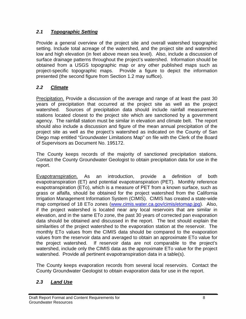
Based on the information obtained of existing and maximum build-out groundwater demand within the watershed, provide tables, which summarize information obtained. Below is an example of a table showing existing water uses (separate tables should be included to document existing and maximum build-out land uses and associated water demand):
Example Table: Project Watershed Existing Water Uses
Land Use Quantity Water Demand Per Unit (afy)
Total Use (afy)
Onsite Single-Family Residential
1 home 0.5 0.5
Offsite Single-Family Residential
25 homes 0.5 12.5
Offsite Second Dwelling Units
4 second dwelling units
0.25 1
Offsite Orange Orchard 3.5 acres 3.8 13.3 Total 26.8
2.5 Geology and Soils Describe the geologic setting of the project site and the project’s watershed including a description of the geologic units and important structural features such as lineaments or faults. Provide a geologic map of the project’s watershed that shows any lineaments, faults, or other important features.
Provide a description of the soil types within the project’s watershed. Descriptions should be based upon the maps and other soil information provided in the San Diego Area Soil Survey (United States Department of Agriculture, 1973). Soil information including the soil name, the moisture holding capacity (in inches), the runoff potential, the estimated maximum runoff percentage, and the approximate area (in acres) within the watershed should be included in a Table(s). Also provide soil types on a figure. Please contact the County Groundwater Geologist for a dataset of soil types within the project’s watershed.
____________________________________________________________________________________ Draft Report Format and Content Requirements for 11 Groundwater Resources
2.6 Hydrogeologic Units Identify and describe all pertinent Hydrogeologic units within the project site and project’s watershed that play an important role in storing and transmitting groundwater. Possible Hydrogeologic units in the County include but are not limited to: moderately-fractured rock (typically found in valley areas), slightly-fractured rock (typically found in upland areas), decomposed granite (or residuum), sedimentary rocks, and alluvium. Include in the discussion the acreage of each unit, specific yield, and well yields expected within each unit. Provide a figure that depicts each of the Hydrogeologic units. It is also helpful to include a generalized Hydrogeologic cross section drawn perpendicular to the groundwater gradient of the project’s watershed. Properly label all Hydrogeologic units, any wells or borings, and include a horizontal and vertical scale on the cross-section. Data sources for the cross section including the logs of test borings and wells should be included in an Appendix. 2.7 Hydrologic Inventory and Groundwater Levels
Inventory of Wells. Provide an inventory of water wells located on the project site and to the extent possible, the project’s watershed. Especially important to note are any high demand wells within the project’s watershed. Include a table with well information documenting the well name, location, well depth, seal depth, production characteristics, and groundwater levels. Also include a figure depicting all wells. Well logs obtained should be included in an Appendix. The County Department of Environmental Health has well logs from well permits dating back to the 1970s. While the well logs are considered confidential, please contact the County Groundwater Geologist to obtain generalized information regarding wells within the project’s watershed such as general depth to water, production characteristics, and any well failures. Hydrologic Features. Provide an inventory of surface water bodies including springs, surface ponds, and reservoirs located on the project site and the project’s watershed. If surface water bodies appear to be augmented with groundwater it should be noted. Groundwater Levels. To the extent possible, groundwater levels should be obtained and documented from the project site and from nearby offsite wells within the project’s watershed to obtain the depth to groundwater. The text should document the general groundwater flow direction, if wells have been surveyed, and the hydraulic gradient at the project site. For some projects, it may be required that groundwater levels be monitored at least quarterly for a year or more to obtain baseline groundwater conditions at the project site.
____________________________________________________________________________________ Draft Report Format and Content Requirements for 12 Groundwater Resources
Water levels from well hydrographs historically monitored by the County of San Diego or other entities within the project’s watershed should be documented and included in a table(s). Please contact the County Groundwater Geologist to obtain groundwater data from wells monitored by the County within the project’s watershed. 2.8 Water Quality Discuss existing groundwater quality to the extent known within the project’s watershed. Information in this section should only document existing water quality information. Water quality data collected as part of the groundwater investigation is discussed separately in Section 4.0. The County has mapped potential nitrate and radioactive elements problem areas, which are included as Figure 5 in the Guidelines for Determining Significance – Groundwater Resources. Please reference the figure, and discuss whether the site lies within a potential problem area for either of these two constituents. It should be noted that this map does not reflect all areas that could have potential impacts, rather it is based on the areas from which samples have been collected.
3.0 GROUNDWATER QUANTITY IMPACT ANALYSIS
Sections 3.1 through 3.3 below contain conditions that, if met, would be considered a significant impact to groundwater resources. These guidelines are based on State CEQA guidelines and address groundwater quantity. In addition, one guideline pertaining to groundwater-dependent habitat is based on CEQA guidelines that address biological resources.
3.1 50% Reduction of Groundwater in Storage (if applicable)
3.1.1 Guidelines for the Determination of Significance
The following condition, if met, would be considered significant impact to groundwater resources: For proposed projects in fractured rock and sedimentary basins, groundwater impacts will be considered significant if a soil moisture balance, or equivalent analysis, conducted using a minimum of 30 years of precipitation data, including drought periods, concludes that at any time groundwater in storage is reduced to a level of 50% or less as a result of groundwater extraction.
Projects that include the entire groundwater basin in the analysis consider cumulative impacts to the entire basin. The project will need to consider basin-wide recharge and groundwater use at maximum build-out of the basin. Projects that include only the project site in the analysis consider direct project effects of the proposed project. In this case, the project will need to consider whether recharge on
____________________________________________________________________________________ Draft Report Format and Content Requirements for 13 Groundwater Resources
the project site is sufficient to provide for the expected water use associated with the proposed project. 3.1.2 Methodology Documentation is needed of procedures, rationale, and calculations for estimates of groundwater recharge from precipitation, the rate of existing and potential groundwater consumption, and the storage capacity of the groundwater basin. Based on this information, this section will also document long-term availability of groundwater at the project site or the project’s watershed depending on the analysis required by the County. Information presented below assumes that the entire watershed is being analyzed. The same basic assumptions apply to a project level analysis. At a minimum, the following information shall be documented and any calculations must be clearly shown for all analysis performed:
3.1.2.1 Groundwater Recharge
Groundwater recharge shall be evaluated for the watershed using the soil moisture balance methodology unless an alternative methodology has been approved in advance by the County Groundwater Geologist. The computer program RECHARG2 or similar and acceptable methodology must be used to calculate groundwater recharge. Include an introduction providing a basic understanding of groundwater recharge and the soil moisture balance methodology. The Thornthwaite Equation should be shown in the text. Discuss where precipitation, evapotranspiration, soil types, and runoff data were obtained and the rationale for using the data. Provide a summary of groundwater recharge calculated using at least 30 years of precipitation data, including drought periods. The following tables should be included in this section:
1. Precipitation data; 2. State CIMIS ETo data and/or reservoir evaporation data; 3. Soil types used in the study including the soil name, the moisture holding
capacity (in inches), the runoff potential, the estimated maximum runoff percentage, and the approximate area (in acres) within the watershed;
4. Runoff data obtained from gaging stations located in the same watershed (if available). In most cases runoff data will not be available and the runoff methodology within Recharg2 should be used;
5. Groundwater recharge calculations.
Artificial recharge from wastewater (i.e., septic systems) return flow has been included in the 0.5 acre-feet per residence per year consumptive use estimate. Wastewater recharge may only be included in residential or any other project’s recharge if the water has been treated at a wastewater treatment facility and adequate documentation can provide conclusive scientific evidence that the water will percolate and recharge the aquifer. If the project site has conditions such as caliche, a relatively deep water table, restrictive soils such as clay or other relatively
____________________________________________________________________________________ Draft Report Format and Content Requirements for 14 Groundwater Resources
impermeable material above the regional water table, it may be difficult to prove any water will actually reach the aquifer.
3.1.2.2 Groundwater Demand
Existing water demand and projected demand at the maximum build-out of the watershed under the County General Plan shall be discussed based on information already similar to information provided in Section 2.0.
3.1.2.3 Groundwater in Storage
Estimates of groundwater storage capacity must be estimated for each hydrogeologic unit at the project site and within the project’s watershed. To estimate groundwater storage for each hydrogeologic unit, estimates of specific yield, the potential saturated thickness, and the extent of the unit are required. Conservative estimates of specific yield should be used in absence of site-specific data. Saturated thickness of residuum or alluvium should be based on site-specific information such as well logs. Estimated storage capacity for each hydrogeologic unit should be summarized in a table. Aerial extent of each hydrogeologic unit should be summarized on a figure. Storage values for basins can be measured by performing aquifer tests on wells and measuring drawdown of water levels in the pumping well and at least one monitoring well. However, it is not always possible to obtain values of storage from well tests. Additionally, calculated storage values for fractured rock aquifers can be inaccurate.
3.1.2.4 Long-Term Groundwater Availability
Using groundwater recharge, groundwater demand, and storage capacity estimated above, long-term groundwater availability must be evaluated to indicate whether groundwater in storage will be reduced to a level of 50% or less as a result of groundwater extraction over at least a 30 year period, including droughts. Also provide a summary of the results including average and minimum storage calculated over the time period evaluated. Also, the maximum sustainable amount of groundwater that could be used without depleting groundwater to 50% or less of the watershed’s potential storage capacity should be documented. A table must be included that shows the calculations of the change of groundwater in storage over time.
3.1.3 Significance of Impacts Prior to Mitigation For projects that include the entire groundwater basin in the analysis, discuss whether groundwater in storage in the project’s basin will be reduced to 50% or less as a result of proposed water use associated with the proposed project. For projects that include only the project site in the analysis, discuss whether groundwater in storage at the project site will be reduced to 50% or less as a result of proposed
____________________________________________________________________________________ Draft Report Format and Content Requirements for 15 Groundwater Resources
water use associated with the proposed project. A summary should be provided from the detailed analysis of groundwater recharge, groundwater demand, groundwater storage, and long-term yield analysis included above.
3.1.4 Mitigation Measures and Design Considerations
Provide brief descriptions of proposed mitigation measures and design considerations. Refer to Section 5.0 of the County Guidelines for Determining Significance for the County’s Typical Mitigation Measures. For each measure, state the impact being mitigated. Mitigation measures for projects with on-going conditions may require additional details, such as a Groundwater Monitoring and Mitigation Plan (GMMP), which should be included as an appendix. 3.1.5 Conclusions
For each significant impact, determine if the proposed mitigation measures have
reduced the significance level to “less than significant” in accordance with stated Significance Guidelines.
3.2 Groundwater Overdraft Conditions (if applicable)
3.2.1 Guidelines for the Determination of Significance
3.2.1.1 Overdraft in Fractured Rock Basins The following condition, if met, would be considered a significant impact to groundwater resources: For fractured rock basins that have been demonstrated to be in an overdraft condition, any additional groundwater use will be considered a significant impact. While there are a number of known potential groundwater problem areas in fractured rock aquifers as documented in Section 1.11 of the County Guidelines for Determining Significance – Groundwater Resources, there are no fractured rock basins that have been officially documented and mapped by the County to be in an overdraft condition. On a case-by-case basis, the County will determine if a project needs to analyze whether or not an overdraft condition is present.
3.2.1.2 Overdraft in Borrego Valley
For Borrego Valley, the following information should be used to evaluate potential cumulative impacts to groundwater resources. Projects will be guided by the following principles:
____________________________________________________________________________________ Draft Report Format and Content Requirements for 16 Groundwater Resources
1. Applicants for projects using groundwater resources in Borrego Valley are encouraged to include with their projects offsetting groundwater use reduction measures, which will make up for the project's proposed groundwater use and result in "no net gain" in the overall rate or amount of extraction of groundwater.
2. For projects where offsetting groundwater use reduction measures are not proposed as part of the project, except as provided in bullets 3 and 4 below, an EIR will generally be required to be prepared, to analyze the significance of cumulative impacts to groundwater resources, to propose mitigation measures, and to consider project alternatives.
3. For projects with previously approved environmental documents, the project must be assessed per the requirements of Section 15162 of the State CEQA Guidelines (summarized at paragraph A.2.b above). If the project proposes to use more groundwater than initially proposed, then offsetting groundwater use reduction measures may be proposed and included in this analysis. If such measures are not included, the Section 15162 analysis may lead to a requirement to prepare a supplemental or subsequent EIR.
4. Proponents of some small projects may be able to demonstrate that potential cumulative impacts to groundwater resources are not significant, because the project's incremental additional groundwater demand is not "cumulatively considerable."
3.2.2 Methodology
If a project lies within a potential groundwater problem area, as documented in Section 1.11 of the Guidelines, or if other evidence of potential overdraft conditions exists, the project shall analyze whether a long-term decline in groundwater levels, dry wells, or other conditions that indicate whether a groundwater overdraft condition is present within the project’s basin. For fractured rock basins, a soil moisture balance (or equivalent analysis) based on existing groundwater demand could also be used to provide a long-term estimation of whether or not more water is being extracted from the basin than is being recharged to the given basin.
3.2.3 Significance of Impacts Prior to Mitigation Discuss the project’s proposed groundwater demand and whether or not it would be considered cumulatively considerable to known overdraft conditions. Currently, the only basin with documented overdraft conditions within the County is Borrego Valley. If a project lies within a potential groundwater problem area where groundwater conditions indicate potential overdraft conditions, a summary should be provided with information such as groundwater levels, dry wells, soil moisture balance analysis, or other information to indicate whether or not there is a groundwater overdraft condition present.
____________________________________________________________________________________ Draft Report Format and Content Requirements for 17 Groundwater Resources
3.2.4 Mitigation Measures and Design Considerations
Provide brief descriptions of proposed mitigation measures and design considerations. Refer to Section 5.0 of the County Guidelines for Determining Significance for the County’s Typical Mitigation Measures. For each measure, state the impact being mitigated. Mitigation measures for projects located within Borrego Valley will need to include a legally enforceable mechanism to achieve a no net gain in water usage as a result of the project. For fractured rock basins, there may be no feasible mitigation unless water can be brought in from another basin or imported water could be utilized.
3.2.5 Conclusions
For each significant impact, determine if the proposed mitigation measures have
reduced the significance level to “less than significant” in accordance with stated Significance Guidelines.
3.3 Well Testing
3.3.1 Guidelines for the Determination of Significance
3.3.1.1 Well Interference in Fractured Rock (if applicable) The following condition, if met, would be considered a significant impact to groundwater resources:
As an initial screening tool, offsite well interference will be considered a significant impact, if after a five year projection of drawdown, the results indicate a decrease in water level of 20 feet or more in the offsite wells. If site-specific data indicates water bearing fractures exist which substantiate an interval of more than 400 feet between the static water level in each offsite well and the deepest major water bearing fracture in the well(s), a decrease in saturated thickness of 5% or more in the offsite wells would be considered a significant impact. If onsite analysis of well interference is required by the County, the guideline for determining significance to onsite wells is identical to the criterion for offsite interference as indicated above.
____________________________________________________________________________________ Draft Report Format and Content Requirements for 18 Groundwater Resources
3.3.1.2 Well Interference in Alluvial or Sedimentary Basins (if applicable) The following condition, if met, would be considered a significant impact to groundwater resources: As an initial screening tool, offsite well interference will be considered a significant impact, if after a five year projection of drawdown, the results indicate a decrease in water level of 5 feet or more in the offsite wells. If site-specific data indicates alluvium or sedimentary rocks exist which substantiate a saturated thickness greater than 100 feet in offsite wells, a decrease in saturated thickness of 5% or more in the offsite wells would be considered a significant impact. If onsite analysis of well interference is required by the County, the threshold for determining significance to onsite wells is identical to the criterion for offsite interference as indicated above. 3.3.1.3 Low Well Yield (if applicable) For residential well tests on lots proposing individual wells, the following conditions, if met, would be considered a significant impact to groundwater resources:
1. Proposed projects requiring groundwater resources for uses associated
with single-family residences require well production during the well test to be no less than 3 gallons per minute (gpm) for each well tested. Proposed projects that cannot meet this requirement will be considered to have a significant impact.
2. Where analysis of a residential well test indicates that greater than 0.5 feet of residual drawdown is projected, the project will be considered to have a significant impact.
3. The analysis of the residential well test must indicate that the amount of drawdown predicted to occur in the well after five years of continual pumping at the rate of projected water demand (a) will not interfere with the continued production of sufficient water to meet the needs of the anticipated residential use(s), and (b) must be less than the saturated depth of water above the pump intake or 100 feet, whichever is less. (The pump intake is assumed to be 50 feet above the bottom of the well). Proposed projects that cannot meet this guideline will be considered to have a significant impact.
____________________________________________________________________________________ Draft Report Format and Content Requirements for 19 Groundwater Resources
3.3.1.4 Groundwater-Dependent Habitat (if applicable)
For projects that have groundwater-dependent habitat on or near the project site, the following condition, if met, would be considered a significant impact to biological resources (as specified in the document County Guidelines for Determining Significance – Biological Resources): The project would draw down the groundwater table to the detriment of groundwater-dependent habitat, typically a drop of 3 feet or more from historical low groundwater levels.
3.3.2 Methodology
This section shall document procedures and analysis of all well tests performed as required by the County. For detailed guidelines on performing residential well tests, please see Attachment A – Guidelines for Performing Residential Well Tests. At a minimum, the following information should be documented and calculations must be clearly shown for all analysis performed: 3.3.2.1 Well Test Description
• A description of each production well location and a figure showing each
production and monitoring well location utilized in the well test; • A description of each well including well depth, well diameter and static water
level(s); • A description of the well test configuration (pump type and size, pump depth,
water level monitoring equipment, location of discharge line, etc.), any pre-test equipment calibration and testing dates/times;
• A description of the pump test duration and recovery times; • A summary of pumping rate (including average rate, minimum, and maximum
rate during test) and the number of well bore volumes removed. All well testing data should be included in an appendix.
3.3.2.2 Well Test Analysis (Show calculations for all analysis performed) • Report total drawdown (including projected drawdown after five years of
sustained pumping) and recovery in tables as illustrated in Attachment A; • Report specific capacity; • Report projected residual drawdown; • Report estimated transmissivity and storativity (if available); • Report offsite and onsite well interference. This should be based on a five year
projection of drawdown using standard hydrologic methods. If multiple wells are being proposed at the project site, the cumulative effect of these wells must be considered when evaluating offsite well interference;
• If required, report whether the project would draw down the groundwater table to the detriment of groundwater-dependent habitat (located on or near the project
____________________________________________________________________________________ Draft Report Format and Content Requirements for 20 Groundwater Resources
site), typically a drop of 3 feet or more from historical low groundwater levels. This should be based on a five year projection of drawdown using standard hydrologic methods.
3.3.3 Significance of Impacts Prior to Mitigation Based on analysis provided above, provide a summary of the following: • For residential well tests, include conclusions that demonstrate whether each
well tested has a significant impact from low well yield; • For offsite and onsite well interference, conclusions must clearly demonstrate
whether potentially significant impacts to well production, on and off property may result from the proposed project’s production;
• For projects required to analyze impacts to groundwater-dependent habitat, include conclusions that demonstrate whether there will be a significant impact to groundwater-dependent habitat;
• For non-residential well tests, provide a brief summary of whether the well test was able to satisfy any County requirements including the County Groundwater Ordinance (Section 67.703.2) and evidence of whether or not the well(s) will be capable of meeting its proposed land use objective(s).
3.3.4 Mitigation Measures and Design Considerations
Provide brief descriptions of proposed mitigation measures and design considerations. For each measure, state the impact being mitigated. Well Interference: Mitigation measures for offsite impacts could include potentially deepening offsite wells with significant impacts, or locating new production wells further away from offsite wells. Low Well Yield: An example mitigation measure for low well yield could be project redesign to eliminate lots that have low well yield or drilling an additional well which can pass the low well yield significance criteria. Groundwater-Dependent Habitat: Mitigation for impacts to groundwater-dependent habitat could include installing a monitoring well between the production well and the groundwater-dependent habitat and setting drawdown thresholds (this is only possible for projects with ongoing conditions, such as an MUP). Another potential mitigation measure for impacts to biological resources would be to locate production wells further away from groundwater-dependent habitat. 3.3.5 Conclusions
For each significant impact, determine if the proposed mitigation measures have
reduced the significance level to “less than significant” in accordance with stated Significance Guidelines.
____________________________________________________________________________________ Draft Report Format and Content Requirements for 21 Groundwater Resources
4.0 WATER QUALITY IMPACT ANALYSIS
4.1 Guidelines for the Determination of Significance
The following condition, if met, would be considered a significant impact:
Groundwater resources for proposed projects requiring a potable water source must not exceed the Primary State or Federal Maximum Contaminant Levels (MCLs) for applicable contaminants. Proposed projects that cannot demonstrate compliance with applicable MCLs will be considered to have a significant impact. In general, projects will be required to sample water supply wells for nitrate, bacteria (fecal and total coliform), and radionuclide activity (change in significance guidelines too). Projects may be required to sample other contaminants of potential concern depending on the geographical location within the County. 4.2 Methodology
For all water quality testing conducted as part of the groundwater investigation, the following information should be included to document procedures and analysis of the data:
4.2.1 Sampling Procedures
• Groundwater Sampling Collection – Include the date(s) groundwater samples
were collected, equipment used to collect samples, the amount of water purged prior to sample collection, and any field parameters (pH, specific conductance, turbidity, and temperature) collected during sampling;
• Analytical Methods – Include analytical method(s) for each constituent and the laboratory that performed the analysis. For most constituents, a laboratory certified by the California Department of Health Services is required;
• Sample Handling and Transportation – Indicate the type of bottles used for each analysis, preservation methods, and sample transportation methods including following proper chain-of-custody procedures [Important: Samples collected by anyone other than a County qualified consultant (or staff/subcontractors under the direct supervision of the qualified consultant) will not be accepted by the County as valid samples].
____________________________________________________________________________________ Draft Report Format and Content Requirements for 22 Groundwater Resources
4.2.2 Sampling Analysis
• Include a summary of groundwater analytical results and compare the results for each constituent with its respective Primary or Secondary State or Federal Maximum Contaminant Levels (MCLs). Depending on the amount of water quality data collected, a table(s) may be helpful to summarize water quality analytical data;
• Indicate whether the samples were analyzed within the laboratory holding times for each constituent.
4.3 Significance of Impacts Prior to Mitigation Significance of water quality impacts to the project site must be discussed based upon water quality sampling performed from onsite wells and in some cases potential for water quality impacts from offsite sources. A summary should be provided from the detailed analysis of water quality included above. The summary must document whether any samples from wells to be used as a potable water source were found to exceed Primary State or Federal MCLs, which would be considered a significant groundwater impact.
4.4 Mitigation Measures and Design Considerations
Provide brief descriptions of proposed mitigation measures and design considerations. Refer to Section 5.0 of the County Guidelines for Determining Significance for the County’s Typical Mitigation Measures. For each measure, state the impact being mitigated. Mitigation measures for water quality could include eliminating portions of the proposed project where water quality impacts exceed MCLs or including a water company or community water system to properly treat significant water quality impacts. 4.5 Conclusions
For each significant impact, determine if the proposed mitigation measures have
reduced the significance level to “less than significant” in accordance with stated Significance Guidelines.
5.0 SUMMARY OF PROJECT IMPACTS AND MITIGATION This section shall provide a brief text summary of project impacts and mitigation. Also, provide conclusions of work conducted to meet the requirements of the San Diego County Groundwater Ordinance or any other groundwater-related regulation associated with the project. This section should also be used to make any non-CEQA conclusions and recommendations regarding groundwater resources.
____________________________________________________________________________________ Draft Report Format and Content Requirements for 23 Groundwater Resources
6.0 REFERENCES This list must provide adequate references to documents cited in the technical study. References that were relied upon and which have a limited circulation must include a location where the public can readily access and review the document. 7.0 LIST OF PREPARERS AND PERSONS AND ORGANIZATIONS
CONTACTED Provide a list of preparers, noting each person included on the County list of approved consultants. Note that the principal author must be on the list or the report will not be accepted. The principal author must sign the report and include their California Professional Geologist number and stamp. TECHNICAL APPENDICES/ATTACHMENTS The Table of Contents shall list each document attached to the report in the order in which they are referenced in the report. As required, the following documents should be included as an appendix in the report: A. Well Testing Data. Include all well testing data collected from each well test
(including clock time, elapsed time, depth to water, drawdown, measured flow rates, and cumulative water pumped);
B. Well Logs. Include copies of all well completion logs (as available) for all wells on the project site and within the project’s watershed;
C. Well Test Plan. Include a copy of the well test plan as required by the County to implement all well tests;
D. Laboratory Analytical Reports. Include copies of all analytical laboratory reports including QA/QC data and chain-of-custodies;
E. Correspondence. Include any pertinent non-County correspondence, which are directly related to the groundwater investigation;
F. Groundwater Monitoring and Mitigation Plan (if required). For projects with on-going conditions or requirements, such as Major Use Permits, a mitigation-monitoring plan may be required. The plan may include such items as monitoring water levels and demand and limiting flow or setting water level thresholds. Specific items to be included in the plan will be determined by the County Groundwater Geologist.
____________________________________________________________________________________ Draft Report Format and Content Requirements for 24 Groundwater Resources
[Attachment A]
Guidelines for Performing Residential Well Tests
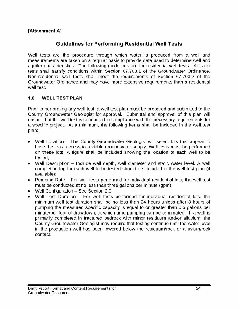
Well tests are the procedure through which water is produced from a well and measurements are taken on a regular basis to provide data used to determine well and aquifer characteristics. The following guidelines are for residential well tests. All such tests shall satisfy conditions within Section 67.703.1 of the Groundwater Ordinance. Non-residential well tests shall meet the requirements of Section 67.703.2 of the Groundwater Ordinance and may have more extensive requirements than a residential well test. 1.0 WELL TEST PLAN Prior to performing any well test, a well test plan must be prepared and submitted to the County Groundwater Geologist for approval. Submittal and approval of this plan will ensure that the well test is conducted in compliance with the necessary requirements for a specific project. At a minimum, the following items shall be included in the well test plan: • Well Location – The County Groundwater Geologist will select lots that appear to
have the least access to a viable groundwater supply. Well tests must be performed on these lots. A figure shall be included showing the location of each well to be tested;
• Well Description – Include well depth, well diameter and static water level. A well completion log for each well to be tested should be included in the well test plan (if available);
• Pumping Rate – For well tests performed for individual residential lots, the well test must be conducted at no less than three gallons per minute (gpm).
• Well Configuration – See Section 2.0; • Well Test Duration – For well tests performed for individual residential lots, the
minimum well test duration shall be no less than 24 hours unless after 8 hours of pumping the measured specific capacity is equal to or greater than 0.5 gallons per minute/per foot of drawdown, at which time pumping can be terminated. If a well is primarily completed in fractured bedrock with minor residuum and/or alluvium, the County Groundwater Geologist may require that testing continue until the water level in the production well has been lowered below the residuum/rock or alluvium/rock contact.
____________________________________________________________________________________ Draft Report Format and Content Requirements for 25 Groundwater Resources
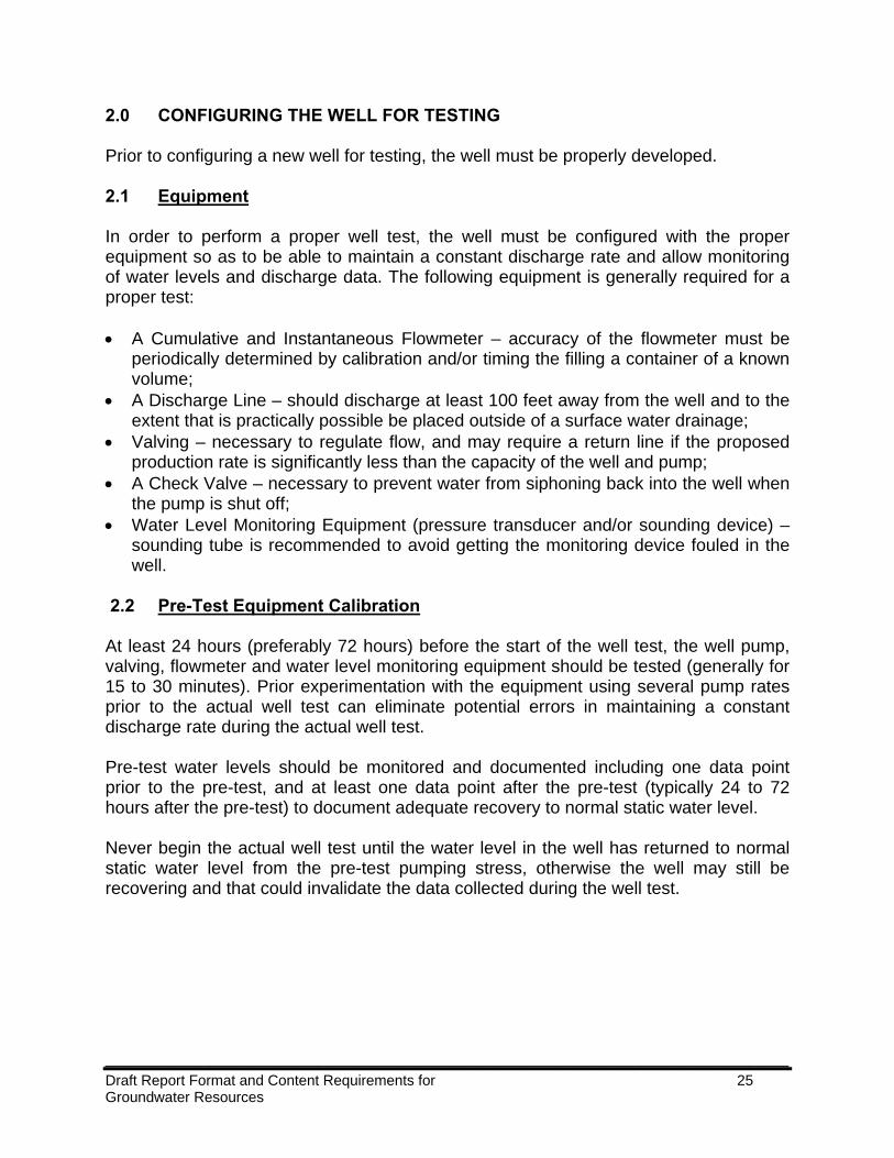
2.0 CONFIGURING THE WELL FOR TESTING Prior to configuring a new well for testing, the well must be properly developed. 2.1 Equipment In order to perform a proper well test, the well must be configured with the proper equipment so as to be able to maintain a constant discharge rate and allow monitoring of water levels and discharge data. The following equipment is generally required for a proper test: • A Cumulative and Instantaneous Flowmeter – accuracy of the flowmeter must be
periodically determined by calibration and/or timing the filling a container of a known volume;
• A Discharge Line – should discharge at least 100 feet away from the well and to the extent that is practically possible be placed outside of a surface water drainage;
• Valving – necessary to regulate flow, and may require a return line if the proposed production rate is significantly less than the capacity of the well and pump;
• A Check Valve – necessary to prevent water from siphoning back into the well when the pump is shut off;
• Water Level Monitoring Equipment (pressure transducer and/or sounding device) – sounding tube is recommended to avoid getting the monitoring device fouled in the well.
2.2 Pre-Test Equipment Calibration At least 24 hours (preferably 72 hours) before the start of the well test, the well pump, valving, flowmeter and water level monitoring equipment should be tested (generally for 15 to 30 minutes). Prior experimentation with the equipment using several pump rates prior to the actual well test can eliminate potential errors in maintaining a constant discharge rate during the actual well test. Pre-test water levels should be monitored and documented including one data point prior to the pre-test, and at least one data point after the pre-test (typically 24 to 72 hours after the pre-test) to document adequate recovery to normal static water level. Never begin the actual well test until the water level in the well has returned to normal static water level from the pre-test pumping stress, otherwise the well may still be recovering and that could invalidate the data collected during the well test.
____________________________________________________________________________________ Draft Report Format and Content Requirements for 26 Groundwater Resources
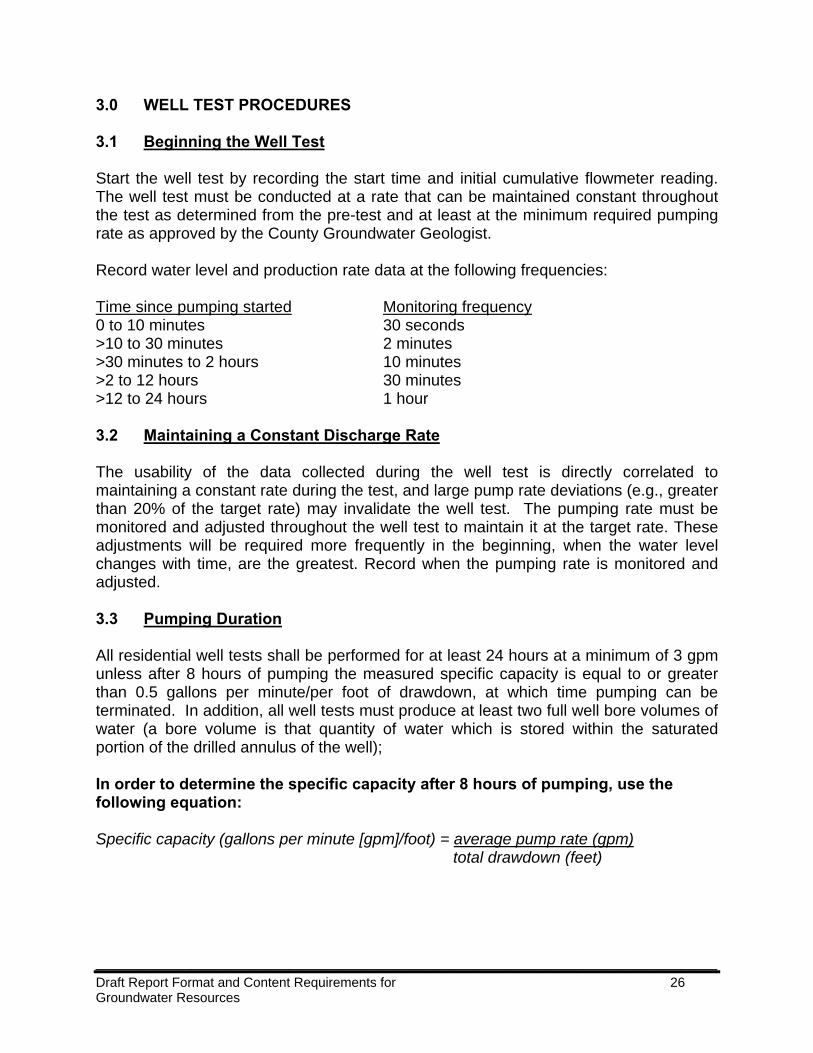
3.0 WELL TEST PROCEDURES 3.1 Beginning the Well Test Start the well test by recording the start time and initial cumulative flowmeter reading. The well test must be conducted at a rate that can be maintained constant throughout the test as determined from the pre-test and at least at the minimum required pumping rate as approved by the County Groundwater Geologist. Record water level and production rate data at the following frequencies: Time since pumping started Monitoring frequency 0 to 10 minutes 30 seconds >10 to 30 minutes 2 minutes >30 minutes to 2 hours 10 minutes >2 to 12 hours 30 minutes >12 to 24 hours 1 hour 3.2 Maintaining a Constant Discharge Rate The usability of the data collected during the well test is directly correlated to maintaining a constant rate during the test, and large pump rate deviations (e.g., greater than 20% of the target rate) may invalidate the well test. The pumping rate must be monitored and adjusted throughout the well test to maintain it at the target rate. These adjustments will be required more frequently in the beginning, when the water level changes with time, are the greatest. Record when the pumping rate is monitored and adjusted. 3.3 Pumping Duration All residential well tests shall be performed for at least 24 hours at a minimum of 3 gpm unless after 8 hours of pumping the measured specific capacity is equal to or greater than 0.5 gallons per minute/per foot of drawdown, at which time pumping can be terminated. In addition, all well tests must produce at least two full well bore volumes of water (a bore volume is that quantity of water which is stored within the saturated portion of the drilled annulus of the well); In order to determine the specific capacity after 8 hours of pumping, use the following equation: Specific capacity (gallons per minute [gpm]/foot) = average pump rate (gpm) total drawdown (feet)
____________________________________________________________________________________ Draft Report Format and Content Requirements for 27 Groundwater Resources
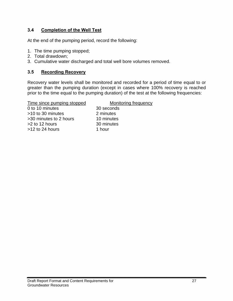
3.4 Completion of the Well Test At the end of the pumping period, record the following: 1. The time pumping stopped; 2. Total drawdown; 3. Cumulative water discharged and total well bore volumes removed. 3.5 Recording Recovery Recovery water levels shall be monitored and recorded for a period of time equal to or greater than the pumping duration (except in cases where 100% recovery is reached prior to the time equal to the pumping duration) of the test at the following frequencies: Time since pumping stopped Monitoring frequency 0 to 10 minutes 30 seconds >10 to 30 minutes 2 minutes >30 minutes to 2 hours 10 minutes >2 to 12 hours 30 minutes >12 to 24 hours 1 hour
____________________________________________________________________________________ Draft Report Format and Content Requirements for 28 Groundwater Resources
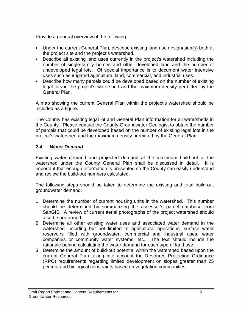
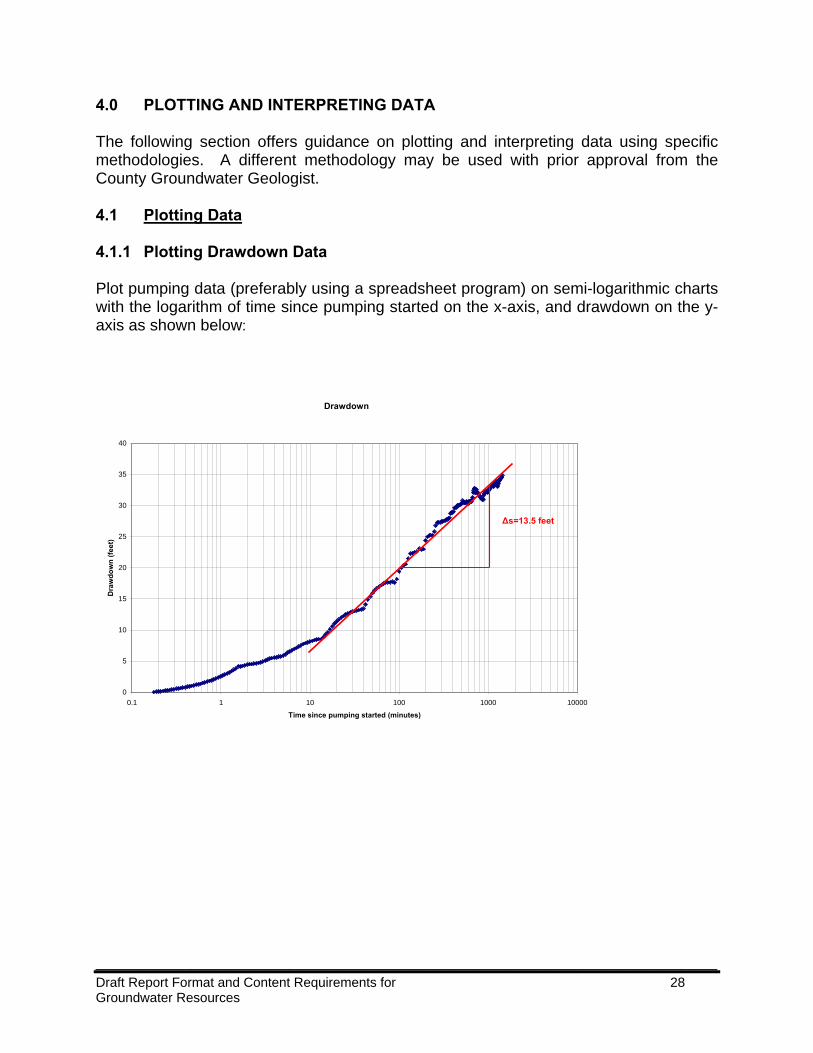
4.0 PLOTTING AND INTERPRETING DATA The following section offers guidance on plotting and interpreting data using specific methodologies. A different methodology may be used with prior approval from the County Groundwater Geologist. 4.1 Plotting Data 4.1.1 Plotting Drawdown Data Plot pumping data (preferably using a spreadsheet program) on semi-logarithmic charts with the logarithm of time since pumping started on the x-axis, and drawdown on the y-axis as shown below:
Drawdown
0
5
10
15
20
25
30
35
40
0.1 1 10 100 1000 10000
Time since pumping started (minutes)
Dra
wdo
wn
(feet
)
Δs=13.5 feet
____________________________________________________________________________________ Draft Report Format and Content Requirements for 29 Groundwater Resources
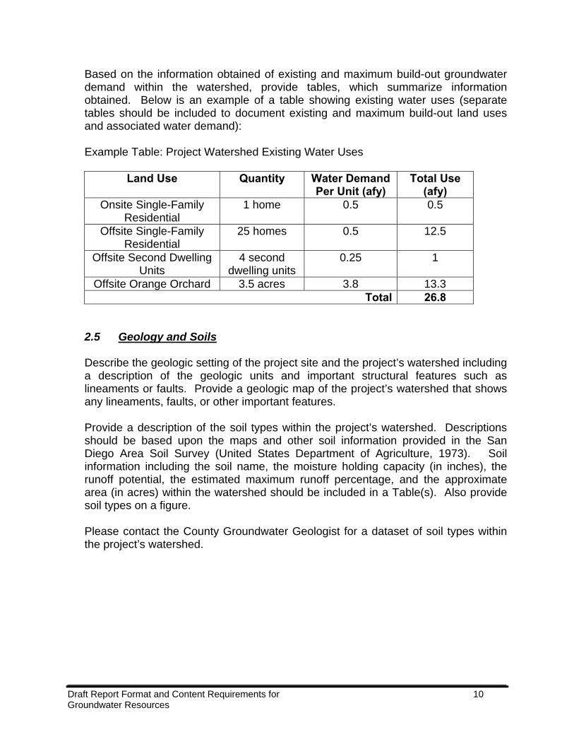
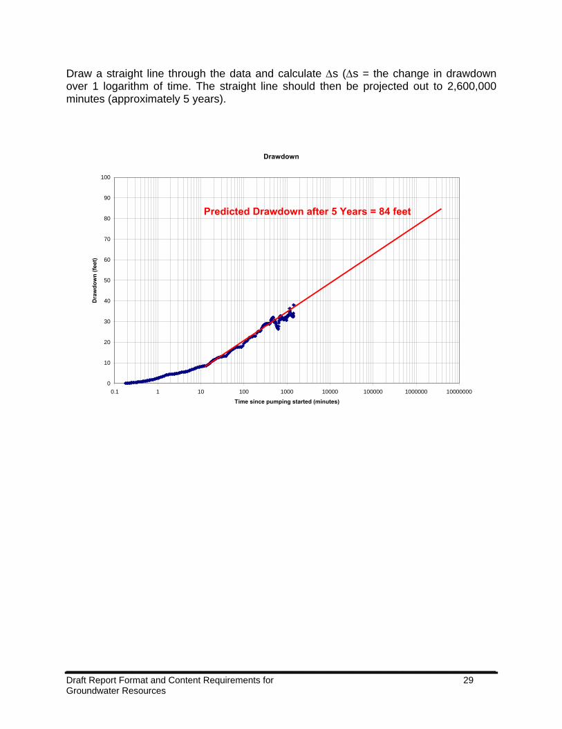
Draw a straight line through the data and calculate Δs (Δs = the change in drawdown over 1 logarithm of time. The straight line should then be projected out to 2,600,000 minutes (approximately 5 years).
Drawdown
0
10
20
30
40
50
60
70
80
90
100
0.1 1 10 100 1000 10000 100000 1000000 10000000
Time since pumping started (minutes)
Dra
wdo
wn
(feet
)
Predicted Drawdown after 5 Years = 84 feet
____________________________________________________________________________________ Draft Report Format and Content Requirements for 30 Groundwater Resources
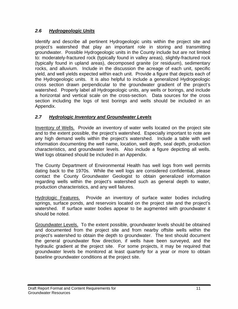
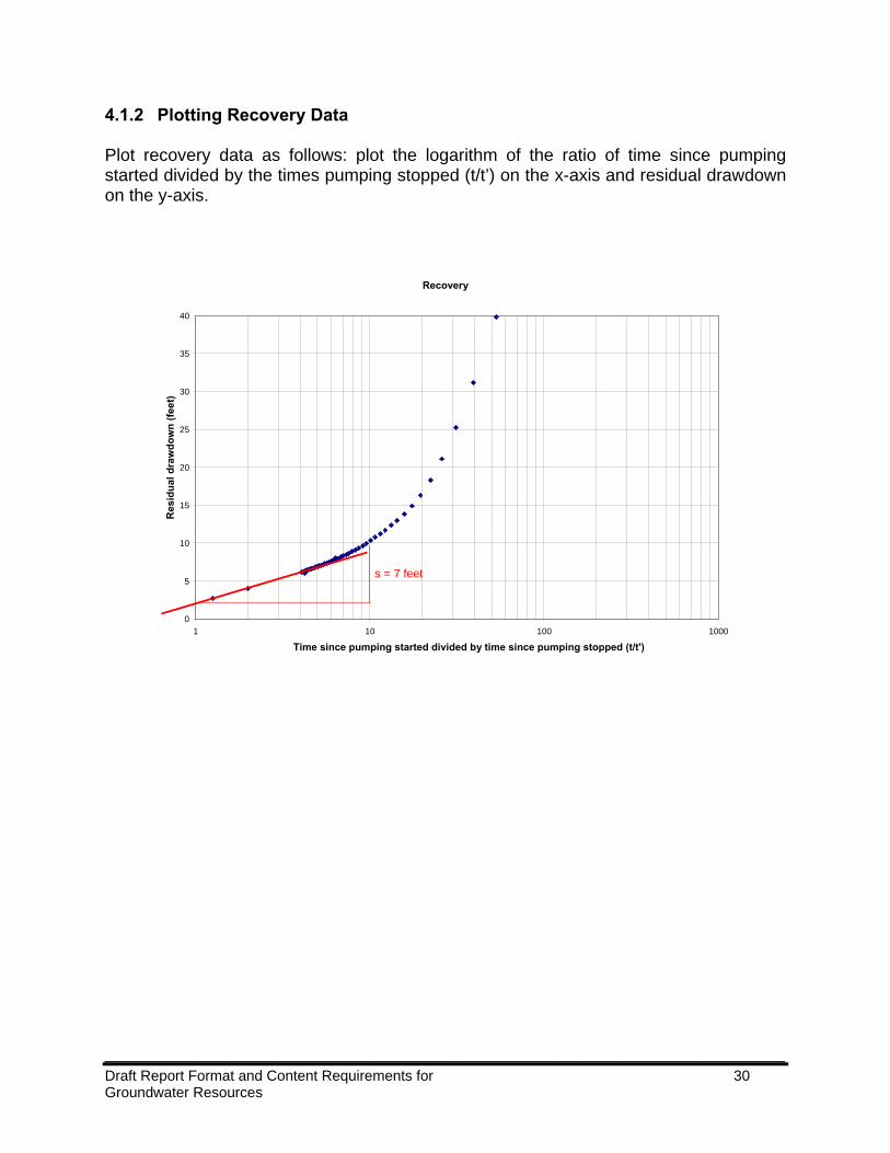
4.1.2 Plotting Recovery Data Plot recovery data as follows: plot the logarithm of the ratio of time since pumping started divided by the times pumping stopped (t/t’) on the x-axis and residual drawdown on the y-axis.
Recovery
0
5
10
15
20
25
30
35
40
1 10 100 1000
Time since pumping started divided by time since pumping stopped (t/t')
Res
idua
l dra
wdo
wn
(feet
)
s = 7 feet
____________________________________________________________________________________ Draft Report Format and Content Requirements for 31 Groundwater Resources
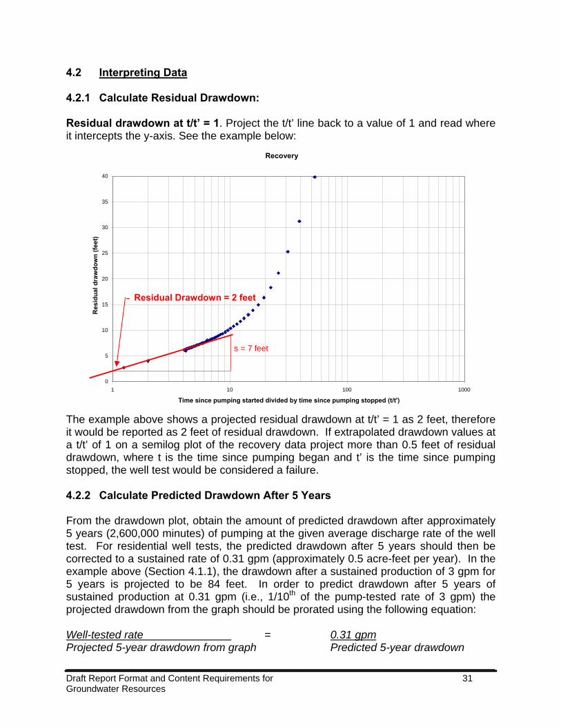
4.2 Interpreting Data 4.2.1 Calculate Residual Drawdown: Residual drawdown at t/t’ = 1. Project the t/t’ line back to a value of 1 and read where it intercepts the y-axis. See the example below:
The example above shows a projected residual drawdown at t/t’ = 1 as 2 feet, therefore it would be reported as 2 feet of residual drawdown. If extrapolated drawdown values at a t/t’ of 1 on a semilog plot of the recovery data project more than 0.5 feet of residual drawdown, where t is the time since pumping began and t’ is the time since pumping stopped, the well test would be considered a failure. 4.2.2 Calculate Predicted Drawdown After 5 Years From the drawdown plot, obtain the amount of predicted drawdown after approximately 5 years (2,600,000 minutes) of pumping at the given average discharge rate of the well test. For residential well tests, the predicted drawdown after 5 years should then be corrected to a sustained rate of 0.31 gpm (approximately 0.5 acre-feet per year). In the example above (Section 4.1.1), the drawdown after a sustained production of 3 gpm for 5 years is projected to be 84 feet. In order to predict drawdown after 5 years of sustained production at 0.31 gpm (i.e., 1/10th of the pump-tested rate of 3 gpm) the projected drawdown from the graph should be prorated using the following equation: Well-tested rate = 0.31 gpm Projected 5-year drawdown from graph Predicted 5-year drawdown
Recovery
0
5
10
15
20
25
30
35
40
1 10 100 1000
Time since pumping started divided by time since pumping stopped (t/t')
Res
idua
l dra
wdo
wn
(feet
)
s = 7 feet
Residual Drawdown = 2 feet
____________________________________________________________________________________ Draft Report Format and Content Requirements for 32 Groundwater Resources
In our example the calculation would be as follows: 3 gpm = 0.31 gpm 84 feet s After cross multiplying and dividing, we get: s = 8.4 feet This is the predicted drawdown after sustained pumping from 5 years at 0.31 gpm. Predicted drawdown after five years must be less than the saturated depth of water above the pump intake or 100 feet, whichever is less (the pump intake is assumed to be 50 feet above the bottom of the well). If the predicted drawdown exceeds this depth, the well test would be considered a failure. This method is only useful when the drawdown data is reasonably linear for the majority of the plot. If the plot indicates a constant-head boundary, no-flow boundary, dewatered alluvium, dewatered residuum, a stranded fracture, or single fracture, another interpretation should be used and approved in advance by the County Groundwater Geologist. 4.2.3 Calculate Transmissivity Calculate transmissivity using the Cooper-Jacobs approximation1 to the Theis equation, which states: T= 2.3 x Q 4 x π x Δs Where: T = Transmissivity (feet²/day) Q = average pumping rate (feet³/day [multiply gpm by 193]) π = 3.14 Δs= the change in drawdown over 1 logarithm of time [or t/t’ for recovery data] 1Cooper, H.H., Jr. and C.E. Jacobs. 1946. A Generalized Graphical Method for Evaluating Formation Constraints and Summarizing Well Field History. Transactions, American Geophysical Union 27:526-34.