Embed Size (px)
Citation preview

Coupled Adjoint Optimisation for a
Flexible Wing with Fluid-Structure
Interaction
A. Stannard, PhD studentN. Qin, Academic SupervisorDepartment of Mechanical EngineeringUniversity of Sheffield
Funded by EPSRC DTG and Airbus

29/11/2019 © The University of Sheffield
2
Motivation: To enable coupled adjoint optimization for fluid-structure interaction simulations of aircraft
• Minimize optimization run time
• Unconstrained gradient-based algorithms
• Adjoint-based gradients for efficiency
• Trim in the loop
• Direct mesh deformation methods
• High-fidelity modelling
• RANS-based CFD
• FEM-based CSM

29/11/2019 © The University of Sheffield
3
Use of FlowSimulator for aeroelastic coupling• Parallel environment for solving
multi-physics simulations
• The Data Manager holds data in memory to reduce time consuming I/O
• High fidelity CFD and CSM solvers TAU and Nastran

FSI in FlowSimulator• Sequentially solve the Fluid
and Structural problems
• Interpolate the forces between the TAU and Nastran
• Inner loop for FSI convergence and outer loop for Trim convergence
4
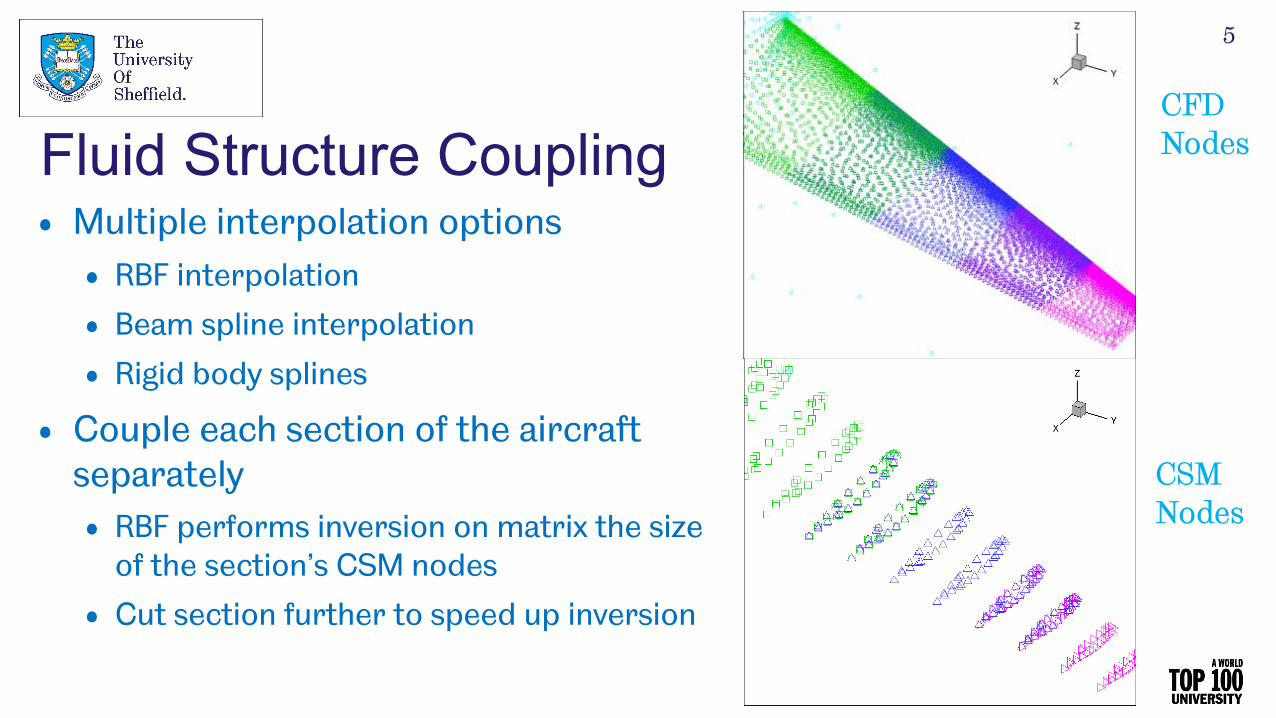
Fluid Structure Coupling• Multiple interpolation options
• RBF interpolation
• Beam spline interpolation
• Rigid body splines
• Couple each section of the aircraft separately• RBF performs inversion on matrix the size
of the section’s CSM nodes
• Cut section further to speed up inversion
CFD Nodes
CSM Nodes
5

Create Control Surfaces• Define arbitrary control surface
locations with cutting method
• Control surface deflections on CSM mesh nodes added to CSM displacements• These are interpolated to the CFD
surface
• Ensures smooth continuous surface
• Potential to create active camber trailing edge device
6

Two Strategies for Mesh Deformation• RBF Mesh Deformation
• Handles large deformations well
• Fast: Calculates mesh sensitivity on the fly
• Uses subset of surface points: Sacrificing
surface resolution
• Delaunay Mesh Deformation
• Very fast: Explicitly stores mesh sensitivity
• Uses all surface points
• Can’t handle very large deformations
7

Optimisation overview• Optimisation algorithm
• Minimise !"• Gradient-based
• Unconstrained BFGS method
• Shape Parameterisation
• Surrogate CATIA v5 model
8
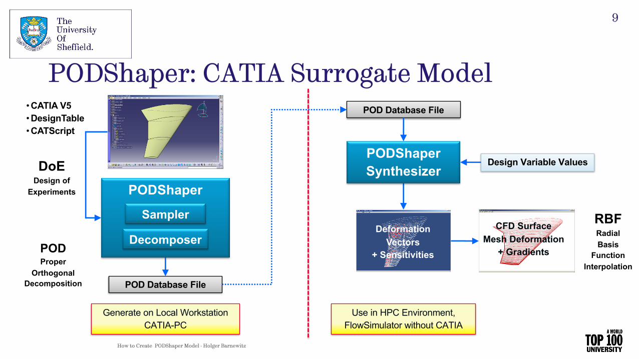
PODShaper: CATIA Surrogate Model
How to Create PODShaper Model - Holger Barnewitz
PODShaper
Sampler
Decomposer
• CATIA V5• DesignTable• CATScript
POD Database File
PODShaperSynthesizer
DeformationVectors
+ Sensitivities
CFD SurfaceMesh Deformation
+ Gradients
Generate on Local WorkstationCATIA-PC
Use in HPC Environment,FlowSimulator without CATIA
DoEDesign of
Experiments
POD Database File
PODProper
OrthogonalDecomposition
Design Variable Values
RBFRadialBasis
FunctionInterpolation
9
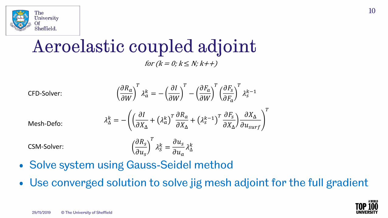
Aeroelastic coupled adjoint
29/11/2019 © The University of Sheffield
10
for(k=0;k≤ N;k++)
./0
.12304 = − .6
.12− .70
.12 .78.70
23849:
3∆4 = − .6.<=
+ 3042 ./0.<=
+ 3849:2 .78.<=
.<=.>8?@A
2
./8
.>823B4 =
.>8
.>03∆4
CFD-Solver:
CSM-Solver:
Mesh-Defo:
• Solve system using Gauss-Seidel method
• Use converged solution to solve jig mesh adjoint for the full gradient

Trim Correction!"#$!% = '()#$
(% *,,+ .#$
!/!% + 0#$
!1!% = 0
!"3!% = '()3
(% *,,+ .3
!/!% + 03
!1!% = 0
!"4!% = '()4
(% *,,+ .4
!/!% + 04
!1!%
29/11/2019 © The University of Sheffield
11
• All values are known except 5*54 and 5,54
• These are found by solving a simultaneous equation

• Successful validation for both Delaunay and RBF mesh deformation approaches at low Mach numbers
Coupled Adjoint Validation
12

• The coupled adjoint suffers convergence problems with the RBF approach at higher Mach numbers
• Use RBF in FSI simulation and use Delaunay in coupled adjoint
Non-Consistent mesh deformation
13

Test Case Description: LANN-WingAircraft configuration
• Wing Only
Objective
• Minimise Drag
Optimization point
• Cruise Mach: 0.73
• Cruise Cl: 0.4
Parameterization
• 8 PODShaper Parameters
• 2 Twist parameters
• 3 separate camber locations
14

• Optimiser performed well with steepest descent
• BFGS moved with step sizes that were too small (despite scaling the gradient)
Optimisation History
15

Optimisation Results: !" Contours
Original Pressure Contours Optimised Pressure Contours
16

Optimisation Results: Shape Changes
17

Summary• Presented trimmed aeroelastic gradient-based optimization
process
• Adjoint-based gradients
• High-fidelity CFD & CSM coupling
• Efficient in-memory and HPC-based Workflow
• Surrogate CAD model parameterization
• Demonstration on a simple wing test case
Future Work• Trim optimisation on XRF1
• Use control surface interpolation to represent a morphing
wing mechanism
• Run coupled adjoint trim optimization on full aircraft
configuration with morphing wing parameters
18

Dr J. Pattinson, PhDFor showing me the ropes with FlowSimulator and consistent help
M. CrossFor help in moving the project forward
A. MerleFor helping to debug some tricky problems
Acknowledgments
19

20


![A parallel aerostructural optimization framework for ...gkennedy.gatech.edu/wp-content/uploads/2014/12/... · Kenway et al.[2014] developed a more scalable coupled adjoint for high-fidelity](https://img.pdfslide.net/doc/110x75/60861d0cf4cbbc490c47d545/a-parallel-aerostructural-optimization-framework-for-kenway-et-al2014-developed.jpg)