Embed Size (px)
Citation preview

ICVE2015, Shanghai (China) 18-20 September 2015 1
COUPLED VIBRATION ANALYSIS OF SHIP ENGINE-BOTTOM USING COMPONENT MODE SYNTHESIS
Wen Qin, Deyu Wang
The State Key Laboratory of Ocean Engineering, Shanghai Jiaotong University, Dongchuan Road
800,200240 Shanghai, China
e-mail: [email protected]
The objective in this paper is to present an approach of coupled vibration analyzing of ship
engine-double bottom system using the component mode synthesis (CMS) method. In tradi-
tional modal analysis of this coupled system, simplifying the engine as concentrated masses
can’t reflect the effects of engine vibration, and a complete 3D finite element model drasti-
cally increases computational cost. Thus, the CMS method is applied to deal with these
problems in this paper. Modal synthesis of the engine and the double bottom was accom-
plished by MATLAB, and the reduced-order coupled system matrices could be obtained.
Example solutions illustrated that this approach effectively reduced the cost of computation
and retained the vibration information of the coupled system. Also examples demonstrated
the advantages of this approach in cases where substructures were modified, since only the
mode information of modified substructure need to be computed.
1. Introduction
Severe ship vibration can cause ship structure failures, machinery malfunction and physically
sickness of crew. Excitation by the engine is one of the major reasons. The unbalanced force and
moment generated as the engine runs vibrates the engine mount, then propagates to local vibration
of the ship bottom, cabin bulkhead, and even the superstructure.
The relationship between ship hull vibration and the engine mount vibration is as follows: (1)
engine mount H-type, X-type and x-type vibration have little effects on the ship hull, but local reso-
nance can be harmful to the navigability of the ship; (2) transverse vibration of ship hull, which
contains torsion vibration, is easily to induce transverse vibration of the engine mount[1]. In fact, it’s
fully coupled between the engine, engine mount and the double bottom, comprehensive analysis is
needed to reach a reasonable accurate solution.
The most commonly applied three modelling methods in dynamic analysis of ship structures are:
3D solid finite element engine mode, 2D shell and 0D point finite element engine model and 0D
point with MPC element engine model[2-4]. Among these, 3D modelling costs heavy workload and
large amount of computation. 0D point with MPC element modelling (the MPC method) gives
mode shapes very different from 3D model. Contrasted to the two method above, 2D model is a
compromising method.
In order to efficiently and accurately analyse the coupled vibration of ship engine-bottom system,
this paper applied the Craig-Bampton CMS method in the dynamic analyse process in MATLAB.
Extensive research on the CMS method has been done, most of which aim at controlling error and
The 7th International Congress on Vibration Engineering
ICVE2015, Shanghai (China) 18-20 September 2015 2
improving accuracy[5-7]. However not all of the results can be applied to solving complex engineer-
ing problems, so emphasis in this paper is placed on the application of this method in ship engineer-
ing. Some illustrative example solutions of a ship engine-bottom are given to show the applicability
and advantage of this approach.
2. The Craig-Bampton method
The Component Mode Synthesis (CMS) method firstly divides the structure into several sub-
structures, and separately calculates the eigenvalues and mode shapes. Then assembles the integrat-
ed eigen-equation according to compatibility conditions of the interfaces. Finally solves this equa-
tion and transforms the mode shapes from modal coordinate to physical coordinate. The method
optimizes the workflow naturally by using modal coordinate instead of physical coordinate during
the computation.
The CMS methods are divided into three categories on the basis of the interface constraint condi-
tions: the fixed-interface CMS, the free-interface CMS and the mixed-interface CMS[8]. Considered
that steel structures are linear systems and the connection between the engine mount and the bottom
is relatively strong, we focus on the Craig-Bampton CMS, which is the easiest to perform.
Consider the free vibration equation of an undamped structure
0M u K u (1)
where M and K are the symmetric mass and stiffness matrices of the complete finite element
system of n equations, and u is the array of node displacement. We partition the dynamic equi-
librium equations above as follow
0ii ij i ii ij i
ji jj j ji jj j j
M M u K K u
M M u K K u f
(2)
where the subscript i refers to the degree of the freedom of interior nodes and j refers to the de-
gree of the freedom of boundary nodes, jf refers to the interfacial force produced when substruc-
tures were divided. Then the following transformation is performed
Φ
0 I
i kik ij
j c
u pu p
u p
(3)
where I is the identity matrix, ik is the normal modes matrix corresponding to the smallest k
eigenvalues with all boundary degrees of freedom fixed, usually k n , [Φ ]ij is the constraint
modes matrix given as
-1
-ij ii ijK K (4)
and p represents the modal coordinates, the subscript k refers to the normal modes and c refers
to the constraint modes.
Then the first time transformation of coordinates is performed as
1
TK K (5)
1
TM M (6)
Supposing that there are substructures a and b , the freedom of degree of nodes in the interface
should satisfy the compatibility condition of displacement
a b
c cp p (7)
the second coordinate transformation matrix can be derived from

The 7th International Congress on Vibration Engineering
ICVE2015, Shanghai (China) 18-20 September 2015 3
I 0 0
0 I 0
0 0 I
0 I 0
a
ak
kak ac
cbc bk
kb
c
pp
p pp p T q
p pp
p
(8)
where T is the second transformation matrix, q is the general displacement in modal coordi-
nate. Then perform the second coordinate transformation
2 1
2 1
T
T
K T K T
M T M T
(9)
After that the reduced eigenvalue problem is solved
2 2[ ] [ ]K X M X (10)
The eigenvalue approximations are given in and the eigenvectors in modal coordinate are
listed in [ ]X . To get the eigenvectors in physical coordinate, the following reverse transformation
must be performed
[ ] [ ]T X (11)
The eigenvector approximations are given in [ ] .
3. Modal analysis of engine-bottom structure
The finite element model shown in Figure 1 (a) is divided into two substructures. Substructure a
is modeled using 9433 elements and 3534 interior nodes, substructure b is modeled using 825 ele-
ments and 661 interior nodes, and there are 46 boundary nodes in the interface.
(a) Model 1,engine-bottom model
(b) Model 2,MPC model
Figure 1. Finite element model of engine-bottom.
3.1 The program flow of the Craig-Bampton Method
The program flow of the Craig-Bampton method is shown in Figure 2. The user can define the
mass and stiffness matrixes of the substructures, interfacial nodes information, modes that are in-
tended to be the Ritz bases and the desired m smallest approximated eigenvalue of the structure.
It can be concluded that the order of the reduced eigen-equation is decided by i and j . For ex-
ample, the order of the reduced eigen-equation is
1r = 6a bk k j (12)
while in the conventional mode analysis of the engine-bottom structure the order of the equation is
2r =6 )a bi i j ( (13)

The 7th International Congress on Vibration Engineering
ICVE2015, Shanghai (China) 18-20 September 2015 4
Usually the number of nodes in finite element model of ship structure is much larger than the
number of model Ritz bases when performing the CMS method, i.e. i k , thus the analysing effi-
ciency can be apparently improved by applying the CMS method in large complex structures.
Substructures;
Interfacial nodes information;
Normal modes desired to be Ritz
base;
Normal modes;
Constraint modes;
RE
DU
CU
TIO
NFirst transformation matrix
Interfacial nodes displacement
accordance;
Second transformation matrix
SO
LU
TIO
NSolve the eigen-equation
Transformation to physical
coordinate
Approximated frequencies;
Approximated mode of vibration
OU
TP
UT
INP
UT
Figure 2. MATLAB flow of the Craig-Bampton method.
3.2 Solution of engine-bottom structure
In this section solutions are given to show the advantages of the CMS method in effectiveness
and accuracy. These solutions are mode analysis of the entire finite element model performed in
NASTRAN, the CMS method and contrastively the MPC method. In the CMS process, modes cor-
responding to the smallest 20 eigenvalues of each substructure are retained as Ritz bases.
(a) 1st mode shape, engine H type
(b) 2nd mode shape, entire vertical
The 7th International Congress on Vibration Engineering
ICVE2015, Shanghai (China) 18-20 September 2015 5
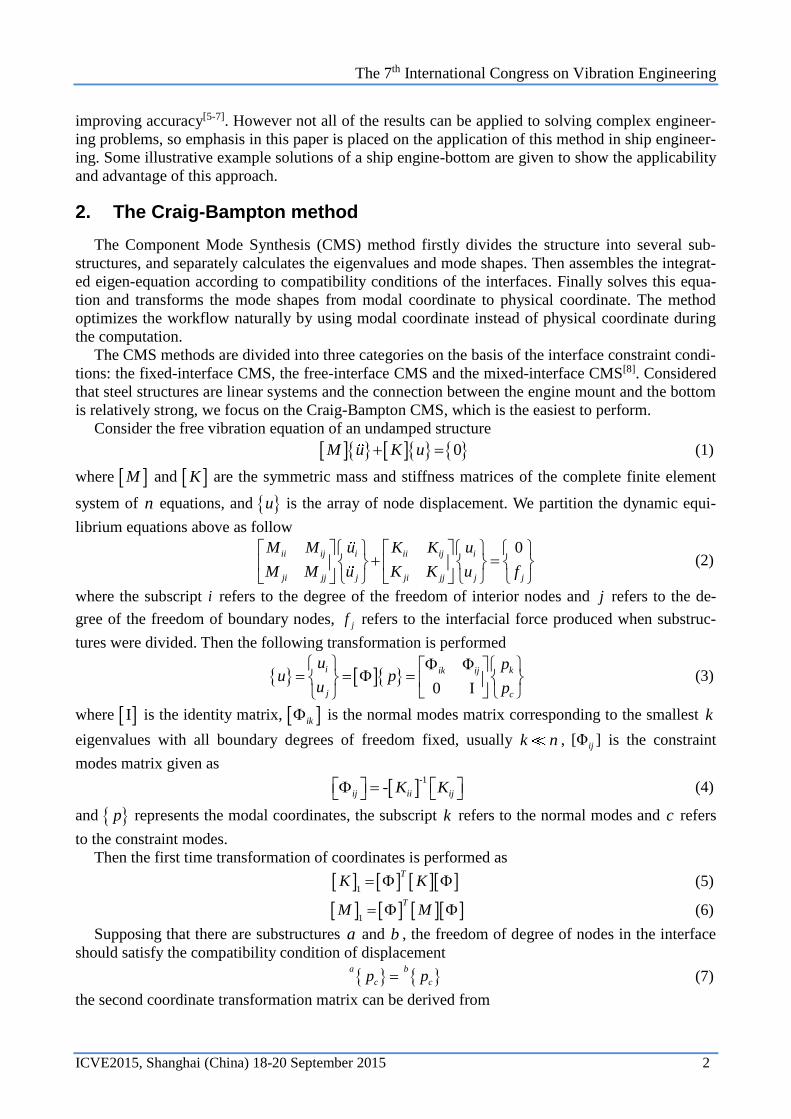
(c) 3rd mode shape, engine L type
(d) 4th mode shape, entire vertical
(e) 5th mode shape, engine X type
Figure 3. Comparison of mode shapes corresponding to the smallest 5 eigenvalues. Left: integrated mode
analysis by NASTRAN; Right: using the CMS method.
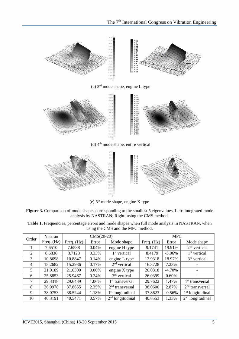
Table 1. Frequencies, percentage errors and mode shapes when full mode analysis in NASTRAN, when
using the CMS and the MPC method.
Order Nastran
Freq. (Hz)
CMS(20-20) MPC
Freq. (Hz) Error Mode shape Freq. (Hz) Error Mode shape
1 7.6510 7.6538 0.04% engine H type 9.1741 19.91% 2nd vertical
2 8.6836 8.7123 0.33% 1st vertical 8.4179 -3.06% 1st vertical
3 10.8698 10.8847 0.14% engine L type 12.9318 18.97% 3rd vertical
4 15.2682 15.2936 0.17% 2nd vertical 16.3728 7.23% -
5 21.0189 21.0309 0.06% engine X type 20.0318 -4.70% -
6 25.8853 25.9467 0.24% 3rd vertical 26.0399 0.60% -
7 29.3318 29.6439 1.06% 1st transversal 29.7622 1.47% 1st transversal
8 36.9978 37.8655 2.35% 2nd transversal 38.0600 2.87% 2nd transversal
9 38.0753 38.5244 1.18% 1st longitudinal 37.8623 -0.56% 1st longitudinal
10 40.3191 40.5471 0.57% 2nd longitudinal 40.8553 1.33% 2nd longitudinal

The 7th International Congress on Vibration Engineering
ICVE2015, Shanghai (China) 18-20 September 2015 6
As shown in Table 1 and Figure 3, the CMS method calculates the approximation of eigenvalues
accurately as well as the mode shapes. The MPC method ignores the deformation of the engine
mount since the interface between the bottom and the engine is rigid, as a result, the mode shapes is
much different from the actual ones.
3.3 Principles of choosing the retained normal modes
As is discussed in Section 2, the Craig-Bampton method improves the work flow naturally by us-
ing modal coordinates. By using numbered normal modes of substructures as Ritz bases instead of
physical coordinates of nodes, the order of the eigen-equation is significantly reduced. After that,
it’s natural to consider how to choose the normal modes to be Ritz bases. In this section different
normal modes are retained in the CMS process and then the smallest 50 frequencies of the structure
are compared to illustrate the principles of choosing the retained normal modes.
In Figure 4, M and N of CMS ( -M N ) refer to the first M modes of substructure a and the
first N modes of substructure b . It shows that the CMS method calculates the lower order modes
of the structure more accurately than higher modes. And also, results of CMS(20-20) is even more
accurate than that of CMS(10-10), which means that the more normal modes are retained, the more
accurate the results will be. Besides, comparing the results of CMS(10-10), CMS(10-30) and
CMS(30-10), it’s obvious that retaining more normal modes of substructure a affects the synthesis
result more.
Conclusion can be made as follow: substructure a contributes more in vibration of the system.
In practice, the stiffness of the engine is larger than the bottom, so that lower frequencies will in-
duce more natural modes of the bottom. When applying CMS method in actual ship structures, con-
sidering from the cost of computing, retaining more normal modes of the relatively tender substruc-
tures can improve the efficiency better.
Figure 4. Percentage errors in frequencies using the CMS with different mode bases and the MPC method.
3.4 Application in structural modification
When ship structure needs to be modified or equipment installation location needs to be changed
in ship design process, dynamic analysis of the modified structure must be recalculated. In this case,
calculation of substructures unmodified is just repeated, which is a waste of computing cost. Under
The 7th International Congress on Vibration Engineering
ICVE2015, Shanghai (China) 18-20 September 2015 7
this premise, the method can be applied to model reduction in designation and dynamic analysis of
large and complex structures, and also to improving efficiency by recalculating exclusively part of
the substructures[5].
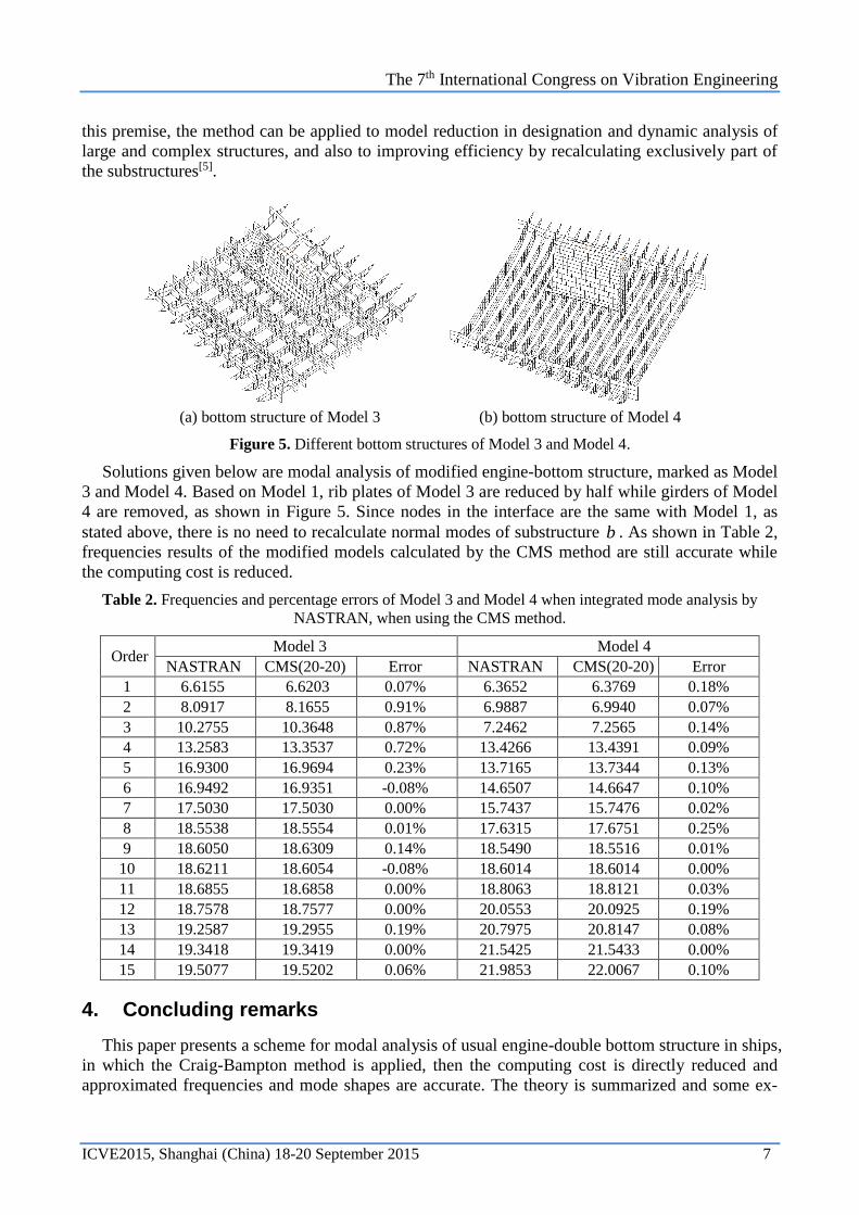
(a) bottom structure of Model 3
(b) bottom structure of Model 4
Figure 5. Different bottom structures of Model 3 and Model 4.
Solutions given below are modal analysis of modified engine-bottom structure, marked as Model
3 and Model 4. Based on Model 1, rib plates of Model 3 are reduced by half while girders of Model
4 are removed, as shown in Figure 5. Since nodes in the interface are the same with Model 1, as
stated above, there is no need to recalculate normal modes of substructure b . As shown in Table 2,
frequencies results of the modified models calculated by the CMS method are still accurate while
the computing cost is reduced.
Table 2. Frequencies and percentage errors of Model 3 and Model 4 when integrated mode analysis by
NASTRAN, when using the CMS method.
Order Model 3 Model 4
NASTRAN CMS(20-20) Error NASTRAN CMS(20-20) Error
1 6.6155 6.6203 0.07% 6.3652 6.3769 0.18%
2 8.0917 8.1655 0.91% 6.9887 6.9940 0.07%
3 10.2755 10.3648 0.87% 7.2462 7.2565 0.14%
4 13.2583 13.3537 0.72% 13.4266 13.4391 0.09%
5 16.9300 16.9694 0.23% 13.7165 13.7344 0.13%
6 16.9492 16.9351 -0.08% 14.6507 14.6647 0.10%
7 17.5030 17.5030 0.00% 15.7437 15.7476 0.02%
8 18.5538 18.5554 0.01% 17.6315 17.6751 0.25%
9 18.6050 18.6309 0.14% 18.5490 18.5516 0.01%
10 18.6211 18.6054 -0.08% 18.6014 18.6014 0.00%
11 18.6855 18.6858 0.00% 18.8063 18.8121 0.03%
12 18.7578 18.7577 0.00% 20.0553 20.0925 0.19%
13 19.2587 19.2955 0.19% 20.7975 20.8147 0.08%
14 19.3418 19.3419 0.00% 21.5425 21.5433 0.00%
15 19.5077 19.5202 0.06% 21.9853 22.0067 0.10%
4. Concluding remarks
This paper presents a scheme for modal analysis of usual engine-double bottom structure in ships,
in which the Craig-Bampton method is applied, then the computing cost is directly reduced and
approximated frequencies and mode shapes are accurate. The theory is summarized and some ex-

The 7th International Congress on Vibration Engineering
ICVE2015, Shanghai (China) 18-20 September 2015 8
ample solutions are given to illustrate the use of this solution scheme. Characteristics of the scheme
are:
(1) Compared with modal analysis of the entire structure with NASTRAN, the scheme can pro-
vide good accuracy in practical engineering as well as reduce the calculation cost.
(2) Compared with conventional MPC method, the scheme considers the effect of engine mount
vibration on ship bottom adequately, so that mode shapes are coincided with actual ones.
(3) Retaining more normal modes of relatively tender substructures can efficiently improves the
accuracy.
(4) It’s advantageous to apply the scheme in structural modification problems.
There are plenty researches on improving the accuracy of CMS method, however, those re-
searches are not fully applied in practical ship design or structural examination, thus this paper pays
more attention on the application of the method. Further efforts to possibly take advantage of the
CMS method can be pursued such as combining with other algorithm such as uncertainty analysis[9]
or applying this scheme in structural dynamic optimization[10].
REFERENCES
1 China Classification Society, Guidance on Ship Vibration Control, (2000).
2 Zou C. P, Chen D. S, Hua H. X, Modal synthesis method of structural vibration analysis of
ship, Journal of Shanghai Jiao Tong University-Chinese edition, 37(8): 1213-1218, (2003).
3 Li W. H, Study of natural and forced vibration analysis on very large container vessels,
MA.Eng. Thesis, Dalian University of Technology, (2012).
4 Wang C. J, Study of dynamic characteristic optimum design, MA.Eng. Thesis, Shanghai Jiao
Tong University, (2011).
5 Zheng G. T, Liu M. H, Progress in component mode synthesis researches and applications,
Proceedings of the 10th National Vibration Technology and Application, Nan Jing, China, 27-
29 October, (2011).
6 Kim J. G, Lee K. H, Lee P. S, Estimating relative eigenvalue errors in the Craig-Bampton
method, Computers & Structures, 139: 54-64, (2014).
7 Bathe K. J, Dong J, Component mode synthesis with subspace iterations for controlled accu-
racy of frequency and mode shape solutions, Computers & Structures, 139: 28-32, (2014).
8 Wang Y. Y, Theory and Application of Dynamic Substructure Method, Beijing, Science Press,
(1999).
9 Masson G, Brik B. A, Cogan S, Component mode synthesis (CMS) based on an enriched Ritz
approach for efficient structural optimization, Journal of sound and vibration, 296(4): 845-
860, (2006).
10 Hinke L, Dohnal F, Mace B. R, Component mode synthesis as a framework for uncertainty
analysis, Journal of Sound and Vibration, 324(1): 161-178, (2009).