Embed Size (px)
Citation preview

Coupling heterogeneous photocatalysis with other technologies a tool for abatement of pollutants in water
Prof Leonardo PalmisanoDICDICP MP M
Dipartimento di Ingegneria Chimica dei Processi e dei MaterialiUniversitagrave di Palermo
Viale delle Scienze 90128 Palermo (Italy)
SOLARSAFEWATER SYMPOSIUMEl Challanges of safe drinking water provision Technologies for the Latin-American region
Puerto Iguazuacute Misiones Argentina October 2005
Summary
DICDICP MP M
Photocatalysis fundamentals and overview
Coupling photocatalysis with other technologies
Biological treatment and Photofenton
Microwaves
Ozonation
Membrane reactors
Electrochemical treatment
DICDICP MP M
C (Adsorbed) C(Adsorbed) Products
hν
PHOTOLYTIC MECHANISM
V Augugliaro L Palmisano M Schiavello and A SclafaniJ Catal 99 (1986) pp 62-71
A Sclafani L Palmisano M Schiavello V Augugliaro S Coluccia and L MarcheseNew J Chem 12 (1988) pp 129-135
L Palmisano A Sclafani M Schiavello V Augugliaro S Coluccia and L MarcheseNew J Chem 12 (1988) pp 137-141
M Anpo Ed Surface Photochemistry Vol 1 J Wiley amp Sons Ltd 1996 Chichester UK
REDOX MECHANISMWhen a semiconductor is illuminated by light of suitable energy ie greater than the band gap of the semiconductor
positive holes (h+) are created in the vb and they have the oxidation power of the vb energy
Evolution of the photoproduced pairs(i) recombination (emission of thermal energy andor luminescence)
(ii) reaction with electron acceptor or donor species (redox reaction trapping mechanism)
Note The prevalence of (ii) enhances the photoactivity of the semiconductor but if the trapping mechanism involves the components of the semiconductor photocorrosion can occur (ZnO CdS)
electrons (e-) are promoted from the valence band (vb) to the conduction band (cb) and they have the reducing power of the cb energy
Redox Redox MechanismMechanism
VB
CB
e- -
Band gap
1) Light Absorptionhν
2) Production of e- e h+
3b) Reductionreaction
(with adsorbed O2)
A + e-
3a) Oxidation reaction
Substrate + h+
A-
(Substrate)+
4) Desorption of products
h++
O2 + e- O2-
MAIN REACTION STEPS
The photocatalytic oxidation is a radicalic reaction that iscarried out mainly by means of bullOH and HO2
bull species
TiO2 + hν TiO2 (endashCB + h+
VB)
OHndash + h+VB
bullOH
O2 + endashCB O2
O2 + H+ HO2
2 HO2 O2 + H2O2
HO2 + H2O H2O2 + bullOH
H2O2 + O2 OHndash + bullOH + O2
H2O2 + endashCB OHndash + bullOH
bull ndash
bull ndash bull
bull
bull
bull ndash
bull
ILLUMINATED SEMICONDUCTOR
The system works similarly to an electrochemicalcell continuously fed by the impinging photon flux
Under illumination electrons are promoted from vb tocb and holes are created in the vb
The electric field of the space-charge region allowsthe separation of the photoproduced pairs
The equilibrium can be restored by means of a chargetransfer to redox species present in the solution
(b) p-type semiconductor
(a) n-type semiconductor
EF (dark)EFredox
EF (light)
+
-
EF (dark) EFredox
EF (light) +
-hν
hν
ILLUMINATED SEMICONDUCTOR
From a thermodynamic point of view for the occurrence of photoreactions involving speciesadsorbed on the surface of the photocatalyst particle the redox potential of the couple to which the speciesbelongs E0redox must be compatible with the Evb and Ecb edges
VB VB VB
CB CB CBOx2
Ox2Ox2
Red1
Red1
Red1
Ox2CB
compatible
VBRed1
(a) (b) (c) (d)
E (V)
Relative positions of the energy levels of semiconductor and of different redox couples(E0redox )
WHAT DOES IT MEAN COMPATIBLE
less positive than Evb of the semiconductor (holes can oxidisethe reduced species of the couple 1)more positive than Ecb of the semiconductor (electrons canreduce the oxidised species of the couple 2)
Positions of the band edges for some semiconductorsin contact with aqueous electrolyte at pH = 0
-10
-20
E (eV)
30
20
10
00
ZnS
SrTiO3 TiO2
CdS CdTe CdSe Si
WO3 Fe2O3
MoS2
36 32 30 24 14 17 11
2823
175
HETEROGENEOUS PHOTOCATALYSIS FIELDBELONGS TO THE GENERAL AREA OF CATALYSIS
Intrinsic ElectronicCharacteristics
vb and cb Energies
Band Gap Value
Lifetime of the Photogenerated Electron-Hole Pairs
StructuralFeatures
Allotropic Phase
Defects
etc
Physico-ChemicalProperties
Specific Surface AreaPorosityPoint of Zero ChargeSurface HydroxylationSurf Basicity and AcidityPresence of Dopants
Heterogeneous photocatalytic reactions should be studied by following the same methodology used for heterogeneouscatalytic reactions and similar problems must be faced
Thermodynamic and kinetic constraints must be fulfilled
PhotocatalystsPhotocatalysts
Polycrystalline TiO2 is the most used photocatalyst due to his (photo)stability non toxicity and cheapness The anatase phase is generally the most photoactive allotropic phase
Other semiconductors (ZnO WO3 CdS Fe2O3 ecc) show lower photoactivity or problems linked to their non stability and anodic corrosion under irradiation
Liquid-solid or gas-solid interfaces play an important role on the determination of reaction mechanism quantum yield and deactivation of the photocatalyst The presence of water can influence the photocatalytic process
Several applications of photocatalysis are present nowadays Purification of water and air films of TiO2 and so on Some examples commercially available are reported in the following
TiOTiO22
oxygentitanium
anatase
rutile
SOME APPLICATIONS OF PHOTOCATALYSISIn few cases it is possible to use heterogeneous photocatalysis without coupling it with other technologies
bare surface
A film coated with titania
Photocatalysis makes titania surface hydrophilic to avoid clouding
TITANIA-COATED FILMS FOR MIRRORS
bull A Fujishima K Hashimoto TWatanabe TiO2 Photocatalysis Fundamentals and Application Bkc inc Tokyo Japan 1999
bull Tayca Corporation wwwtaycacojp
Gas-solid systems
Bare glass
TITANIA-COATED WINDOW GLASS
Due to the photocatalytically induced super hydrophilicityof titania-coated glass no fogging occurs
Titania-coated glass
Gas-solid systems
Regular material PTFE-coated material Titania-coated material
Exposed for 5 months
TITANIA-COATED TENT FABRICS
Gas-solid systems
Polycarbonate plates coated with titania on both sides (Red part15 year)Non-coated plates (blue 15 yearyellow 35 year)
TITANIA-COATED SOUNDPROOF WALL FOR HIGHWAYS
Gas-solid systems
Mori TunnelIn Nagano Prefecture Japan
For parks and roads
Fluorescent light
TITANIA-COATING LIGHT HOUSING FOR TUNNELS
Gas-solid systems
Left photocatalytic paintingRight normal painting
Painting walls in highways
Photocatalytic decomposition and super hydrophilicity keep the surface of materials clean
PHOTOCATALYTIC TITANIA PAINTING
TITANIA-COATED PARTITION WALL PANELS
Gas-solid systems
The chemical industry is characterised by the almost exclusiveuse of continuous processes This type of operation calls forcontinuous (flow) reactors The need to fulfil the requirement of continuous operationdetermines that the photocatalyst powder for potential applicationpurposes should present suitable size and mechanical and fluidodynamic characteristics in addition to good catalyticproperties
PERSPECTIVES FOR APPLICATION OF HETEROGENEOUS PHOTOCATALYSIS IN LIQUID-SOLID SYSTEMS1
The difficulty to make a clear assessment of the costs or the expensiveness of the photocatalytic processes have prevented a wider development of them by an application point of view
1 L Palmisano Ed Processi e Metodologie per il Trattamento delle Acque Spiegel Milan 2000
Nanostructured photocatalysts have been reportedrecently to be more efficient (size quantization effect) than the bulk polycrystalline ones The use of thesematerials implies difficulties in their separation from the liquid phase consequently their application seems more promising for the preparation of thin films on variousrigid supports
An example of a possible application of heterogeneous photocatalysis is the photodegradation (polycrystalline TiO2 as the photocatalyst) of divinylsulfone (DVS) used as a crosslinkerfor the preparation of a biodegradable cellulose based superabsorbent hydrogel23
This material was obtained by chemical crosslinking of cellulose polyelectrolyte derivatives Carboxymethylcellulose (CMC) and Hydroxyethylcellulose (HEC) using DVS as the crosslinkerwhich covalently bounds different polymer molecules in a 3D hydrophilic networkSuperabsorbent hydrogels are used mainly for personal care products biosensing etc
Liquid-solid system
2 MA Del Nobile F Esposito G Mensitieri A Sannino Patent WO 98586863 G Marcigrave G Mele L Palmisano P Pulito A Sannino submitted
Gel before absorption of water
Gel after absorptionof water
A drawback for an industrial application is the large amount of water needed to wash the hydrogel before its desiccation
DVS is a well known toxic agent and it is present in low concentrations (ca 30-200 mgL-1) in washing waters deriving from the preparation together with the unreacted polymers and oligomers
TiO2 TiO2C4H6SO2 rarr intermediates rarr CO2 + H2O + SO4
2-
hν hν
This is a fortunate case because the concentration of pollutants to be photodegraded is quite low consequently to use other kinds of technologies could be not convenient
Moreover it is worth noting that the initial concentration of DVS can be modulated not only as a function of the degree of crosslinking to be induced in the network but also in order to obtain more diluted solutions to be treated more efficiently by heterogeneous photocatalysis
The purification of the washing water could allow its re-utilization making interesting the process both by an environmental and economical point of view
The idea is to couple a photocatalytic reactor with the pilot plant (that is coming to be built) for the production of the hydrogel
0
10
20
30
40
0 1 2 3 4 5 6Time [h]
TO
C [m
gmiddotL
-1]
darkultrasound
0
10
20
30
40
0 1 2 3 4 5 6Time [h]
TO
C [m
gmiddotL
-1]
darkultrasound
Total organic carbon concentration (TOC) versus time carried out by using a diluted solution and a 05 h ultrasound pre-treatment TOC initial concentration 313 mgmiddotL-1 (405 mgmiddotL-1 after sonication)
TOC concentration increases during the ultrasound treatment from 313 mgmiddotL-1 to 405 mgmiddotL-1 due to breaking of small pieces of hydrogel present in the solution 5 hours are needed for the complete disappearance of TOC
Photocatalyst TiO2 Degussa P25 08 gmiddotL-1Photoreactor 05 L batch photoreactor of cylindrical shapeLamp 125 W medium pressure Hg lamp
Run carried out by starting from an initial TOC concentration of 313 mgmiddotL-1 (405 mgmiddotL-1 after sonication)
A plateau is achieved after 5 hours irradiation time corresponding to the complete disappearance of TOCThe plateau corresponds to an initial TOC concentration due to DVS equal to ca21 mgmiddotL-1 Consequently ca 19 mgmiddotL-1 of TOC can be attributed to other organic species (unreacted polymers andor oligomers used during the preparation)
0
10
20
30
40
50
0 54321 6
Time [h]
Sulfa
teco
ncen
trat
ion
[mgmiddot
L-1
]
0
10
20
30
40
50
0 54321 6
Time [h]
Sulfa
teco
ncen
trat
ion
[mgmiddot
L-1
]
Summary
DICDICP MP M
Photocatalysis an overviewCoupling photocatalysis with other technologies
Biological treatment and Photofenton
Microwaves
Ozonation
Membrane reactorElectrochemical treatment
Biological methodologies Some substances are bio-resistant while photocatalysis is not specific for parti-cular substrates
It has been investigated the possibility to couple biological methods with some photochemical methods
Some pollutants as for instance metobromuron and isoproturon (herbicides) and AMBI (5-amino-6-methyl-2-benzimidazolone used in the manufacture of dyes) are biorecalcitrant molecules1-3
1 S Parra V Sarria S Malato P Peringer C Pulgarin Appl Catal B Environ 27 (2000) 153
2 C Pulgarin M Invernizzi S Parra V Sarria R Polania P Peringer Catal Today 54 (1999) 341
3 V Sarria P Peringer J Caceres J Blanco S Malato C Pulgarin Energy 29 (2004) 853
An exhaustive study was carried out for AMBI with different photocatalytic systems3 In order to enhance its biodegradability solar photocatalytic degradation methods were explored by using a pilot plant (Compound Parabolic Collector CPCrsquos) at the PlataformaSolar de Almeria consisting of three modules (each module consists of eight tubes collector surface 308 m2 photoreactor volume 22 l and total reactor volume 39 l)
LightTiO2O2LightFe3+O2LightTiO2H2O2LightFe3+H2O2
Evolution of DOC during AMBI degradation as a function of the accumulated solar energy AMBI (10 mmolmiddotl-1) H2O2 (11 mmolmiddotl-1) TiO2 (1 gl-1) and Fe3+ (10 mmolmiddotl-1) QUV is the accumulated energy (per unit of volume kJmiddotl-1) incident on the reactor for each sample taken during the experiment
Homogeneous systems indeed according to the point of view of AA show probably the best engineering conditionsThe concentrations of Fe3+ and H2O2 and the amount of TiO2 should be considered in these systems
AA despite the LightTiO2H2O2 system shows the most significant decrease of DOC suggest that the LightFe3+O2 and LightFe3+H2O2 systems could be chosen to be coupled with a biological process
In old papers an optimum of concentration of Fe3+ andor H2O2 hasbeen found for phenol photodegradation45
5 V Augugliaro E Davigrave L Palmisano M Schiavello A Sclafani Appl Catal 65 (1990) 101
4 A Sclafani L Palmisano E Davigrave J Photochem Photobiol A Chem 56 (1991) 113
CC0 vs reaction time TiO2 anatase (05 g l-1) in the presence of oxygen and various Fe3+ concentrations 5middot10-4 M (a) 1middot10-3 M (b) 25middot10-3 M (c) 5middot10-3 M (d) 5middot10-2 M (e) 1middot10-4 M (brsquo) 5middot10-5 M (crsquo) 1middot10-5 M (drsquo)Initial phenol concentration C0 = 10-3 M
A study on coupling photochemical and biological flow reactorsfor the degradation of p-nitrotoluene-ortho-sulfonic acid (p-NTS) has been carried out6
a) p-NTS (presence of nitro and sulphate electron withdrawinggroups) is present in effluents from the Swiss chemical industry
b) The mineralization of p-NTS via photo-Fenton treatment in batch or continuous mode is not a cost-effective strategy
c) p-NTS is not satisfactorily mineralized by heterogeneousphotocatalysis (TiO2H2O2)7
6 V Sarria P Peringer J Caacuteceres J Blanco S Malato C Pulgarin Energy 29 (2004) 8537 L Minsker C Pulgarin P Peringer J Kiwi New J Chem 18 (1994) 793
Schematic drawingof coupled photo-Fenton-biologicalflow reactor
Photochemical reactor Lamp 400 W medium pressure Hg lamp Mixing flask 1 1 L p-NTSsolution fed into the coil reactor from a 20 L feeding tank DOC concentrations up toca 350 mgL H2O2 automatically added by means of the peristaltic pump 1 Solution re-circulated at 22 Lh through the illuminated part of the reactor by pump 4 pH neutralised byNaOH at the outlet of the reactor via pump 3
Fixed bed bioreactor column containing biolite colonised by activated sludge and having 1 L of water capacity The effluent deriving from the photochemical stage was circulated fromflask 2 by the pump 5 through the bottom of the column pH was adjusted at 70 in flask 3 where the nutrients (N P K and oligoelements) for the bacterial activity were also added O2 concentration was controlled by an O2 probe at the top of the column
Schematic drawingof coupled photo-Fenton-biologicalflow reactor
The photo-assisted Fenton system used as a pre-treatmentgenerates in a very short period of time intermediates withvery oxidised functional groups not toxic and asbiodegradable as urban wastewater
The main parameter affecting the performance of the photo-assisted reactor in continuous mode is related to the high residual H2O2 concentration after the photochemical pre-treatment To overcome this inconvenience the semi-continuous mode was applied
A good efficiency was reached operating in semi-continuousmode before leading the treated water into the biologicalreactor the optimal time is 70 min
Summary
DICDICP MP M
Photocatalysis an overview
Coupling photocatalysis with other technologies
Biological treatment and Photofenton
Microwaves
Ozonation
Membrane reactor
Electrochemical treatment
Homogeneous system
O3 oxidation has been carried out in the past by using often oxalic acidoxalate ion as probe species
Ozone can react in aqueous solution with organicinorganic compounds by following two pathways
direct selective reaction with specific functional groups (double bonds nucleophilic positions)
reaction through free radicals generated from ozone decomposition
Hoignegrave and Bader1 investigated the ozonation of oxalic acidoxalate ion at various pHrsquos and concluded that the direct reaction can be considered negligible
The oxidation of oxalate ion at alkaline pHrsquos for example is due to attack by free radicals generated by O3 decomposition2
O3 + OH- rarr O2˙- + HO2
˙ (1)O3 + HO2
˙ rarr 2O2 + ˙OH (2)or alternatively2HO2
˙ rarr O2 + H2O2 (3) H2O2 + O2
˙- rarr OH- + ˙OH + O2 (4)The produced oxidant species can induce the mineralization of the oxalate anionC2O4
2- + 2˙OH rarr 2CO2 + 2OH- (5)
1 J Hoignegrave H Bader Water Res 17 (1983) 18
2 B Kasprzyk-Hordern M Zioacutelek J Nawrocki Appl Catal B Environ 46 (2003) 639
Heterogeneous system
When O3 is present in the photocatalytic suspension in addition to the homogeneous pathway described by reactions 1-4 the role of O3 as an electron trap must be considered
FTIR studies34 report different modes of ozone interaction with TiO2 surface such as
physical adsorptionformation of weak hydrogen bonds with surface hydroxyl groups of the catalystmolecular or dissociative adsorption on Lewis acid sites
3 Y Maeda A Fujishima K Honda J Electrochem Soc 128 (1981) 1731
4 KM Bulanin JC Lavalley AA Tsyganenko Colloid Surf A 101 (1995) 153
Strong surface Lewis acid sites lead to distortion of the ozone molecule affording its decomposition with formation of a free oxygen molecule and a surface oxygen atom that remains attached to the site4
O3 adsorbed onto TiO2 surface acts as a very strong electrophylicagent
O3(ads) + e-cb rarr O3˙- (6)
O3˙- + H2O rarr ˙OH + OH- + O2 (7)
The above reported mechanism gives rise to the formation of a hydroxyl radical per each trapped electron (reactions 6 and 7) whereas three electrons are needed for the generation of a hydroxyl radical when oxygen acts as electron trap (see reactions 8-11)
O2(ads) + e-(cb) rarr O2
˙- (8)
O2˙- + H2O rarr HO2
˙ + OH- (9)
2HO2˙ rarr O2 + H2O2 (10)
H2O2 + O2˙- rarr OH- + ˙OH + O2 (11)
Consequently when the photocatalyst is irradiated in the presence of O3a greater number of ˙OH radicals is produced
EPR studies5 moreover confirmed that O2 is less electrophylic than O3on respect to photogenerated electrons onto TiO2 surface
The above considerations can justify the observed positive effect of photocatalysis coupled with ozonation on the oxidation rate of oxalate anion6
5 MD Hernandez-Alonso JJ Coronado AJ Maira J Soria V Loddo V Augugliaro Appl Catal B Environ 39 (2002) 2576 M Addamo V Augugliaro E Garciacutea-Loacutepez V Loddo G Marcigrave L Palmisano Catalysis Today in press (paper presented during the XIX Iberoamerican Symposium of Catalysis)
Oxa
late
con
cent
ratio
n [M
] middot10
4
Time [s]
0
2
4
6
8
10
12
0 5000 10000 15000 20000
Comparison between oxalate ion degradation runs both in homogeneous and heterogeneous regimes6() O3airnear-UV () TiO2airnear-UV () TiO2O3airnear-UV () sum of the contribution of the substrate degradation of O3airnear-UV and TiO2airnear-UV
Lamp 700W medium pressure Hg lamp Photocatalyst 024 g L-1 TiO2 DegussaP25 [O3] = 81 10-4 M [O2] = 26 10-4 M
DICDICP MP M CIANIDE ION
CN- CNO-TiO2 hν TiO2 hν
NO2- + NO3
- + HCO3-CO3
2-
CN- CNO-
HCO3-CO3
2-
+
TiO2 hν TiO2 hν
TiO2 hνNH3 + (N2 NO N2O)
+ NO2-
H2O2
NO2- + NO3
-
NH2OH
TiO2 hν
Artificial light
Solar light
In
Out
Pyrextubing
Lampssupport
Stirrer
Electricpower
2500
2000
1700
Sedimentation zone
DICDICP MP M
PILOT PLANT ASSEMBLED AND TESTED IN THE GASIFICATION COAL POWER PLANT OF
PUERTOLLANO SPAIN
Reactor scheme
1500
500
140
150
PILOT PLANTDICDICP MP M
DICDICP MP M PILOT PLANT
PILOT PLANTDICDICP MP M
Experimental conditions of pilot plantDICDICP MP M
Liquid phase 24 m3middotd-1
Initial concentration of cianide Ci = 10 ppmFinal concentration of cianide Cf = 02 ppmReaction volume 24 m3
Total volume ca 6 m3
Used catalyst TiO2 (anatase) supported on Al2O3(particle size 90 ndash 110 μm)
Irradiating system consisted of 16 cilinder Pyrex tubes(lenght ca 2 m) Every tube contain 8 fluorescent lamps of 40 W (height 60 cm)
Electric power needed to mantein a turbulent regime into the reactor was 12 KW
Summary
DICDICP MP M
Photocatalysis an overviewCoupling photocatalysis with other technologies
Biological treatment and Photofenton
Microwaves
Ozonation
Membrane reactorElectrochemical treatment
This method presents versatility and simplicity of the reactors in terms of construction and management (particularly suitable for automation)1
Large application limited by the difficulty to findmaterials with specific characteristics to make the process competitive
1 K Rajeshwar and J Ibanez ldquoFundamentals and Applications in Pollution Abatementrdquo Academic Press New York 1997
TiPbO2 TiSnO2 TiIrO2 glassy carbon are generally used as the materials but some suffers for loss of activity due to surface fouling (glassy carbon) or limited service life (TiIrO2)
Silicon coated by a layer of synthetic diamond heavily doped with boron23 (to obtain acceptable electric conductivity) was proposed as anode for the oxidation of organic compounds4
On this boron-doped diamond (BDD) anode discharge of water does not occur in a wide potential range
2 F Beck H Krohn W Kaiser M Fryda CP Klages L Schafer Electrochim Acta 44 (1998) 525
3 V Fisher D Gandini S Laufer E Blank Ch Comninellis Electrochim Acta 44 (1998) 521
4 M Panizza PA Michaud G Cerisola Ch Comninellis Electrochem Commun 3 (2001) 336
Some biorefractory organic compounds present in water (phenol5 4-chlorophenol6 surfactants7 diuronand dichloroaniline8 triazines and cyanuric acid9) weretreated successfully by using BDD anode
5 J Iniesta PA Michaud M Panizza G Cerisola A Aldaz C Comninellis Electrochim Acta 46(2001) 3573
6 MA Rodrigo PA Michaud I Duo M Panizza G Cerisola C Comninellis J Electrochem Soc 148 (2001) D60
7 G Lissens J Pieters M Verhaege L Pinoy W Verstraete Electrochim Acta 48 (2003) 1655
8 AM Polcaro M Mascia S Palmas A Vacca Electrochim Acta 49 (2004) 649
9 AM Polcaro A Vacca M Mascia S Palmas Electrochim Acta 50 (2005) 1841
In the last case oxidation of organic compounds at BDD anodes involves production of OH radicals scarcely adsorbed at BDD surface (they are consequently desorbed and can attack the organic pollutant)
BDD anode behaves like an OH radicals generator
Oxidation in the potential region of water stability can lead toelectrode fouling due to the formation of polymeric materials
The electrochemical process is competitive with other advanced oxidation processes (AOPs) when the oxidation is carried out in the potential region of water discharge (O2 evolution)
Schematic view of the three-electrode flow electrochemical cellused to oxidize 2-Cl-4-ethylamino-6-isopropylamino-135-triazine (ATR) and 2-Cl-44-diammino-135-triazine (DAA) and 246-tri-hydroxy-135-triazine (CA cyanuric acid)9
Electrolyte was fed to the cell perpendicularly to the centre of the anode (pollutants concentration 70-500 ppm depending on the molecule) A grid of stainless steel as the catode A disk of boron doped diamond (BDD) as the anodeA saturated calomel electrode (SCE) as the reference electrode
BDD electrode is effective to oxidise not only the ATR and DAA but also CA that is known to be refractory to most of advanced oxidation processes including heterogeneous photocatalysis10
The best operating conditions to photo-oxidise CA in the electrochemical reactor are not the best ones tophoto-oxidise the starting molecule (atrazine or some other triazine)
10 C Minero G Mariella V Maurino E Pelizzetti Langmuir 16 (2000) 2632
Heterogeneous photocatalysis is effective tophotodegrade atrazine and other triazine herbicides butCA represents the final oxidation product10
An intriguing future possibility could be to couple heterogeneous photocatalysis with the electrochemical technology to perform in a hybrid system the photocatalytic degradation of atrazine or some othertriazine followed by the electrochemical oxidation of CA
Summary
DICDICP MP M
Photocatalysis an overviewCoupling photocatalysis with other technologies
Biological treatment and Photofenton
Microwaves
Ozonation
Membrane reactorElectrochemical treatment
1) Photocatalyst deposited on the membrane
2) Photocatalyst in suspension confined by means of the membrane
3) Entrapment of the photocatalyst in a PSF membrane
4a) Irradiation of a photocatalytic reactor and catalyst in suspension confined by means of the membrane
4b) as 4a) but the system works in continuous regime
Membrane Technology coupled with Photocatalysis
(e)
(f)
(g)
(a)(b)
(c)
(d)
(f)(h)
(i)(l)
tangential flux
(a) oxygen cylinder(b) cylindrical reactor
with cooling jacket(c) thermostatted bath(d) power supply(e) medium pressure Hg
lamp with conicreflector
(f) manometer(g) rotameter(h) cell containing the
membrane(i) magnetic stirrer(l) pump
Scheme of the Total Recycled Batch Photoreactorsystem used with suspended catalyst
4a
(e)
(f)
(g)
(b)
(c)
(f)
(a)
(d)
(h)
(i)
(l)
(n)
(l)
(m)
(g)
tangential flux
(a) oxygen cylinder(b) cylindrical reactor
with cooling jacket(c) thermostatted bath(d) power supply(e) medium pressure
Hg lamp with conicreflector
(f) manometer(g) rotameter(h) cell containing the
membrane(i) magnetic stirrer(l) pump(m) feed reservoir(n) permeate reservoir
Scheme of the Continuous Photoreactor system used with suspended catalyst
4b
Among the various configurations presented the configuration 4b seems the most promising by an application point of view because it takes the advantages both of the classical photoreactors(catalyst in suspension) and of the membrane processes (separation at molecular level)
The best polymeric ultrafiltration membranes used (good photostability checked by SEM and TOC acceptable values of wpf rejection unfortunately negligible etc)
PAN (polyacrylonitrile)FS50PP (fluoride + polypropylene) GR51PP (polysulfone + polypropylene)
In order to improve the rejection effects polymeric nanofiltration membranes were used in the systems 4a and 4b The best ones were NF-PES-010 (more permeable polyethersulfone Hoechst) and N30F (less permeable modified polysulphone Hoechst)
The choice of the membrane depends on the size of the pollutants to be treated pH can influence very strongly the rejection (Donnan Exclusion)
4-NP concentration in the retentate and permeate versus time for continuous and recycle system configurations (T = 30 degC P = 35 bar [TiO2] = 1 gl [O2] = 22 ppm I = 36 mWcm2 tangential flowrate = 500 mlmin permeate flux = 10 lhmiddotm2) Membrane used N30F12
Time [h]
4 -n
itrop
Con
c [m
gmiddotl-1
]
1 R Molinari L Palmisano E Drioli and M Schiavello J Membrane Science 206 (2002) 399
0
10
20
30
40
0 2 4 6 8
Retentate cont systPermeate cont systRetentate recyclePermeate recycle
As an example a representative run for 4-NP photodegradation is shownFor the recycle system the 4-NP maximum Cpermeate is 4 mgl (10 with respect to the initial one) for the continuous system 7 mgl (17 with respect to the initial one)
2 R Molinari L Giorno E Orioli L Palmisano M Schiavello in ldquoNanofiltration Principles and Applicationsrdquo AI Schaumlfer AG Fane TDWaite (Eds) Elsevier Oxford UK 2005 Cap 18 pp 435-458 and references therein
In addition to 4-NP degradation tests were successfully carried out by using humic acids phenol benzoic acid olive mill wastewater organic dyes drugs
The membranes selected showed the capability to retain the photocatalyst and to reject partially organic species controlling the residence time in the reacting system
Further work is required to look for other types of membranes high rejection NF-type or low rejection reverse osmosis-typemembranes (To be efficient also when low molecular weightpollutants are studied)
Some tests by using sunlight (Plataforma solar de Almeria) to photodegrade lyncomicin3 were carried out
3 V Augugliaro E Garciacutea-Loacutepez V Loddo S Malato I Maldonado G Marcigrave R Molinari L Palmisano Solar Energy 79 (2005) 402
(A) switch valve (B) thermocouple (C) not-reacting tank(D) pump (E) regulation valve (F) manometer(G) membrane vessel (H) line under pressure (I) rotameter
(PFP) plug flow photoreactor
PFP 2
AB
C
D
PFP 1
C
Retentate
Perm
eate
A
A
B
ED
DF
A
A
GH
I
Scheme of the photoreacting batch systems
Commercial nanofiltration membrane modules (DL2540C and DK2540C Oslash=25 inch L=40 inch Permeare srl Italy) were used at an operative pressure of 4 bar
EXPERIMENTAL
(A) switch valve(B) thermocouple(C) not-reacting tank(D) pump(E) regulation valve(F) manometer(G) membrane vessel(H) line under
pressure (I) rotameter(L) feedtank(PFP) plug flow
photoreactor
PFP 1
C
Retentate
Perm
eate
A
A
B
E
D
DF
A
GH
E
Vent
I
L
Scheme of the photoreacting continuous system
0
10
20
30
40
50
60
70
80
90
0 1 2 3
C [μ
M]
E [einstein]
0
6
12
18
0 1 2 3
TO
C [p
pm]
E [einstein]
Lincomycin and TOC (in the inset) concentrations versus the cumulative photon energy E for runs carried out in total recirculation regimens by using the hybrid system with DK2540C membrane at different initial lincomycin concentrations 75 mM Retentate permeate 25 mM Retentate permeate Measurements error plusmn 33
E [einstein]
0
10
20
30
40
50
60
70
80
90
0 1 2 3
E [einstein]
0
6
12
18
0 1 2 30
C [μ
M] T
OC
[ppm
]
Lincomycin and TOC (in the inset) concentrations versus the cumulative photon energy E for runs carried out in total recirculation regimens by using the hybrid system with DL2540C membrane at different initial lincomycin concentrations 75 mM Retentate permeate 25 mM Retentate permeate (Measurements error plusmn 3)3
Lincomycin and TOC (in the inset) concentrations versus the cumulative photon energy E for runs carried out in continuous regimen by using the hybrid system at different initial lincomycinconcentrations DK2540C membrane 10 mM Retentate permeate DL2540C membrane 25 mM Retentate permeate (Measurements error plusmn 3)3
0
5
10
15
20
25
0 1 2 3 4
0
4
8
12
0 1 2 3 40
4
8
12
0 1 2 3 4
E [einstein]
E [einstein]
C [μ
M] T
OC
[ppm
]
It can be noticed a total organic carbon accumulation in the reacting volume This feature can be explained by considering that under the experimental conditions used the amount of photons entering the system per unit time are not sufficient to mineralise the organic carbon fed in the photoreactor per unit time
0
5
10
15
20
25
0 1 2 3 4
0
4
8
12
0 1 2 3 40
4
8
12
0 1 2 3 4
E [einstein]
E [einstein]
C [μ
M] T
OC
[ppm
]
Integrated processes Photocatalysis (PC) + Pervaporation (PV)
It has been demonstrated that the integration of Photocatalysis (PC) with a membrane separation process ie Pervaporation (PV) is a very promising method to improve the efficiency of the detoxification of water streams containing organic pollutants at low concentrationThe commercial pervaporation membranes are organophilic so that most of the organic compounds permeate preferentially with respect to water4-Chlorophenol has been used as a probe molecule and the disappearance rate (transformation in HQ and BQ) was highly improved1
1 C Roda F Santarelli Proc ldquoEngineering with Membranesrdquo Granada (Spain) June 3-6 (2001) vol I pp 334-339
PC + PV no integration represents the arithmetic sum of the removals of PC and PV acting alone The plot overstimates the performances of the two processes operating in series without integration because the second process of the series would in any case work with a smaller driving force (proportional to the 4-ClP concentration)The optimistic sum is everywhere lower than the plot representing the operation of the integrated process
Also PV takes advantage of PC that transforms a poorly permeablecompound (4-ClP) into highly permeable compounds (HQ and especially BQ)
It is worth noting that in the integrated process the quantity of permeate stream collected is very small on respect to the initial volume of water to be purified
Some synergy exists because PC is favoured by the continuous subtraction by PV of the intermediates that hinder the photocatalytic reaction competing with 4-ClP
Membrane cell
Pervaporation
Permeate
Liquid nitrogen traps
Tank
Photocatalyticreactor
UV lamp
Tovacuum
Summary
DICDICP MP M
Photocatalysis an overview
Coupling photocatalysis with other technologies
Biological treatment and Photofenton
Microwaves
Ozonation
Membrane reactor
Electrochemical treatment
Integrate Microwave ndash UV sources for photocatalytic reactionMicrowave assisted chemistry is performed using special reactorsof dielectric materials placed inside a microwave oven fed with high voltage magnetron sources emitting continuous or pulsed power (ca 2450 MHz)1-3
This technique has been used both in gas-solid system for the photodegradation of many organic molecules (carboxylic acids aldehydes phenolic substrates etc) adsorbed on TiO2(T=20divide200degC) and in liquid-solid systems for the photo-degradation of cationic rodhanine-B in aqueous TiO2 dispersionCNR (Italian National Centre of Research) took patents of new devices consisting of microwave-UV integrated electrodelesssources4
1 IH Tseng WC Chang JCS Wu Appl Catal B Environ 37 (2002) 37
2 ZH Ai P Yang XH Lu Fresenius Environ Bull 13 (2004) 550
3 S Horikoshi F Hojo H Hidaka N E Serpone Environ Sci Tech 38 (2004) 2198
4 I Longo A Ricci N Tosoratti Proc of XVI National Congress of Industrial Chemistry 2005 113
3
33
CONCLUSIONS
In contrast with the gas-solid systems (many applications) heterogeneous photocatalysis in liquid-solid system can be used alone only in some specific cases
A more useful perspective is to couple heterogeneous photocatalysis with other technologies
Coupling with biological electrochemical ozone membrane technologies appear promising
The use of sunlight is very intriguing but it should follow a systematic investigation on bench scale by using artificial light to have a better knowledge of the influence of some parameter on the photoreactivity
Vincenzo AugugliaroFull Professor of Principles of Chemical Engineering
Leonardo PalmisanoFull Professor of Chemistry
Mario SchiavelloFull Professor of Chemistry
Agatino Di PaolaAssociate Professor of Corrosion Science
Giuseppe Marcigrave Researcher of ChemistryVittorio Loddo Researcher of Principles of Chemical
EngineeringElisa Garciacutea-Loacutepez Researcher of ChemistryMaurizio Addamo Post-doc studentJlenia Cantavenera PhD studentMarianna Bellardita PhD student
UNIVERSITAgrave DEGLI STUDI DI PALERMOFACOLTAgrave DI INGEGNERIA
NATIONAL COLLABORATIONSUniversitagrave della Calabria Universitagrave di BergamoProf Enrico Drioli Prof Tullio CaronnaProf Raffaele MolinariProf Giovanni Golemme
Universitagrave di Trento CTG ndash Italcementi GroupProf Giovanni Carturan Dr Luigi CassarProf Renzo CampostriniDr Marco Ischia
Universitagrave di TorinoProf Alessandra Bianco-PrevotProf Salvatore ColucciaProf Gianmario MartraProf Claudio MineroProf Ezio PelizzettiProf Edmondo Pramauro
Universitagrave di LecceProf Giuseppe VasapolloDr Giuseppe Mele
Universitagrave di Palermo e CNRProf Giulio DeganelloProf Anna Maria VeneziaDr Nadia Liotta
INTERNATIONAL COLLABORATIONS
ALMERIA SPAINPlataforma Solar de Almeriacutea PSADr Sixto Malato RodriacuteguezDr Ignacio Maldonado
MADRID SPAINInstituto de Caacutetalisis y Petroleoquimica CSICProf Javier Soria RuizDr Joseacute Carlos ConesaDr Juan Coronado
SALAMANCA SPAIN ERLANGEN GERMANYDepartamento de Quimica Insitut fuumlr Anorganische ChemieUniversidad de Salamanca Universitaumlt Erlagen-NuumlrnbergProf Vicente Rives-Arnau Prof Horst KischProf Cristina Martiacuten
SAPPORO JAPANCatalysis Research CenterProf Bunsho Othani
BRADFORD UKDepartment of Physical Chemistry and Chemical TechnologyProf Roger I Bickley

Summary
DICDICP MP M
Photocatalysis fundamentals and overview
Coupling photocatalysis with other technologies
Biological treatment and Photofenton
Microwaves
Ozonation
Membrane reactors
Electrochemical treatment
DICDICP MP M
C (Adsorbed) C(Adsorbed) Products
hν
PHOTOLYTIC MECHANISM
V Augugliaro L Palmisano M Schiavello and A SclafaniJ Catal 99 (1986) pp 62-71
A Sclafani L Palmisano M Schiavello V Augugliaro S Coluccia and L MarcheseNew J Chem 12 (1988) pp 129-135
L Palmisano A Sclafani M Schiavello V Augugliaro S Coluccia and L MarcheseNew J Chem 12 (1988) pp 137-141
M Anpo Ed Surface Photochemistry Vol 1 J Wiley amp Sons Ltd 1996 Chichester UK
REDOX MECHANISMWhen a semiconductor is illuminated by light of suitable energy ie greater than the band gap of the semiconductor
positive holes (h+) are created in the vb and they have the oxidation power of the vb energy
Evolution of the photoproduced pairs(i) recombination (emission of thermal energy andor luminescence)
(ii) reaction with electron acceptor or donor species (redox reaction trapping mechanism)
Note The prevalence of (ii) enhances the photoactivity of the semiconductor but if the trapping mechanism involves the components of the semiconductor photocorrosion can occur (ZnO CdS)
electrons (e-) are promoted from the valence band (vb) to the conduction band (cb) and they have the reducing power of the cb energy
Redox Redox MechanismMechanism
VB
CB
e- -
Band gap
1) Light Absorptionhν
2) Production of e- e h+
3b) Reductionreaction
(with adsorbed O2)
A + e-
3a) Oxidation reaction
Substrate + h+
A-
(Substrate)+
4) Desorption of products
h++
O2 + e- O2-
MAIN REACTION STEPS
The photocatalytic oxidation is a radicalic reaction that iscarried out mainly by means of bullOH and HO2
bull species
TiO2 + hν TiO2 (endashCB + h+
VB)
OHndash + h+VB
bullOH
O2 + endashCB O2
O2 + H+ HO2
2 HO2 O2 + H2O2
HO2 + H2O H2O2 + bullOH
H2O2 + O2 OHndash + bullOH + O2
H2O2 + endashCB OHndash + bullOH
bull ndash
bull ndash bull
bull
bull
bull ndash
bull
ILLUMINATED SEMICONDUCTOR
The system works similarly to an electrochemicalcell continuously fed by the impinging photon flux
Under illumination electrons are promoted from vb tocb and holes are created in the vb
The electric field of the space-charge region allowsthe separation of the photoproduced pairs
The equilibrium can be restored by means of a chargetransfer to redox species present in the solution
(b) p-type semiconductor
(a) n-type semiconductor
EF (dark)EFredox
EF (light)
+
-
EF (dark) EFredox
EF (light) +
-hν
hν
ILLUMINATED SEMICONDUCTOR
From a thermodynamic point of view for the occurrence of photoreactions involving speciesadsorbed on the surface of the photocatalyst particle the redox potential of the couple to which the speciesbelongs E0redox must be compatible with the Evb and Ecb edges
VB VB VB
CB CB CBOx2
Ox2Ox2
Red1
Red1
Red1
Ox2CB
compatible
VBRed1
(a) (b) (c) (d)
E (V)
Relative positions of the energy levels of semiconductor and of different redox couples(E0redox )
WHAT DOES IT MEAN COMPATIBLE
less positive than Evb of the semiconductor (holes can oxidisethe reduced species of the couple 1)more positive than Ecb of the semiconductor (electrons canreduce the oxidised species of the couple 2)
Positions of the band edges for some semiconductorsin contact with aqueous electrolyte at pH = 0
-10
-20
E (eV)
30
20
10
00
ZnS
SrTiO3 TiO2
CdS CdTe CdSe Si
WO3 Fe2O3
MoS2
36 32 30 24 14 17 11
2823
175
HETEROGENEOUS PHOTOCATALYSIS FIELDBELONGS TO THE GENERAL AREA OF CATALYSIS
Intrinsic ElectronicCharacteristics
vb and cb Energies
Band Gap Value
Lifetime of the Photogenerated Electron-Hole Pairs
StructuralFeatures
Allotropic Phase
Defects
etc
Physico-ChemicalProperties
Specific Surface AreaPorosityPoint of Zero ChargeSurface HydroxylationSurf Basicity and AcidityPresence of Dopants
Heterogeneous photocatalytic reactions should be studied by following the same methodology used for heterogeneouscatalytic reactions and similar problems must be faced
Thermodynamic and kinetic constraints must be fulfilled
PhotocatalystsPhotocatalysts
Polycrystalline TiO2 is the most used photocatalyst due to his (photo)stability non toxicity and cheapness The anatase phase is generally the most photoactive allotropic phase
Other semiconductors (ZnO WO3 CdS Fe2O3 ecc) show lower photoactivity or problems linked to their non stability and anodic corrosion under irradiation
Liquid-solid or gas-solid interfaces play an important role on the determination of reaction mechanism quantum yield and deactivation of the photocatalyst The presence of water can influence the photocatalytic process
Several applications of photocatalysis are present nowadays Purification of water and air films of TiO2 and so on Some examples commercially available are reported in the following
TiOTiO22
oxygentitanium
anatase
rutile
SOME APPLICATIONS OF PHOTOCATALYSISIn few cases it is possible to use heterogeneous photocatalysis without coupling it with other technologies
bare surface
A film coated with titania
Photocatalysis makes titania surface hydrophilic to avoid clouding
TITANIA-COATED FILMS FOR MIRRORS
bull A Fujishima K Hashimoto TWatanabe TiO2 Photocatalysis Fundamentals and Application Bkc inc Tokyo Japan 1999
bull Tayca Corporation wwwtaycacojp
Gas-solid systems
Bare glass
TITANIA-COATED WINDOW GLASS
Due to the photocatalytically induced super hydrophilicityof titania-coated glass no fogging occurs
Titania-coated glass
Gas-solid systems
Regular material PTFE-coated material Titania-coated material
Exposed for 5 months
TITANIA-COATED TENT FABRICS
Gas-solid systems
Polycarbonate plates coated with titania on both sides (Red part15 year)Non-coated plates (blue 15 yearyellow 35 year)
TITANIA-COATED SOUNDPROOF WALL FOR HIGHWAYS
Gas-solid systems
Mori TunnelIn Nagano Prefecture Japan
For parks and roads
Fluorescent light
TITANIA-COATING LIGHT HOUSING FOR TUNNELS
Gas-solid systems
Left photocatalytic paintingRight normal painting
Painting walls in highways
Photocatalytic decomposition and super hydrophilicity keep the surface of materials clean
PHOTOCATALYTIC TITANIA PAINTING
TITANIA-COATED PARTITION WALL PANELS
Gas-solid systems
The chemical industry is characterised by the almost exclusiveuse of continuous processes This type of operation calls forcontinuous (flow) reactors The need to fulfil the requirement of continuous operationdetermines that the photocatalyst powder for potential applicationpurposes should present suitable size and mechanical and fluidodynamic characteristics in addition to good catalyticproperties
PERSPECTIVES FOR APPLICATION OF HETEROGENEOUS PHOTOCATALYSIS IN LIQUID-SOLID SYSTEMS1
The difficulty to make a clear assessment of the costs or the expensiveness of the photocatalytic processes have prevented a wider development of them by an application point of view
1 L Palmisano Ed Processi e Metodologie per il Trattamento delle Acque Spiegel Milan 2000
Nanostructured photocatalysts have been reportedrecently to be more efficient (size quantization effect) than the bulk polycrystalline ones The use of thesematerials implies difficulties in their separation from the liquid phase consequently their application seems more promising for the preparation of thin films on variousrigid supports
An example of a possible application of heterogeneous photocatalysis is the photodegradation (polycrystalline TiO2 as the photocatalyst) of divinylsulfone (DVS) used as a crosslinkerfor the preparation of a biodegradable cellulose based superabsorbent hydrogel23
This material was obtained by chemical crosslinking of cellulose polyelectrolyte derivatives Carboxymethylcellulose (CMC) and Hydroxyethylcellulose (HEC) using DVS as the crosslinkerwhich covalently bounds different polymer molecules in a 3D hydrophilic networkSuperabsorbent hydrogels are used mainly for personal care products biosensing etc
Liquid-solid system
2 MA Del Nobile F Esposito G Mensitieri A Sannino Patent WO 98586863 G Marcigrave G Mele L Palmisano P Pulito A Sannino submitted
Gel before absorption of water
Gel after absorptionof water
A drawback for an industrial application is the large amount of water needed to wash the hydrogel before its desiccation
DVS is a well known toxic agent and it is present in low concentrations (ca 30-200 mgL-1) in washing waters deriving from the preparation together with the unreacted polymers and oligomers
TiO2 TiO2C4H6SO2 rarr intermediates rarr CO2 + H2O + SO4
2-
hν hν
This is a fortunate case because the concentration of pollutants to be photodegraded is quite low consequently to use other kinds of technologies could be not convenient
Moreover it is worth noting that the initial concentration of DVS can be modulated not only as a function of the degree of crosslinking to be induced in the network but also in order to obtain more diluted solutions to be treated more efficiently by heterogeneous photocatalysis
The purification of the washing water could allow its re-utilization making interesting the process both by an environmental and economical point of view
The idea is to couple a photocatalytic reactor with the pilot plant (that is coming to be built) for the production of the hydrogel
0
10
20
30
40
0 1 2 3 4 5 6Time [h]
TO
C [m
gmiddotL
-1]
darkultrasound
0
10
20
30
40
0 1 2 3 4 5 6Time [h]
TO
C [m
gmiddotL
-1]
darkultrasound
Total organic carbon concentration (TOC) versus time carried out by using a diluted solution and a 05 h ultrasound pre-treatment TOC initial concentration 313 mgmiddotL-1 (405 mgmiddotL-1 after sonication)
TOC concentration increases during the ultrasound treatment from 313 mgmiddotL-1 to 405 mgmiddotL-1 due to breaking of small pieces of hydrogel present in the solution 5 hours are needed for the complete disappearance of TOC
Photocatalyst TiO2 Degussa P25 08 gmiddotL-1Photoreactor 05 L batch photoreactor of cylindrical shapeLamp 125 W medium pressure Hg lamp
Run carried out by starting from an initial TOC concentration of 313 mgmiddotL-1 (405 mgmiddotL-1 after sonication)
A plateau is achieved after 5 hours irradiation time corresponding to the complete disappearance of TOCThe plateau corresponds to an initial TOC concentration due to DVS equal to ca21 mgmiddotL-1 Consequently ca 19 mgmiddotL-1 of TOC can be attributed to other organic species (unreacted polymers andor oligomers used during the preparation)
0
10
20
30
40
50
0 54321 6
Time [h]
Sulfa
teco
ncen
trat
ion
[mgmiddot
L-1
]
0
10
20
30
40
50
0 54321 6
Time [h]
Sulfa
teco
ncen
trat
ion
[mgmiddot
L-1
]
Summary
DICDICP MP M
Photocatalysis an overviewCoupling photocatalysis with other technologies
Biological treatment and Photofenton
Microwaves
Ozonation
Membrane reactorElectrochemical treatment
Biological methodologies Some substances are bio-resistant while photocatalysis is not specific for parti-cular substrates
It has been investigated the possibility to couple biological methods with some photochemical methods
Some pollutants as for instance metobromuron and isoproturon (herbicides) and AMBI (5-amino-6-methyl-2-benzimidazolone used in the manufacture of dyes) are biorecalcitrant molecules1-3
1 S Parra V Sarria S Malato P Peringer C Pulgarin Appl Catal B Environ 27 (2000) 153
2 C Pulgarin M Invernizzi S Parra V Sarria R Polania P Peringer Catal Today 54 (1999) 341
3 V Sarria P Peringer J Caceres J Blanco S Malato C Pulgarin Energy 29 (2004) 853
An exhaustive study was carried out for AMBI with different photocatalytic systems3 In order to enhance its biodegradability solar photocatalytic degradation methods were explored by using a pilot plant (Compound Parabolic Collector CPCrsquos) at the PlataformaSolar de Almeria consisting of three modules (each module consists of eight tubes collector surface 308 m2 photoreactor volume 22 l and total reactor volume 39 l)
LightTiO2O2LightFe3+O2LightTiO2H2O2LightFe3+H2O2
Evolution of DOC during AMBI degradation as a function of the accumulated solar energy AMBI (10 mmolmiddotl-1) H2O2 (11 mmolmiddotl-1) TiO2 (1 gl-1) and Fe3+ (10 mmolmiddotl-1) QUV is the accumulated energy (per unit of volume kJmiddotl-1) incident on the reactor for each sample taken during the experiment
Homogeneous systems indeed according to the point of view of AA show probably the best engineering conditionsThe concentrations of Fe3+ and H2O2 and the amount of TiO2 should be considered in these systems
AA despite the LightTiO2H2O2 system shows the most significant decrease of DOC suggest that the LightFe3+O2 and LightFe3+H2O2 systems could be chosen to be coupled with a biological process
In old papers an optimum of concentration of Fe3+ andor H2O2 hasbeen found for phenol photodegradation45
5 V Augugliaro E Davigrave L Palmisano M Schiavello A Sclafani Appl Catal 65 (1990) 101
4 A Sclafani L Palmisano E Davigrave J Photochem Photobiol A Chem 56 (1991) 113
CC0 vs reaction time TiO2 anatase (05 g l-1) in the presence of oxygen and various Fe3+ concentrations 5middot10-4 M (a) 1middot10-3 M (b) 25middot10-3 M (c) 5middot10-3 M (d) 5middot10-2 M (e) 1middot10-4 M (brsquo) 5middot10-5 M (crsquo) 1middot10-5 M (drsquo)Initial phenol concentration C0 = 10-3 M
A study on coupling photochemical and biological flow reactorsfor the degradation of p-nitrotoluene-ortho-sulfonic acid (p-NTS) has been carried out6
a) p-NTS (presence of nitro and sulphate electron withdrawinggroups) is present in effluents from the Swiss chemical industry
b) The mineralization of p-NTS via photo-Fenton treatment in batch or continuous mode is not a cost-effective strategy
c) p-NTS is not satisfactorily mineralized by heterogeneousphotocatalysis (TiO2H2O2)7
6 V Sarria P Peringer J Caacuteceres J Blanco S Malato C Pulgarin Energy 29 (2004) 8537 L Minsker C Pulgarin P Peringer J Kiwi New J Chem 18 (1994) 793
Schematic drawingof coupled photo-Fenton-biologicalflow reactor
Photochemical reactor Lamp 400 W medium pressure Hg lamp Mixing flask 1 1 L p-NTSsolution fed into the coil reactor from a 20 L feeding tank DOC concentrations up toca 350 mgL H2O2 automatically added by means of the peristaltic pump 1 Solution re-circulated at 22 Lh through the illuminated part of the reactor by pump 4 pH neutralised byNaOH at the outlet of the reactor via pump 3
Fixed bed bioreactor column containing biolite colonised by activated sludge and having 1 L of water capacity The effluent deriving from the photochemical stage was circulated fromflask 2 by the pump 5 through the bottom of the column pH was adjusted at 70 in flask 3 where the nutrients (N P K and oligoelements) for the bacterial activity were also added O2 concentration was controlled by an O2 probe at the top of the column
Schematic drawingof coupled photo-Fenton-biologicalflow reactor
The photo-assisted Fenton system used as a pre-treatmentgenerates in a very short period of time intermediates withvery oxidised functional groups not toxic and asbiodegradable as urban wastewater
The main parameter affecting the performance of the photo-assisted reactor in continuous mode is related to the high residual H2O2 concentration after the photochemical pre-treatment To overcome this inconvenience the semi-continuous mode was applied
A good efficiency was reached operating in semi-continuousmode before leading the treated water into the biologicalreactor the optimal time is 70 min
Summary
DICDICP MP M
Photocatalysis an overview
Coupling photocatalysis with other technologies
Biological treatment and Photofenton
Microwaves
Ozonation
Membrane reactor
Electrochemical treatment
Homogeneous system
O3 oxidation has been carried out in the past by using often oxalic acidoxalate ion as probe species
Ozone can react in aqueous solution with organicinorganic compounds by following two pathways
direct selective reaction with specific functional groups (double bonds nucleophilic positions)
reaction through free radicals generated from ozone decomposition
Hoignegrave and Bader1 investigated the ozonation of oxalic acidoxalate ion at various pHrsquos and concluded that the direct reaction can be considered negligible
The oxidation of oxalate ion at alkaline pHrsquos for example is due to attack by free radicals generated by O3 decomposition2
O3 + OH- rarr O2˙- + HO2
˙ (1)O3 + HO2
˙ rarr 2O2 + ˙OH (2)or alternatively2HO2
˙ rarr O2 + H2O2 (3) H2O2 + O2
˙- rarr OH- + ˙OH + O2 (4)The produced oxidant species can induce the mineralization of the oxalate anionC2O4
2- + 2˙OH rarr 2CO2 + 2OH- (5)
1 J Hoignegrave H Bader Water Res 17 (1983) 18
2 B Kasprzyk-Hordern M Zioacutelek J Nawrocki Appl Catal B Environ 46 (2003) 639
Heterogeneous system
When O3 is present in the photocatalytic suspension in addition to the homogeneous pathway described by reactions 1-4 the role of O3 as an electron trap must be considered
FTIR studies34 report different modes of ozone interaction with TiO2 surface such as
physical adsorptionformation of weak hydrogen bonds with surface hydroxyl groups of the catalystmolecular or dissociative adsorption on Lewis acid sites
3 Y Maeda A Fujishima K Honda J Electrochem Soc 128 (1981) 1731
4 KM Bulanin JC Lavalley AA Tsyganenko Colloid Surf A 101 (1995) 153
Strong surface Lewis acid sites lead to distortion of the ozone molecule affording its decomposition with formation of a free oxygen molecule and a surface oxygen atom that remains attached to the site4
O3 adsorbed onto TiO2 surface acts as a very strong electrophylicagent
O3(ads) + e-cb rarr O3˙- (6)
O3˙- + H2O rarr ˙OH + OH- + O2 (7)
The above reported mechanism gives rise to the formation of a hydroxyl radical per each trapped electron (reactions 6 and 7) whereas three electrons are needed for the generation of a hydroxyl radical when oxygen acts as electron trap (see reactions 8-11)
O2(ads) + e-(cb) rarr O2
˙- (8)
O2˙- + H2O rarr HO2
˙ + OH- (9)
2HO2˙ rarr O2 + H2O2 (10)
H2O2 + O2˙- rarr OH- + ˙OH + O2 (11)
Consequently when the photocatalyst is irradiated in the presence of O3a greater number of ˙OH radicals is produced
EPR studies5 moreover confirmed that O2 is less electrophylic than O3on respect to photogenerated electrons onto TiO2 surface
The above considerations can justify the observed positive effect of photocatalysis coupled with ozonation on the oxidation rate of oxalate anion6
5 MD Hernandez-Alonso JJ Coronado AJ Maira J Soria V Loddo V Augugliaro Appl Catal B Environ 39 (2002) 2576 M Addamo V Augugliaro E Garciacutea-Loacutepez V Loddo G Marcigrave L Palmisano Catalysis Today in press (paper presented during the XIX Iberoamerican Symposium of Catalysis)
Oxa
late
con
cent
ratio
n [M
] middot10
4
Time [s]
0
2
4
6
8
10
12
0 5000 10000 15000 20000
Comparison between oxalate ion degradation runs both in homogeneous and heterogeneous regimes6() O3airnear-UV () TiO2airnear-UV () TiO2O3airnear-UV () sum of the contribution of the substrate degradation of O3airnear-UV and TiO2airnear-UV
Lamp 700W medium pressure Hg lamp Photocatalyst 024 g L-1 TiO2 DegussaP25 [O3] = 81 10-4 M [O2] = 26 10-4 M
DICDICP MP M CIANIDE ION
CN- CNO-TiO2 hν TiO2 hν
NO2- + NO3
- + HCO3-CO3
2-
CN- CNO-
HCO3-CO3
2-
+
TiO2 hν TiO2 hν
TiO2 hνNH3 + (N2 NO N2O)
+ NO2-
H2O2
NO2- + NO3
-
NH2OH
TiO2 hν
Artificial light
Solar light
In
Out
Pyrextubing
Lampssupport
Stirrer
Electricpower
2500
2000
1700
Sedimentation zone
DICDICP MP M
PILOT PLANT ASSEMBLED AND TESTED IN THE GASIFICATION COAL POWER PLANT OF
PUERTOLLANO SPAIN
Reactor scheme
1500
500
140
150
PILOT PLANTDICDICP MP M
DICDICP MP M PILOT PLANT
PILOT PLANTDICDICP MP M
Experimental conditions of pilot plantDICDICP MP M
Liquid phase 24 m3middotd-1
Initial concentration of cianide Ci = 10 ppmFinal concentration of cianide Cf = 02 ppmReaction volume 24 m3
Total volume ca 6 m3
Used catalyst TiO2 (anatase) supported on Al2O3(particle size 90 ndash 110 μm)
Irradiating system consisted of 16 cilinder Pyrex tubes(lenght ca 2 m) Every tube contain 8 fluorescent lamps of 40 W (height 60 cm)
Electric power needed to mantein a turbulent regime into the reactor was 12 KW
Summary
DICDICP MP M
Photocatalysis an overviewCoupling photocatalysis with other technologies
Biological treatment and Photofenton
Microwaves
Ozonation
Membrane reactorElectrochemical treatment
This method presents versatility and simplicity of the reactors in terms of construction and management (particularly suitable for automation)1
Large application limited by the difficulty to findmaterials with specific characteristics to make the process competitive
1 K Rajeshwar and J Ibanez ldquoFundamentals and Applications in Pollution Abatementrdquo Academic Press New York 1997
TiPbO2 TiSnO2 TiIrO2 glassy carbon are generally used as the materials but some suffers for loss of activity due to surface fouling (glassy carbon) or limited service life (TiIrO2)
Silicon coated by a layer of synthetic diamond heavily doped with boron23 (to obtain acceptable electric conductivity) was proposed as anode for the oxidation of organic compounds4
On this boron-doped diamond (BDD) anode discharge of water does not occur in a wide potential range
2 F Beck H Krohn W Kaiser M Fryda CP Klages L Schafer Electrochim Acta 44 (1998) 525
3 V Fisher D Gandini S Laufer E Blank Ch Comninellis Electrochim Acta 44 (1998) 521
4 M Panizza PA Michaud G Cerisola Ch Comninellis Electrochem Commun 3 (2001) 336
Some biorefractory organic compounds present in water (phenol5 4-chlorophenol6 surfactants7 diuronand dichloroaniline8 triazines and cyanuric acid9) weretreated successfully by using BDD anode
5 J Iniesta PA Michaud M Panizza G Cerisola A Aldaz C Comninellis Electrochim Acta 46(2001) 3573
6 MA Rodrigo PA Michaud I Duo M Panizza G Cerisola C Comninellis J Electrochem Soc 148 (2001) D60
7 G Lissens J Pieters M Verhaege L Pinoy W Verstraete Electrochim Acta 48 (2003) 1655
8 AM Polcaro M Mascia S Palmas A Vacca Electrochim Acta 49 (2004) 649
9 AM Polcaro A Vacca M Mascia S Palmas Electrochim Acta 50 (2005) 1841
In the last case oxidation of organic compounds at BDD anodes involves production of OH radicals scarcely adsorbed at BDD surface (they are consequently desorbed and can attack the organic pollutant)
BDD anode behaves like an OH radicals generator
Oxidation in the potential region of water stability can lead toelectrode fouling due to the formation of polymeric materials
The electrochemical process is competitive with other advanced oxidation processes (AOPs) when the oxidation is carried out in the potential region of water discharge (O2 evolution)
Schematic view of the three-electrode flow electrochemical cellused to oxidize 2-Cl-4-ethylamino-6-isopropylamino-135-triazine (ATR) and 2-Cl-44-diammino-135-triazine (DAA) and 246-tri-hydroxy-135-triazine (CA cyanuric acid)9
Electrolyte was fed to the cell perpendicularly to the centre of the anode (pollutants concentration 70-500 ppm depending on the molecule) A grid of stainless steel as the catode A disk of boron doped diamond (BDD) as the anodeA saturated calomel electrode (SCE) as the reference electrode
BDD electrode is effective to oxidise not only the ATR and DAA but also CA that is known to be refractory to most of advanced oxidation processes including heterogeneous photocatalysis10
The best operating conditions to photo-oxidise CA in the electrochemical reactor are not the best ones tophoto-oxidise the starting molecule (atrazine or some other triazine)
10 C Minero G Mariella V Maurino E Pelizzetti Langmuir 16 (2000) 2632
Heterogeneous photocatalysis is effective tophotodegrade atrazine and other triazine herbicides butCA represents the final oxidation product10
An intriguing future possibility could be to couple heterogeneous photocatalysis with the electrochemical technology to perform in a hybrid system the photocatalytic degradation of atrazine or some othertriazine followed by the electrochemical oxidation of CA
Summary
DICDICP MP M
Photocatalysis an overviewCoupling photocatalysis with other technologies
Biological treatment and Photofenton
Microwaves
Ozonation
Membrane reactorElectrochemical treatment
1) Photocatalyst deposited on the membrane
2) Photocatalyst in suspension confined by means of the membrane
3) Entrapment of the photocatalyst in a PSF membrane
4a) Irradiation of a photocatalytic reactor and catalyst in suspension confined by means of the membrane
4b) as 4a) but the system works in continuous regime
Membrane Technology coupled with Photocatalysis
(e)
(f)
(g)
(a)(b)
(c)
(d)
(f)(h)
(i)(l)
tangential flux
(a) oxygen cylinder(b) cylindrical reactor
with cooling jacket(c) thermostatted bath(d) power supply(e) medium pressure Hg
lamp with conicreflector
(f) manometer(g) rotameter(h) cell containing the
membrane(i) magnetic stirrer(l) pump
Scheme of the Total Recycled Batch Photoreactorsystem used with suspended catalyst
4a
(e)
(f)
(g)
(b)
(c)
(f)
(a)
(d)
(h)
(i)
(l)
(n)
(l)
(m)
(g)
tangential flux
(a) oxygen cylinder(b) cylindrical reactor
with cooling jacket(c) thermostatted bath(d) power supply(e) medium pressure
Hg lamp with conicreflector
(f) manometer(g) rotameter(h) cell containing the
membrane(i) magnetic stirrer(l) pump(m) feed reservoir(n) permeate reservoir
Scheme of the Continuous Photoreactor system used with suspended catalyst
4b
Among the various configurations presented the configuration 4b seems the most promising by an application point of view because it takes the advantages both of the classical photoreactors(catalyst in suspension) and of the membrane processes (separation at molecular level)
The best polymeric ultrafiltration membranes used (good photostability checked by SEM and TOC acceptable values of wpf rejection unfortunately negligible etc)
PAN (polyacrylonitrile)FS50PP (fluoride + polypropylene) GR51PP (polysulfone + polypropylene)
In order to improve the rejection effects polymeric nanofiltration membranes were used in the systems 4a and 4b The best ones were NF-PES-010 (more permeable polyethersulfone Hoechst) and N30F (less permeable modified polysulphone Hoechst)
The choice of the membrane depends on the size of the pollutants to be treated pH can influence very strongly the rejection (Donnan Exclusion)
4-NP concentration in the retentate and permeate versus time for continuous and recycle system configurations (T = 30 degC P = 35 bar [TiO2] = 1 gl [O2] = 22 ppm I = 36 mWcm2 tangential flowrate = 500 mlmin permeate flux = 10 lhmiddotm2) Membrane used N30F12
Time [h]
4 -n
itrop
Con
c [m
gmiddotl-1
]
1 R Molinari L Palmisano E Drioli and M Schiavello J Membrane Science 206 (2002) 399
0
10
20
30
40
0 2 4 6 8
Retentate cont systPermeate cont systRetentate recyclePermeate recycle
As an example a representative run for 4-NP photodegradation is shownFor the recycle system the 4-NP maximum Cpermeate is 4 mgl (10 with respect to the initial one) for the continuous system 7 mgl (17 with respect to the initial one)
2 R Molinari L Giorno E Orioli L Palmisano M Schiavello in ldquoNanofiltration Principles and Applicationsrdquo AI Schaumlfer AG Fane TDWaite (Eds) Elsevier Oxford UK 2005 Cap 18 pp 435-458 and references therein
In addition to 4-NP degradation tests were successfully carried out by using humic acids phenol benzoic acid olive mill wastewater organic dyes drugs
The membranes selected showed the capability to retain the photocatalyst and to reject partially organic species controlling the residence time in the reacting system
Further work is required to look for other types of membranes high rejection NF-type or low rejection reverse osmosis-typemembranes (To be efficient also when low molecular weightpollutants are studied)
Some tests by using sunlight (Plataforma solar de Almeria) to photodegrade lyncomicin3 were carried out
3 V Augugliaro E Garciacutea-Loacutepez V Loddo S Malato I Maldonado G Marcigrave R Molinari L Palmisano Solar Energy 79 (2005) 402
(A) switch valve (B) thermocouple (C) not-reacting tank(D) pump (E) regulation valve (F) manometer(G) membrane vessel (H) line under pressure (I) rotameter
(PFP) plug flow photoreactor
PFP 2
AB
C
D
PFP 1
C
Retentate
Perm
eate
A
A
B
ED
DF
A
A
GH
I
Scheme of the photoreacting batch systems
Commercial nanofiltration membrane modules (DL2540C and DK2540C Oslash=25 inch L=40 inch Permeare srl Italy) were used at an operative pressure of 4 bar
EXPERIMENTAL
(A) switch valve(B) thermocouple(C) not-reacting tank(D) pump(E) regulation valve(F) manometer(G) membrane vessel(H) line under
pressure (I) rotameter(L) feedtank(PFP) plug flow
photoreactor
PFP 1
C
Retentate
Perm
eate
A
A
B
E
D
DF
A
GH
E
Vent
I
L
Scheme of the photoreacting continuous system
0
10
20
30
40
50
60
70
80
90
0 1 2 3
C [μ
M]
E [einstein]
0
6
12
18
0 1 2 3
TO
C [p
pm]
E [einstein]
Lincomycin and TOC (in the inset) concentrations versus the cumulative photon energy E for runs carried out in total recirculation regimens by using the hybrid system with DK2540C membrane at different initial lincomycin concentrations 75 mM Retentate permeate 25 mM Retentate permeate Measurements error plusmn 33
E [einstein]
0
10
20
30
40
50
60
70
80
90
0 1 2 3
E [einstein]
0
6
12
18
0 1 2 30
C [μ
M] T
OC
[ppm
]
Lincomycin and TOC (in the inset) concentrations versus the cumulative photon energy E for runs carried out in total recirculation regimens by using the hybrid system with DL2540C membrane at different initial lincomycin concentrations 75 mM Retentate permeate 25 mM Retentate permeate (Measurements error plusmn 3)3
Lincomycin and TOC (in the inset) concentrations versus the cumulative photon energy E for runs carried out in continuous regimen by using the hybrid system at different initial lincomycinconcentrations DK2540C membrane 10 mM Retentate permeate DL2540C membrane 25 mM Retentate permeate (Measurements error plusmn 3)3
0
5
10
15
20
25
0 1 2 3 4
0
4
8
12
0 1 2 3 40
4
8
12
0 1 2 3 4
E [einstein]
E [einstein]
C [μ
M] T
OC
[ppm
]
It can be noticed a total organic carbon accumulation in the reacting volume This feature can be explained by considering that under the experimental conditions used the amount of photons entering the system per unit time are not sufficient to mineralise the organic carbon fed in the photoreactor per unit time
0
5
10
15
20
25
0 1 2 3 4
0
4
8
12
0 1 2 3 40
4
8
12
0 1 2 3 4
E [einstein]
E [einstein]
C [μ
M] T
OC
[ppm
]
Integrated processes Photocatalysis (PC) + Pervaporation (PV)
It has been demonstrated that the integration of Photocatalysis (PC) with a membrane separation process ie Pervaporation (PV) is a very promising method to improve the efficiency of the detoxification of water streams containing organic pollutants at low concentrationThe commercial pervaporation membranes are organophilic so that most of the organic compounds permeate preferentially with respect to water4-Chlorophenol has been used as a probe molecule and the disappearance rate (transformation in HQ and BQ) was highly improved1
1 C Roda F Santarelli Proc ldquoEngineering with Membranesrdquo Granada (Spain) June 3-6 (2001) vol I pp 334-339
PC + PV no integration represents the arithmetic sum of the removals of PC and PV acting alone The plot overstimates the performances of the two processes operating in series without integration because the second process of the series would in any case work with a smaller driving force (proportional to the 4-ClP concentration)The optimistic sum is everywhere lower than the plot representing the operation of the integrated process
Also PV takes advantage of PC that transforms a poorly permeablecompound (4-ClP) into highly permeable compounds (HQ and especially BQ)
It is worth noting that in the integrated process the quantity of permeate stream collected is very small on respect to the initial volume of water to be purified
Some synergy exists because PC is favoured by the continuous subtraction by PV of the intermediates that hinder the photocatalytic reaction competing with 4-ClP
Membrane cell
Pervaporation
Permeate
Liquid nitrogen traps
Tank
Photocatalyticreactor
UV lamp
Tovacuum
Summary
DICDICP MP M
Photocatalysis an overview
Coupling photocatalysis with other technologies
Biological treatment and Photofenton
Microwaves
Ozonation
Membrane reactor
Electrochemical treatment
Integrate Microwave ndash UV sources for photocatalytic reactionMicrowave assisted chemistry is performed using special reactorsof dielectric materials placed inside a microwave oven fed with high voltage magnetron sources emitting continuous or pulsed power (ca 2450 MHz)1-3
This technique has been used both in gas-solid system for the photodegradation of many organic molecules (carboxylic acids aldehydes phenolic substrates etc) adsorbed on TiO2(T=20divide200degC) and in liquid-solid systems for the photo-degradation of cationic rodhanine-B in aqueous TiO2 dispersionCNR (Italian National Centre of Research) took patents of new devices consisting of microwave-UV integrated electrodelesssources4
1 IH Tseng WC Chang JCS Wu Appl Catal B Environ 37 (2002) 37
2 ZH Ai P Yang XH Lu Fresenius Environ Bull 13 (2004) 550
3 S Horikoshi F Hojo H Hidaka N E Serpone Environ Sci Tech 38 (2004) 2198
4 I Longo A Ricci N Tosoratti Proc of XVI National Congress of Industrial Chemistry 2005 113
3
33
CONCLUSIONS
In contrast with the gas-solid systems (many applications) heterogeneous photocatalysis in liquid-solid system can be used alone only in some specific cases
A more useful perspective is to couple heterogeneous photocatalysis with other technologies
Coupling with biological electrochemical ozone membrane technologies appear promising
The use of sunlight is very intriguing but it should follow a systematic investigation on bench scale by using artificial light to have a better knowledge of the influence of some parameter on the photoreactivity
Vincenzo AugugliaroFull Professor of Principles of Chemical Engineering
Leonardo PalmisanoFull Professor of Chemistry
Mario SchiavelloFull Professor of Chemistry
Agatino Di PaolaAssociate Professor of Corrosion Science
Giuseppe Marcigrave Researcher of ChemistryVittorio Loddo Researcher of Principles of Chemical
EngineeringElisa Garciacutea-Loacutepez Researcher of ChemistryMaurizio Addamo Post-doc studentJlenia Cantavenera PhD studentMarianna Bellardita PhD student
UNIVERSITAgrave DEGLI STUDI DI PALERMOFACOLTAgrave DI INGEGNERIA
NATIONAL COLLABORATIONSUniversitagrave della Calabria Universitagrave di BergamoProf Enrico Drioli Prof Tullio CaronnaProf Raffaele MolinariProf Giovanni Golemme
Universitagrave di Trento CTG ndash Italcementi GroupProf Giovanni Carturan Dr Luigi CassarProf Renzo CampostriniDr Marco Ischia
Universitagrave di TorinoProf Alessandra Bianco-PrevotProf Salvatore ColucciaProf Gianmario MartraProf Claudio MineroProf Ezio PelizzettiProf Edmondo Pramauro
Universitagrave di LecceProf Giuseppe VasapolloDr Giuseppe Mele
Universitagrave di Palermo e CNRProf Giulio DeganelloProf Anna Maria VeneziaDr Nadia Liotta
INTERNATIONAL COLLABORATIONS
ALMERIA SPAINPlataforma Solar de Almeriacutea PSADr Sixto Malato RodriacuteguezDr Ignacio Maldonado
MADRID SPAINInstituto de Caacutetalisis y Petroleoquimica CSICProf Javier Soria RuizDr Joseacute Carlos ConesaDr Juan Coronado
SALAMANCA SPAIN ERLANGEN GERMANYDepartamento de Quimica Insitut fuumlr Anorganische ChemieUniversidad de Salamanca Universitaumlt Erlagen-NuumlrnbergProf Vicente Rives-Arnau Prof Horst KischProf Cristina Martiacuten
SAPPORO JAPANCatalysis Research CenterProf Bunsho Othani
BRADFORD UKDepartment of Physical Chemistry and Chemical TechnologyProf Roger I Bickley

DICDICP MP M
C (Adsorbed) C(Adsorbed) Products
hν
PHOTOLYTIC MECHANISM
V Augugliaro L Palmisano M Schiavello and A SclafaniJ Catal 99 (1986) pp 62-71
A Sclafani L Palmisano M Schiavello V Augugliaro S Coluccia and L MarcheseNew J Chem 12 (1988) pp 129-135
L Palmisano A Sclafani M Schiavello V Augugliaro S Coluccia and L MarcheseNew J Chem 12 (1988) pp 137-141
M Anpo Ed Surface Photochemistry Vol 1 J Wiley amp Sons Ltd 1996 Chichester UK
REDOX MECHANISMWhen a semiconductor is illuminated by light of suitable energy ie greater than the band gap of the semiconductor
positive holes (h+) are created in the vb and they have the oxidation power of the vb energy
Evolution of the photoproduced pairs(i) recombination (emission of thermal energy andor luminescence)
(ii) reaction with electron acceptor or donor species (redox reaction trapping mechanism)
Note The prevalence of (ii) enhances the photoactivity of the semiconductor but if the trapping mechanism involves the components of the semiconductor photocorrosion can occur (ZnO CdS)
electrons (e-) are promoted from the valence band (vb) to the conduction band (cb) and they have the reducing power of the cb energy
Redox Redox MechanismMechanism
VB
CB
e- -
Band gap
1) Light Absorptionhν
2) Production of e- e h+
3b) Reductionreaction
(with adsorbed O2)
A + e-
3a) Oxidation reaction
Substrate + h+
A-
(Substrate)+
4) Desorption of products
h++
O2 + e- O2-
MAIN REACTION STEPS
The photocatalytic oxidation is a radicalic reaction that iscarried out mainly by means of bullOH and HO2
bull species
TiO2 + hν TiO2 (endashCB + h+
VB)
OHndash + h+VB
bullOH
O2 + endashCB O2
O2 + H+ HO2
2 HO2 O2 + H2O2
HO2 + H2O H2O2 + bullOH
H2O2 + O2 OHndash + bullOH + O2
H2O2 + endashCB OHndash + bullOH
bull ndash
bull ndash bull
bull
bull
bull ndash
bull
ILLUMINATED SEMICONDUCTOR
The system works similarly to an electrochemicalcell continuously fed by the impinging photon flux
Under illumination electrons are promoted from vb tocb and holes are created in the vb
The electric field of the space-charge region allowsthe separation of the photoproduced pairs
The equilibrium can be restored by means of a chargetransfer to redox species present in the solution
(b) p-type semiconductor
(a) n-type semiconductor
EF (dark)EFredox
EF (light)
+
-
EF (dark) EFredox
EF (light) +
-hν
hν
ILLUMINATED SEMICONDUCTOR
From a thermodynamic point of view for the occurrence of photoreactions involving speciesadsorbed on the surface of the photocatalyst particle the redox potential of the couple to which the speciesbelongs E0redox must be compatible with the Evb and Ecb edges
VB VB VB
CB CB CBOx2
Ox2Ox2
Red1
Red1
Red1
Ox2CB
compatible
VBRed1
(a) (b) (c) (d)
E (V)
Relative positions of the energy levels of semiconductor and of different redox couples(E0redox )
WHAT DOES IT MEAN COMPATIBLE
less positive than Evb of the semiconductor (holes can oxidisethe reduced species of the couple 1)more positive than Ecb of the semiconductor (electrons canreduce the oxidised species of the couple 2)
Positions of the band edges for some semiconductorsin contact with aqueous electrolyte at pH = 0
-10
-20
E (eV)
30
20
10
00
ZnS
SrTiO3 TiO2
CdS CdTe CdSe Si
WO3 Fe2O3
MoS2
36 32 30 24 14 17 11
2823
175
HETEROGENEOUS PHOTOCATALYSIS FIELDBELONGS TO THE GENERAL AREA OF CATALYSIS
Intrinsic ElectronicCharacteristics
vb and cb Energies
Band Gap Value
Lifetime of the Photogenerated Electron-Hole Pairs
StructuralFeatures
Allotropic Phase
Defects
etc
Physico-ChemicalProperties
Specific Surface AreaPorosityPoint of Zero ChargeSurface HydroxylationSurf Basicity and AcidityPresence of Dopants
Heterogeneous photocatalytic reactions should be studied by following the same methodology used for heterogeneouscatalytic reactions and similar problems must be faced
Thermodynamic and kinetic constraints must be fulfilled
PhotocatalystsPhotocatalysts
Polycrystalline TiO2 is the most used photocatalyst due to his (photo)stability non toxicity and cheapness The anatase phase is generally the most photoactive allotropic phase
Other semiconductors (ZnO WO3 CdS Fe2O3 ecc) show lower photoactivity or problems linked to their non stability and anodic corrosion under irradiation
Liquid-solid or gas-solid interfaces play an important role on the determination of reaction mechanism quantum yield and deactivation of the photocatalyst The presence of water can influence the photocatalytic process
Several applications of photocatalysis are present nowadays Purification of water and air films of TiO2 and so on Some examples commercially available are reported in the following
TiOTiO22
oxygentitanium
anatase
rutile
SOME APPLICATIONS OF PHOTOCATALYSISIn few cases it is possible to use heterogeneous photocatalysis without coupling it with other technologies
bare surface
A film coated with titania
Photocatalysis makes titania surface hydrophilic to avoid clouding
TITANIA-COATED FILMS FOR MIRRORS
bull A Fujishima K Hashimoto TWatanabe TiO2 Photocatalysis Fundamentals and Application Bkc inc Tokyo Japan 1999
bull Tayca Corporation wwwtaycacojp
Gas-solid systems
Bare glass
TITANIA-COATED WINDOW GLASS
Due to the photocatalytically induced super hydrophilicityof titania-coated glass no fogging occurs
Titania-coated glass
Gas-solid systems
Regular material PTFE-coated material Titania-coated material
Exposed for 5 months
TITANIA-COATED TENT FABRICS
Gas-solid systems
Polycarbonate plates coated with titania on both sides (Red part15 year)Non-coated plates (blue 15 yearyellow 35 year)
TITANIA-COATED SOUNDPROOF WALL FOR HIGHWAYS
Gas-solid systems
Mori TunnelIn Nagano Prefecture Japan
For parks and roads
Fluorescent light
TITANIA-COATING LIGHT HOUSING FOR TUNNELS
Gas-solid systems
Left photocatalytic paintingRight normal painting
Painting walls in highways
Photocatalytic decomposition and super hydrophilicity keep the surface of materials clean
PHOTOCATALYTIC TITANIA PAINTING
TITANIA-COATED PARTITION WALL PANELS
Gas-solid systems
The chemical industry is characterised by the almost exclusiveuse of continuous processes This type of operation calls forcontinuous (flow) reactors The need to fulfil the requirement of continuous operationdetermines that the photocatalyst powder for potential applicationpurposes should present suitable size and mechanical and fluidodynamic characteristics in addition to good catalyticproperties
PERSPECTIVES FOR APPLICATION OF HETEROGENEOUS PHOTOCATALYSIS IN LIQUID-SOLID SYSTEMS1
The difficulty to make a clear assessment of the costs or the expensiveness of the photocatalytic processes have prevented a wider development of them by an application point of view
1 L Palmisano Ed Processi e Metodologie per il Trattamento delle Acque Spiegel Milan 2000
Nanostructured photocatalysts have been reportedrecently to be more efficient (size quantization effect) than the bulk polycrystalline ones The use of thesematerials implies difficulties in their separation from the liquid phase consequently their application seems more promising for the preparation of thin films on variousrigid supports
An example of a possible application of heterogeneous photocatalysis is the photodegradation (polycrystalline TiO2 as the photocatalyst) of divinylsulfone (DVS) used as a crosslinkerfor the preparation of a biodegradable cellulose based superabsorbent hydrogel23
This material was obtained by chemical crosslinking of cellulose polyelectrolyte derivatives Carboxymethylcellulose (CMC) and Hydroxyethylcellulose (HEC) using DVS as the crosslinkerwhich covalently bounds different polymer molecules in a 3D hydrophilic networkSuperabsorbent hydrogels are used mainly for personal care products biosensing etc
Liquid-solid system
2 MA Del Nobile F Esposito G Mensitieri A Sannino Patent WO 98586863 G Marcigrave G Mele L Palmisano P Pulito A Sannino submitted
Gel before absorption of water
Gel after absorptionof water
A drawback for an industrial application is the large amount of water needed to wash the hydrogel before its desiccation
DVS is a well known toxic agent and it is present in low concentrations (ca 30-200 mgL-1) in washing waters deriving from the preparation together with the unreacted polymers and oligomers
TiO2 TiO2C4H6SO2 rarr intermediates rarr CO2 + H2O + SO4
2-
hν hν
This is a fortunate case because the concentration of pollutants to be photodegraded is quite low consequently to use other kinds of technologies could be not convenient
Moreover it is worth noting that the initial concentration of DVS can be modulated not only as a function of the degree of crosslinking to be induced in the network but also in order to obtain more diluted solutions to be treated more efficiently by heterogeneous photocatalysis
The purification of the washing water could allow its re-utilization making interesting the process both by an environmental and economical point of view
The idea is to couple a photocatalytic reactor with the pilot plant (that is coming to be built) for the production of the hydrogel
0
10
20
30
40
0 1 2 3 4 5 6Time [h]
TO
C [m
gmiddotL
-1]
darkultrasound
0
10
20
30
40
0 1 2 3 4 5 6Time [h]
TO
C [m
gmiddotL
-1]
darkultrasound
Total organic carbon concentration (TOC) versus time carried out by using a diluted solution and a 05 h ultrasound pre-treatment TOC initial concentration 313 mgmiddotL-1 (405 mgmiddotL-1 after sonication)
TOC concentration increases during the ultrasound treatment from 313 mgmiddotL-1 to 405 mgmiddotL-1 due to breaking of small pieces of hydrogel present in the solution 5 hours are needed for the complete disappearance of TOC
Photocatalyst TiO2 Degussa P25 08 gmiddotL-1Photoreactor 05 L batch photoreactor of cylindrical shapeLamp 125 W medium pressure Hg lamp
Run carried out by starting from an initial TOC concentration of 313 mgmiddotL-1 (405 mgmiddotL-1 after sonication)
A plateau is achieved after 5 hours irradiation time corresponding to the complete disappearance of TOCThe plateau corresponds to an initial TOC concentration due to DVS equal to ca21 mgmiddotL-1 Consequently ca 19 mgmiddotL-1 of TOC can be attributed to other organic species (unreacted polymers andor oligomers used during the preparation)
0
10
20
30
40
50
0 54321 6
Time [h]
Sulfa
teco
ncen
trat
ion
[mgmiddot
L-1
]
0
10
20
30
40
50
0 54321 6
Time [h]
Sulfa
teco
ncen
trat
ion
[mgmiddot
L-1
]
Summary
DICDICP MP M
Photocatalysis an overviewCoupling photocatalysis with other technologies
Biological treatment and Photofenton
Microwaves
Ozonation
Membrane reactorElectrochemical treatment
Biological methodologies Some substances are bio-resistant while photocatalysis is not specific for parti-cular substrates
It has been investigated the possibility to couple biological methods with some photochemical methods
Some pollutants as for instance metobromuron and isoproturon (herbicides) and AMBI (5-amino-6-methyl-2-benzimidazolone used in the manufacture of dyes) are biorecalcitrant molecules1-3
1 S Parra V Sarria S Malato P Peringer C Pulgarin Appl Catal B Environ 27 (2000) 153
2 C Pulgarin M Invernizzi S Parra V Sarria R Polania P Peringer Catal Today 54 (1999) 341
3 V Sarria P Peringer J Caceres J Blanco S Malato C Pulgarin Energy 29 (2004) 853
An exhaustive study was carried out for AMBI with different photocatalytic systems3 In order to enhance its biodegradability solar photocatalytic degradation methods were explored by using a pilot plant (Compound Parabolic Collector CPCrsquos) at the PlataformaSolar de Almeria consisting of three modules (each module consists of eight tubes collector surface 308 m2 photoreactor volume 22 l and total reactor volume 39 l)
LightTiO2O2LightFe3+O2LightTiO2H2O2LightFe3+H2O2
Evolution of DOC during AMBI degradation as a function of the accumulated solar energy AMBI (10 mmolmiddotl-1) H2O2 (11 mmolmiddotl-1) TiO2 (1 gl-1) and Fe3+ (10 mmolmiddotl-1) QUV is the accumulated energy (per unit of volume kJmiddotl-1) incident on the reactor for each sample taken during the experiment
Homogeneous systems indeed according to the point of view of AA show probably the best engineering conditionsThe concentrations of Fe3+ and H2O2 and the amount of TiO2 should be considered in these systems
AA despite the LightTiO2H2O2 system shows the most significant decrease of DOC suggest that the LightFe3+O2 and LightFe3+H2O2 systems could be chosen to be coupled with a biological process
In old papers an optimum of concentration of Fe3+ andor H2O2 hasbeen found for phenol photodegradation45
5 V Augugliaro E Davigrave L Palmisano M Schiavello A Sclafani Appl Catal 65 (1990) 101
4 A Sclafani L Palmisano E Davigrave J Photochem Photobiol A Chem 56 (1991) 113
CC0 vs reaction time TiO2 anatase (05 g l-1) in the presence of oxygen and various Fe3+ concentrations 5middot10-4 M (a) 1middot10-3 M (b) 25middot10-3 M (c) 5middot10-3 M (d) 5middot10-2 M (e) 1middot10-4 M (brsquo) 5middot10-5 M (crsquo) 1middot10-5 M (drsquo)Initial phenol concentration C0 = 10-3 M
A study on coupling photochemical and biological flow reactorsfor the degradation of p-nitrotoluene-ortho-sulfonic acid (p-NTS) has been carried out6
a) p-NTS (presence of nitro and sulphate electron withdrawinggroups) is present in effluents from the Swiss chemical industry
b) The mineralization of p-NTS via photo-Fenton treatment in batch or continuous mode is not a cost-effective strategy
c) p-NTS is not satisfactorily mineralized by heterogeneousphotocatalysis (TiO2H2O2)7
6 V Sarria P Peringer J Caacuteceres J Blanco S Malato C Pulgarin Energy 29 (2004) 8537 L Minsker C Pulgarin P Peringer J Kiwi New J Chem 18 (1994) 793
Schematic drawingof coupled photo-Fenton-biologicalflow reactor
Photochemical reactor Lamp 400 W medium pressure Hg lamp Mixing flask 1 1 L p-NTSsolution fed into the coil reactor from a 20 L feeding tank DOC concentrations up toca 350 mgL H2O2 automatically added by means of the peristaltic pump 1 Solution re-circulated at 22 Lh through the illuminated part of the reactor by pump 4 pH neutralised byNaOH at the outlet of the reactor via pump 3
Fixed bed bioreactor column containing biolite colonised by activated sludge and having 1 L of water capacity The effluent deriving from the photochemical stage was circulated fromflask 2 by the pump 5 through the bottom of the column pH was adjusted at 70 in flask 3 where the nutrients (N P K and oligoelements) for the bacterial activity were also added O2 concentration was controlled by an O2 probe at the top of the column
Schematic drawingof coupled photo-Fenton-biologicalflow reactor
The photo-assisted Fenton system used as a pre-treatmentgenerates in a very short period of time intermediates withvery oxidised functional groups not toxic and asbiodegradable as urban wastewater
The main parameter affecting the performance of the photo-assisted reactor in continuous mode is related to the high residual H2O2 concentration after the photochemical pre-treatment To overcome this inconvenience the semi-continuous mode was applied
A good efficiency was reached operating in semi-continuousmode before leading the treated water into the biologicalreactor the optimal time is 70 min
Summary
DICDICP MP M
Photocatalysis an overview
Coupling photocatalysis with other technologies
Biological treatment and Photofenton
Microwaves
Ozonation
Membrane reactor
Electrochemical treatment
Homogeneous system
O3 oxidation has been carried out in the past by using often oxalic acidoxalate ion as probe species
Ozone can react in aqueous solution with organicinorganic compounds by following two pathways
direct selective reaction with specific functional groups (double bonds nucleophilic positions)
reaction through free radicals generated from ozone decomposition
Hoignegrave and Bader1 investigated the ozonation of oxalic acidoxalate ion at various pHrsquos and concluded that the direct reaction can be considered negligible
The oxidation of oxalate ion at alkaline pHrsquos for example is due to attack by free radicals generated by O3 decomposition2
O3 + OH- rarr O2˙- + HO2
˙ (1)O3 + HO2
˙ rarr 2O2 + ˙OH (2)or alternatively2HO2
˙ rarr O2 + H2O2 (3) H2O2 + O2
˙- rarr OH- + ˙OH + O2 (4)The produced oxidant species can induce the mineralization of the oxalate anionC2O4
2- + 2˙OH rarr 2CO2 + 2OH- (5)
1 J Hoignegrave H Bader Water Res 17 (1983) 18
2 B Kasprzyk-Hordern M Zioacutelek J Nawrocki Appl Catal B Environ 46 (2003) 639
Heterogeneous system
When O3 is present in the photocatalytic suspension in addition to the homogeneous pathway described by reactions 1-4 the role of O3 as an electron trap must be considered
FTIR studies34 report different modes of ozone interaction with TiO2 surface such as
physical adsorptionformation of weak hydrogen bonds with surface hydroxyl groups of the catalystmolecular or dissociative adsorption on Lewis acid sites
3 Y Maeda A Fujishima K Honda J Electrochem Soc 128 (1981) 1731
4 KM Bulanin JC Lavalley AA Tsyganenko Colloid Surf A 101 (1995) 153
Strong surface Lewis acid sites lead to distortion of the ozone molecule affording its decomposition with formation of a free oxygen molecule and a surface oxygen atom that remains attached to the site4
O3 adsorbed onto TiO2 surface acts as a very strong electrophylicagent
O3(ads) + e-cb rarr O3˙- (6)
O3˙- + H2O rarr ˙OH + OH- + O2 (7)
The above reported mechanism gives rise to the formation of a hydroxyl radical per each trapped electron (reactions 6 and 7) whereas three electrons are needed for the generation of a hydroxyl radical when oxygen acts as electron trap (see reactions 8-11)
O2(ads) + e-(cb) rarr O2
˙- (8)
O2˙- + H2O rarr HO2
˙ + OH- (9)
2HO2˙ rarr O2 + H2O2 (10)
H2O2 + O2˙- rarr OH- + ˙OH + O2 (11)
Consequently when the photocatalyst is irradiated in the presence of O3a greater number of ˙OH radicals is produced
EPR studies5 moreover confirmed that O2 is less electrophylic than O3on respect to photogenerated electrons onto TiO2 surface
The above considerations can justify the observed positive effect of photocatalysis coupled with ozonation on the oxidation rate of oxalate anion6
5 MD Hernandez-Alonso JJ Coronado AJ Maira J Soria V Loddo V Augugliaro Appl Catal B Environ 39 (2002) 2576 M Addamo V Augugliaro E Garciacutea-Loacutepez V Loddo G Marcigrave L Palmisano Catalysis Today in press (paper presented during the XIX Iberoamerican Symposium of Catalysis)
Oxa
late
con
cent
ratio
n [M
] middot10
4
Time [s]
0
2
4
6
8
10
12
0 5000 10000 15000 20000
Comparison between oxalate ion degradation runs both in homogeneous and heterogeneous regimes6() O3airnear-UV () TiO2airnear-UV () TiO2O3airnear-UV () sum of the contribution of the substrate degradation of O3airnear-UV and TiO2airnear-UV
Lamp 700W medium pressure Hg lamp Photocatalyst 024 g L-1 TiO2 DegussaP25 [O3] = 81 10-4 M [O2] = 26 10-4 M
DICDICP MP M CIANIDE ION
CN- CNO-TiO2 hν TiO2 hν
NO2- + NO3
- + HCO3-CO3
2-
CN- CNO-
HCO3-CO3
2-
+
TiO2 hν TiO2 hν
TiO2 hνNH3 + (N2 NO N2O)
+ NO2-
H2O2
NO2- + NO3
-
NH2OH
TiO2 hν
Artificial light
Solar light
In
Out
Pyrextubing
Lampssupport
Stirrer
Electricpower
2500
2000
1700
Sedimentation zone
DICDICP MP M
PILOT PLANT ASSEMBLED AND TESTED IN THE GASIFICATION COAL POWER PLANT OF
PUERTOLLANO SPAIN
Reactor scheme
1500
500
140
150
PILOT PLANTDICDICP MP M
DICDICP MP M PILOT PLANT
PILOT PLANTDICDICP MP M
Experimental conditions of pilot plantDICDICP MP M
Liquid phase 24 m3middotd-1
Initial concentration of cianide Ci = 10 ppmFinal concentration of cianide Cf = 02 ppmReaction volume 24 m3
Total volume ca 6 m3
Used catalyst TiO2 (anatase) supported on Al2O3(particle size 90 ndash 110 μm)
Irradiating system consisted of 16 cilinder Pyrex tubes(lenght ca 2 m) Every tube contain 8 fluorescent lamps of 40 W (height 60 cm)
Electric power needed to mantein a turbulent regime into the reactor was 12 KW
Summary
DICDICP MP M
Photocatalysis an overviewCoupling photocatalysis with other technologies
Biological treatment and Photofenton
Microwaves
Ozonation
Membrane reactorElectrochemical treatment
This method presents versatility and simplicity of the reactors in terms of construction and management (particularly suitable for automation)1
Large application limited by the difficulty to findmaterials with specific characteristics to make the process competitive
1 K Rajeshwar and J Ibanez ldquoFundamentals and Applications in Pollution Abatementrdquo Academic Press New York 1997
TiPbO2 TiSnO2 TiIrO2 glassy carbon are generally used as the materials but some suffers for loss of activity due to surface fouling (glassy carbon) or limited service life (TiIrO2)
Silicon coated by a layer of synthetic diamond heavily doped with boron23 (to obtain acceptable electric conductivity) was proposed as anode for the oxidation of organic compounds4
On this boron-doped diamond (BDD) anode discharge of water does not occur in a wide potential range
2 F Beck H Krohn W Kaiser M Fryda CP Klages L Schafer Electrochim Acta 44 (1998) 525
3 V Fisher D Gandini S Laufer E Blank Ch Comninellis Electrochim Acta 44 (1998) 521
4 M Panizza PA Michaud G Cerisola Ch Comninellis Electrochem Commun 3 (2001) 336
Some biorefractory organic compounds present in water (phenol5 4-chlorophenol6 surfactants7 diuronand dichloroaniline8 triazines and cyanuric acid9) weretreated successfully by using BDD anode
5 J Iniesta PA Michaud M Panizza G Cerisola A Aldaz C Comninellis Electrochim Acta 46(2001) 3573
6 MA Rodrigo PA Michaud I Duo M Panizza G Cerisola C Comninellis J Electrochem Soc 148 (2001) D60
7 G Lissens J Pieters M Verhaege L Pinoy W Verstraete Electrochim Acta 48 (2003) 1655
8 AM Polcaro M Mascia S Palmas A Vacca Electrochim Acta 49 (2004) 649
9 AM Polcaro A Vacca M Mascia S Palmas Electrochim Acta 50 (2005) 1841
In the last case oxidation of organic compounds at BDD anodes involves production of OH radicals scarcely adsorbed at BDD surface (they are consequently desorbed and can attack the organic pollutant)
BDD anode behaves like an OH radicals generator
Oxidation in the potential region of water stability can lead toelectrode fouling due to the formation of polymeric materials
The electrochemical process is competitive with other advanced oxidation processes (AOPs) when the oxidation is carried out in the potential region of water discharge (O2 evolution)
Schematic view of the three-electrode flow electrochemical cellused to oxidize 2-Cl-4-ethylamino-6-isopropylamino-135-triazine (ATR) and 2-Cl-44-diammino-135-triazine (DAA) and 246-tri-hydroxy-135-triazine (CA cyanuric acid)9
Electrolyte was fed to the cell perpendicularly to the centre of the anode (pollutants concentration 70-500 ppm depending on the molecule) A grid of stainless steel as the catode A disk of boron doped diamond (BDD) as the anodeA saturated calomel electrode (SCE) as the reference electrode
BDD electrode is effective to oxidise not only the ATR and DAA but also CA that is known to be refractory to most of advanced oxidation processes including heterogeneous photocatalysis10
The best operating conditions to photo-oxidise CA in the electrochemical reactor are not the best ones tophoto-oxidise the starting molecule (atrazine or some other triazine)
10 C Minero G Mariella V Maurino E Pelizzetti Langmuir 16 (2000) 2632
Heterogeneous photocatalysis is effective tophotodegrade atrazine and other triazine herbicides butCA represents the final oxidation product10
An intriguing future possibility could be to couple heterogeneous photocatalysis with the electrochemical technology to perform in a hybrid system the photocatalytic degradation of atrazine or some othertriazine followed by the electrochemical oxidation of CA
Summary
DICDICP MP M
Photocatalysis an overviewCoupling photocatalysis with other technologies
Biological treatment and Photofenton
Microwaves
Ozonation
Membrane reactorElectrochemical treatment
1) Photocatalyst deposited on the membrane
2) Photocatalyst in suspension confined by means of the membrane
3) Entrapment of the photocatalyst in a PSF membrane
4a) Irradiation of a photocatalytic reactor and catalyst in suspension confined by means of the membrane
4b) as 4a) but the system works in continuous regime
Membrane Technology coupled with Photocatalysis
(e)
(f)
(g)
(a)(b)
(c)
(d)
(f)(h)
(i)(l)
tangential flux
(a) oxygen cylinder(b) cylindrical reactor
with cooling jacket(c) thermostatted bath(d) power supply(e) medium pressure Hg
lamp with conicreflector
(f) manometer(g) rotameter(h) cell containing the
membrane(i) magnetic stirrer(l) pump
Scheme of the Total Recycled Batch Photoreactorsystem used with suspended catalyst
4a
(e)
(f)
(g)
(b)
(c)
(f)
(a)
(d)
(h)
(i)
(l)
(n)
(l)
(m)
(g)
tangential flux
(a) oxygen cylinder(b) cylindrical reactor
with cooling jacket(c) thermostatted bath(d) power supply(e) medium pressure
Hg lamp with conicreflector
(f) manometer(g) rotameter(h) cell containing the
membrane(i) magnetic stirrer(l) pump(m) feed reservoir(n) permeate reservoir
Scheme of the Continuous Photoreactor system used with suspended catalyst
4b
Among the various configurations presented the configuration 4b seems the most promising by an application point of view because it takes the advantages both of the classical photoreactors(catalyst in suspension) and of the membrane processes (separation at molecular level)
The best polymeric ultrafiltration membranes used (good photostability checked by SEM and TOC acceptable values of wpf rejection unfortunately negligible etc)
PAN (polyacrylonitrile)FS50PP (fluoride + polypropylene) GR51PP (polysulfone + polypropylene)
In order to improve the rejection effects polymeric nanofiltration membranes were used in the systems 4a and 4b The best ones were NF-PES-010 (more permeable polyethersulfone Hoechst) and N30F (less permeable modified polysulphone Hoechst)
The choice of the membrane depends on the size of the pollutants to be treated pH can influence very strongly the rejection (Donnan Exclusion)
4-NP concentration in the retentate and permeate versus time for continuous and recycle system configurations (T = 30 degC P = 35 bar [TiO2] = 1 gl [O2] = 22 ppm I = 36 mWcm2 tangential flowrate = 500 mlmin permeate flux = 10 lhmiddotm2) Membrane used N30F12
Time [h]
4 -n
itrop
Con
c [m
gmiddotl-1
]
1 R Molinari L Palmisano E Drioli and M Schiavello J Membrane Science 206 (2002) 399
0
10
20
30
40
0 2 4 6 8
Retentate cont systPermeate cont systRetentate recyclePermeate recycle
As an example a representative run for 4-NP photodegradation is shownFor the recycle system the 4-NP maximum Cpermeate is 4 mgl (10 with respect to the initial one) for the continuous system 7 mgl (17 with respect to the initial one)
2 R Molinari L Giorno E Orioli L Palmisano M Schiavello in ldquoNanofiltration Principles and Applicationsrdquo AI Schaumlfer AG Fane TDWaite (Eds) Elsevier Oxford UK 2005 Cap 18 pp 435-458 and references therein
In addition to 4-NP degradation tests were successfully carried out by using humic acids phenol benzoic acid olive mill wastewater organic dyes drugs
The membranes selected showed the capability to retain the photocatalyst and to reject partially organic species controlling the residence time in the reacting system
Further work is required to look for other types of membranes high rejection NF-type or low rejection reverse osmosis-typemembranes (To be efficient also when low molecular weightpollutants are studied)
Some tests by using sunlight (Plataforma solar de Almeria) to photodegrade lyncomicin3 were carried out
3 V Augugliaro E Garciacutea-Loacutepez V Loddo S Malato I Maldonado G Marcigrave R Molinari L Palmisano Solar Energy 79 (2005) 402
(A) switch valve (B) thermocouple (C) not-reacting tank(D) pump (E) regulation valve (F) manometer(G) membrane vessel (H) line under pressure (I) rotameter
(PFP) plug flow photoreactor
PFP 2
AB
C
D
PFP 1
C
Retentate
Perm
eate
A
A
B
ED
DF
A
A
GH
I
Scheme of the photoreacting batch systems
Commercial nanofiltration membrane modules (DL2540C and DK2540C Oslash=25 inch L=40 inch Permeare srl Italy) were used at an operative pressure of 4 bar
EXPERIMENTAL
(A) switch valve(B) thermocouple(C) not-reacting tank(D) pump(E) regulation valve(F) manometer(G) membrane vessel(H) line under
pressure (I) rotameter(L) feedtank(PFP) plug flow
photoreactor
PFP 1
C
Retentate
Perm
eate
A
A
B
E
D
DF
A
GH
E
Vent
I
L
Scheme of the photoreacting continuous system
0
10
20
30
40
50
60
70
80
90
0 1 2 3
C [μ
M]
E [einstein]
0
6
12
18
0 1 2 3
TO
C [p
pm]
E [einstein]
Lincomycin and TOC (in the inset) concentrations versus the cumulative photon energy E for runs carried out in total recirculation regimens by using the hybrid system with DK2540C membrane at different initial lincomycin concentrations 75 mM Retentate permeate 25 mM Retentate permeate Measurements error plusmn 33
E [einstein]
0
10
20
30
40
50
60
70
80
90
0 1 2 3
E [einstein]
0
6
12
18
0 1 2 30
C [μ
M] T
OC
[ppm
]
Lincomycin and TOC (in the inset) concentrations versus the cumulative photon energy E for runs carried out in total recirculation regimens by using the hybrid system with DL2540C membrane at different initial lincomycin concentrations 75 mM Retentate permeate 25 mM Retentate permeate (Measurements error plusmn 3)3
Lincomycin and TOC (in the inset) concentrations versus the cumulative photon energy E for runs carried out in continuous regimen by using the hybrid system at different initial lincomycinconcentrations DK2540C membrane 10 mM Retentate permeate DL2540C membrane 25 mM Retentate permeate (Measurements error plusmn 3)3
0
5
10
15
20
25
0 1 2 3 4
0
4
8
12
0 1 2 3 40
4
8
12
0 1 2 3 4
E [einstein]
E [einstein]
C [μ
M] T
OC
[ppm
]
It can be noticed a total organic carbon accumulation in the reacting volume This feature can be explained by considering that under the experimental conditions used the amount of photons entering the system per unit time are not sufficient to mineralise the organic carbon fed in the photoreactor per unit time
0
5
10
15
20
25
0 1 2 3 4
0
4
8
12
0 1 2 3 40
4
8
12
0 1 2 3 4
E [einstein]
E [einstein]
C [μ
M] T
OC
[ppm
]
Integrated processes Photocatalysis (PC) + Pervaporation (PV)
It has been demonstrated that the integration of Photocatalysis (PC) with a membrane separation process ie Pervaporation (PV) is a very promising method to improve the efficiency of the detoxification of water streams containing organic pollutants at low concentrationThe commercial pervaporation membranes are organophilic so that most of the organic compounds permeate preferentially with respect to water4-Chlorophenol has been used as a probe molecule and the disappearance rate (transformation in HQ and BQ) was highly improved1
1 C Roda F Santarelli Proc ldquoEngineering with Membranesrdquo Granada (Spain) June 3-6 (2001) vol I pp 334-339
PC + PV no integration represents the arithmetic sum of the removals of PC and PV acting alone The plot overstimates the performances of the two processes operating in series without integration because the second process of the series would in any case work with a smaller driving force (proportional to the 4-ClP concentration)The optimistic sum is everywhere lower than the plot representing the operation of the integrated process
Also PV takes advantage of PC that transforms a poorly permeablecompound (4-ClP) into highly permeable compounds (HQ and especially BQ)
It is worth noting that in the integrated process the quantity of permeate stream collected is very small on respect to the initial volume of water to be purified
Some synergy exists because PC is favoured by the continuous subtraction by PV of the intermediates that hinder the photocatalytic reaction competing with 4-ClP
Membrane cell
Pervaporation
Permeate
Liquid nitrogen traps
Tank
Photocatalyticreactor
UV lamp
Tovacuum
Summary
DICDICP MP M
Photocatalysis an overview
Coupling photocatalysis with other technologies
Biological treatment and Photofenton
Microwaves
Ozonation
Membrane reactor
Electrochemical treatment
Integrate Microwave ndash UV sources for photocatalytic reactionMicrowave assisted chemistry is performed using special reactorsof dielectric materials placed inside a microwave oven fed with high voltage magnetron sources emitting continuous or pulsed power (ca 2450 MHz)1-3
This technique has been used both in gas-solid system for the photodegradation of many organic molecules (carboxylic acids aldehydes phenolic substrates etc) adsorbed on TiO2(T=20divide200degC) and in liquid-solid systems for the photo-degradation of cationic rodhanine-B in aqueous TiO2 dispersionCNR (Italian National Centre of Research) took patents of new devices consisting of microwave-UV integrated electrodelesssources4
1 IH Tseng WC Chang JCS Wu Appl Catal B Environ 37 (2002) 37
2 ZH Ai P Yang XH Lu Fresenius Environ Bull 13 (2004) 550
3 S Horikoshi F Hojo H Hidaka N E Serpone Environ Sci Tech 38 (2004) 2198
4 I Longo A Ricci N Tosoratti Proc of XVI National Congress of Industrial Chemistry 2005 113
3
33
CONCLUSIONS
In contrast with the gas-solid systems (many applications) heterogeneous photocatalysis in liquid-solid system can be used alone only in some specific cases
A more useful perspective is to couple heterogeneous photocatalysis with other technologies
Coupling with biological electrochemical ozone membrane technologies appear promising
The use of sunlight is very intriguing but it should follow a systematic investigation on bench scale by using artificial light to have a better knowledge of the influence of some parameter on the photoreactivity
Vincenzo AugugliaroFull Professor of Principles of Chemical Engineering
Leonardo PalmisanoFull Professor of Chemistry
Mario SchiavelloFull Professor of Chemistry
Agatino Di PaolaAssociate Professor of Corrosion Science
Giuseppe Marcigrave Researcher of ChemistryVittorio Loddo Researcher of Principles of Chemical
EngineeringElisa Garciacutea-Loacutepez Researcher of ChemistryMaurizio Addamo Post-doc studentJlenia Cantavenera PhD studentMarianna Bellardita PhD student
UNIVERSITAgrave DEGLI STUDI DI PALERMOFACOLTAgrave DI INGEGNERIA
NATIONAL COLLABORATIONSUniversitagrave della Calabria Universitagrave di BergamoProf Enrico Drioli Prof Tullio CaronnaProf Raffaele MolinariProf Giovanni Golemme
Universitagrave di Trento CTG ndash Italcementi GroupProf Giovanni Carturan Dr Luigi CassarProf Renzo CampostriniDr Marco Ischia
Universitagrave di TorinoProf Alessandra Bianco-PrevotProf Salvatore ColucciaProf Gianmario MartraProf Claudio MineroProf Ezio PelizzettiProf Edmondo Pramauro
Universitagrave di LecceProf Giuseppe VasapolloDr Giuseppe Mele
Universitagrave di Palermo e CNRProf Giulio DeganelloProf Anna Maria VeneziaDr Nadia Liotta
INTERNATIONAL COLLABORATIONS
ALMERIA SPAINPlataforma Solar de Almeriacutea PSADr Sixto Malato RodriacuteguezDr Ignacio Maldonado
MADRID SPAINInstituto de Caacutetalisis y Petroleoquimica CSICProf Javier Soria RuizDr Joseacute Carlos ConesaDr Juan Coronado
SALAMANCA SPAIN ERLANGEN GERMANYDepartamento de Quimica Insitut fuumlr Anorganische ChemieUniversidad de Salamanca Universitaumlt Erlagen-NuumlrnbergProf Vicente Rives-Arnau Prof Horst KischProf Cristina Martiacuten
SAPPORO JAPANCatalysis Research CenterProf Bunsho Othani
BRADFORD UKDepartment of Physical Chemistry and Chemical TechnologyProf Roger I Bickley

ILLUMINATED SEMICONDUCTOR
The system works similarly to an electrochemicalcell continuously fed by the impinging photon flux
Under illumination electrons are promoted from vb tocb and holes are created in the vb
The electric field of the space-charge region allowsthe separation of the photoproduced pairs
The equilibrium can be restored by means of a chargetransfer to redox species present in the solution
(b) p-type semiconductor
(a) n-type semiconductor
EF (dark)EFredox
EF (light)
+
-
EF (dark) EFredox
EF (light) +
-hν
hν
ILLUMINATED SEMICONDUCTOR
From a thermodynamic point of view for the occurrence of photoreactions involving speciesadsorbed on the surface of the photocatalyst particle the redox potential of the couple to which the speciesbelongs E0redox must be compatible with the Evb and Ecb edges
VB VB VB
CB CB CBOx2
Ox2Ox2
Red1
Red1
Red1
Ox2CB
compatible
VBRed1
(a) (b) (c) (d)
E (V)
Relative positions of the energy levels of semiconductor and of different redox couples(E0redox )
WHAT DOES IT MEAN COMPATIBLE
less positive than Evb of the semiconductor (holes can oxidisethe reduced species of the couple 1)more positive than Ecb of the semiconductor (electrons canreduce the oxidised species of the couple 2)
Positions of the band edges for some semiconductorsin contact with aqueous electrolyte at pH = 0
-10
-20
E (eV)
30
20
10
00
ZnS
SrTiO3 TiO2
CdS CdTe CdSe Si
WO3 Fe2O3
MoS2
36 32 30 24 14 17 11
2823
175
HETEROGENEOUS PHOTOCATALYSIS FIELDBELONGS TO THE GENERAL AREA OF CATALYSIS
Intrinsic ElectronicCharacteristics
vb and cb Energies
Band Gap Value
Lifetime of the Photogenerated Electron-Hole Pairs
StructuralFeatures
Allotropic Phase
Defects
etc
Physico-ChemicalProperties
Specific Surface AreaPorosityPoint of Zero ChargeSurface HydroxylationSurf Basicity and AcidityPresence of Dopants
Heterogeneous photocatalytic reactions should be studied by following the same methodology used for heterogeneouscatalytic reactions and similar problems must be faced
Thermodynamic and kinetic constraints must be fulfilled
PhotocatalystsPhotocatalysts
Polycrystalline TiO2 is the most used photocatalyst due to his (photo)stability non toxicity and cheapness The anatase phase is generally the most photoactive allotropic phase
Other semiconductors (ZnO WO3 CdS Fe2O3 ecc) show lower photoactivity or problems linked to their non stability and anodic corrosion under irradiation
Liquid-solid or gas-solid interfaces play an important role on the determination of reaction mechanism quantum yield and deactivation of the photocatalyst The presence of water can influence the photocatalytic process
Several applications of photocatalysis are present nowadays Purification of water and air films of TiO2 and so on Some examples commercially available are reported in the following
TiOTiO22
oxygentitanium
anatase
rutile
SOME APPLICATIONS OF PHOTOCATALYSISIn few cases it is possible to use heterogeneous photocatalysis without coupling it with other technologies
bare surface
A film coated with titania
Photocatalysis makes titania surface hydrophilic to avoid clouding
TITANIA-COATED FILMS FOR MIRRORS
bull A Fujishima K Hashimoto TWatanabe TiO2 Photocatalysis Fundamentals and Application Bkc inc Tokyo Japan 1999
bull Tayca Corporation wwwtaycacojp
Gas-solid systems
Bare glass
TITANIA-COATED WINDOW GLASS
Due to the photocatalytically induced super hydrophilicityof titania-coated glass no fogging occurs
Titania-coated glass
Gas-solid systems
Regular material PTFE-coated material Titania-coated material
Exposed for 5 months
TITANIA-COATED TENT FABRICS
Gas-solid systems
Polycarbonate plates coated with titania on both sides (Red part15 year)Non-coated plates (blue 15 yearyellow 35 year)
TITANIA-COATED SOUNDPROOF WALL FOR HIGHWAYS
Gas-solid systems
Mori TunnelIn Nagano Prefecture Japan
For parks and roads
Fluorescent light
TITANIA-COATING LIGHT HOUSING FOR TUNNELS
Gas-solid systems
Left photocatalytic paintingRight normal painting
Painting walls in highways
Photocatalytic decomposition and super hydrophilicity keep the surface of materials clean
PHOTOCATALYTIC TITANIA PAINTING
TITANIA-COATED PARTITION WALL PANELS
Gas-solid systems
The chemical industry is characterised by the almost exclusiveuse of continuous processes This type of operation calls forcontinuous (flow) reactors The need to fulfil the requirement of continuous operationdetermines that the photocatalyst powder for potential applicationpurposes should present suitable size and mechanical and fluidodynamic characteristics in addition to good catalyticproperties
PERSPECTIVES FOR APPLICATION OF HETEROGENEOUS PHOTOCATALYSIS IN LIQUID-SOLID SYSTEMS1
The difficulty to make a clear assessment of the costs or the expensiveness of the photocatalytic processes have prevented a wider development of them by an application point of view
1 L Palmisano Ed Processi e Metodologie per il Trattamento delle Acque Spiegel Milan 2000
Nanostructured photocatalysts have been reportedrecently to be more efficient (size quantization effect) than the bulk polycrystalline ones The use of thesematerials implies difficulties in their separation from the liquid phase consequently their application seems more promising for the preparation of thin films on variousrigid supports
An example of a possible application of heterogeneous photocatalysis is the photodegradation (polycrystalline TiO2 as the photocatalyst) of divinylsulfone (DVS) used as a crosslinkerfor the preparation of a biodegradable cellulose based superabsorbent hydrogel23
This material was obtained by chemical crosslinking of cellulose polyelectrolyte derivatives Carboxymethylcellulose (CMC) and Hydroxyethylcellulose (HEC) using DVS as the crosslinkerwhich covalently bounds different polymer molecules in a 3D hydrophilic networkSuperabsorbent hydrogels are used mainly for personal care products biosensing etc
Liquid-solid system
2 MA Del Nobile F Esposito G Mensitieri A Sannino Patent WO 98586863 G Marcigrave G Mele L Palmisano P Pulito A Sannino submitted
Gel before absorption of water
Gel after absorptionof water
A drawback for an industrial application is the large amount of water needed to wash the hydrogel before its desiccation
DVS is a well known toxic agent and it is present in low concentrations (ca 30-200 mgL-1) in washing waters deriving from the preparation together with the unreacted polymers and oligomers
TiO2 TiO2C4H6SO2 rarr intermediates rarr CO2 + H2O + SO4
2-
hν hν
This is a fortunate case because the concentration of pollutants to be photodegraded is quite low consequently to use other kinds of technologies could be not convenient
Moreover it is worth noting that the initial concentration of DVS can be modulated not only as a function of the degree of crosslinking to be induced in the network but also in order to obtain more diluted solutions to be treated more efficiently by heterogeneous photocatalysis
The purification of the washing water could allow its re-utilization making interesting the process both by an environmental and economical point of view
The idea is to couple a photocatalytic reactor with the pilot plant (that is coming to be built) for the production of the hydrogel
0
10
20
30
40
0 1 2 3 4 5 6Time [h]
TO
C [m
gmiddotL
-1]
darkultrasound
0
10
20
30
40
0 1 2 3 4 5 6Time [h]
TO
C [m
gmiddotL
-1]
darkultrasound
Total organic carbon concentration (TOC) versus time carried out by using a diluted solution and a 05 h ultrasound pre-treatment TOC initial concentration 313 mgmiddotL-1 (405 mgmiddotL-1 after sonication)
TOC concentration increases during the ultrasound treatment from 313 mgmiddotL-1 to 405 mgmiddotL-1 due to breaking of small pieces of hydrogel present in the solution 5 hours are needed for the complete disappearance of TOC
Photocatalyst TiO2 Degussa P25 08 gmiddotL-1Photoreactor 05 L batch photoreactor of cylindrical shapeLamp 125 W medium pressure Hg lamp
Run carried out by starting from an initial TOC concentration of 313 mgmiddotL-1 (405 mgmiddotL-1 after sonication)
A plateau is achieved after 5 hours irradiation time corresponding to the complete disappearance of TOCThe plateau corresponds to an initial TOC concentration due to DVS equal to ca21 mgmiddotL-1 Consequently ca 19 mgmiddotL-1 of TOC can be attributed to other organic species (unreacted polymers andor oligomers used during the preparation)
0
10
20
30
40
50
0 54321 6
Time [h]
Sulfa
teco
ncen
trat
ion
[mgmiddot
L-1
]
0
10
20
30
40
50
0 54321 6
Time [h]
Sulfa
teco
ncen
trat
ion
[mgmiddot
L-1
]
Summary
DICDICP MP M
Photocatalysis an overviewCoupling photocatalysis with other technologies
Biological treatment and Photofenton
Microwaves
Ozonation
Membrane reactorElectrochemical treatment
Biological methodologies Some substances are bio-resistant while photocatalysis is not specific for parti-cular substrates
It has been investigated the possibility to couple biological methods with some photochemical methods
Some pollutants as for instance metobromuron and isoproturon (herbicides) and AMBI (5-amino-6-methyl-2-benzimidazolone used in the manufacture of dyes) are biorecalcitrant molecules1-3
1 S Parra V Sarria S Malato P Peringer C Pulgarin Appl Catal B Environ 27 (2000) 153
2 C Pulgarin M Invernizzi S Parra V Sarria R Polania P Peringer Catal Today 54 (1999) 341
3 V Sarria P Peringer J Caceres J Blanco S Malato C Pulgarin Energy 29 (2004) 853
An exhaustive study was carried out for AMBI with different photocatalytic systems3 In order to enhance its biodegradability solar photocatalytic degradation methods were explored by using a pilot plant (Compound Parabolic Collector CPCrsquos) at the PlataformaSolar de Almeria consisting of three modules (each module consists of eight tubes collector surface 308 m2 photoreactor volume 22 l and total reactor volume 39 l)
LightTiO2O2LightFe3+O2LightTiO2H2O2LightFe3+H2O2
Evolution of DOC during AMBI degradation as a function of the accumulated solar energy AMBI (10 mmolmiddotl-1) H2O2 (11 mmolmiddotl-1) TiO2 (1 gl-1) and Fe3+ (10 mmolmiddotl-1) QUV is the accumulated energy (per unit of volume kJmiddotl-1) incident on the reactor for each sample taken during the experiment
Homogeneous systems indeed according to the point of view of AA show probably the best engineering conditionsThe concentrations of Fe3+ and H2O2 and the amount of TiO2 should be considered in these systems
AA despite the LightTiO2H2O2 system shows the most significant decrease of DOC suggest that the LightFe3+O2 and LightFe3+H2O2 systems could be chosen to be coupled with a biological process
In old papers an optimum of concentration of Fe3+ andor H2O2 hasbeen found for phenol photodegradation45
5 V Augugliaro E Davigrave L Palmisano M Schiavello A Sclafani Appl Catal 65 (1990) 101
4 A Sclafani L Palmisano E Davigrave J Photochem Photobiol A Chem 56 (1991) 113
CC0 vs reaction time TiO2 anatase (05 g l-1) in the presence of oxygen and various Fe3+ concentrations 5middot10-4 M (a) 1middot10-3 M (b) 25middot10-3 M (c) 5middot10-3 M (d) 5middot10-2 M (e) 1middot10-4 M (brsquo) 5middot10-5 M (crsquo) 1middot10-5 M (drsquo)Initial phenol concentration C0 = 10-3 M
A study on coupling photochemical and biological flow reactorsfor the degradation of p-nitrotoluene-ortho-sulfonic acid (p-NTS) has been carried out6
a) p-NTS (presence of nitro and sulphate electron withdrawinggroups) is present in effluents from the Swiss chemical industry
b) The mineralization of p-NTS via photo-Fenton treatment in batch or continuous mode is not a cost-effective strategy
c) p-NTS is not satisfactorily mineralized by heterogeneousphotocatalysis (TiO2H2O2)7
6 V Sarria P Peringer J Caacuteceres J Blanco S Malato C Pulgarin Energy 29 (2004) 8537 L Minsker C Pulgarin P Peringer J Kiwi New J Chem 18 (1994) 793
Schematic drawingof coupled photo-Fenton-biologicalflow reactor
Photochemical reactor Lamp 400 W medium pressure Hg lamp Mixing flask 1 1 L p-NTSsolution fed into the coil reactor from a 20 L feeding tank DOC concentrations up toca 350 mgL H2O2 automatically added by means of the peristaltic pump 1 Solution re-circulated at 22 Lh through the illuminated part of the reactor by pump 4 pH neutralised byNaOH at the outlet of the reactor via pump 3
Fixed bed bioreactor column containing biolite colonised by activated sludge and having 1 L of water capacity The effluent deriving from the photochemical stage was circulated fromflask 2 by the pump 5 through the bottom of the column pH was adjusted at 70 in flask 3 where the nutrients (N P K and oligoelements) for the bacterial activity were also added O2 concentration was controlled by an O2 probe at the top of the column
Schematic drawingof coupled photo-Fenton-biologicalflow reactor
The photo-assisted Fenton system used as a pre-treatmentgenerates in a very short period of time intermediates withvery oxidised functional groups not toxic and asbiodegradable as urban wastewater
The main parameter affecting the performance of the photo-assisted reactor in continuous mode is related to the high residual H2O2 concentration after the photochemical pre-treatment To overcome this inconvenience the semi-continuous mode was applied
A good efficiency was reached operating in semi-continuousmode before leading the treated water into the biologicalreactor the optimal time is 70 min
Summary
DICDICP MP M
Photocatalysis an overview
Coupling photocatalysis with other technologies
Biological treatment and Photofenton
Microwaves
Ozonation
Membrane reactor
Electrochemical treatment
Homogeneous system
O3 oxidation has been carried out in the past by using often oxalic acidoxalate ion as probe species
Ozone can react in aqueous solution with organicinorganic compounds by following two pathways
direct selective reaction with specific functional groups (double bonds nucleophilic positions)
reaction through free radicals generated from ozone decomposition
Hoignegrave and Bader1 investigated the ozonation of oxalic acidoxalate ion at various pHrsquos and concluded that the direct reaction can be considered negligible
The oxidation of oxalate ion at alkaline pHrsquos for example is due to attack by free radicals generated by O3 decomposition2
O3 + OH- rarr O2˙- + HO2
˙ (1)O3 + HO2
˙ rarr 2O2 + ˙OH (2)or alternatively2HO2
˙ rarr O2 + H2O2 (3) H2O2 + O2
˙- rarr OH- + ˙OH + O2 (4)The produced oxidant species can induce the mineralization of the oxalate anionC2O4
2- + 2˙OH rarr 2CO2 + 2OH- (5)
1 J Hoignegrave H Bader Water Res 17 (1983) 18
2 B Kasprzyk-Hordern M Zioacutelek J Nawrocki Appl Catal B Environ 46 (2003) 639
Heterogeneous system
When O3 is present in the photocatalytic suspension in addition to the homogeneous pathway described by reactions 1-4 the role of O3 as an electron trap must be considered
FTIR studies34 report different modes of ozone interaction with TiO2 surface such as
physical adsorptionformation of weak hydrogen bonds with surface hydroxyl groups of the catalystmolecular or dissociative adsorption on Lewis acid sites
3 Y Maeda A Fujishima K Honda J Electrochem Soc 128 (1981) 1731
4 KM Bulanin JC Lavalley AA Tsyganenko Colloid Surf A 101 (1995) 153
Strong surface Lewis acid sites lead to distortion of the ozone molecule affording its decomposition with formation of a free oxygen molecule and a surface oxygen atom that remains attached to the site4
O3 adsorbed onto TiO2 surface acts as a very strong electrophylicagent
O3(ads) + e-cb rarr O3˙- (6)
O3˙- + H2O rarr ˙OH + OH- + O2 (7)
The above reported mechanism gives rise to the formation of a hydroxyl radical per each trapped electron (reactions 6 and 7) whereas three electrons are needed for the generation of a hydroxyl radical when oxygen acts as electron trap (see reactions 8-11)
O2(ads) + e-(cb) rarr O2
˙- (8)
O2˙- + H2O rarr HO2
˙ + OH- (9)
2HO2˙ rarr O2 + H2O2 (10)
H2O2 + O2˙- rarr OH- + ˙OH + O2 (11)
Consequently when the photocatalyst is irradiated in the presence of O3a greater number of ˙OH radicals is produced
EPR studies5 moreover confirmed that O2 is less electrophylic than O3on respect to photogenerated electrons onto TiO2 surface
The above considerations can justify the observed positive effect of photocatalysis coupled with ozonation on the oxidation rate of oxalate anion6
5 MD Hernandez-Alonso JJ Coronado AJ Maira J Soria V Loddo V Augugliaro Appl Catal B Environ 39 (2002) 2576 M Addamo V Augugliaro E Garciacutea-Loacutepez V Loddo G Marcigrave L Palmisano Catalysis Today in press (paper presented during the XIX Iberoamerican Symposium of Catalysis)
Oxa
late
con
cent
ratio
n [M
] middot10
4
Time [s]
0
2
4
6
8
10
12
0 5000 10000 15000 20000
Comparison between oxalate ion degradation runs both in homogeneous and heterogeneous regimes6() O3airnear-UV () TiO2airnear-UV () TiO2O3airnear-UV () sum of the contribution of the substrate degradation of O3airnear-UV and TiO2airnear-UV
Lamp 700W medium pressure Hg lamp Photocatalyst 024 g L-1 TiO2 DegussaP25 [O3] = 81 10-4 M [O2] = 26 10-4 M
DICDICP MP M CIANIDE ION
CN- CNO-TiO2 hν TiO2 hν
NO2- + NO3
- + HCO3-CO3
2-
CN- CNO-
HCO3-CO3
2-
+
TiO2 hν TiO2 hν
TiO2 hνNH3 + (N2 NO N2O)
+ NO2-
H2O2
NO2- + NO3
-
NH2OH
TiO2 hν
Artificial light
Solar light
In
Out
Pyrextubing
Lampssupport
Stirrer
Electricpower
2500
2000
1700
Sedimentation zone
DICDICP MP M
PILOT PLANT ASSEMBLED AND TESTED IN THE GASIFICATION COAL POWER PLANT OF
PUERTOLLANO SPAIN
Reactor scheme
1500
500
140
150
PILOT PLANTDICDICP MP M
DICDICP MP M PILOT PLANT
PILOT PLANTDICDICP MP M
Experimental conditions of pilot plantDICDICP MP M
Liquid phase 24 m3middotd-1
Initial concentration of cianide Ci = 10 ppmFinal concentration of cianide Cf = 02 ppmReaction volume 24 m3
Total volume ca 6 m3
Used catalyst TiO2 (anatase) supported on Al2O3(particle size 90 ndash 110 μm)
Irradiating system consisted of 16 cilinder Pyrex tubes(lenght ca 2 m) Every tube contain 8 fluorescent lamps of 40 W (height 60 cm)
Electric power needed to mantein a turbulent regime into the reactor was 12 KW
Summary
DICDICP MP M
Photocatalysis an overviewCoupling photocatalysis with other technologies
Biological treatment and Photofenton
Microwaves
Ozonation
Membrane reactorElectrochemical treatment
This method presents versatility and simplicity of the reactors in terms of construction and management (particularly suitable for automation)1
Large application limited by the difficulty to findmaterials with specific characteristics to make the process competitive
1 K Rajeshwar and J Ibanez ldquoFundamentals and Applications in Pollution Abatementrdquo Academic Press New York 1997
TiPbO2 TiSnO2 TiIrO2 glassy carbon are generally used as the materials but some suffers for loss of activity due to surface fouling (glassy carbon) or limited service life (TiIrO2)
Silicon coated by a layer of synthetic diamond heavily doped with boron23 (to obtain acceptable electric conductivity) was proposed as anode for the oxidation of organic compounds4
On this boron-doped diamond (BDD) anode discharge of water does not occur in a wide potential range
2 F Beck H Krohn W Kaiser M Fryda CP Klages L Schafer Electrochim Acta 44 (1998) 525
3 V Fisher D Gandini S Laufer E Blank Ch Comninellis Electrochim Acta 44 (1998) 521
4 M Panizza PA Michaud G Cerisola Ch Comninellis Electrochem Commun 3 (2001) 336
Some biorefractory organic compounds present in water (phenol5 4-chlorophenol6 surfactants7 diuronand dichloroaniline8 triazines and cyanuric acid9) weretreated successfully by using BDD anode
5 J Iniesta PA Michaud M Panizza G Cerisola A Aldaz C Comninellis Electrochim Acta 46(2001) 3573
6 MA Rodrigo PA Michaud I Duo M Panizza G Cerisola C Comninellis J Electrochem Soc 148 (2001) D60
7 G Lissens J Pieters M Verhaege L Pinoy W Verstraete Electrochim Acta 48 (2003) 1655
8 AM Polcaro M Mascia S Palmas A Vacca Electrochim Acta 49 (2004) 649
9 AM Polcaro A Vacca M Mascia S Palmas Electrochim Acta 50 (2005) 1841
In the last case oxidation of organic compounds at BDD anodes involves production of OH radicals scarcely adsorbed at BDD surface (they are consequently desorbed and can attack the organic pollutant)
BDD anode behaves like an OH radicals generator
Oxidation in the potential region of water stability can lead toelectrode fouling due to the formation of polymeric materials
The electrochemical process is competitive with other advanced oxidation processes (AOPs) when the oxidation is carried out in the potential region of water discharge (O2 evolution)
Schematic view of the three-electrode flow electrochemical cellused to oxidize 2-Cl-4-ethylamino-6-isopropylamino-135-triazine (ATR) and 2-Cl-44-diammino-135-triazine (DAA) and 246-tri-hydroxy-135-triazine (CA cyanuric acid)9
Electrolyte was fed to the cell perpendicularly to the centre of the anode (pollutants concentration 70-500 ppm depending on the molecule) A grid of stainless steel as the catode A disk of boron doped diamond (BDD) as the anodeA saturated calomel electrode (SCE) as the reference electrode
BDD electrode is effective to oxidise not only the ATR and DAA but also CA that is known to be refractory to most of advanced oxidation processes including heterogeneous photocatalysis10
The best operating conditions to photo-oxidise CA in the electrochemical reactor are not the best ones tophoto-oxidise the starting molecule (atrazine or some other triazine)
10 C Minero G Mariella V Maurino E Pelizzetti Langmuir 16 (2000) 2632
Heterogeneous photocatalysis is effective tophotodegrade atrazine and other triazine herbicides butCA represents the final oxidation product10
An intriguing future possibility could be to couple heterogeneous photocatalysis with the electrochemical technology to perform in a hybrid system the photocatalytic degradation of atrazine or some othertriazine followed by the electrochemical oxidation of CA
Summary
DICDICP MP M
Photocatalysis an overviewCoupling photocatalysis with other technologies
Biological treatment and Photofenton
Microwaves
Ozonation
Membrane reactorElectrochemical treatment
1) Photocatalyst deposited on the membrane
2) Photocatalyst in suspension confined by means of the membrane
3) Entrapment of the photocatalyst in a PSF membrane
4a) Irradiation of a photocatalytic reactor and catalyst in suspension confined by means of the membrane
4b) as 4a) but the system works in continuous regime
Membrane Technology coupled with Photocatalysis
(e)
(f)
(g)
(a)(b)
(c)
(d)
(f)(h)
(i)(l)
tangential flux
(a) oxygen cylinder(b) cylindrical reactor
with cooling jacket(c) thermostatted bath(d) power supply(e) medium pressure Hg
lamp with conicreflector
(f) manometer(g) rotameter(h) cell containing the
membrane(i) magnetic stirrer(l) pump
Scheme of the Total Recycled Batch Photoreactorsystem used with suspended catalyst
4a
(e)
(f)
(g)
(b)
(c)
(f)
(a)
(d)
(h)
(i)
(l)
(n)
(l)
(m)
(g)
tangential flux
(a) oxygen cylinder(b) cylindrical reactor
with cooling jacket(c) thermostatted bath(d) power supply(e) medium pressure
Hg lamp with conicreflector
(f) manometer(g) rotameter(h) cell containing the
membrane(i) magnetic stirrer(l) pump(m) feed reservoir(n) permeate reservoir
Scheme of the Continuous Photoreactor system used with suspended catalyst
4b
Among the various configurations presented the configuration 4b seems the most promising by an application point of view because it takes the advantages both of the classical photoreactors(catalyst in suspension) and of the membrane processes (separation at molecular level)
The best polymeric ultrafiltration membranes used (good photostability checked by SEM and TOC acceptable values of wpf rejection unfortunately negligible etc)
PAN (polyacrylonitrile)FS50PP (fluoride + polypropylene) GR51PP (polysulfone + polypropylene)
In order to improve the rejection effects polymeric nanofiltration membranes were used in the systems 4a and 4b The best ones were NF-PES-010 (more permeable polyethersulfone Hoechst) and N30F (less permeable modified polysulphone Hoechst)
The choice of the membrane depends on the size of the pollutants to be treated pH can influence very strongly the rejection (Donnan Exclusion)
4-NP concentration in the retentate and permeate versus time for continuous and recycle system configurations (T = 30 degC P = 35 bar [TiO2] = 1 gl [O2] = 22 ppm I = 36 mWcm2 tangential flowrate = 500 mlmin permeate flux = 10 lhmiddotm2) Membrane used N30F12
Time [h]
4 -n
itrop
Con
c [m
gmiddotl-1
]
1 R Molinari L Palmisano E Drioli and M Schiavello J Membrane Science 206 (2002) 399
0
10
20
30
40
0 2 4 6 8
Retentate cont systPermeate cont systRetentate recyclePermeate recycle
As an example a representative run for 4-NP photodegradation is shownFor the recycle system the 4-NP maximum Cpermeate is 4 mgl (10 with respect to the initial one) for the continuous system 7 mgl (17 with respect to the initial one)
2 R Molinari L Giorno E Orioli L Palmisano M Schiavello in ldquoNanofiltration Principles and Applicationsrdquo AI Schaumlfer AG Fane TDWaite (Eds) Elsevier Oxford UK 2005 Cap 18 pp 435-458 and references therein
In addition to 4-NP degradation tests were successfully carried out by using humic acids phenol benzoic acid olive mill wastewater organic dyes drugs
The membranes selected showed the capability to retain the photocatalyst and to reject partially organic species controlling the residence time in the reacting system
Further work is required to look for other types of membranes high rejection NF-type or low rejection reverse osmosis-typemembranes (To be efficient also when low molecular weightpollutants are studied)
Some tests by using sunlight (Plataforma solar de Almeria) to photodegrade lyncomicin3 were carried out
3 V Augugliaro E Garciacutea-Loacutepez V Loddo S Malato I Maldonado G Marcigrave R Molinari L Palmisano Solar Energy 79 (2005) 402
(A) switch valve (B) thermocouple (C) not-reacting tank(D) pump (E) regulation valve (F) manometer(G) membrane vessel (H) line under pressure (I) rotameter
(PFP) plug flow photoreactor
PFP 2
AB
C
D
PFP 1
C
Retentate
Perm
eate
A
A
B
ED
DF
A
A
GH
I
Scheme of the photoreacting batch systems
Commercial nanofiltration membrane modules (DL2540C and DK2540C Oslash=25 inch L=40 inch Permeare srl Italy) were used at an operative pressure of 4 bar
EXPERIMENTAL
(A) switch valve(B) thermocouple(C) not-reacting tank(D) pump(E) regulation valve(F) manometer(G) membrane vessel(H) line under
pressure (I) rotameter(L) feedtank(PFP) plug flow
photoreactor
PFP 1
C
Retentate
Perm
eate
A
A
B
E
D
DF
A
GH
E
Vent
I
L
Scheme of the photoreacting continuous system
0
10
20
30
40
50
60
70
80
90
0 1 2 3
C [μ
M]
E [einstein]
0
6
12
18
0 1 2 3
TO
C [p
pm]
E [einstein]
Lincomycin and TOC (in the inset) concentrations versus the cumulative photon energy E for runs carried out in total recirculation regimens by using the hybrid system with DK2540C membrane at different initial lincomycin concentrations 75 mM Retentate permeate 25 mM Retentate permeate Measurements error plusmn 33
E [einstein]
0
10
20
30
40
50
60
70
80
90
0 1 2 3
E [einstein]
0
6
12
18
0 1 2 30
C [μ
M] T
OC
[ppm
]
Lincomycin and TOC (in the inset) concentrations versus the cumulative photon energy E for runs carried out in total recirculation regimens by using the hybrid system with DL2540C membrane at different initial lincomycin concentrations 75 mM Retentate permeate 25 mM Retentate permeate (Measurements error plusmn 3)3
Lincomycin and TOC (in the inset) concentrations versus the cumulative photon energy E for runs carried out in continuous regimen by using the hybrid system at different initial lincomycinconcentrations DK2540C membrane 10 mM Retentate permeate DL2540C membrane 25 mM Retentate permeate (Measurements error plusmn 3)3
0
5
10
15
20
25
0 1 2 3 4
0
4
8
12
0 1 2 3 40
4
8
12
0 1 2 3 4
E [einstein]
E [einstein]
C [μ
M] T
OC
[ppm
]
It can be noticed a total organic carbon accumulation in the reacting volume This feature can be explained by considering that under the experimental conditions used the amount of photons entering the system per unit time are not sufficient to mineralise the organic carbon fed in the photoreactor per unit time
0
5
10
15
20
25
0 1 2 3 4
0
4
8
12
0 1 2 3 40
4
8
12
0 1 2 3 4
E [einstein]
E [einstein]
C [μ
M] T
OC
[ppm
]
Integrated processes Photocatalysis (PC) + Pervaporation (PV)
It has been demonstrated that the integration of Photocatalysis (PC) with a membrane separation process ie Pervaporation (PV) is a very promising method to improve the efficiency of the detoxification of water streams containing organic pollutants at low concentrationThe commercial pervaporation membranes are organophilic so that most of the organic compounds permeate preferentially with respect to water4-Chlorophenol has been used as a probe molecule and the disappearance rate (transformation in HQ and BQ) was highly improved1
1 C Roda F Santarelli Proc ldquoEngineering with Membranesrdquo Granada (Spain) June 3-6 (2001) vol I pp 334-339
PC + PV no integration represents the arithmetic sum of the removals of PC and PV acting alone The plot overstimates the performances of the two processes operating in series without integration because the second process of the series would in any case work with a smaller driving force (proportional to the 4-ClP concentration)The optimistic sum is everywhere lower than the plot representing the operation of the integrated process
Also PV takes advantage of PC that transforms a poorly permeablecompound (4-ClP) into highly permeable compounds (HQ and especially BQ)
It is worth noting that in the integrated process the quantity of permeate stream collected is very small on respect to the initial volume of water to be purified
Some synergy exists because PC is favoured by the continuous subtraction by PV of the intermediates that hinder the photocatalytic reaction competing with 4-ClP
Membrane cell
Pervaporation
Permeate
Liquid nitrogen traps
Tank
Photocatalyticreactor
UV lamp
Tovacuum
Summary
DICDICP MP M
Photocatalysis an overview
Coupling photocatalysis with other technologies
Biological treatment and Photofenton
Microwaves
Ozonation
Membrane reactor
Electrochemical treatment
Integrate Microwave ndash UV sources for photocatalytic reactionMicrowave assisted chemistry is performed using special reactorsof dielectric materials placed inside a microwave oven fed with high voltage magnetron sources emitting continuous or pulsed power (ca 2450 MHz)1-3
This technique has been used both in gas-solid system for the photodegradation of many organic molecules (carboxylic acids aldehydes phenolic substrates etc) adsorbed on TiO2(T=20divide200degC) and in liquid-solid systems for the photo-degradation of cationic rodhanine-B in aqueous TiO2 dispersionCNR (Italian National Centre of Research) took patents of new devices consisting of microwave-UV integrated electrodelesssources4
1 IH Tseng WC Chang JCS Wu Appl Catal B Environ 37 (2002) 37
2 ZH Ai P Yang XH Lu Fresenius Environ Bull 13 (2004) 550
3 S Horikoshi F Hojo H Hidaka N E Serpone Environ Sci Tech 38 (2004) 2198
4 I Longo A Ricci N Tosoratti Proc of XVI National Congress of Industrial Chemistry 2005 113
3
33
CONCLUSIONS
In contrast with the gas-solid systems (many applications) heterogeneous photocatalysis in liquid-solid system can be used alone only in some specific cases
A more useful perspective is to couple heterogeneous photocatalysis with other technologies
Coupling with biological electrochemical ozone membrane technologies appear promising
The use of sunlight is very intriguing but it should follow a systematic investigation on bench scale by using artificial light to have a better knowledge of the influence of some parameter on the photoreactivity
Vincenzo AugugliaroFull Professor of Principles of Chemical Engineering
Leonardo PalmisanoFull Professor of Chemistry
Mario SchiavelloFull Professor of Chemistry
Agatino Di PaolaAssociate Professor of Corrosion Science
Giuseppe Marcigrave Researcher of ChemistryVittorio Loddo Researcher of Principles of Chemical
EngineeringElisa Garciacutea-Loacutepez Researcher of ChemistryMaurizio Addamo Post-doc studentJlenia Cantavenera PhD studentMarianna Bellardita PhD student
UNIVERSITAgrave DEGLI STUDI DI PALERMOFACOLTAgrave DI INGEGNERIA
NATIONAL COLLABORATIONSUniversitagrave della Calabria Universitagrave di BergamoProf Enrico Drioli Prof Tullio CaronnaProf Raffaele MolinariProf Giovanni Golemme
Universitagrave di Trento CTG ndash Italcementi GroupProf Giovanni Carturan Dr Luigi CassarProf Renzo CampostriniDr Marco Ischia
Universitagrave di TorinoProf Alessandra Bianco-PrevotProf Salvatore ColucciaProf Gianmario MartraProf Claudio MineroProf Ezio PelizzettiProf Edmondo Pramauro
Universitagrave di LecceProf Giuseppe VasapolloDr Giuseppe Mele
Universitagrave di Palermo e CNRProf Giulio DeganelloProf Anna Maria VeneziaDr Nadia Liotta
INTERNATIONAL COLLABORATIONS
ALMERIA SPAINPlataforma Solar de Almeriacutea PSADr Sixto Malato RodriacuteguezDr Ignacio Maldonado
MADRID SPAINInstituto de Caacutetalisis y Petroleoquimica CSICProf Javier Soria RuizDr Joseacute Carlos ConesaDr Juan Coronado
SALAMANCA SPAIN ERLANGEN GERMANYDepartamento de Quimica Insitut fuumlr Anorganische ChemieUniversidad de Salamanca Universitaumlt Erlagen-NuumlrnbergProf Vicente Rives-Arnau Prof Horst KischProf Cristina Martiacuten
SAPPORO JAPANCatalysis Research CenterProf Bunsho Othani
BRADFORD UKDepartment of Physical Chemistry and Chemical TechnologyProf Roger I Bickley
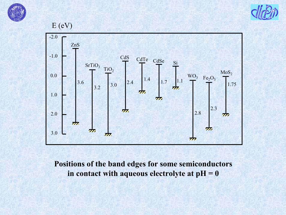

Gas-solid systems
Left photocatalytic paintingRight normal painting
Painting walls in highways
Photocatalytic decomposition and super hydrophilicity keep the surface of materials clean
PHOTOCATALYTIC TITANIA PAINTING
TITANIA-COATED PARTITION WALL PANELS
Gas-solid systems
The chemical industry is characterised by the almost exclusiveuse of continuous processes This type of operation calls forcontinuous (flow) reactors The need to fulfil the requirement of continuous operationdetermines that the photocatalyst powder for potential applicationpurposes should present suitable size and mechanical and fluidodynamic characteristics in addition to good catalyticproperties
PERSPECTIVES FOR APPLICATION OF HETEROGENEOUS PHOTOCATALYSIS IN LIQUID-SOLID SYSTEMS1
The difficulty to make a clear assessment of the costs or the expensiveness of the photocatalytic processes have prevented a wider development of them by an application point of view
1 L Palmisano Ed Processi e Metodologie per il Trattamento delle Acque Spiegel Milan 2000
Nanostructured photocatalysts have been reportedrecently to be more efficient (size quantization effect) than the bulk polycrystalline ones The use of thesematerials implies difficulties in their separation from the liquid phase consequently their application seems more promising for the preparation of thin films on variousrigid supports
An example of a possible application of heterogeneous photocatalysis is the photodegradation (polycrystalline TiO2 as the photocatalyst) of divinylsulfone (DVS) used as a crosslinkerfor the preparation of a biodegradable cellulose based superabsorbent hydrogel23
This material was obtained by chemical crosslinking of cellulose polyelectrolyte derivatives Carboxymethylcellulose (CMC) and Hydroxyethylcellulose (HEC) using DVS as the crosslinkerwhich covalently bounds different polymer molecules in a 3D hydrophilic networkSuperabsorbent hydrogels are used mainly for personal care products biosensing etc
Liquid-solid system
2 MA Del Nobile F Esposito G Mensitieri A Sannino Patent WO 98586863 G Marcigrave G Mele L Palmisano P Pulito A Sannino submitted
Gel before absorption of water
Gel after absorptionof water
A drawback for an industrial application is the large amount of water needed to wash the hydrogel before its desiccation
DVS is a well known toxic agent and it is present in low concentrations (ca 30-200 mgL-1) in washing waters deriving from the preparation together with the unreacted polymers and oligomers
TiO2 TiO2C4H6SO2 rarr intermediates rarr CO2 + H2O + SO4
2-
hν hν
This is a fortunate case because the concentration of pollutants to be photodegraded is quite low consequently to use other kinds of technologies could be not convenient
Moreover it is worth noting that the initial concentration of DVS can be modulated not only as a function of the degree of crosslinking to be induced in the network but also in order to obtain more diluted solutions to be treated more efficiently by heterogeneous photocatalysis
The purification of the washing water could allow its re-utilization making interesting the process both by an environmental and economical point of view
The idea is to couple a photocatalytic reactor with the pilot plant (that is coming to be built) for the production of the hydrogel
0
10
20
30
40
0 1 2 3 4 5 6Time [h]
TO
C [m
gmiddotL
-1]
darkultrasound
0
10
20
30
40
0 1 2 3 4 5 6Time [h]
TO
C [m
gmiddotL
-1]
darkultrasound
Total organic carbon concentration (TOC) versus time carried out by using a diluted solution and a 05 h ultrasound pre-treatment TOC initial concentration 313 mgmiddotL-1 (405 mgmiddotL-1 after sonication)
TOC concentration increases during the ultrasound treatment from 313 mgmiddotL-1 to 405 mgmiddotL-1 due to breaking of small pieces of hydrogel present in the solution 5 hours are needed for the complete disappearance of TOC
Photocatalyst TiO2 Degussa P25 08 gmiddotL-1Photoreactor 05 L batch photoreactor of cylindrical shapeLamp 125 W medium pressure Hg lamp
Run carried out by starting from an initial TOC concentration of 313 mgmiddotL-1 (405 mgmiddotL-1 after sonication)
A plateau is achieved after 5 hours irradiation time corresponding to the complete disappearance of TOCThe plateau corresponds to an initial TOC concentration due to DVS equal to ca21 mgmiddotL-1 Consequently ca 19 mgmiddotL-1 of TOC can be attributed to other organic species (unreacted polymers andor oligomers used during the preparation)
0
10
20
30
40
50
0 54321 6
Time [h]
Sulfa
teco
ncen
trat
ion
[mgmiddot
L-1
]
0
10
20
30
40
50
0 54321 6
Time [h]
Sulfa
teco
ncen
trat
ion
[mgmiddot
L-1
]
Summary
DICDICP MP M
Photocatalysis an overviewCoupling photocatalysis with other technologies
Biological treatment and Photofenton
Microwaves
Ozonation
Membrane reactorElectrochemical treatment
Biological methodologies Some substances are bio-resistant while photocatalysis is not specific for parti-cular substrates
It has been investigated the possibility to couple biological methods with some photochemical methods
Some pollutants as for instance metobromuron and isoproturon (herbicides) and AMBI (5-amino-6-methyl-2-benzimidazolone used in the manufacture of dyes) are biorecalcitrant molecules1-3
1 S Parra V Sarria S Malato P Peringer C Pulgarin Appl Catal B Environ 27 (2000) 153
2 C Pulgarin M Invernizzi S Parra V Sarria R Polania P Peringer Catal Today 54 (1999) 341
3 V Sarria P Peringer J Caceres J Blanco S Malato C Pulgarin Energy 29 (2004) 853
An exhaustive study was carried out for AMBI with different photocatalytic systems3 In order to enhance its biodegradability solar photocatalytic degradation methods were explored by using a pilot plant (Compound Parabolic Collector CPCrsquos) at the PlataformaSolar de Almeria consisting of three modules (each module consists of eight tubes collector surface 308 m2 photoreactor volume 22 l and total reactor volume 39 l)
LightTiO2O2LightFe3+O2LightTiO2H2O2LightFe3+H2O2
Evolution of DOC during AMBI degradation as a function of the accumulated solar energy AMBI (10 mmolmiddotl-1) H2O2 (11 mmolmiddotl-1) TiO2 (1 gl-1) and Fe3+ (10 mmolmiddotl-1) QUV is the accumulated energy (per unit of volume kJmiddotl-1) incident on the reactor for each sample taken during the experiment
Homogeneous systems indeed according to the point of view of AA show probably the best engineering conditionsThe concentrations of Fe3+ and H2O2 and the amount of TiO2 should be considered in these systems
AA despite the LightTiO2H2O2 system shows the most significant decrease of DOC suggest that the LightFe3+O2 and LightFe3+H2O2 systems could be chosen to be coupled with a biological process
In old papers an optimum of concentration of Fe3+ andor H2O2 hasbeen found for phenol photodegradation45
5 V Augugliaro E Davigrave L Palmisano M Schiavello A Sclafani Appl Catal 65 (1990) 101
4 A Sclafani L Palmisano E Davigrave J Photochem Photobiol A Chem 56 (1991) 113
CC0 vs reaction time TiO2 anatase (05 g l-1) in the presence of oxygen and various Fe3+ concentrations 5middot10-4 M (a) 1middot10-3 M (b) 25middot10-3 M (c) 5middot10-3 M (d) 5middot10-2 M (e) 1middot10-4 M (brsquo) 5middot10-5 M (crsquo) 1middot10-5 M (drsquo)Initial phenol concentration C0 = 10-3 M
A study on coupling photochemical and biological flow reactorsfor the degradation of p-nitrotoluene-ortho-sulfonic acid (p-NTS) has been carried out6
a) p-NTS (presence of nitro and sulphate electron withdrawinggroups) is present in effluents from the Swiss chemical industry
b) The mineralization of p-NTS via photo-Fenton treatment in batch or continuous mode is not a cost-effective strategy
c) p-NTS is not satisfactorily mineralized by heterogeneousphotocatalysis (TiO2H2O2)7
6 V Sarria P Peringer J Caacuteceres J Blanco S Malato C Pulgarin Energy 29 (2004) 8537 L Minsker C Pulgarin P Peringer J Kiwi New J Chem 18 (1994) 793
Schematic drawingof coupled photo-Fenton-biologicalflow reactor
Photochemical reactor Lamp 400 W medium pressure Hg lamp Mixing flask 1 1 L p-NTSsolution fed into the coil reactor from a 20 L feeding tank DOC concentrations up toca 350 mgL H2O2 automatically added by means of the peristaltic pump 1 Solution re-circulated at 22 Lh through the illuminated part of the reactor by pump 4 pH neutralised byNaOH at the outlet of the reactor via pump 3
Fixed bed bioreactor column containing biolite colonised by activated sludge and having 1 L of water capacity The effluent deriving from the photochemical stage was circulated fromflask 2 by the pump 5 through the bottom of the column pH was adjusted at 70 in flask 3 where the nutrients (N P K and oligoelements) for the bacterial activity were also added O2 concentration was controlled by an O2 probe at the top of the column
Schematic drawingof coupled photo-Fenton-biologicalflow reactor
The photo-assisted Fenton system used as a pre-treatmentgenerates in a very short period of time intermediates withvery oxidised functional groups not toxic and asbiodegradable as urban wastewater
The main parameter affecting the performance of the photo-assisted reactor in continuous mode is related to the high residual H2O2 concentration after the photochemical pre-treatment To overcome this inconvenience the semi-continuous mode was applied
A good efficiency was reached operating in semi-continuousmode before leading the treated water into the biologicalreactor the optimal time is 70 min
Summary
DICDICP MP M
Photocatalysis an overview
Coupling photocatalysis with other technologies
Biological treatment and Photofenton
Microwaves
Ozonation
Membrane reactor
Electrochemical treatment
Homogeneous system
O3 oxidation has been carried out in the past by using often oxalic acidoxalate ion as probe species
Ozone can react in aqueous solution with organicinorganic compounds by following two pathways
direct selective reaction with specific functional groups (double bonds nucleophilic positions)
reaction through free radicals generated from ozone decomposition
Hoignegrave and Bader1 investigated the ozonation of oxalic acidoxalate ion at various pHrsquos and concluded that the direct reaction can be considered negligible
The oxidation of oxalate ion at alkaline pHrsquos for example is due to attack by free radicals generated by O3 decomposition2
O3 + OH- rarr O2˙- + HO2
˙ (1)O3 + HO2
˙ rarr 2O2 + ˙OH (2)or alternatively2HO2
˙ rarr O2 + H2O2 (3) H2O2 + O2
˙- rarr OH- + ˙OH + O2 (4)The produced oxidant species can induce the mineralization of the oxalate anionC2O4
2- + 2˙OH rarr 2CO2 + 2OH- (5)
1 J Hoignegrave H Bader Water Res 17 (1983) 18
2 B Kasprzyk-Hordern M Zioacutelek J Nawrocki Appl Catal B Environ 46 (2003) 639
Heterogeneous system
When O3 is present in the photocatalytic suspension in addition to the homogeneous pathway described by reactions 1-4 the role of O3 as an electron trap must be considered
FTIR studies34 report different modes of ozone interaction with TiO2 surface such as
physical adsorptionformation of weak hydrogen bonds with surface hydroxyl groups of the catalystmolecular or dissociative adsorption on Lewis acid sites
3 Y Maeda A Fujishima K Honda J Electrochem Soc 128 (1981) 1731
4 KM Bulanin JC Lavalley AA Tsyganenko Colloid Surf A 101 (1995) 153
Strong surface Lewis acid sites lead to distortion of the ozone molecule affording its decomposition with formation of a free oxygen molecule and a surface oxygen atom that remains attached to the site4
O3 adsorbed onto TiO2 surface acts as a very strong electrophylicagent
O3(ads) + e-cb rarr O3˙- (6)
O3˙- + H2O rarr ˙OH + OH- + O2 (7)
The above reported mechanism gives rise to the formation of a hydroxyl radical per each trapped electron (reactions 6 and 7) whereas three electrons are needed for the generation of a hydroxyl radical when oxygen acts as electron trap (see reactions 8-11)
O2(ads) + e-(cb) rarr O2
˙- (8)
O2˙- + H2O rarr HO2
˙ + OH- (9)
2HO2˙ rarr O2 + H2O2 (10)
H2O2 + O2˙- rarr OH- + ˙OH + O2 (11)
Consequently when the photocatalyst is irradiated in the presence of O3a greater number of ˙OH radicals is produced
EPR studies5 moreover confirmed that O2 is less electrophylic than O3on respect to photogenerated electrons onto TiO2 surface
The above considerations can justify the observed positive effect of photocatalysis coupled with ozonation on the oxidation rate of oxalate anion6
5 MD Hernandez-Alonso JJ Coronado AJ Maira J Soria V Loddo V Augugliaro Appl Catal B Environ 39 (2002) 2576 M Addamo V Augugliaro E Garciacutea-Loacutepez V Loddo G Marcigrave L Palmisano Catalysis Today in press (paper presented during the XIX Iberoamerican Symposium of Catalysis)
Oxa
late
con
cent
ratio
n [M
] middot10
4
Time [s]
0
2
4
6
8
10
12
0 5000 10000 15000 20000
Comparison between oxalate ion degradation runs both in homogeneous and heterogeneous regimes6() O3airnear-UV () TiO2airnear-UV () TiO2O3airnear-UV () sum of the contribution of the substrate degradation of O3airnear-UV and TiO2airnear-UV
Lamp 700W medium pressure Hg lamp Photocatalyst 024 g L-1 TiO2 DegussaP25 [O3] = 81 10-4 M [O2] = 26 10-4 M
DICDICP MP M CIANIDE ION
CN- CNO-TiO2 hν TiO2 hν
NO2- + NO3
- + HCO3-CO3
2-
CN- CNO-
HCO3-CO3
2-
+
TiO2 hν TiO2 hν
TiO2 hνNH3 + (N2 NO N2O)
+ NO2-
H2O2
NO2- + NO3
-
NH2OH
TiO2 hν
Artificial light
Solar light
In
Out
Pyrextubing
Lampssupport
Stirrer
Electricpower
2500
2000
1700
Sedimentation zone
DICDICP MP M
PILOT PLANT ASSEMBLED AND TESTED IN THE GASIFICATION COAL POWER PLANT OF
PUERTOLLANO SPAIN
Reactor scheme
1500
500
140
150
PILOT PLANTDICDICP MP M
DICDICP MP M PILOT PLANT
PILOT PLANTDICDICP MP M
Experimental conditions of pilot plantDICDICP MP M
Liquid phase 24 m3middotd-1
Initial concentration of cianide Ci = 10 ppmFinal concentration of cianide Cf = 02 ppmReaction volume 24 m3
Total volume ca 6 m3
Used catalyst TiO2 (anatase) supported on Al2O3(particle size 90 ndash 110 μm)
Irradiating system consisted of 16 cilinder Pyrex tubes(lenght ca 2 m) Every tube contain 8 fluorescent lamps of 40 W (height 60 cm)
Electric power needed to mantein a turbulent regime into the reactor was 12 KW
Summary
DICDICP MP M
Photocatalysis an overviewCoupling photocatalysis with other technologies
Biological treatment and Photofenton
Microwaves
Ozonation
Membrane reactorElectrochemical treatment
This method presents versatility and simplicity of the reactors in terms of construction and management (particularly suitable for automation)1
Large application limited by the difficulty to findmaterials with specific characteristics to make the process competitive
1 K Rajeshwar and J Ibanez ldquoFundamentals and Applications in Pollution Abatementrdquo Academic Press New York 1997
TiPbO2 TiSnO2 TiIrO2 glassy carbon are generally used as the materials but some suffers for loss of activity due to surface fouling (glassy carbon) or limited service life (TiIrO2)
Silicon coated by a layer of synthetic diamond heavily doped with boron23 (to obtain acceptable electric conductivity) was proposed as anode for the oxidation of organic compounds4
On this boron-doped diamond (BDD) anode discharge of water does not occur in a wide potential range
2 F Beck H Krohn W Kaiser M Fryda CP Klages L Schafer Electrochim Acta 44 (1998) 525
3 V Fisher D Gandini S Laufer E Blank Ch Comninellis Electrochim Acta 44 (1998) 521
4 M Panizza PA Michaud G Cerisola Ch Comninellis Electrochem Commun 3 (2001) 336
Some biorefractory organic compounds present in water (phenol5 4-chlorophenol6 surfactants7 diuronand dichloroaniline8 triazines and cyanuric acid9) weretreated successfully by using BDD anode
5 J Iniesta PA Michaud M Panizza G Cerisola A Aldaz C Comninellis Electrochim Acta 46(2001) 3573
6 MA Rodrigo PA Michaud I Duo M Panizza G Cerisola C Comninellis J Electrochem Soc 148 (2001) D60
7 G Lissens J Pieters M Verhaege L Pinoy W Verstraete Electrochim Acta 48 (2003) 1655
8 AM Polcaro M Mascia S Palmas A Vacca Electrochim Acta 49 (2004) 649
9 AM Polcaro A Vacca M Mascia S Palmas Electrochim Acta 50 (2005) 1841
In the last case oxidation of organic compounds at BDD anodes involves production of OH radicals scarcely adsorbed at BDD surface (they are consequently desorbed and can attack the organic pollutant)
BDD anode behaves like an OH radicals generator
Oxidation in the potential region of water stability can lead toelectrode fouling due to the formation of polymeric materials
The electrochemical process is competitive with other advanced oxidation processes (AOPs) when the oxidation is carried out in the potential region of water discharge (O2 evolution)
Schematic view of the three-electrode flow electrochemical cellused to oxidize 2-Cl-4-ethylamino-6-isopropylamino-135-triazine (ATR) and 2-Cl-44-diammino-135-triazine (DAA) and 246-tri-hydroxy-135-triazine (CA cyanuric acid)9
Electrolyte was fed to the cell perpendicularly to the centre of the anode (pollutants concentration 70-500 ppm depending on the molecule) A grid of stainless steel as the catode A disk of boron doped diamond (BDD) as the anodeA saturated calomel electrode (SCE) as the reference electrode
BDD electrode is effective to oxidise not only the ATR and DAA but also CA that is known to be refractory to most of advanced oxidation processes including heterogeneous photocatalysis10
The best operating conditions to photo-oxidise CA in the electrochemical reactor are not the best ones tophoto-oxidise the starting molecule (atrazine or some other triazine)
10 C Minero G Mariella V Maurino E Pelizzetti Langmuir 16 (2000) 2632
Heterogeneous photocatalysis is effective tophotodegrade atrazine and other triazine herbicides butCA represents the final oxidation product10
An intriguing future possibility could be to couple heterogeneous photocatalysis with the electrochemical technology to perform in a hybrid system the photocatalytic degradation of atrazine or some othertriazine followed by the electrochemical oxidation of CA
Summary
DICDICP MP M
Photocatalysis an overviewCoupling photocatalysis with other technologies
Biological treatment and Photofenton
Microwaves
Ozonation
Membrane reactorElectrochemical treatment
1) Photocatalyst deposited on the membrane
2) Photocatalyst in suspension confined by means of the membrane
3) Entrapment of the photocatalyst in a PSF membrane
4a) Irradiation of a photocatalytic reactor and catalyst in suspension confined by means of the membrane
4b) as 4a) but the system works in continuous regime
Membrane Technology coupled with Photocatalysis
(e)
(f)
(g)
(a)(b)
(c)
(d)
(f)(h)
(i)(l)
tangential flux
(a) oxygen cylinder(b) cylindrical reactor
with cooling jacket(c) thermostatted bath(d) power supply(e) medium pressure Hg
lamp with conicreflector
(f) manometer(g) rotameter(h) cell containing the
membrane(i) magnetic stirrer(l) pump
Scheme of the Total Recycled Batch Photoreactorsystem used with suspended catalyst
4a
(e)
(f)
(g)
(b)
(c)
(f)
(a)
(d)
(h)
(i)
(l)
(n)
(l)
(m)
(g)
tangential flux
(a) oxygen cylinder(b) cylindrical reactor
with cooling jacket(c) thermostatted bath(d) power supply(e) medium pressure
Hg lamp with conicreflector
(f) manometer(g) rotameter(h) cell containing the
membrane(i) magnetic stirrer(l) pump(m) feed reservoir(n) permeate reservoir
Scheme of the Continuous Photoreactor system used with suspended catalyst
4b
Among the various configurations presented the configuration 4b seems the most promising by an application point of view because it takes the advantages both of the classical photoreactors(catalyst in suspension) and of the membrane processes (separation at molecular level)
The best polymeric ultrafiltration membranes used (good photostability checked by SEM and TOC acceptable values of wpf rejection unfortunately negligible etc)
PAN (polyacrylonitrile)FS50PP (fluoride + polypropylene) GR51PP (polysulfone + polypropylene)
In order to improve the rejection effects polymeric nanofiltration membranes were used in the systems 4a and 4b The best ones were NF-PES-010 (more permeable polyethersulfone Hoechst) and N30F (less permeable modified polysulphone Hoechst)
The choice of the membrane depends on the size of the pollutants to be treated pH can influence very strongly the rejection (Donnan Exclusion)
4-NP concentration in the retentate and permeate versus time for continuous and recycle system configurations (T = 30 degC P = 35 bar [TiO2] = 1 gl [O2] = 22 ppm I = 36 mWcm2 tangential flowrate = 500 mlmin permeate flux = 10 lhmiddotm2) Membrane used N30F12
Time [h]
4 -n
itrop
Con
c [m
gmiddotl-1
]
1 R Molinari L Palmisano E Drioli and M Schiavello J Membrane Science 206 (2002) 399
0
10
20
30
40
0 2 4 6 8
Retentate cont systPermeate cont systRetentate recyclePermeate recycle
As an example a representative run for 4-NP photodegradation is shownFor the recycle system the 4-NP maximum Cpermeate is 4 mgl (10 with respect to the initial one) for the continuous system 7 mgl (17 with respect to the initial one)
2 R Molinari L Giorno E Orioli L Palmisano M Schiavello in ldquoNanofiltration Principles and Applicationsrdquo AI Schaumlfer AG Fane TDWaite (Eds) Elsevier Oxford UK 2005 Cap 18 pp 435-458 and references therein
In addition to 4-NP degradation tests were successfully carried out by using humic acids phenol benzoic acid olive mill wastewater organic dyes drugs
The membranes selected showed the capability to retain the photocatalyst and to reject partially organic species controlling the residence time in the reacting system
Further work is required to look for other types of membranes high rejection NF-type or low rejection reverse osmosis-typemembranes (To be efficient also when low molecular weightpollutants are studied)
Some tests by using sunlight (Plataforma solar de Almeria) to photodegrade lyncomicin3 were carried out
3 V Augugliaro E Garciacutea-Loacutepez V Loddo S Malato I Maldonado G Marcigrave R Molinari L Palmisano Solar Energy 79 (2005) 402
(A) switch valve (B) thermocouple (C) not-reacting tank(D) pump (E) regulation valve (F) manometer(G) membrane vessel (H) line under pressure (I) rotameter
(PFP) plug flow photoreactor
PFP 2
AB
C
D
PFP 1
C
Retentate
Perm
eate
A
A
B
ED
DF
A
A
GH
I
Scheme of the photoreacting batch systems
Commercial nanofiltration membrane modules (DL2540C and DK2540C Oslash=25 inch L=40 inch Permeare srl Italy) were used at an operative pressure of 4 bar
EXPERIMENTAL
(A) switch valve(B) thermocouple(C) not-reacting tank(D) pump(E) regulation valve(F) manometer(G) membrane vessel(H) line under
pressure (I) rotameter(L) feedtank(PFP) plug flow
photoreactor
PFP 1
C
Retentate
Perm
eate
A
A
B
E
D
DF
A
GH
E
Vent
I
L
Scheme of the photoreacting continuous system
0
10
20
30
40
50
60
70
80
90
0 1 2 3
C [μ
M]
E [einstein]
0
6
12
18
0 1 2 3
TO
C [p
pm]
E [einstein]
Lincomycin and TOC (in the inset) concentrations versus the cumulative photon energy E for runs carried out in total recirculation regimens by using the hybrid system with DK2540C membrane at different initial lincomycin concentrations 75 mM Retentate permeate 25 mM Retentate permeate Measurements error plusmn 33
E [einstein]
0
10
20
30
40
50
60
70
80
90
0 1 2 3
E [einstein]
0
6
12
18
0 1 2 30
C [μ
M] T
OC
[ppm
]
Lincomycin and TOC (in the inset) concentrations versus the cumulative photon energy E for runs carried out in total recirculation regimens by using the hybrid system with DL2540C membrane at different initial lincomycin concentrations 75 mM Retentate permeate 25 mM Retentate permeate (Measurements error plusmn 3)3
Lincomycin and TOC (in the inset) concentrations versus the cumulative photon energy E for runs carried out in continuous regimen by using the hybrid system at different initial lincomycinconcentrations DK2540C membrane 10 mM Retentate permeate DL2540C membrane 25 mM Retentate permeate (Measurements error plusmn 3)3
0
5
10
15
20
25
0 1 2 3 4
0
4
8
12
0 1 2 3 40
4
8
12
0 1 2 3 4
E [einstein]
E [einstein]
C [μ
M] T
OC
[ppm
]
It can be noticed a total organic carbon accumulation in the reacting volume This feature can be explained by considering that under the experimental conditions used the amount of photons entering the system per unit time are not sufficient to mineralise the organic carbon fed in the photoreactor per unit time
0
5
10
15
20
25
0 1 2 3 4
0
4
8
12
0 1 2 3 40
4
8
12
0 1 2 3 4
E [einstein]
E [einstein]
C [μ
M] T
OC
[ppm
]
Integrated processes Photocatalysis (PC) + Pervaporation (PV)
It has been demonstrated that the integration of Photocatalysis (PC) with a membrane separation process ie Pervaporation (PV) is a very promising method to improve the efficiency of the detoxification of water streams containing organic pollutants at low concentrationThe commercial pervaporation membranes are organophilic so that most of the organic compounds permeate preferentially with respect to water4-Chlorophenol has been used as a probe molecule and the disappearance rate (transformation in HQ and BQ) was highly improved1
1 C Roda F Santarelli Proc ldquoEngineering with Membranesrdquo Granada (Spain) June 3-6 (2001) vol I pp 334-339
PC + PV no integration represents the arithmetic sum of the removals of PC and PV acting alone The plot overstimates the performances of the two processes operating in series without integration because the second process of the series would in any case work with a smaller driving force (proportional to the 4-ClP concentration)The optimistic sum is everywhere lower than the plot representing the operation of the integrated process
Also PV takes advantage of PC that transforms a poorly permeablecompound (4-ClP) into highly permeable compounds (HQ and especially BQ)
It is worth noting that in the integrated process the quantity of permeate stream collected is very small on respect to the initial volume of water to be purified
Some synergy exists because PC is favoured by the continuous subtraction by PV of the intermediates that hinder the photocatalytic reaction competing with 4-ClP
Membrane cell
Pervaporation
Permeate
Liquid nitrogen traps
Tank
Photocatalyticreactor
UV lamp
Tovacuum
Summary
DICDICP MP M
Photocatalysis an overview
Coupling photocatalysis with other technologies
Biological treatment and Photofenton
Microwaves
Ozonation
Membrane reactor
Electrochemical treatment
Integrate Microwave ndash UV sources for photocatalytic reactionMicrowave assisted chemistry is performed using special reactorsof dielectric materials placed inside a microwave oven fed with high voltage magnetron sources emitting continuous or pulsed power (ca 2450 MHz)1-3
This technique has been used both in gas-solid system for the photodegradation of many organic molecules (carboxylic acids aldehydes phenolic substrates etc) adsorbed on TiO2(T=20divide200degC) and in liquid-solid systems for the photo-degradation of cationic rodhanine-B in aqueous TiO2 dispersionCNR (Italian National Centre of Research) took patents of new devices consisting of microwave-UV integrated electrodelesssources4
1 IH Tseng WC Chang JCS Wu Appl Catal B Environ 37 (2002) 37
2 ZH Ai P Yang XH Lu Fresenius Environ Bull 13 (2004) 550
3 S Horikoshi F Hojo H Hidaka N E Serpone Environ Sci Tech 38 (2004) 2198
4 I Longo A Ricci N Tosoratti Proc of XVI National Congress of Industrial Chemistry 2005 113
3
33
CONCLUSIONS
In contrast with the gas-solid systems (many applications) heterogeneous photocatalysis in liquid-solid system can be used alone only in some specific cases
A more useful perspective is to couple heterogeneous photocatalysis with other technologies
Coupling with biological electrochemical ozone membrane technologies appear promising
The use of sunlight is very intriguing but it should follow a systematic investigation on bench scale by using artificial light to have a better knowledge of the influence of some parameter on the photoreactivity
Vincenzo AugugliaroFull Professor of Principles of Chemical Engineering
Leonardo PalmisanoFull Professor of Chemistry
Mario SchiavelloFull Professor of Chemistry
Agatino Di PaolaAssociate Professor of Corrosion Science
Giuseppe Marcigrave Researcher of ChemistryVittorio Loddo Researcher of Principles of Chemical
EngineeringElisa Garciacutea-Loacutepez Researcher of ChemistryMaurizio Addamo Post-doc studentJlenia Cantavenera PhD studentMarianna Bellardita PhD student
UNIVERSITAgrave DEGLI STUDI DI PALERMOFACOLTAgrave DI INGEGNERIA
NATIONAL COLLABORATIONSUniversitagrave della Calabria Universitagrave di BergamoProf Enrico Drioli Prof Tullio CaronnaProf Raffaele MolinariProf Giovanni Golemme
Universitagrave di Trento CTG ndash Italcementi GroupProf Giovanni Carturan Dr Luigi CassarProf Renzo CampostriniDr Marco Ischia
Universitagrave di TorinoProf Alessandra Bianco-PrevotProf Salvatore ColucciaProf Gianmario MartraProf Claudio MineroProf Ezio PelizzettiProf Edmondo Pramauro
Universitagrave di LecceProf Giuseppe VasapolloDr Giuseppe Mele
Universitagrave di Palermo e CNRProf Giulio DeganelloProf Anna Maria VeneziaDr Nadia Liotta
INTERNATIONAL COLLABORATIONS
ALMERIA SPAINPlataforma Solar de Almeriacutea PSADr Sixto Malato RodriacuteguezDr Ignacio Maldonado
MADRID SPAINInstituto de Caacutetalisis y Petroleoquimica CSICProf Javier Soria RuizDr Joseacute Carlos ConesaDr Juan Coronado
SALAMANCA SPAIN ERLANGEN GERMANYDepartamento de Quimica Insitut fuumlr Anorganische ChemieUniversidad de Salamanca Universitaumlt Erlagen-NuumlrnbergProf Vicente Rives-Arnau Prof Horst KischProf Cristina Martiacuten
SAPPORO JAPANCatalysis Research CenterProf Bunsho Othani
BRADFORD UKDepartment of Physical Chemistry and Chemical TechnologyProf Roger I Bickley

0
10
20
30
40
0 1 2 3 4 5 6Time [h]
TO
C [m
gmiddotL
-1]
darkultrasound
0
10
20
30
40
0 1 2 3 4 5 6Time [h]
TO
C [m
gmiddotL
-1]
darkultrasound
Total organic carbon concentration (TOC) versus time carried out by using a diluted solution and a 05 h ultrasound pre-treatment TOC initial concentration 313 mgmiddotL-1 (405 mgmiddotL-1 after sonication)
TOC concentration increases during the ultrasound treatment from 313 mgmiddotL-1 to 405 mgmiddotL-1 due to breaking of small pieces of hydrogel present in the solution 5 hours are needed for the complete disappearance of TOC
Photocatalyst TiO2 Degussa P25 08 gmiddotL-1Photoreactor 05 L batch photoreactor of cylindrical shapeLamp 125 W medium pressure Hg lamp
Run carried out by starting from an initial TOC concentration of 313 mgmiddotL-1 (405 mgmiddotL-1 after sonication)
A plateau is achieved after 5 hours irradiation time corresponding to the complete disappearance of TOCThe plateau corresponds to an initial TOC concentration due to DVS equal to ca21 mgmiddotL-1 Consequently ca 19 mgmiddotL-1 of TOC can be attributed to other organic species (unreacted polymers andor oligomers used during the preparation)
0
10
20
30
40
50
0 54321 6
Time [h]
Sulfa
teco
ncen
trat
ion
[mgmiddot
L-1
]
0
10
20
30
40
50
0 54321 6
Time [h]
Sulfa
teco
ncen
trat
ion
[mgmiddot
L-1
]
Summary
DICDICP MP M
Photocatalysis an overviewCoupling photocatalysis with other technologies
Biological treatment and Photofenton
Microwaves
Ozonation
Membrane reactorElectrochemical treatment
Biological methodologies Some substances are bio-resistant while photocatalysis is not specific for parti-cular substrates
It has been investigated the possibility to couple biological methods with some photochemical methods
Some pollutants as for instance metobromuron and isoproturon (herbicides) and AMBI (5-amino-6-methyl-2-benzimidazolone used in the manufacture of dyes) are biorecalcitrant molecules1-3
1 S Parra V Sarria S Malato P Peringer C Pulgarin Appl Catal B Environ 27 (2000) 153
2 C Pulgarin M Invernizzi S Parra V Sarria R Polania P Peringer Catal Today 54 (1999) 341
3 V Sarria P Peringer J Caceres J Blanco S Malato C Pulgarin Energy 29 (2004) 853
An exhaustive study was carried out for AMBI with different photocatalytic systems3 In order to enhance its biodegradability solar photocatalytic degradation methods were explored by using a pilot plant (Compound Parabolic Collector CPCrsquos) at the PlataformaSolar de Almeria consisting of three modules (each module consists of eight tubes collector surface 308 m2 photoreactor volume 22 l and total reactor volume 39 l)
LightTiO2O2LightFe3+O2LightTiO2H2O2LightFe3+H2O2
Evolution of DOC during AMBI degradation as a function of the accumulated solar energy AMBI (10 mmolmiddotl-1) H2O2 (11 mmolmiddotl-1) TiO2 (1 gl-1) and Fe3+ (10 mmolmiddotl-1) QUV is the accumulated energy (per unit of volume kJmiddotl-1) incident on the reactor for each sample taken during the experiment
Homogeneous systems indeed according to the point of view of AA show probably the best engineering conditionsThe concentrations of Fe3+ and H2O2 and the amount of TiO2 should be considered in these systems
AA despite the LightTiO2H2O2 system shows the most significant decrease of DOC suggest that the LightFe3+O2 and LightFe3+H2O2 systems could be chosen to be coupled with a biological process
In old papers an optimum of concentration of Fe3+ andor H2O2 hasbeen found for phenol photodegradation45
5 V Augugliaro E Davigrave L Palmisano M Schiavello A Sclafani Appl Catal 65 (1990) 101
4 A Sclafani L Palmisano E Davigrave J Photochem Photobiol A Chem 56 (1991) 113
CC0 vs reaction time TiO2 anatase (05 g l-1) in the presence of oxygen and various Fe3+ concentrations 5middot10-4 M (a) 1middot10-3 M (b) 25middot10-3 M (c) 5middot10-3 M (d) 5middot10-2 M (e) 1middot10-4 M (brsquo) 5middot10-5 M (crsquo) 1middot10-5 M (drsquo)Initial phenol concentration C0 = 10-3 M
A study on coupling photochemical and biological flow reactorsfor the degradation of p-nitrotoluene-ortho-sulfonic acid (p-NTS) has been carried out6
a) p-NTS (presence of nitro and sulphate electron withdrawinggroups) is present in effluents from the Swiss chemical industry
b) The mineralization of p-NTS via photo-Fenton treatment in batch or continuous mode is not a cost-effective strategy
c) p-NTS is not satisfactorily mineralized by heterogeneousphotocatalysis (TiO2H2O2)7
6 V Sarria P Peringer J Caacuteceres J Blanco S Malato C Pulgarin Energy 29 (2004) 8537 L Minsker C Pulgarin P Peringer J Kiwi New J Chem 18 (1994) 793
Schematic drawingof coupled photo-Fenton-biologicalflow reactor
Photochemical reactor Lamp 400 W medium pressure Hg lamp Mixing flask 1 1 L p-NTSsolution fed into the coil reactor from a 20 L feeding tank DOC concentrations up toca 350 mgL H2O2 automatically added by means of the peristaltic pump 1 Solution re-circulated at 22 Lh through the illuminated part of the reactor by pump 4 pH neutralised byNaOH at the outlet of the reactor via pump 3
Fixed bed bioreactor column containing biolite colonised by activated sludge and having 1 L of water capacity The effluent deriving from the photochemical stage was circulated fromflask 2 by the pump 5 through the bottom of the column pH was adjusted at 70 in flask 3 where the nutrients (N P K and oligoelements) for the bacterial activity were also added O2 concentration was controlled by an O2 probe at the top of the column
Schematic drawingof coupled photo-Fenton-biologicalflow reactor
The photo-assisted Fenton system used as a pre-treatmentgenerates in a very short period of time intermediates withvery oxidised functional groups not toxic and asbiodegradable as urban wastewater
The main parameter affecting the performance of the photo-assisted reactor in continuous mode is related to the high residual H2O2 concentration after the photochemical pre-treatment To overcome this inconvenience the semi-continuous mode was applied
A good efficiency was reached operating in semi-continuousmode before leading the treated water into the biologicalreactor the optimal time is 70 min
Summary
DICDICP MP M
Photocatalysis an overview
Coupling photocatalysis with other technologies
Biological treatment and Photofenton
Microwaves
Ozonation
Membrane reactor
Electrochemical treatment
Homogeneous system
O3 oxidation has been carried out in the past by using often oxalic acidoxalate ion as probe species
Ozone can react in aqueous solution with organicinorganic compounds by following two pathways
direct selective reaction with specific functional groups (double bonds nucleophilic positions)
reaction through free radicals generated from ozone decomposition
Hoignegrave and Bader1 investigated the ozonation of oxalic acidoxalate ion at various pHrsquos and concluded that the direct reaction can be considered negligible
The oxidation of oxalate ion at alkaline pHrsquos for example is due to attack by free radicals generated by O3 decomposition2
O3 + OH- rarr O2˙- + HO2
˙ (1)O3 + HO2
˙ rarr 2O2 + ˙OH (2)or alternatively2HO2
˙ rarr O2 + H2O2 (3) H2O2 + O2
˙- rarr OH- + ˙OH + O2 (4)The produced oxidant species can induce the mineralization of the oxalate anionC2O4
2- + 2˙OH rarr 2CO2 + 2OH- (5)
1 J Hoignegrave H Bader Water Res 17 (1983) 18
2 B Kasprzyk-Hordern M Zioacutelek J Nawrocki Appl Catal B Environ 46 (2003) 639
Heterogeneous system
When O3 is present in the photocatalytic suspension in addition to the homogeneous pathway described by reactions 1-4 the role of O3 as an electron trap must be considered
FTIR studies34 report different modes of ozone interaction with TiO2 surface such as
physical adsorptionformation of weak hydrogen bonds with surface hydroxyl groups of the catalystmolecular or dissociative adsorption on Lewis acid sites
3 Y Maeda A Fujishima K Honda J Electrochem Soc 128 (1981) 1731
4 KM Bulanin JC Lavalley AA Tsyganenko Colloid Surf A 101 (1995) 153
Strong surface Lewis acid sites lead to distortion of the ozone molecule affording its decomposition with formation of a free oxygen molecule and a surface oxygen atom that remains attached to the site4
O3 adsorbed onto TiO2 surface acts as a very strong electrophylicagent
O3(ads) + e-cb rarr O3˙- (6)
O3˙- + H2O rarr ˙OH + OH- + O2 (7)
The above reported mechanism gives rise to the formation of a hydroxyl radical per each trapped electron (reactions 6 and 7) whereas three electrons are needed for the generation of a hydroxyl radical when oxygen acts as electron trap (see reactions 8-11)
O2(ads) + e-(cb) rarr O2
˙- (8)
O2˙- + H2O rarr HO2
˙ + OH- (9)
2HO2˙ rarr O2 + H2O2 (10)
H2O2 + O2˙- rarr OH- + ˙OH + O2 (11)
Consequently when the photocatalyst is irradiated in the presence of O3a greater number of ˙OH radicals is produced
EPR studies5 moreover confirmed that O2 is less electrophylic than O3on respect to photogenerated electrons onto TiO2 surface
The above considerations can justify the observed positive effect of photocatalysis coupled with ozonation on the oxidation rate of oxalate anion6
5 MD Hernandez-Alonso JJ Coronado AJ Maira J Soria V Loddo V Augugliaro Appl Catal B Environ 39 (2002) 2576 M Addamo V Augugliaro E Garciacutea-Loacutepez V Loddo G Marcigrave L Palmisano Catalysis Today in press (paper presented during the XIX Iberoamerican Symposium of Catalysis)
Oxa
late
con
cent
ratio
n [M
] middot10
4
Time [s]
0
2
4
6
8
10
12
0 5000 10000 15000 20000
Comparison between oxalate ion degradation runs both in homogeneous and heterogeneous regimes6() O3airnear-UV () TiO2airnear-UV () TiO2O3airnear-UV () sum of the contribution of the substrate degradation of O3airnear-UV and TiO2airnear-UV
Lamp 700W medium pressure Hg lamp Photocatalyst 024 g L-1 TiO2 DegussaP25 [O3] = 81 10-4 M [O2] = 26 10-4 M
DICDICP MP M CIANIDE ION
CN- CNO-TiO2 hν TiO2 hν
NO2- + NO3
- + HCO3-CO3
2-
CN- CNO-
HCO3-CO3
2-
+
TiO2 hν TiO2 hν
TiO2 hνNH3 + (N2 NO N2O)
+ NO2-
H2O2
NO2- + NO3
-
NH2OH
TiO2 hν
Artificial light
Solar light
In
Out
Pyrextubing
Lampssupport
Stirrer
Electricpower
2500
2000
1700
Sedimentation zone
DICDICP MP M
PILOT PLANT ASSEMBLED AND TESTED IN THE GASIFICATION COAL POWER PLANT OF
PUERTOLLANO SPAIN
Reactor scheme
1500
500
140
150
PILOT PLANTDICDICP MP M
DICDICP MP M PILOT PLANT
PILOT PLANTDICDICP MP M
Experimental conditions of pilot plantDICDICP MP M
Liquid phase 24 m3middotd-1
Initial concentration of cianide Ci = 10 ppmFinal concentration of cianide Cf = 02 ppmReaction volume 24 m3
Total volume ca 6 m3
Used catalyst TiO2 (anatase) supported on Al2O3(particle size 90 ndash 110 μm)
Irradiating system consisted of 16 cilinder Pyrex tubes(lenght ca 2 m) Every tube contain 8 fluorescent lamps of 40 W (height 60 cm)
Electric power needed to mantein a turbulent regime into the reactor was 12 KW
Summary
DICDICP MP M
Photocatalysis an overviewCoupling photocatalysis with other technologies
Biological treatment and Photofenton
Microwaves
Ozonation
Membrane reactorElectrochemical treatment
This method presents versatility and simplicity of the reactors in terms of construction and management (particularly suitable for automation)1
Large application limited by the difficulty to findmaterials with specific characteristics to make the process competitive
1 K Rajeshwar and J Ibanez ldquoFundamentals and Applications in Pollution Abatementrdquo Academic Press New York 1997
TiPbO2 TiSnO2 TiIrO2 glassy carbon are generally used as the materials but some suffers for loss of activity due to surface fouling (glassy carbon) or limited service life (TiIrO2)
Silicon coated by a layer of synthetic diamond heavily doped with boron23 (to obtain acceptable electric conductivity) was proposed as anode for the oxidation of organic compounds4
On this boron-doped diamond (BDD) anode discharge of water does not occur in a wide potential range
2 F Beck H Krohn W Kaiser M Fryda CP Klages L Schafer Electrochim Acta 44 (1998) 525
3 V Fisher D Gandini S Laufer E Blank Ch Comninellis Electrochim Acta 44 (1998) 521
4 M Panizza PA Michaud G Cerisola Ch Comninellis Electrochem Commun 3 (2001) 336
Some biorefractory organic compounds present in water (phenol5 4-chlorophenol6 surfactants7 diuronand dichloroaniline8 triazines and cyanuric acid9) weretreated successfully by using BDD anode
5 J Iniesta PA Michaud M Panizza G Cerisola A Aldaz C Comninellis Electrochim Acta 46(2001) 3573
6 MA Rodrigo PA Michaud I Duo M Panizza G Cerisola C Comninellis J Electrochem Soc 148 (2001) D60
7 G Lissens J Pieters M Verhaege L Pinoy W Verstraete Electrochim Acta 48 (2003) 1655
8 AM Polcaro M Mascia S Palmas A Vacca Electrochim Acta 49 (2004) 649
9 AM Polcaro A Vacca M Mascia S Palmas Electrochim Acta 50 (2005) 1841
In the last case oxidation of organic compounds at BDD anodes involves production of OH radicals scarcely adsorbed at BDD surface (they are consequently desorbed and can attack the organic pollutant)
BDD anode behaves like an OH radicals generator
Oxidation in the potential region of water stability can lead toelectrode fouling due to the formation of polymeric materials
The electrochemical process is competitive with other advanced oxidation processes (AOPs) when the oxidation is carried out in the potential region of water discharge (O2 evolution)
Schematic view of the three-electrode flow electrochemical cellused to oxidize 2-Cl-4-ethylamino-6-isopropylamino-135-triazine (ATR) and 2-Cl-44-diammino-135-triazine (DAA) and 246-tri-hydroxy-135-triazine (CA cyanuric acid)9
Electrolyte was fed to the cell perpendicularly to the centre of the anode (pollutants concentration 70-500 ppm depending on the molecule) A grid of stainless steel as the catode A disk of boron doped diamond (BDD) as the anodeA saturated calomel electrode (SCE) as the reference electrode
BDD electrode is effective to oxidise not only the ATR and DAA but also CA that is known to be refractory to most of advanced oxidation processes including heterogeneous photocatalysis10
The best operating conditions to photo-oxidise CA in the electrochemical reactor are not the best ones tophoto-oxidise the starting molecule (atrazine or some other triazine)
10 C Minero G Mariella V Maurino E Pelizzetti Langmuir 16 (2000) 2632
Heterogeneous photocatalysis is effective tophotodegrade atrazine and other triazine herbicides butCA represents the final oxidation product10
An intriguing future possibility could be to couple heterogeneous photocatalysis with the electrochemical technology to perform in a hybrid system the photocatalytic degradation of atrazine or some othertriazine followed by the electrochemical oxidation of CA
Summary
DICDICP MP M
Photocatalysis an overviewCoupling photocatalysis with other technologies
Biological treatment and Photofenton
Microwaves
Ozonation
Membrane reactorElectrochemical treatment
1) Photocatalyst deposited on the membrane
2) Photocatalyst in suspension confined by means of the membrane
3) Entrapment of the photocatalyst in a PSF membrane
4a) Irradiation of a photocatalytic reactor and catalyst in suspension confined by means of the membrane
4b) as 4a) but the system works in continuous regime
Membrane Technology coupled with Photocatalysis
(e)
(f)
(g)
(a)(b)
(c)
(d)
(f)(h)
(i)(l)
tangential flux
(a) oxygen cylinder(b) cylindrical reactor
with cooling jacket(c) thermostatted bath(d) power supply(e) medium pressure Hg
lamp with conicreflector
(f) manometer(g) rotameter(h) cell containing the
membrane(i) magnetic stirrer(l) pump
Scheme of the Total Recycled Batch Photoreactorsystem used with suspended catalyst
4a
(e)
(f)
(g)
(b)
(c)
(f)
(a)
(d)
(h)
(i)
(l)
(n)
(l)
(m)
(g)
tangential flux
(a) oxygen cylinder(b) cylindrical reactor
with cooling jacket(c) thermostatted bath(d) power supply(e) medium pressure
Hg lamp with conicreflector
(f) manometer(g) rotameter(h) cell containing the
membrane(i) magnetic stirrer(l) pump(m) feed reservoir(n) permeate reservoir
Scheme of the Continuous Photoreactor system used with suspended catalyst
4b
Among the various configurations presented the configuration 4b seems the most promising by an application point of view because it takes the advantages both of the classical photoreactors(catalyst in suspension) and of the membrane processes (separation at molecular level)
The best polymeric ultrafiltration membranes used (good photostability checked by SEM and TOC acceptable values of wpf rejection unfortunately negligible etc)
PAN (polyacrylonitrile)FS50PP (fluoride + polypropylene) GR51PP (polysulfone + polypropylene)
In order to improve the rejection effects polymeric nanofiltration membranes were used in the systems 4a and 4b The best ones were NF-PES-010 (more permeable polyethersulfone Hoechst) and N30F (less permeable modified polysulphone Hoechst)
The choice of the membrane depends on the size of the pollutants to be treated pH can influence very strongly the rejection (Donnan Exclusion)
4-NP concentration in the retentate and permeate versus time for continuous and recycle system configurations (T = 30 degC P = 35 bar [TiO2] = 1 gl [O2] = 22 ppm I = 36 mWcm2 tangential flowrate = 500 mlmin permeate flux = 10 lhmiddotm2) Membrane used N30F12
Time [h]
4 -n
itrop
Con
c [m
gmiddotl-1
]
1 R Molinari L Palmisano E Drioli and M Schiavello J Membrane Science 206 (2002) 399
0
10
20
30
40
0 2 4 6 8
Retentate cont systPermeate cont systRetentate recyclePermeate recycle
As an example a representative run for 4-NP photodegradation is shownFor the recycle system the 4-NP maximum Cpermeate is 4 mgl (10 with respect to the initial one) for the continuous system 7 mgl (17 with respect to the initial one)
2 R Molinari L Giorno E Orioli L Palmisano M Schiavello in ldquoNanofiltration Principles and Applicationsrdquo AI Schaumlfer AG Fane TDWaite (Eds) Elsevier Oxford UK 2005 Cap 18 pp 435-458 and references therein
In addition to 4-NP degradation tests were successfully carried out by using humic acids phenol benzoic acid olive mill wastewater organic dyes drugs
The membranes selected showed the capability to retain the photocatalyst and to reject partially organic species controlling the residence time in the reacting system
Further work is required to look for other types of membranes high rejection NF-type or low rejection reverse osmosis-typemembranes (To be efficient also when low molecular weightpollutants are studied)
Some tests by using sunlight (Plataforma solar de Almeria) to photodegrade lyncomicin3 were carried out
3 V Augugliaro E Garciacutea-Loacutepez V Loddo S Malato I Maldonado G Marcigrave R Molinari L Palmisano Solar Energy 79 (2005) 402
(A) switch valve (B) thermocouple (C) not-reacting tank(D) pump (E) regulation valve (F) manometer(G) membrane vessel (H) line under pressure (I) rotameter
(PFP) plug flow photoreactor
PFP 2
AB
C
D
PFP 1
C
Retentate
Perm
eate
A
A
B
ED
DF
A
A
GH
I
Scheme of the photoreacting batch systems
Commercial nanofiltration membrane modules (DL2540C and DK2540C Oslash=25 inch L=40 inch Permeare srl Italy) were used at an operative pressure of 4 bar
EXPERIMENTAL
(A) switch valve(B) thermocouple(C) not-reacting tank(D) pump(E) regulation valve(F) manometer(G) membrane vessel(H) line under
pressure (I) rotameter(L) feedtank(PFP) plug flow
photoreactor
PFP 1
C
Retentate
Perm
eate
A
A
B
E
D
DF
A
GH
E
Vent
I
L
Scheme of the photoreacting continuous system
0
10
20
30
40
50
60
70
80
90
0 1 2 3
C [μ
M]
E [einstein]
0
6
12
18
0 1 2 3
TO
C [p
pm]
E [einstein]
Lincomycin and TOC (in the inset) concentrations versus the cumulative photon energy E for runs carried out in total recirculation regimens by using the hybrid system with DK2540C membrane at different initial lincomycin concentrations 75 mM Retentate permeate 25 mM Retentate permeate Measurements error plusmn 33
E [einstein]
0
10
20
30
40
50
60
70
80
90
0 1 2 3
E [einstein]
0
6
12
18
0 1 2 30
C [μ
M] T
OC
[ppm
]
Lincomycin and TOC (in the inset) concentrations versus the cumulative photon energy E for runs carried out in total recirculation regimens by using the hybrid system with DL2540C membrane at different initial lincomycin concentrations 75 mM Retentate permeate 25 mM Retentate permeate (Measurements error plusmn 3)3
Lincomycin and TOC (in the inset) concentrations versus the cumulative photon energy E for runs carried out in continuous regimen by using the hybrid system at different initial lincomycinconcentrations DK2540C membrane 10 mM Retentate permeate DL2540C membrane 25 mM Retentate permeate (Measurements error plusmn 3)3
0
5
10
15
20
25
0 1 2 3 4
0
4
8
12
0 1 2 3 40
4
8
12
0 1 2 3 4
E [einstein]
E [einstein]
C [μ
M] T
OC
[ppm
]
It can be noticed a total organic carbon accumulation in the reacting volume This feature can be explained by considering that under the experimental conditions used the amount of photons entering the system per unit time are not sufficient to mineralise the organic carbon fed in the photoreactor per unit time
0
5
10
15
20
25
0 1 2 3 4
0
4
8
12
0 1 2 3 40
4
8
12
0 1 2 3 4
E [einstein]
E [einstein]
C [μ
M] T
OC
[ppm
]
Integrated processes Photocatalysis (PC) + Pervaporation (PV)
It has been demonstrated that the integration of Photocatalysis (PC) with a membrane separation process ie Pervaporation (PV) is a very promising method to improve the efficiency of the detoxification of water streams containing organic pollutants at low concentrationThe commercial pervaporation membranes are organophilic so that most of the organic compounds permeate preferentially with respect to water4-Chlorophenol has been used as a probe molecule and the disappearance rate (transformation in HQ and BQ) was highly improved1
1 C Roda F Santarelli Proc ldquoEngineering with Membranesrdquo Granada (Spain) June 3-6 (2001) vol I pp 334-339
PC + PV no integration represents the arithmetic sum of the removals of PC and PV acting alone The plot overstimates the performances of the two processes operating in series without integration because the second process of the series would in any case work with a smaller driving force (proportional to the 4-ClP concentration)The optimistic sum is everywhere lower than the plot representing the operation of the integrated process
Also PV takes advantage of PC that transforms a poorly permeablecompound (4-ClP) into highly permeable compounds (HQ and especially BQ)
It is worth noting that in the integrated process the quantity of permeate stream collected is very small on respect to the initial volume of water to be purified
Some synergy exists because PC is favoured by the continuous subtraction by PV of the intermediates that hinder the photocatalytic reaction competing with 4-ClP
Membrane cell
Pervaporation
Permeate
Liquid nitrogen traps
Tank
Photocatalyticreactor
UV lamp
Tovacuum
Summary
DICDICP MP M
Photocatalysis an overview
Coupling photocatalysis with other technologies
Biological treatment and Photofenton
Microwaves
Ozonation
Membrane reactor
Electrochemical treatment
Integrate Microwave ndash UV sources for photocatalytic reactionMicrowave assisted chemistry is performed using special reactorsof dielectric materials placed inside a microwave oven fed with high voltage magnetron sources emitting continuous or pulsed power (ca 2450 MHz)1-3
This technique has been used both in gas-solid system for the photodegradation of many organic molecules (carboxylic acids aldehydes phenolic substrates etc) adsorbed on TiO2(T=20divide200degC) and in liquid-solid systems for the photo-degradation of cationic rodhanine-B in aqueous TiO2 dispersionCNR (Italian National Centre of Research) took patents of new devices consisting of microwave-UV integrated electrodelesssources4
1 IH Tseng WC Chang JCS Wu Appl Catal B Environ 37 (2002) 37
2 ZH Ai P Yang XH Lu Fresenius Environ Bull 13 (2004) 550
3 S Horikoshi F Hojo H Hidaka N E Serpone Environ Sci Tech 38 (2004) 2198
4 I Longo A Ricci N Tosoratti Proc of XVI National Congress of Industrial Chemistry 2005 113
3
33
CONCLUSIONS
In contrast with the gas-solid systems (many applications) heterogeneous photocatalysis in liquid-solid system can be used alone only in some specific cases
A more useful perspective is to couple heterogeneous photocatalysis with other technologies
Coupling with biological electrochemical ozone membrane technologies appear promising
The use of sunlight is very intriguing but it should follow a systematic investigation on bench scale by using artificial light to have a better knowledge of the influence of some parameter on the photoreactivity
Vincenzo AugugliaroFull Professor of Principles of Chemical Engineering
Leonardo PalmisanoFull Professor of Chemistry
Mario SchiavelloFull Professor of Chemistry
Agatino Di PaolaAssociate Professor of Corrosion Science
Giuseppe Marcigrave Researcher of ChemistryVittorio Loddo Researcher of Principles of Chemical
EngineeringElisa Garciacutea-Loacutepez Researcher of ChemistryMaurizio Addamo Post-doc studentJlenia Cantavenera PhD studentMarianna Bellardita PhD student
UNIVERSITAgrave DEGLI STUDI DI PALERMOFACOLTAgrave DI INGEGNERIA
NATIONAL COLLABORATIONSUniversitagrave della Calabria Universitagrave di BergamoProf Enrico Drioli Prof Tullio CaronnaProf Raffaele MolinariProf Giovanni Golemme
Universitagrave di Trento CTG ndash Italcementi GroupProf Giovanni Carturan Dr Luigi CassarProf Renzo CampostriniDr Marco Ischia
Universitagrave di TorinoProf Alessandra Bianco-PrevotProf Salvatore ColucciaProf Gianmario MartraProf Claudio MineroProf Ezio PelizzettiProf Edmondo Pramauro
Universitagrave di LecceProf Giuseppe VasapolloDr Giuseppe Mele
Universitagrave di Palermo e CNRProf Giulio DeganelloProf Anna Maria VeneziaDr Nadia Liotta
INTERNATIONAL COLLABORATIONS
ALMERIA SPAINPlataforma Solar de Almeriacutea PSADr Sixto Malato RodriacuteguezDr Ignacio Maldonado
MADRID SPAINInstituto de Caacutetalisis y Petroleoquimica CSICProf Javier Soria RuizDr Joseacute Carlos ConesaDr Juan Coronado
SALAMANCA SPAIN ERLANGEN GERMANYDepartamento de Quimica Insitut fuumlr Anorganische ChemieUniversidad de Salamanca Universitaumlt Erlagen-NuumlrnbergProf Vicente Rives-Arnau Prof Horst KischProf Cristina Martiacuten
SAPPORO JAPANCatalysis Research CenterProf Bunsho Othani
BRADFORD UKDepartment of Physical Chemistry and Chemical TechnologyProf Roger I Bickley

Summary
DICDICP MP M
Photocatalysis an overviewCoupling photocatalysis with other technologies
Biological treatment and Photofenton
Microwaves
Ozonation
Membrane reactorElectrochemical treatment
Biological methodologies Some substances are bio-resistant while photocatalysis is not specific for parti-cular substrates
It has been investigated the possibility to couple biological methods with some photochemical methods
Some pollutants as for instance metobromuron and isoproturon (herbicides) and AMBI (5-amino-6-methyl-2-benzimidazolone used in the manufacture of dyes) are biorecalcitrant molecules1-3
1 S Parra V Sarria S Malato P Peringer C Pulgarin Appl Catal B Environ 27 (2000) 153
2 C Pulgarin M Invernizzi S Parra V Sarria R Polania P Peringer Catal Today 54 (1999) 341
3 V Sarria P Peringer J Caceres J Blanco S Malato C Pulgarin Energy 29 (2004) 853
An exhaustive study was carried out for AMBI with different photocatalytic systems3 In order to enhance its biodegradability solar photocatalytic degradation methods were explored by using a pilot plant (Compound Parabolic Collector CPCrsquos) at the PlataformaSolar de Almeria consisting of three modules (each module consists of eight tubes collector surface 308 m2 photoreactor volume 22 l and total reactor volume 39 l)
LightTiO2O2LightFe3+O2LightTiO2H2O2LightFe3+H2O2
Evolution of DOC during AMBI degradation as a function of the accumulated solar energy AMBI (10 mmolmiddotl-1) H2O2 (11 mmolmiddotl-1) TiO2 (1 gl-1) and Fe3+ (10 mmolmiddotl-1) QUV is the accumulated energy (per unit of volume kJmiddotl-1) incident on the reactor for each sample taken during the experiment
Homogeneous systems indeed according to the point of view of AA show probably the best engineering conditionsThe concentrations of Fe3+ and H2O2 and the amount of TiO2 should be considered in these systems
AA despite the LightTiO2H2O2 system shows the most significant decrease of DOC suggest that the LightFe3+O2 and LightFe3+H2O2 systems could be chosen to be coupled with a biological process
In old papers an optimum of concentration of Fe3+ andor H2O2 hasbeen found for phenol photodegradation45
5 V Augugliaro E Davigrave L Palmisano M Schiavello A Sclafani Appl Catal 65 (1990) 101
4 A Sclafani L Palmisano E Davigrave J Photochem Photobiol A Chem 56 (1991) 113
CC0 vs reaction time TiO2 anatase (05 g l-1) in the presence of oxygen and various Fe3+ concentrations 5middot10-4 M (a) 1middot10-3 M (b) 25middot10-3 M (c) 5middot10-3 M (d) 5middot10-2 M (e) 1middot10-4 M (brsquo) 5middot10-5 M (crsquo) 1middot10-5 M (drsquo)Initial phenol concentration C0 = 10-3 M
A study on coupling photochemical and biological flow reactorsfor the degradation of p-nitrotoluene-ortho-sulfonic acid (p-NTS) has been carried out6
a) p-NTS (presence of nitro and sulphate electron withdrawinggroups) is present in effluents from the Swiss chemical industry
b) The mineralization of p-NTS via photo-Fenton treatment in batch or continuous mode is not a cost-effective strategy
c) p-NTS is not satisfactorily mineralized by heterogeneousphotocatalysis (TiO2H2O2)7
6 V Sarria P Peringer J Caacuteceres J Blanco S Malato C Pulgarin Energy 29 (2004) 8537 L Minsker C Pulgarin P Peringer J Kiwi New J Chem 18 (1994) 793
Schematic drawingof coupled photo-Fenton-biologicalflow reactor
Photochemical reactor Lamp 400 W medium pressure Hg lamp Mixing flask 1 1 L p-NTSsolution fed into the coil reactor from a 20 L feeding tank DOC concentrations up toca 350 mgL H2O2 automatically added by means of the peristaltic pump 1 Solution re-circulated at 22 Lh through the illuminated part of the reactor by pump 4 pH neutralised byNaOH at the outlet of the reactor via pump 3
Fixed bed bioreactor column containing biolite colonised by activated sludge and having 1 L of water capacity The effluent deriving from the photochemical stage was circulated fromflask 2 by the pump 5 through the bottom of the column pH was adjusted at 70 in flask 3 where the nutrients (N P K and oligoelements) for the bacterial activity were also added O2 concentration was controlled by an O2 probe at the top of the column
Schematic drawingof coupled photo-Fenton-biologicalflow reactor
The photo-assisted Fenton system used as a pre-treatmentgenerates in a very short period of time intermediates withvery oxidised functional groups not toxic and asbiodegradable as urban wastewater
The main parameter affecting the performance of the photo-assisted reactor in continuous mode is related to the high residual H2O2 concentration after the photochemical pre-treatment To overcome this inconvenience the semi-continuous mode was applied
A good efficiency was reached operating in semi-continuousmode before leading the treated water into the biologicalreactor the optimal time is 70 min
Summary
DICDICP MP M
Photocatalysis an overview
Coupling photocatalysis with other technologies
Biological treatment and Photofenton
Microwaves
Ozonation
Membrane reactor
Electrochemical treatment
Homogeneous system
O3 oxidation has been carried out in the past by using often oxalic acidoxalate ion as probe species
Ozone can react in aqueous solution with organicinorganic compounds by following two pathways
direct selective reaction with specific functional groups (double bonds nucleophilic positions)
reaction through free radicals generated from ozone decomposition
Hoignegrave and Bader1 investigated the ozonation of oxalic acidoxalate ion at various pHrsquos and concluded that the direct reaction can be considered negligible
The oxidation of oxalate ion at alkaline pHrsquos for example is due to attack by free radicals generated by O3 decomposition2
O3 + OH- rarr O2˙- + HO2
˙ (1)O3 + HO2
˙ rarr 2O2 + ˙OH (2)or alternatively2HO2
˙ rarr O2 + H2O2 (3) H2O2 + O2
˙- rarr OH- + ˙OH + O2 (4)The produced oxidant species can induce the mineralization of the oxalate anionC2O4
2- + 2˙OH rarr 2CO2 + 2OH- (5)
1 J Hoignegrave H Bader Water Res 17 (1983) 18
2 B Kasprzyk-Hordern M Zioacutelek J Nawrocki Appl Catal B Environ 46 (2003) 639
Heterogeneous system
When O3 is present in the photocatalytic suspension in addition to the homogeneous pathway described by reactions 1-4 the role of O3 as an electron trap must be considered
FTIR studies34 report different modes of ozone interaction with TiO2 surface such as
physical adsorptionformation of weak hydrogen bonds with surface hydroxyl groups of the catalystmolecular or dissociative adsorption on Lewis acid sites
3 Y Maeda A Fujishima K Honda J Electrochem Soc 128 (1981) 1731
4 KM Bulanin JC Lavalley AA Tsyganenko Colloid Surf A 101 (1995) 153
Strong surface Lewis acid sites lead to distortion of the ozone molecule affording its decomposition with formation of a free oxygen molecule and a surface oxygen atom that remains attached to the site4
O3 adsorbed onto TiO2 surface acts as a very strong electrophylicagent
O3(ads) + e-cb rarr O3˙- (6)
O3˙- + H2O rarr ˙OH + OH- + O2 (7)
The above reported mechanism gives rise to the formation of a hydroxyl radical per each trapped electron (reactions 6 and 7) whereas three electrons are needed for the generation of a hydroxyl radical when oxygen acts as electron trap (see reactions 8-11)
O2(ads) + e-(cb) rarr O2
˙- (8)
O2˙- + H2O rarr HO2
˙ + OH- (9)
2HO2˙ rarr O2 + H2O2 (10)
H2O2 + O2˙- rarr OH- + ˙OH + O2 (11)
Consequently when the photocatalyst is irradiated in the presence of O3a greater number of ˙OH radicals is produced
EPR studies5 moreover confirmed that O2 is less electrophylic than O3on respect to photogenerated electrons onto TiO2 surface
The above considerations can justify the observed positive effect of photocatalysis coupled with ozonation on the oxidation rate of oxalate anion6
5 MD Hernandez-Alonso JJ Coronado AJ Maira J Soria V Loddo V Augugliaro Appl Catal B Environ 39 (2002) 2576 M Addamo V Augugliaro E Garciacutea-Loacutepez V Loddo G Marcigrave L Palmisano Catalysis Today in press (paper presented during the XIX Iberoamerican Symposium of Catalysis)
Oxa
late
con
cent
ratio
n [M
] middot10
4
Time [s]
0
2
4
6
8
10
12
0 5000 10000 15000 20000
Comparison between oxalate ion degradation runs both in homogeneous and heterogeneous regimes6() O3airnear-UV () TiO2airnear-UV () TiO2O3airnear-UV () sum of the contribution of the substrate degradation of O3airnear-UV and TiO2airnear-UV
Lamp 700W medium pressure Hg lamp Photocatalyst 024 g L-1 TiO2 DegussaP25 [O3] = 81 10-4 M [O2] = 26 10-4 M
DICDICP MP M CIANIDE ION
CN- CNO-TiO2 hν TiO2 hν
NO2- + NO3
- + HCO3-CO3
2-
CN- CNO-
HCO3-CO3
2-
+
TiO2 hν TiO2 hν
TiO2 hνNH3 + (N2 NO N2O)
+ NO2-
H2O2
NO2- + NO3
-
NH2OH
TiO2 hν
Artificial light
Solar light
In
Out
Pyrextubing
Lampssupport
Stirrer
Electricpower
2500
2000
1700
Sedimentation zone
DICDICP MP M
PILOT PLANT ASSEMBLED AND TESTED IN THE GASIFICATION COAL POWER PLANT OF
PUERTOLLANO SPAIN
Reactor scheme
1500
500
140
150
PILOT PLANTDICDICP MP M
DICDICP MP M PILOT PLANT
PILOT PLANTDICDICP MP M
Experimental conditions of pilot plantDICDICP MP M
Liquid phase 24 m3middotd-1
Initial concentration of cianide Ci = 10 ppmFinal concentration of cianide Cf = 02 ppmReaction volume 24 m3
Total volume ca 6 m3
Used catalyst TiO2 (anatase) supported on Al2O3(particle size 90 ndash 110 μm)
Irradiating system consisted of 16 cilinder Pyrex tubes(lenght ca 2 m) Every tube contain 8 fluorescent lamps of 40 W (height 60 cm)
Electric power needed to mantein a turbulent regime into the reactor was 12 KW
Summary
DICDICP MP M
Photocatalysis an overviewCoupling photocatalysis with other technologies
Biological treatment and Photofenton
Microwaves
Ozonation
Membrane reactorElectrochemical treatment
This method presents versatility and simplicity of the reactors in terms of construction and management (particularly suitable for automation)1
Large application limited by the difficulty to findmaterials with specific characteristics to make the process competitive
1 K Rajeshwar and J Ibanez ldquoFundamentals and Applications in Pollution Abatementrdquo Academic Press New York 1997
TiPbO2 TiSnO2 TiIrO2 glassy carbon are generally used as the materials but some suffers for loss of activity due to surface fouling (glassy carbon) or limited service life (TiIrO2)
Silicon coated by a layer of synthetic diamond heavily doped with boron23 (to obtain acceptable electric conductivity) was proposed as anode for the oxidation of organic compounds4
On this boron-doped diamond (BDD) anode discharge of water does not occur in a wide potential range
2 F Beck H Krohn W Kaiser M Fryda CP Klages L Schafer Electrochim Acta 44 (1998) 525
3 V Fisher D Gandini S Laufer E Blank Ch Comninellis Electrochim Acta 44 (1998) 521
4 M Panizza PA Michaud G Cerisola Ch Comninellis Electrochem Commun 3 (2001) 336
Some biorefractory organic compounds present in water (phenol5 4-chlorophenol6 surfactants7 diuronand dichloroaniline8 triazines and cyanuric acid9) weretreated successfully by using BDD anode
5 J Iniesta PA Michaud M Panizza G Cerisola A Aldaz C Comninellis Electrochim Acta 46(2001) 3573
6 MA Rodrigo PA Michaud I Duo M Panizza G Cerisola C Comninellis J Electrochem Soc 148 (2001) D60
7 G Lissens J Pieters M Verhaege L Pinoy W Verstraete Electrochim Acta 48 (2003) 1655
8 AM Polcaro M Mascia S Palmas A Vacca Electrochim Acta 49 (2004) 649
9 AM Polcaro A Vacca M Mascia S Palmas Electrochim Acta 50 (2005) 1841
In the last case oxidation of organic compounds at BDD anodes involves production of OH radicals scarcely adsorbed at BDD surface (they are consequently desorbed and can attack the organic pollutant)
BDD anode behaves like an OH radicals generator
Oxidation in the potential region of water stability can lead toelectrode fouling due to the formation of polymeric materials
The electrochemical process is competitive with other advanced oxidation processes (AOPs) when the oxidation is carried out in the potential region of water discharge (O2 evolution)
Schematic view of the three-electrode flow electrochemical cellused to oxidize 2-Cl-4-ethylamino-6-isopropylamino-135-triazine (ATR) and 2-Cl-44-diammino-135-triazine (DAA) and 246-tri-hydroxy-135-triazine (CA cyanuric acid)9
Electrolyte was fed to the cell perpendicularly to the centre of the anode (pollutants concentration 70-500 ppm depending on the molecule) A grid of stainless steel as the catode A disk of boron doped diamond (BDD) as the anodeA saturated calomel electrode (SCE) as the reference electrode
BDD electrode is effective to oxidise not only the ATR and DAA but also CA that is known to be refractory to most of advanced oxidation processes including heterogeneous photocatalysis10
The best operating conditions to photo-oxidise CA in the electrochemical reactor are not the best ones tophoto-oxidise the starting molecule (atrazine or some other triazine)
10 C Minero G Mariella V Maurino E Pelizzetti Langmuir 16 (2000) 2632
Heterogeneous photocatalysis is effective tophotodegrade atrazine and other triazine herbicides butCA represents the final oxidation product10
An intriguing future possibility could be to couple heterogeneous photocatalysis with the electrochemical technology to perform in a hybrid system the photocatalytic degradation of atrazine or some othertriazine followed by the electrochemical oxidation of CA
Summary
DICDICP MP M
Photocatalysis an overviewCoupling photocatalysis with other technologies
Biological treatment and Photofenton
Microwaves
Ozonation
Membrane reactorElectrochemical treatment
1) Photocatalyst deposited on the membrane
2) Photocatalyst in suspension confined by means of the membrane
3) Entrapment of the photocatalyst in a PSF membrane
4a) Irradiation of a photocatalytic reactor and catalyst in suspension confined by means of the membrane
4b) as 4a) but the system works in continuous regime
Membrane Technology coupled with Photocatalysis
(e)
(f)
(g)
(a)(b)
(c)
(d)
(f)(h)
(i)(l)
tangential flux
(a) oxygen cylinder(b) cylindrical reactor
with cooling jacket(c) thermostatted bath(d) power supply(e) medium pressure Hg
lamp with conicreflector
(f) manometer(g) rotameter(h) cell containing the
membrane(i) magnetic stirrer(l) pump
Scheme of the Total Recycled Batch Photoreactorsystem used with suspended catalyst
4a
(e)
(f)
(g)
(b)
(c)
(f)
(a)
(d)
(h)
(i)
(l)
(n)
(l)
(m)
(g)
tangential flux
(a) oxygen cylinder(b) cylindrical reactor
with cooling jacket(c) thermostatted bath(d) power supply(e) medium pressure
Hg lamp with conicreflector
(f) manometer(g) rotameter(h) cell containing the
membrane(i) magnetic stirrer(l) pump(m) feed reservoir(n) permeate reservoir
Scheme of the Continuous Photoreactor system used with suspended catalyst
4b
Among the various configurations presented the configuration 4b seems the most promising by an application point of view because it takes the advantages both of the classical photoreactors(catalyst in suspension) and of the membrane processes (separation at molecular level)
The best polymeric ultrafiltration membranes used (good photostability checked by SEM and TOC acceptable values of wpf rejection unfortunately negligible etc)
PAN (polyacrylonitrile)FS50PP (fluoride + polypropylene) GR51PP (polysulfone + polypropylene)
In order to improve the rejection effects polymeric nanofiltration membranes were used in the systems 4a and 4b The best ones were NF-PES-010 (more permeable polyethersulfone Hoechst) and N30F (less permeable modified polysulphone Hoechst)
The choice of the membrane depends on the size of the pollutants to be treated pH can influence very strongly the rejection (Donnan Exclusion)
4-NP concentration in the retentate and permeate versus time for continuous and recycle system configurations (T = 30 degC P = 35 bar [TiO2] = 1 gl [O2] = 22 ppm I = 36 mWcm2 tangential flowrate = 500 mlmin permeate flux = 10 lhmiddotm2) Membrane used N30F12
Time [h]
4 -n
itrop
Con
c [m
gmiddotl-1
]
1 R Molinari L Palmisano E Drioli and M Schiavello J Membrane Science 206 (2002) 399
0
10
20
30
40
0 2 4 6 8
Retentate cont systPermeate cont systRetentate recyclePermeate recycle
As an example a representative run for 4-NP photodegradation is shownFor the recycle system the 4-NP maximum Cpermeate is 4 mgl (10 with respect to the initial one) for the continuous system 7 mgl (17 with respect to the initial one)
2 R Molinari L Giorno E Orioli L Palmisano M Schiavello in ldquoNanofiltration Principles and Applicationsrdquo AI Schaumlfer AG Fane TDWaite (Eds) Elsevier Oxford UK 2005 Cap 18 pp 435-458 and references therein
In addition to 4-NP degradation tests were successfully carried out by using humic acids phenol benzoic acid olive mill wastewater organic dyes drugs
The membranes selected showed the capability to retain the photocatalyst and to reject partially organic species controlling the residence time in the reacting system
Further work is required to look for other types of membranes high rejection NF-type or low rejection reverse osmosis-typemembranes (To be efficient also when low molecular weightpollutants are studied)
Some tests by using sunlight (Plataforma solar de Almeria) to photodegrade lyncomicin3 were carried out
3 V Augugliaro E Garciacutea-Loacutepez V Loddo S Malato I Maldonado G Marcigrave R Molinari L Palmisano Solar Energy 79 (2005) 402
(A) switch valve (B) thermocouple (C) not-reacting tank(D) pump (E) regulation valve (F) manometer(G) membrane vessel (H) line under pressure (I) rotameter
(PFP) plug flow photoreactor
PFP 2
AB
C
D
PFP 1
C
Retentate
Perm
eate
A
A
B
ED
DF
A
A
GH
I
Scheme of the photoreacting batch systems
Commercial nanofiltration membrane modules (DL2540C and DK2540C Oslash=25 inch L=40 inch Permeare srl Italy) were used at an operative pressure of 4 bar
EXPERIMENTAL
(A) switch valve(B) thermocouple(C) not-reacting tank(D) pump(E) regulation valve(F) manometer(G) membrane vessel(H) line under
pressure (I) rotameter(L) feedtank(PFP) plug flow
photoreactor
PFP 1
C
Retentate
Perm
eate
A
A
B
E
D
DF
A
GH
E
Vent
I
L
Scheme of the photoreacting continuous system
0
10
20
30
40
50
60
70
80
90
0 1 2 3
C [μ
M]
E [einstein]
0
6
12
18
0 1 2 3
TO
C [p
pm]
E [einstein]
Lincomycin and TOC (in the inset) concentrations versus the cumulative photon energy E for runs carried out in total recirculation regimens by using the hybrid system with DK2540C membrane at different initial lincomycin concentrations 75 mM Retentate permeate 25 mM Retentate permeate Measurements error plusmn 33
E [einstein]
0
10
20
30
40
50
60
70
80
90
0 1 2 3
E [einstein]
0
6
12
18
0 1 2 30
C [μ
M] T
OC
[ppm
]
Lincomycin and TOC (in the inset) concentrations versus the cumulative photon energy E for runs carried out in total recirculation regimens by using the hybrid system with DL2540C membrane at different initial lincomycin concentrations 75 mM Retentate permeate 25 mM Retentate permeate (Measurements error plusmn 3)3
Lincomycin and TOC (in the inset) concentrations versus the cumulative photon energy E for runs carried out in continuous regimen by using the hybrid system at different initial lincomycinconcentrations DK2540C membrane 10 mM Retentate permeate DL2540C membrane 25 mM Retentate permeate (Measurements error plusmn 3)3
0
5
10
15
20
25
0 1 2 3 4
0
4
8
12
0 1 2 3 40
4
8
12
0 1 2 3 4
E [einstein]
E [einstein]
C [μ
M] T
OC
[ppm
]
It can be noticed a total organic carbon accumulation in the reacting volume This feature can be explained by considering that under the experimental conditions used the amount of photons entering the system per unit time are not sufficient to mineralise the organic carbon fed in the photoreactor per unit time
0
5
10
15
20
25
0 1 2 3 4
0
4
8
12
0 1 2 3 40
4
8
12
0 1 2 3 4
E [einstein]
E [einstein]
C [μ
M] T
OC
[ppm
]
Integrated processes Photocatalysis (PC) + Pervaporation (PV)
It has been demonstrated that the integration of Photocatalysis (PC) with a membrane separation process ie Pervaporation (PV) is a very promising method to improve the efficiency of the detoxification of water streams containing organic pollutants at low concentrationThe commercial pervaporation membranes are organophilic so that most of the organic compounds permeate preferentially with respect to water4-Chlorophenol has been used as a probe molecule and the disappearance rate (transformation in HQ and BQ) was highly improved1
1 C Roda F Santarelli Proc ldquoEngineering with Membranesrdquo Granada (Spain) June 3-6 (2001) vol I pp 334-339
PC + PV no integration represents the arithmetic sum of the removals of PC and PV acting alone The plot overstimates the performances of the two processes operating in series without integration because the second process of the series would in any case work with a smaller driving force (proportional to the 4-ClP concentration)The optimistic sum is everywhere lower than the plot representing the operation of the integrated process
Also PV takes advantage of PC that transforms a poorly permeablecompound (4-ClP) into highly permeable compounds (HQ and especially BQ)
It is worth noting that in the integrated process the quantity of permeate stream collected is very small on respect to the initial volume of water to be purified
Some synergy exists because PC is favoured by the continuous subtraction by PV of the intermediates that hinder the photocatalytic reaction competing with 4-ClP
Membrane cell
Pervaporation
Permeate
Liquid nitrogen traps
Tank
Photocatalyticreactor
UV lamp
Tovacuum
Summary
DICDICP MP M
Photocatalysis an overview
Coupling photocatalysis with other technologies
Biological treatment and Photofenton
Microwaves
Ozonation
Membrane reactor
Electrochemical treatment
Integrate Microwave ndash UV sources for photocatalytic reactionMicrowave assisted chemistry is performed using special reactorsof dielectric materials placed inside a microwave oven fed with high voltage magnetron sources emitting continuous or pulsed power (ca 2450 MHz)1-3
This technique has been used both in gas-solid system for the photodegradation of many organic molecules (carboxylic acids aldehydes phenolic substrates etc) adsorbed on TiO2(T=20divide200degC) and in liquid-solid systems for the photo-degradation of cationic rodhanine-B in aqueous TiO2 dispersionCNR (Italian National Centre of Research) took patents of new devices consisting of microwave-UV integrated electrodelesssources4
1 IH Tseng WC Chang JCS Wu Appl Catal B Environ 37 (2002) 37
2 ZH Ai P Yang XH Lu Fresenius Environ Bull 13 (2004) 550
3 S Horikoshi F Hojo H Hidaka N E Serpone Environ Sci Tech 38 (2004) 2198
4 I Longo A Ricci N Tosoratti Proc of XVI National Congress of Industrial Chemistry 2005 113
3
33
CONCLUSIONS
In contrast with the gas-solid systems (many applications) heterogeneous photocatalysis in liquid-solid system can be used alone only in some specific cases
A more useful perspective is to couple heterogeneous photocatalysis with other technologies
Coupling with biological electrochemical ozone membrane technologies appear promising
The use of sunlight is very intriguing but it should follow a systematic investigation on bench scale by using artificial light to have a better knowledge of the influence of some parameter on the photoreactivity
Vincenzo AugugliaroFull Professor of Principles of Chemical Engineering
Leonardo PalmisanoFull Professor of Chemistry
Mario SchiavelloFull Professor of Chemistry
Agatino Di PaolaAssociate Professor of Corrosion Science
Giuseppe Marcigrave Researcher of ChemistryVittorio Loddo Researcher of Principles of Chemical
EngineeringElisa Garciacutea-Loacutepez Researcher of ChemistryMaurizio Addamo Post-doc studentJlenia Cantavenera PhD studentMarianna Bellardita PhD student
UNIVERSITAgrave DEGLI STUDI DI PALERMOFACOLTAgrave DI INGEGNERIA
NATIONAL COLLABORATIONSUniversitagrave della Calabria Universitagrave di BergamoProf Enrico Drioli Prof Tullio CaronnaProf Raffaele MolinariProf Giovanni Golemme
Universitagrave di Trento CTG ndash Italcementi GroupProf Giovanni Carturan Dr Luigi CassarProf Renzo CampostriniDr Marco Ischia
Universitagrave di TorinoProf Alessandra Bianco-PrevotProf Salvatore ColucciaProf Gianmario MartraProf Claudio MineroProf Ezio PelizzettiProf Edmondo Pramauro
Universitagrave di LecceProf Giuseppe VasapolloDr Giuseppe Mele
Universitagrave di Palermo e CNRProf Giulio DeganelloProf Anna Maria VeneziaDr Nadia Liotta
INTERNATIONAL COLLABORATIONS
ALMERIA SPAINPlataforma Solar de Almeriacutea PSADr Sixto Malato RodriacuteguezDr Ignacio Maldonado
MADRID SPAINInstituto de Caacutetalisis y Petroleoquimica CSICProf Javier Soria RuizDr Joseacute Carlos ConesaDr Juan Coronado
SALAMANCA SPAIN ERLANGEN GERMANYDepartamento de Quimica Insitut fuumlr Anorganische ChemieUniversidad de Salamanca Universitaumlt Erlagen-NuumlrnbergProf Vicente Rives-Arnau Prof Horst KischProf Cristina Martiacuten
SAPPORO JAPANCatalysis Research CenterProf Bunsho Othani
BRADFORD UKDepartment of Physical Chemistry and Chemical TechnologyProf Roger I Bickley
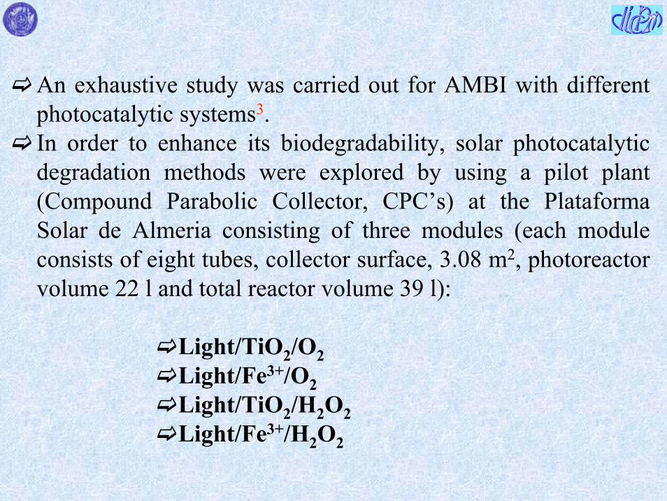

Schematic drawingof coupled photo-Fenton-biologicalflow reactor
Photochemical reactor Lamp 400 W medium pressure Hg lamp Mixing flask 1 1 L p-NTSsolution fed into the coil reactor from a 20 L feeding tank DOC concentrations up toca 350 mgL H2O2 automatically added by means of the peristaltic pump 1 Solution re-circulated at 22 Lh through the illuminated part of the reactor by pump 4 pH neutralised byNaOH at the outlet of the reactor via pump 3
Fixed bed bioreactor column containing biolite colonised by activated sludge and having 1 L of water capacity The effluent deriving from the photochemical stage was circulated fromflask 2 by the pump 5 through the bottom of the column pH was adjusted at 70 in flask 3 where the nutrients (N P K and oligoelements) for the bacterial activity were also added O2 concentration was controlled by an O2 probe at the top of the column
Schematic drawingof coupled photo-Fenton-biologicalflow reactor
The photo-assisted Fenton system used as a pre-treatmentgenerates in a very short period of time intermediates withvery oxidised functional groups not toxic and asbiodegradable as urban wastewater
The main parameter affecting the performance of the photo-assisted reactor in continuous mode is related to the high residual H2O2 concentration after the photochemical pre-treatment To overcome this inconvenience the semi-continuous mode was applied
A good efficiency was reached operating in semi-continuousmode before leading the treated water into the biologicalreactor the optimal time is 70 min
Summary
DICDICP MP M
Photocatalysis an overview
Coupling photocatalysis with other technologies
Biological treatment and Photofenton
Microwaves
Ozonation
Membrane reactor
Electrochemical treatment
Homogeneous system
O3 oxidation has been carried out in the past by using often oxalic acidoxalate ion as probe species
Ozone can react in aqueous solution with organicinorganic compounds by following two pathways
direct selective reaction with specific functional groups (double bonds nucleophilic positions)
reaction through free radicals generated from ozone decomposition
Hoignegrave and Bader1 investigated the ozonation of oxalic acidoxalate ion at various pHrsquos and concluded that the direct reaction can be considered negligible
The oxidation of oxalate ion at alkaline pHrsquos for example is due to attack by free radicals generated by O3 decomposition2
O3 + OH- rarr O2˙- + HO2
˙ (1)O3 + HO2
˙ rarr 2O2 + ˙OH (2)or alternatively2HO2
˙ rarr O2 + H2O2 (3) H2O2 + O2
˙- rarr OH- + ˙OH + O2 (4)The produced oxidant species can induce the mineralization of the oxalate anionC2O4
2- + 2˙OH rarr 2CO2 + 2OH- (5)
1 J Hoignegrave H Bader Water Res 17 (1983) 18
2 B Kasprzyk-Hordern M Zioacutelek J Nawrocki Appl Catal B Environ 46 (2003) 639
Heterogeneous system
When O3 is present in the photocatalytic suspension in addition to the homogeneous pathway described by reactions 1-4 the role of O3 as an electron trap must be considered
FTIR studies34 report different modes of ozone interaction with TiO2 surface such as
physical adsorptionformation of weak hydrogen bonds with surface hydroxyl groups of the catalystmolecular or dissociative adsorption on Lewis acid sites
3 Y Maeda A Fujishima K Honda J Electrochem Soc 128 (1981) 1731
4 KM Bulanin JC Lavalley AA Tsyganenko Colloid Surf A 101 (1995) 153
Strong surface Lewis acid sites lead to distortion of the ozone molecule affording its decomposition with formation of a free oxygen molecule and a surface oxygen atom that remains attached to the site4
O3 adsorbed onto TiO2 surface acts as a very strong electrophylicagent
O3(ads) + e-cb rarr O3˙- (6)
O3˙- + H2O rarr ˙OH + OH- + O2 (7)
The above reported mechanism gives rise to the formation of a hydroxyl radical per each trapped electron (reactions 6 and 7) whereas three electrons are needed for the generation of a hydroxyl radical when oxygen acts as electron trap (see reactions 8-11)
O2(ads) + e-(cb) rarr O2
˙- (8)
O2˙- + H2O rarr HO2
˙ + OH- (9)
2HO2˙ rarr O2 + H2O2 (10)
H2O2 + O2˙- rarr OH- + ˙OH + O2 (11)
Consequently when the photocatalyst is irradiated in the presence of O3a greater number of ˙OH radicals is produced
EPR studies5 moreover confirmed that O2 is less electrophylic than O3on respect to photogenerated electrons onto TiO2 surface
The above considerations can justify the observed positive effect of photocatalysis coupled with ozonation on the oxidation rate of oxalate anion6
5 MD Hernandez-Alonso JJ Coronado AJ Maira J Soria V Loddo V Augugliaro Appl Catal B Environ 39 (2002) 2576 M Addamo V Augugliaro E Garciacutea-Loacutepez V Loddo G Marcigrave L Palmisano Catalysis Today in press (paper presented during the XIX Iberoamerican Symposium of Catalysis)
Oxa
late
con
cent
ratio
n [M
] middot10
4
Time [s]
0
2
4
6
8
10
12
0 5000 10000 15000 20000
Comparison between oxalate ion degradation runs both in homogeneous and heterogeneous regimes6() O3airnear-UV () TiO2airnear-UV () TiO2O3airnear-UV () sum of the contribution of the substrate degradation of O3airnear-UV and TiO2airnear-UV
Lamp 700W medium pressure Hg lamp Photocatalyst 024 g L-1 TiO2 DegussaP25 [O3] = 81 10-4 M [O2] = 26 10-4 M
DICDICP MP M CIANIDE ION
CN- CNO-TiO2 hν TiO2 hν
NO2- + NO3
- + HCO3-CO3
2-
CN- CNO-
HCO3-CO3
2-
+
TiO2 hν TiO2 hν
TiO2 hνNH3 + (N2 NO N2O)
+ NO2-
H2O2
NO2- + NO3
-
NH2OH
TiO2 hν
Artificial light
Solar light
In
Out
Pyrextubing
Lampssupport
Stirrer
Electricpower
2500
2000
1700
Sedimentation zone
DICDICP MP M
PILOT PLANT ASSEMBLED AND TESTED IN THE GASIFICATION COAL POWER PLANT OF
PUERTOLLANO SPAIN
Reactor scheme
1500
500
140
150
PILOT PLANTDICDICP MP M
DICDICP MP M PILOT PLANT
PILOT PLANTDICDICP MP M
Experimental conditions of pilot plantDICDICP MP M
Liquid phase 24 m3middotd-1
Initial concentration of cianide Ci = 10 ppmFinal concentration of cianide Cf = 02 ppmReaction volume 24 m3
Total volume ca 6 m3
Used catalyst TiO2 (anatase) supported on Al2O3(particle size 90 ndash 110 μm)
Irradiating system consisted of 16 cilinder Pyrex tubes(lenght ca 2 m) Every tube contain 8 fluorescent lamps of 40 W (height 60 cm)
Electric power needed to mantein a turbulent regime into the reactor was 12 KW
Summary
DICDICP MP M
Photocatalysis an overviewCoupling photocatalysis with other technologies
Biological treatment and Photofenton
Microwaves
Ozonation
Membrane reactorElectrochemical treatment
This method presents versatility and simplicity of the reactors in terms of construction and management (particularly suitable for automation)1
Large application limited by the difficulty to findmaterials with specific characteristics to make the process competitive
1 K Rajeshwar and J Ibanez ldquoFundamentals and Applications in Pollution Abatementrdquo Academic Press New York 1997
TiPbO2 TiSnO2 TiIrO2 glassy carbon are generally used as the materials but some suffers for loss of activity due to surface fouling (glassy carbon) or limited service life (TiIrO2)
Silicon coated by a layer of synthetic diamond heavily doped with boron23 (to obtain acceptable electric conductivity) was proposed as anode for the oxidation of organic compounds4
On this boron-doped diamond (BDD) anode discharge of water does not occur in a wide potential range
2 F Beck H Krohn W Kaiser M Fryda CP Klages L Schafer Electrochim Acta 44 (1998) 525
3 V Fisher D Gandini S Laufer E Blank Ch Comninellis Electrochim Acta 44 (1998) 521
4 M Panizza PA Michaud G Cerisola Ch Comninellis Electrochem Commun 3 (2001) 336
Some biorefractory organic compounds present in water (phenol5 4-chlorophenol6 surfactants7 diuronand dichloroaniline8 triazines and cyanuric acid9) weretreated successfully by using BDD anode
5 J Iniesta PA Michaud M Panizza G Cerisola A Aldaz C Comninellis Electrochim Acta 46(2001) 3573
6 MA Rodrigo PA Michaud I Duo M Panizza G Cerisola C Comninellis J Electrochem Soc 148 (2001) D60
7 G Lissens J Pieters M Verhaege L Pinoy W Verstraete Electrochim Acta 48 (2003) 1655
8 AM Polcaro M Mascia S Palmas A Vacca Electrochim Acta 49 (2004) 649
9 AM Polcaro A Vacca M Mascia S Palmas Electrochim Acta 50 (2005) 1841
In the last case oxidation of organic compounds at BDD anodes involves production of OH radicals scarcely adsorbed at BDD surface (they are consequently desorbed and can attack the organic pollutant)
BDD anode behaves like an OH radicals generator
Oxidation in the potential region of water stability can lead toelectrode fouling due to the formation of polymeric materials
The electrochemical process is competitive with other advanced oxidation processes (AOPs) when the oxidation is carried out in the potential region of water discharge (O2 evolution)
Schematic view of the three-electrode flow electrochemical cellused to oxidize 2-Cl-4-ethylamino-6-isopropylamino-135-triazine (ATR) and 2-Cl-44-diammino-135-triazine (DAA) and 246-tri-hydroxy-135-triazine (CA cyanuric acid)9
Electrolyte was fed to the cell perpendicularly to the centre of the anode (pollutants concentration 70-500 ppm depending on the molecule) A grid of stainless steel as the catode A disk of boron doped diamond (BDD) as the anodeA saturated calomel electrode (SCE) as the reference electrode
BDD electrode is effective to oxidise not only the ATR and DAA but also CA that is known to be refractory to most of advanced oxidation processes including heterogeneous photocatalysis10
The best operating conditions to photo-oxidise CA in the electrochemical reactor are not the best ones tophoto-oxidise the starting molecule (atrazine or some other triazine)
10 C Minero G Mariella V Maurino E Pelizzetti Langmuir 16 (2000) 2632
Heterogeneous photocatalysis is effective tophotodegrade atrazine and other triazine herbicides butCA represents the final oxidation product10
An intriguing future possibility could be to couple heterogeneous photocatalysis with the electrochemical technology to perform in a hybrid system the photocatalytic degradation of atrazine or some othertriazine followed by the electrochemical oxidation of CA
Summary
DICDICP MP M
Photocatalysis an overviewCoupling photocatalysis with other technologies
Biological treatment and Photofenton
Microwaves
Ozonation
Membrane reactorElectrochemical treatment
1) Photocatalyst deposited on the membrane
2) Photocatalyst in suspension confined by means of the membrane
3) Entrapment of the photocatalyst in a PSF membrane
4a) Irradiation of a photocatalytic reactor and catalyst in suspension confined by means of the membrane
4b) as 4a) but the system works in continuous regime
Membrane Technology coupled with Photocatalysis
(e)
(f)
(g)
(a)(b)
(c)
(d)
(f)(h)
(i)(l)
tangential flux
(a) oxygen cylinder(b) cylindrical reactor
with cooling jacket(c) thermostatted bath(d) power supply(e) medium pressure Hg
lamp with conicreflector
(f) manometer(g) rotameter(h) cell containing the
membrane(i) magnetic stirrer(l) pump
Scheme of the Total Recycled Batch Photoreactorsystem used with suspended catalyst
4a
(e)
(f)
(g)
(b)
(c)
(f)
(a)
(d)
(h)
(i)
(l)
(n)
(l)
(m)
(g)
tangential flux
(a) oxygen cylinder(b) cylindrical reactor
with cooling jacket(c) thermostatted bath(d) power supply(e) medium pressure
Hg lamp with conicreflector
(f) manometer(g) rotameter(h) cell containing the
membrane(i) magnetic stirrer(l) pump(m) feed reservoir(n) permeate reservoir
Scheme of the Continuous Photoreactor system used with suspended catalyst
4b
Among the various configurations presented the configuration 4b seems the most promising by an application point of view because it takes the advantages both of the classical photoreactors(catalyst in suspension) and of the membrane processes (separation at molecular level)
The best polymeric ultrafiltration membranes used (good photostability checked by SEM and TOC acceptable values of wpf rejection unfortunately negligible etc)
PAN (polyacrylonitrile)FS50PP (fluoride + polypropylene) GR51PP (polysulfone + polypropylene)
In order to improve the rejection effects polymeric nanofiltration membranes were used in the systems 4a and 4b The best ones were NF-PES-010 (more permeable polyethersulfone Hoechst) and N30F (less permeable modified polysulphone Hoechst)
The choice of the membrane depends on the size of the pollutants to be treated pH can influence very strongly the rejection (Donnan Exclusion)
4-NP concentration in the retentate and permeate versus time for continuous and recycle system configurations (T = 30 degC P = 35 bar [TiO2] = 1 gl [O2] = 22 ppm I = 36 mWcm2 tangential flowrate = 500 mlmin permeate flux = 10 lhmiddotm2) Membrane used N30F12
Time [h]
4 -n
itrop
Con
c [m
gmiddotl-1
]
1 R Molinari L Palmisano E Drioli and M Schiavello J Membrane Science 206 (2002) 399
0
10
20
30
40
0 2 4 6 8
Retentate cont systPermeate cont systRetentate recyclePermeate recycle
As an example a representative run for 4-NP photodegradation is shownFor the recycle system the 4-NP maximum Cpermeate is 4 mgl (10 with respect to the initial one) for the continuous system 7 mgl (17 with respect to the initial one)
2 R Molinari L Giorno E Orioli L Palmisano M Schiavello in ldquoNanofiltration Principles and Applicationsrdquo AI Schaumlfer AG Fane TDWaite (Eds) Elsevier Oxford UK 2005 Cap 18 pp 435-458 and references therein
In addition to 4-NP degradation tests were successfully carried out by using humic acids phenol benzoic acid olive mill wastewater organic dyes drugs
The membranes selected showed the capability to retain the photocatalyst and to reject partially organic species controlling the residence time in the reacting system
Further work is required to look for other types of membranes high rejection NF-type or low rejection reverse osmosis-typemembranes (To be efficient also when low molecular weightpollutants are studied)
Some tests by using sunlight (Plataforma solar de Almeria) to photodegrade lyncomicin3 were carried out
3 V Augugliaro E Garciacutea-Loacutepez V Loddo S Malato I Maldonado G Marcigrave R Molinari L Palmisano Solar Energy 79 (2005) 402
(A) switch valve (B) thermocouple (C) not-reacting tank(D) pump (E) regulation valve (F) manometer(G) membrane vessel (H) line under pressure (I) rotameter
(PFP) plug flow photoreactor
PFP 2
AB
C
D
PFP 1
C
Retentate
Perm
eate
A
A
B
ED
DF
A
A
GH
I
Scheme of the photoreacting batch systems
Commercial nanofiltration membrane modules (DL2540C and DK2540C Oslash=25 inch L=40 inch Permeare srl Italy) were used at an operative pressure of 4 bar
EXPERIMENTAL
(A) switch valve(B) thermocouple(C) not-reacting tank(D) pump(E) regulation valve(F) manometer(G) membrane vessel(H) line under
pressure (I) rotameter(L) feedtank(PFP) plug flow
photoreactor
PFP 1
C
Retentate
Perm
eate
A
A
B
E
D
DF
A
GH
E
Vent
I
L
Scheme of the photoreacting continuous system
0
10
20
30
40
50
60
70
80
90
0 1 2 3
C [μ
M]
E [einstein]
0
6
12
18
0 1 2 3
TO
C [p
pm]
E [einstein]
Lincomycin and TOC (in the inset) concentrations versus the cumulative photon energy E for runs carried out in total recirculation regimens by using the hybrid system with DK2540C membrane at different initial lincomycin concentrations 75 mM Retentate permeate 25 mM Retentate permeate Measurements error plusmn 33
E [einstein]
0
10
20
30
40
50
60
70
80
90
0 1 2 3
E [einstein]
0
6
12
18
0 1 2 30
C [μ
M] T
OC
[ppm
]
Lincomycin and TOC (in the inset) concentrations versus the cumulative photon energy E for runs carried out in total recirculation regimens by using the hybrid system with DL2540C membrane at different initial lincomycin concentrations 75 mM Retentate permeate 25 mM Retentate permeate (Measurements error plusmn 3)3
Lincomycin and TOC (in the inset) concentrations versus the cumulative photon energy E for runs carried out in continuous regimen by using the hybrid system at different initial lincomycinconcentrations DK2540C membrane 10 mM Retentate permeate DL2540C membrane 25 mM Retentate permeate (Measurements error plusmn 3)3
0
5
10
15
20
25
0 1 2 3 4
0
4
8
12
0 1 2 3 40
4
8
12
0 1 2 3 4
E [einstein]
E [einstein]
C [μ
M] T
OC
[ppm
]
It can be noticed a total organic carbon accumulation in the reacting volume This feature can be explained by considering that under the experimental conditions used the amount of photons entering the system per unit time are not sufficient to mineralise the organic carbon fed in the photoreactor per unit time
0
5
10
15
20
25
0 1 2 3 4
0
4
8
12
0 1 2 3 40
4
8
12
0 1 2 3 4
E [einstein]
E [einstein]
C [μ
M] T
OC
[ppm
]
Integrated processes Photocatalysis (PC) + Pervaporation (PV)
It has been demonstrated that the integration of Photocatalysis (PC) with a membrane separation process ie Pervaporation (PV) is a very promising method to improve the efficiency of the detoxification of water streams containing organic pollutants at low concentrationThe commercial pervaporation membranes are organophilic so that most of the organic compounds permeate preferentially with respect to water4-Chlorophenol has been used as a probe molecule and the disappearance rate (transformation in HQ and BQ) was highly improved1
1 C Roda F Santarelli Proc ldquoEngineering with Membranesrdquo Granada (Spain) June 3-6 (2001) vol I pp 334-339
PC + PV no integration represents the arithmetic sum of the removals of PC and PV acting alone The plot overstimates the performances of the two processes operating in series without integration because the second process of the series would in any case work with a smaller driving force (proportional to the 4-ClP concentration)The optimistic sum is everywhere lower than the plot representing the operation of the integrated process
Also PV takes advantage of PC that transforms a poorly permeablecompound (4-ClP) into highly permeable compounds (HQ and especially BQ)
It is worth noting that in the integrated process the quantity of permeate stream collected is very small on respect to the initial volume of water to be purified
Some synergy exists because PC is favoured by the continuous subtraction by PV of the intermediates that hinder the photocatalytic reaction competing with 4-ClP
Membrane cell
Pervaporation
Permeate
Liquid nitrogen traps
Tank
Photocatalyticreactor
UV lamp
Tovacuum
Summary
DICDICP MP M
Photocatalysis an overview
Coupling photocatalysis with other technologies
Biological treatment and Photofenton
Microwaves
Ozonation
Membrane reactor
Electrochemical treatment
Integrate Microwave ndash UV sources for photocatalytic reactionMicrowave assisted chemistry is performed using special reactorsof dielectric materials placed inside a microwave oven fed with high voltage magnetron sources emitting continuous or pulsed power (ca 2450 MHz)1-3
This technique has been used both in gas-solid system for the photodegradation of many organic molecules (carboxylic acids aldehydes phenolic substrates etc) adsorbed on TiO2(T=20divide200degC) and in liquid-solid systems for the photo-degradation of cationic rodhanine-B in aqueous TiO2 dispersionCNR (Italian National Centre of Research) took patents of new devices consisting of microwave-UV integrated electrodelesssources4
1 IH Tseng WC Chang JCS Wu Appl Catal B Environ 37 (2002) 37
2 ZH Ai P Yang XH Lu Fresenius Environ Bull 13 (2004) 550
3 S Horikoshi F Hojo H Hidaka N E Serpone Environ Sci Tech 38 (2004) 2198
4 I Longo A Ricci N Tosoratti Proc of XVI National Congress of Industrial Chemistry 2005 113
3
33
CONCLUSIONS
In contrast with the gas-solid systems (many applications) heterogeneous photocatalysis in liquid-solid system can be used alone only in some specific cases
A more useful perspective is to couple heterogeneous photocatalysis with other technologies
Coupling with biological electrochemical ozone membrane technologies appear promising
The use of sunlight is very intriguing but it should follow a systematic investigation on bench scale by using artificial light to have a better knowledge of the influence of some parameter on the photoreactivity
Vincenzo AugugliaroFull Professor of Principles of Chemical Engineering
Leonardo PalmisanoFull Professor of Chemistry
Mario SchiavelloFull Professor of Chemistry
Agatino Di PaolaAssociate Professor of Corrosion Science
Giuseppe Marcigrave Researcher of ChemistryVittorio Loddo Researcher of Principles of Chemical
EngineeringElisa Garciacutea-Loacutepez Researcher of ChemistryMaurizio Addamo Post-doc studentJlenia Cantavenera PhD studentMarianna Bellardita PhD student
UNIVERSITAgrave DEGLI STUDI DI PALERMOFACOLTAgrave DI INGEGNERIA
NATIONAL COLLABORATIONSUniversitagrave della Calabria Universitagrave di BergamoProf Enrico Drioli Prof Tullio CaronnaProf Raffaele MolinariProf Giovanni Golemme
Universitagrave di Trento CTG ndash Italcementi GroupProf Giovanni Carturan Dr Luigi CassarProf Renzo CampostriniDr Marco Ischia
Universitagrave di TorinoProf Alessandra Bianco-PrevotProf Salvatore ColucciaProf Gianmario MartraProf Claudio MineroProf Ezio PelizzettiProf Edmondo Pramauro
Universitagrave di LecceProf Giuseppe VasapolloDr Giuseppe Mele
Universitagrave di Palermo e CNRProf Giulio DeganelloProf Anna Maria VeneziaDr Nadia Liotta
INTERNATIONAL COLLABORATIONS
ALMERIA SPAINPlataforma Solar de Almeriacutea PSADr Sixto Malato RodriacuteguezDr Ignacio Maldonado
MADRID SPAINInstituto de Caacutetalisis y Petroleoquimica CSICProf Javier Soria RuizDr Joseacute Carlos ConesaDr Juan Coronado
SALAMANCA SPAIN ERLANGEN GERMANYDepartamento de Quimica Insitut fuumlr Anorganische ChemieUniversidad de Salamanca Universitaumlt Erlagen-NuumlrnbergProf Vicente Rives-Arnau Prof Horst KischProf Cristina Martiacuten
SAPPORO JAPANCatalysis Research CenterProf Bunsho Othani
BRADFORD UKDepartment of Physical Chemistry and Chemical TechnologyProf Roger I Bickley

Summary
DICDICP MP M
Photocatalysis an overview
Coupling photocatalysis with other technologies
Biological treatment and Photofenton
Microwaves
Ozonation
Membrane reactor
Electrochemical treatment
Homogeneous system
O3 oxidation has been carried out in the past by using often oxalic acidoxalate ion as probe species
Ozone can react in aqueous solution with organicinorganic compounds by following two pathways
direct selective reaction with specific functional groups (double bonds nucleophilic positions)
reaction through free radicals generated from ozone decomposition
Hoignegrave and Bader1 investigated the ozonation of oxalic acidoxalate ion at various pHrsquos and concluded that the direct reaction can be considered negligible
The oxidation of oxalate ion at alkaline pHrsquos for example is due to attack by free radicals generated by O3 decomposition2
O3 + OH- rarr O2˙- + HO2
˙ (1)O3 + HO2
˙ rarr 2O2 + ˙OH (2)or alternatively2HO2
˙ rarr O2 + H2O2 (3) H2O2 + O2
˙- rarr OH- + ˙OH + O2 (4)The produced oxidant species can induce the mineralization of the oxalate anionC2O4
2- + 2˙OH rarr 2CO2 + 2OH- (5)
1 J Hoignegrave H Bader Water Res 17 (1983) 18
2 B Kasprzyk-Hordern M Zioacutelek J Nawrocki Appl Catal B Environ 46 (2003) 639
Heterogeneous system
When O3 is present in the photocatalytic suspension in addition to the homogeneous pathway described by reactions 1-4 the role of O3 as an electron trap must be considered
FTIR studies34 report different modes of ozone interaction with TiO2 surface such as
physical adsorptionformation of weak hydrogen bonds with surface hydroxyl groups of the catalystmolecular or dissociative adsorption on Lewis acid sites
3 Y Maeda A Fujishima K Honda J Electrochem Soc 128 (1981) 1731
4 KM Bulanin JC Lavalley AA Tsyganenko Colloid Surf A 101 (1995) 153
Strong surface Lewis acid sites lead to distortion of the ozone molecule affording its decomposition with formation of a free oxygen molecule and a surface oxygen atom that remains attached to the site4
O3 adsorbed onto TiO2 surface acts as a very strong electrophylicagent
O3(ads) + e-cb rarr O3˙- (6)
O3˙- + H2O rarr ˙OH + OH- + O2 (7)
The above reported mechanism gives rise to the formation of a hydroxyl radical per each trapped electron (reactions 6 and 7) whereas three electrons are needed for the generation of a hydroxyl radical when oxygen acts as electron trap (see reactions 8-11)
O2(ads) + e-(cb) rarr O2
˙- (8)
O2˙- + H2O rarr HO2
˙ + OH- (9)
2HO2˙ rarr O2 + H2O2 (10)
H2O2 + O2˙- rarr OH- + ˙OH + O2 (11)
Consequently when the photocatalyst is irradiated in the presence of O3a greater number of ˙OH radicals is produced
EPR studies5 moreover confirmed that O2 is less electrophylic than O3on respect to photogenerated electrons onto TiO2 surface
The above considerations can justify the observed positive effect of photocatalysis coupled with ozonation on the oxidation rate of oxalate anion6
5 MD Hernandez-Alonso JJ Coronado AJ Maira J Soria V Loddo V Augugliaro Appl Catal B Environ 39 (2002) 2576 M Addamo V Augugliaro E Garciacutea-Loacutepez V Loddo G Marcigrave L Palmisano Catalysis Today in press (paper presented during the XIX Iberoamerican Symposium of Catalysis)
Oxa
late
con
cent
ratio
n [M
] middot10
4
Time [s]
0
2
4
6
8
10
12
0 5000 10000 15000 20000
Comparison between oxalate ion degradation runs both in homogeneous and heterogeneous regimes6() O3airnear-UV () TiO2airnear-UV () TiO2O3airnear-UV () sum of the contribution of the substrate degradation of O3airnear-UV and TiO2airnear-UV
Lamp 700W medium pressure Hg lamp Photocatalyst 024 g L-1 TiO2 DegussaP25 [O3] = 81 10-4 M [O2] = 26 10-4 M
DICDICP MP M CIANIDE ION
CN- CNO-TiO2 hν TiO2 hν
NO2- + NO3
- + HCO3-CO3
2-
CN- CNO-
HCO3-CO3
2-
+
TiO2 hν TiO2 hν
TiO2 hνNH3 + (N2 NO N2O)
+ NO2-
H2O2
NO2- + NO3
-
NH2OH
TiO2 hν
Artificial light
Solar light
In
Out
Pyrextubing
Lampssupport
Stirrer
Electricpower
2500
2000
1700
Sedimentation zone
DICDICP MP M
PILOT PLANT ASSEMBLED AND TESTED IN THE GASIFICATION COAL POWER PLANT OF
PUERTOLLANO SPAIN
Reactor scheme
1500
500
140
150
PILOT PLANTDICDICP MP M
DICDICP MP M PILOT PLANT
PILOT PLANTDICDICP MP M
Experimental conditions of pilot plantDICDICP MP M
Liquid phase 24 m3middotd-1
Initial concentration of cianide Ci = 10 ppmFinal concentration of cianide Cf = 02 ppmReaction volume 24 m3
Total volume ca 6 m3
Used catalyst TiO2 (anatase) supported on Al2O3(particle size 90 ndash 110 μm)
Irradiating system consisted of 16 cilinder Pyrex tubes(lenght ca 2 m) Every tube contain 8 fluorescent lamps of 40 W (height 60 cm)
Electric power needed to mantein a turbulent regime into the reactor was 12 KW
Summary
DICDICP MP M
Photocatalysis an overviewCoupling photocatalysis with other technologies
Biological treatment and Photofenton
Microwaves
Ozonation
Membrane reactorElectrochemical treatment
This method presents versatility and simplicity of the reactors in terms of construction and management (particularly suitable for automation)1
Large application limited by the difficulty to findmaterials with specific characteristics to make the process competitive
1 K Rajeshwar and J Ibanez ldquoFundamentals and Applications in Pollution Abatementrdquo Academic Press New York 1997
TiPbO2 TiSnO2 TiIrO2 glassy carbon are generally used as the materials but some suffers for loss of activity due to surface fouling (glassy carbon) or limited service life (TiIrO2)
Silicon coated by a layer of synthetic diamond heavily doped with boron23 (to obtain acceptable electric conductivity) was proposed as anode for the oxidation of organic compounds4
On this boron-doped diamond (BDD) anode discharge of water does not occur in a wide potential range
2 F Beck H Krohn W Kaiser M Fryda CP Klages L Schafer Electrochim Acta 44 (1998) 525
3 V Fisher D Gandini S Laufer E Blank Ch Comninellis Electrochim Acta 44 (1998) 521
4 M Panizza PA Michaud G Cerisola Ch Comninellis Electrochem Commun 3 (2001) 336
Some biorefractory organic compounds present in water (phenol5 4-chlorophenol6 surfactants7 diuronand dichloroaniline8 triazines and cyanuric acid9) weretreated successfully by using BDD anode
5 J Iniesta PA Michaud M Panizza G Cerisola A Aldaz C Comninellis Electrochim Acta 46(2001) 3573
6 MA Rodrigo PA Michaud I Duo M Panizza G Cerisola C Comninellis J Electrochem Soc 148 (2001) D60
7 G Lissens J Pieters M Verhaege L Pinoy W Verstraete Electrochim Acta 48 (2003) 1655
8 AM Polcaro M Mascia S Palmas A Vacca Electrochim Acta 49 (2004) 649
9 AM Polcaro A Vacca M Mascia S Palmas Electrochim Acta 50 (2005) 1841
In the last case oxidation of organic compounds at BDD anodes involves production of OH radicals scarcely adsorbed at BDD surface (they are consequently desorbed and can attack the organic pollutant)
BDD anode behaves like an OH radicals generator
Oxidation in the potential region of water stability can lead toelectrode fouling due to the formation of polymeric materials
The electrochemical process is competitive with other advanced oxidation processes (AOPs) when the oxidation is carried out in the potential region of water discharge (O2 evolution)
Schematic view of the three-electrode flow electrochemical cellused to oxidize 2-Cl-4-ethylamino-6-isopropylamino-135-triazine (ATR) and 2-Cl-44-diammino-135-triazine (DAA) and 246-tri-hydroxy-135-triazine (CA cyanuric acid)9
Electrolyte was fed to the cell perpendicularly to the centre of the anode (pollutants concentration 70-500 ppm depending on the molecule) A grid of stainless steel as the catode A disk of boron doped diamond (BDD) as the anodeA saturated calomel electrode (SCE) as the reference electrode
BDD electrode is effective to oxidise not only the ATR and DAA but also CA that is known to be refractory to most of advanced oxidation processes including heterogeneous photocatalysis10
The best operating conditions to photo-oxidise CA in the electrochemical reactor are not the best ones tophoto-oxidise the starting molecule (atrazine or some other triazine)
10 C Minero G Mariella V Maurino E Pelizzetti Langmuir 16 (2000) 2632
Heterogeneous photocatalysis is effective tophotodegrade atrazine and other triazine herbicides butCA represents the final oxidation product10
An intriguing future possibility could be to couple heterogeneous photocatalysis with the electrochemical technology to perform in a hybrid system the photocatalytic degradation of atrazine or some othertriazine followed by the electrochemical oxidation of CA
Summary
DICDICP MP M
Photocatalysis an overviewCoupling photocatalysis with other technologies
Biological treatment and Photofenton
Microwaves
Ozonation
Membrane reactorElectrochemical treatment
1) Photocatalyst deposited on the membrane
2) Photocatalyst in suspension confined by means of the membrane
3) Entrapment of the photocatalyst in a PSF membrane
4a) Irradiation of a photocatalytic reactor and catalyst in suspension confined by means of the membrane
4b) as 4a) but the system works in continuous regime
Membrane Technology coupled with Photocatalysis
(e)
(f)
(g)
(a)(b)
(c)
(d)
(f)(h)
(i)(l)
tangential flux
(a) oxygen cylinder(b) cylindrical reactor
with cooling jacket(c) thermostatted bath(d) power supply(e) medium pressure Hg
lamp with conicreflector
(f) manometer(g) rotameter(h) cell containing the
membrane(i) magnetic stirrer(l) pump
Scheme of the Total Recycled Batch Photoreactorsystem used with suspended catalyst
4a
(e)
(f)
(g)
(b)
(c)
(f)
(a)
(d)
(h)
(i)
(l)
(n)
(l)
(m)
(g)
tangential flux
(a) oxygen cylinder(b) cylindrical reactor
with cooling jacket(c) thermostatted bath(d) power supply(e) medium pressure
Hg lamp with conicreflector
(f) manometer(g) rotameter(h) cell containing the
membrane(i) magnetic stirrer(l) pump(m) feed reservoir(n) permeate reservoir
Scheme of the Continuous Photoreactor system used with suspended catalyst
4b
Among the various configurations presented the configuration 4b seems the most promising by an application point of view because it takes the advantages both of the classical photoreactors(catalyst in suspension) and of the membrane processes (separation at molecular level)
The best polymeric ultrafiltration membranes used (good photostability checked by SEM and TOC acceptable values of wpf rejection unfortunately negligible etc)
PAN (polyacrylonitrile)FS50PP (fluoride + polypropylene) GR51PP (polysulfone + polypropylene)
In order to improve the rejection effects polymeric nanofiltration membranes were used in the systems 4a and 4b The best ones were NF-PES-010 (more permeable polyethersulfone Hoechst) and N30F (less permeable modified polysulphone Hoechst)
The choice of the membrane depends on the size of the pollutants to be treated pH can influence very strongly the rejection (Donnan Exclusion)
4-NP concentration in the retentate and permeate versus time for continuous and recycle system configurations (T = 30 degC P = 35 bar [TiO2] = 1 gl [O2] = 22 ppm I = 36 mWcm2 tangential flowrate = 500 mlmin permeate flux = 10 lhmiddotm2) Membrane used N30F12
Time [h]
4 -n
itrop
Con
c [m
gmiddotl-1
]
1 R Molinari L Palmisano E Drioli and M Schiavello J Membrane Science 206 (2002) 399
0
10
20
30
40
0 2 4 6 8
Retentate cont systPermeate cont systRetentate recyclePermeate recycle
As an example a representative run for 4-NP photodegradation is shownFor the recycle system the 4-NP maximum Cpermeate is 4 mgl (10 with respect to the initial one) for the continuous system 7 mgl (17 with respect to the initial one)
2 R Molinari L Giorno E Orioli L Palmisano M Schiavello in ldquoNanofiltration Principles and Applicationsrdquo AI Schaumlfer AG Fane TDWaite (Eds) Elsevier Oxford UK 2005 Cap 18 pp 435-458 and references therein
In addition to 4-NP degradation tests were successfully carried out by using humic acids phenol benzoic acid olive mill wastewater organic dyes drugs
The membranes selected showed the capability to retain the photocatalyst and to reject partially organic species controlling the residence time in the reacting system
Further work is required to look for other types of membranes high rejection NF-type or low rejection reverse osmosis-typemembranes (To be efficient also when low molecular weightpollutants are studied)
Some tests by using sunlight (Plataforma solar de Almeria) to photodegrade lyncomicin3 were carried out
3 V Augugliaro E Garciacutea-Loacutepez V Loddo S Malato I Maldonado G Marcigrave R Molinari L Palmisano Solar Energy 79 (2005) 402
(A) switch valve (B) thermocouple (C) not-reacting tank(D) pump (E) regulation valve (F) manometer(G) membrane vessel (H) line under pressure (I) rotameter
(PFP) plug flow photoreactor
PFP 2
AB
C
D
PFP 1
C
Retentate
Perm
eate
A
A
B
ED
DF
A
A
GH
I
Scheme of the photoreacting batch systems
Commercial nanofiltration membrane modules (DL2540C and DK2540C Oslash=25 inch L=40 inch Permeare srl Italy) were used at an operative pressure of 4 bar
EXPERIMENTAL
(A) switch valve(B) thermocouple(C) not-reacting tank(D) pump(E) regulation valve(F) manometer(G) membrane vessel(H) line under
pressure (I) rotameter(L) feedtank(PFP) plug flow
photoreactor
PFP 1
C
Retentate
Perm
eate
A
A
B
E
D
DF
A
GH
E
Vent
I
L
Scheme of the photoreacting continuous system
0
10
20
30
40
50
60
70
80
90
0 1 2 3
C [μ
M]
E [einstein]
0
6
12
18
0 1 2 3
TO
C [p
pm]
E [einstein]
Lincomycin and TOC (in the inset) concentrations versus the cumulative photon energy E for runs carried out in total recirculation regimens by using the hybrid system with DK2540C membrane at different initial lincomycin concentrations 75 mM Retentate permeate 25 mM Retentate permeate Measurements error plusmn 33
E [einstein]
0
10
20
30
40
50
60
70
80
90
0 1 2 3
E [einstein]
0
6
12
18
0 1 2 30
C [μ
M] T
OC
[ppm
]
Lincomycin and TOC (in the inset) concentrations versus the cumulative photon energy E for runs carried out in total recirculation regimens by using the hybrid system with DL2540C membrane at different initial lincomycin concentrations 75 mM Retentate permeate 25 mM Retentate permeate (Measurements error plusmn 3)3
Lincomycin and TOC (in the inset) concentrations versus the cumulative photon energy E for runs carried out in continuous regimen by using the hybrid system at different initial lincomycinconcentrations DK2540C membrane 10 mM Retentate permeate DL2540C membrane 25 mM Retentate permeate (Measurements error plusmn 3)3
0
5
10
15
20
25
0 1 2 3 4
0
4
8
12
0 1 2 3 40
4
8
12
0 1 2 3 4
E [einstein]
E [einstein]
C [μ
M] T
OC
[ppm
]
It can be noticed a total organic carbon accumulation in the reacting volume This feature can be explained by considering that under the experimental conditions used the amount of photons entering the system per unit time are not sufficient to mineralise the organic carbon fed in the photoreactor per unit time
0
5
10
15
20
25
0 1 2 3 4
0
4
8
12
0 1 2 3 40
4
8
12
0 1 2 3 4
E [einstein]
E [einstein]
C [μ
M] T
OC
[ppm
]
Integrated processes Photocatalysis (PC) + Pervaporation (PV)
It has been demonstrated that the integration of Photocatalysis (PC) with a membrane separation process ie Pervaporation (PV) is a very promising method to improve the efficiency of the detoxification of water streams containing organic pollutants at low concentrationThe commercial pervaporation membranes are organophilic so that most of the organic compounds permeate preferentially with respect to water4-Chlorophenol has been used as a probe molecule and the disappearance rate (transformation in HQ and BQ) was highly improved1
1 C Roda F Santarelli Proc ldquoEngineering with Membranesrdquo Granada (Spain) June 3-6 (2001) vol I pp 334-339
PC + PV no integration represents the arithmetic sum of the removals of PC and PV acting alone The plot overstimates the performances of the two processes operating in series without integration because the second process of the series would in any case work with a smaller driving force (proportional to the 4-ClP concentration)The optimistic sum is everywhere lower than the plot representing the operation of the integrated process
Also PV takes advantage of PC that transforms a poorly permeablecompound (4-ClP) into highly permeable compounds (HQ and especially BQ)
It is worth noting that in the integrated process the quantity of permeate stream collected is very small on respect to the initial volume of water to be purified
Some synergy exists because PC is favoured by the continuous subtraction by PV of the intermediates that hinder the photocatalytic reaction competing with 4-ClP
Membrane cell
Pervaporation
Permeate
Liquid nitrogen traps
Tank
Photocatalyticreactor
UV lamp
Tovacuum
Summary
DICDICP MP M
Photocatalysis an overview
Coupling photocatalysis with other technologies
Biological treatment and Photofenton
Microwaves
Ozonation
Membrane reactor
Electrochemical treatment
Integrate Microwave ndash UV sources for photocatalytic reactionMicrowave assisted chemistry is performed using special reactorsof dielectric materials placed inside a microwave oven fed with high voltage magnetron sources emitting continuous or pulsed power (ca 2450 MHz)1-3
This technique has been used both in gas-solid system for the photodegradation of many organic molecules (carboxylic acids aldehydes phenolic substrates etc) adsorbed on TiO2(T=20divide200degC) and in liquid-solid systems for the photo-degradation of cationic rodhanine-B in aqueous TiO2 dispersionCNR (Italian National Centre of Research) took patents of new devices consisting of microwave-UV integrated electrodelesssources4
1 IH Tseng WC Chang JCS Wu Appl Catal B Environ 37 (2002) 37
2 ZH Ai P Yang XH Lu Fresenius Environ Bull 13 (2004) 550
3 S Horikoshi F Hojo H Hidaka N E Serpone Environ Sci Tech 38 (2004) 2198
4 I Longo A Ricci N Tosoratti Proc of XVI National Congress of Industrial Chemistry 2005 113
3
33
CONCLUSIONS
In contrast with the gas-solid systems (many applications) heterogeneous photocatalysis in liquid-solid system can be used alone only in some specific cases
A more useful perspective is to couple heterogeneous photocatalysis with other technologies
Coupling with biological electrochemical ozone membrane technologies appear promising
The use of sunlight is very intriguing but it should follow a systematic investigation on bench scale by using artificial light to have a better knowledge of the influence of some parameter on the photoreactivity
Vincenzo AugugliaroFull Professor of Principles of Chemical Engineering
Leonardo PalmisanoFull Professor of Chemistry
Mario SchiavelloFull Professor of Chemistry
Agatino Di PaolaAssociate Professor of Corrosion Science
Giuseppe Marcigrave Researcher of ChemistryVittorio Loddo Researcher of Principles of Chemical
EngineeringElisa Garciacutea-Loacutepez Researcher of ChemistryMaurizio Addamo Post-doc studentJlenia Cantavenera PhD studentMarianna Bellardita PhD student
UNIVERSITAgrave DEGLI STUDI DI PALERMOFACOLTAgrave DI INGEGNERIA
NATIONAL COLLABORATIONSUniversitagrave della Calabria Universitagrave di BergamoProf Enrico Drioli Prof Tullio CaronnaProf Raffaele MolinariProf Giovanni Golemme
Universitagrave di Trento CTG ndash Italcementi GroupProf Giovanni Carturan Dr Luigi CassarProf Renzo CampostriniDr Marco Ischia
Universitagrave di TorinoProf Alessandra Bianco-PrevotProf Salvatore ColucciaProf Gianmario MartraProf Claudio MineroProf Ezio PelizzettiProf Edmondo Pramauro
Universitagrave di LecceProf Giuseppe VasapolloDr Giuseppe Mele
Universitagrave di Palermo e CNRProf Giulio DeganelloProf Anna Maria VeneziaDr Nadia Liotta
INTERNATIONAL COLLABORATIONS
ALMERIA SPAINPlataforma Solar de Almeriacutea PSADr Sixto Malato RodriacuteguezDr Ignacio Maldonado
MADRID SPAINInstituto de Caacutetalisis y Petroleoquimica CSICProf Javier Soria RuizDr Joseacute Carlos ConesaDr Juan Coronado
SALAMANCA SPAIN ERLANGEN GERMANYDepartamento de Quimica Insitut fuumlr Anorganische ChemieUniversidad de Salamanca Universitaumlt Erlagen-NuumlrnbergProf Vicente Rives-Arnau Prof Horst KischProf Cristina Martiacuten
SAPPORO JAPANCatalysis Research CenterProf Bunsho Othani
BRADFORD UKDepartment of Physical Chemistry and Chemical TechnologyProf Roger I Bickley

PILOT PLANTDICDICP MP M
DICDICP MP M PILOT PLANT
PILOT PLANTDICDICP MP M
Experimental conditions of pilot plantDICDICP MP M
Liquid phase 24 m3middotd-1
Initial concentration of cianide Ci = 10 ppmFinal concentration of cianide Cf = 02 ppmReaction volume 24 m3
Total volume ca 6 m3
Used catalyst TiO2 (anatase) supported on Al2O3(particle size 90 ndash 110 μm)
Irradiating system consisted of 16 cilinder Pyrex tubes(lenght ca 2 m) Every tube contain 8 fluorescent lamps of 40 W (height 60 cm)
Electric power needed to mantein a turbulent regime into the reactor was 12 KW
Summary
DICDICP MP M
Photocatalysis an overviewCoupling photocatalysis with other technologies
Biological treatment and Photofenton
Microwaves
Ozonation
Membrane reactorElectrochemical treatment
This method presents versatility and simplicity of the reactors in terms of construction and management (particularly suitable for automation)1
Large application limited by the difficulty to findmaterials with specific characteristics to make the process competitive
1 K Rajeshwar and J Ibanez ldquoFundamentals and Applications in Pollution Abatementrdquo Academic Press New York 1997
TiPbO2 TiSnO2 TiIrO2 glassy carbon are generally used as the materials but some suffers for loss of activity due to surface fouling (glassy carbon) or limited service life (TiIrO2)
Silicon coated by a layer of synthetic diamond heavily doped with boron23 (to obtain acceptable electric conductivity) was proposed as anode for the oxidation of organic compounds4
On this boron-doped diamond (BDD) anode discharge of water does not occur in a wide potential range
2 F Beck H Krohn W Kaiser M Fryda CP Klages L Schafer Electrochim Acta 44 (1998) 525
3 V Fisher D Gandini S Laufer E Blank Ch Comninellis Electrochim Acta 44 (1998) 521
4 M Panizza PA Michaud G Cerisola Ch Comninellis Electrochem Commun 3 (2001) 336
Some biorefractory organic compounds present in water (phenol5 4-chlorophenol6 surfactants7 diuronand dichloroaniline8 triazines and cyanuric acid9) weretreated successfully by using BDD anode
5 J Iniesta PA Michaud M Panizza G Cerisola A Aldaz C Comninellis Electrochim Acta 46(2001) 3573
6 MA Rodrigo PA Michaud I Duo M Panizza G Cerisola C Comninellis J Electrochem Soc 148 (2001) D60
7 G Lissens J Pieters M Verhaege L Pinoy W Verstraete Electrochim Acta 48 (2003) 1655
8 AM Polcaro M Mascia S Palmas A Vacca Electrochim Acta 49 (2004) 649
9 AM Polcaro A Vacca M Mascia S Palmas Electrochim Acta 50 (2005) 1841
In the last case oxidation of organic compounds at BDD anodes involves production of OH radicals scarcely adsorbed at BDD surface (they are consequently desorbed and can attack the organic pollutant)
BDD anode behaves like an OH radicals generator
Oxidation in the potential region of water stability can lead toelectrode fouling due to the formation of polymeric materials
The electrochemical process is competitive with other advanced oxidation processes (AOPs) when the oxidation is carried out in the potential region of water discharge (O2 evolution)
Schematic view of the three-electrode flow electrochemical cellused to oxidize 2-Cl-4-ethylamino-6-isopropylamino-135-triazine (ATR) and 2-Cl-44-diammino-135-triazine (DAA) and 246-tri-hydroxy-135-triazine (CA cyanuric acid)9
Electrolyte was fed to the cell perpendicularly to the centre of the anode (pollutants concentration 70-500 ppm depending on the molecule) A grid of stainless steel as the catode A disk of boron doped diamond (BDD) as the anodeA saturated calomel electrode (SCE) as the reference electrode
BDD electrode is effective to oxidise not only the ATR and DAA but also CA that is known to be refractory to most of advanced oxidation processes including heterogeneous photocatalysis10
The best operating conditions to photo-oxidise CA in the electrochemical reactor are not the best ones tophoto-oxidise the starting molecule (atrazine or some other triazine)
10 C Minero G Mariella V Maurino E Pelizzetti Langmuir 16 (2000) 2632
Heterogeneous photocatalysis is effective tophotodegrade atrazine and other triazine herbicides butCA represents the final oxidation product10
An intriguing future possibility could be to couple heterogeneous photocatalysis with the electrochemical technology to perform in a hybrid system the photocatalytic degradation of atrazine or some othertriazine followed by the electrochemical oxidation of CA
Summary
DICDICP MP M
Photocatalysis an overviewCoupling photocatalysis with other technologies
Biological treatment and Photofenton
Microwaves
Ozonation
Membrane reactorElectrochemical treatment
1) Photocatalyst deposited on the membrane
2) Photocatalyst in suspension confined by means of the membrane
3) Entrapment of the photocatalyst in a PSF membrane
4a) Irradiation of a photocatalytic reactor and catalyst in suspension confined by means of the membrane
4b) as 4a) but the system works in continuous regime
Membrane Technology coupled with Photocatalysis
(e)
(f)
(g)
(a)(b)
(c)
(d)
(f)(h)
(i)(l)
tangential flux
(a) oxygen cylinder(b) cylindrical reactor
with cooling jacket(c) thermostatted bath(d) power supply(e) medium pressure Hg
lamp with conicreflector
(f) manometer(g) rotameter(h) cell containing the
membrane(i) magnetic stirrer(l) pump
Scheme of the Total Recycled Batch Photoreactorsystem used with suspended catalyst
4a
(e)
(f)
(g)
(b)
(c)
(f)
(a)
(d)
(h)
(i)
(l)
(n)
(l)
(m)
(g)
tangential flux
(a) oxygen cylinder(b) cylindrical reactor
with cooling jacket(c) thermostatted bath(d) power supply(e) medium pressure
Hg lamp with conicreflector
(f) manometer(g) rotameter(h) cell containing the
membrane(i) magnetic stirrer(l) pump(m) feed reservoir(n) permeate reservoir
Scheme of the Continuous Photoreactor system used with suspended catalyst
4b
Among the various configurations presented the configuration 4b seems the most promising by an application point of view because it takes the advantages both of the classical photoreactors(catalyst in suspension) and of the membrane processes (separation at molecular level)
The best polymeric ultrafiltration membranes used (good photostability checked by SEM and TOC acceptable values of wpf rejection unfortunately negligible etc)
PAN (polyacrylonitrile)FS50PP (fluoride + polypropylene) GR51PP (polysulfone + polypropylene)
In order to improve the rejection effects polymeric nanofiltration membranes were used in the systems 4a and 4b The best ones were NF-PES-010 (more permeable polyethersulfone Hoechst) and N30F (less permeable modified polysulphone Hoechst)
The choice of the membrane depends on the size of the pollutants to be treated pH can influence very strongly the rejection (Donnan Exclusion)
4-NP concentration in the retentate and permeate versus time for continuous and recycle system configurations (T = 30 degC P = 35 bar [TiO2] = 1 gl [O2] = 22 ppm I = 36 mWcm2 tangential flowrate = 500 mlmin permeate flux = 10 lhmiddotm2) Membrane used N30F12
Time [h]
4 -n
itrop
Con
c [m
gmiddotl-1
]
1 R Molinari L Palmisano E Drioli and M Schiavello J Membrane Science 206 (2002) 399
0
10
20
30
40
0 2 4 6 8
Retentate cont systPermeate cont systRetentate recyclePermeate recycle
As an example a representative run for 4-NP photodegradation is shownFor the recycle system the 4-NP maximum Cpermeate is 4 mgl (10 with respect to the initial one) for the continuous system 7 mgl (17 with respect to the initial one)
2 R Molinari L Giorno E Orioli L Palmisano M Schiavello in ldquoNanofiltration Principles and Applicationsrdquo AI Schaumlfer AG Fane TDWaite (Eds) Elsevier Oxford UK 2005 Cap 18 pp 435-458 and references therein
In addition to 4-NP degradation tests were successfully carried out by using humic acids phenol benzoic acid olive mill wastewater organic dyes drugs
The membranes selected showed the capability to retain the photocatalyst and to reject partially organic species controlling the residence time in the reacting system
Further work is required to look for other types of membranes high rejection NF-type or low rejection reverse osmosis-typemembranes (To be efficient also when low molecular weightpollutants are studied)
Some tests by using sunlight (Plataforma solar de Almeria) to photodegrade lyncomicin3 were carried out
3 V Augugliaro E Garciacutea-Loacutepez V Loddo S Malato I Maldonado G Marcigrave R Molinari L Palmisano Solar Energy 79 (2005) 402
(A) switch valve (B) thermocouple (C) not-reacting tank(D) pump (E) regulation valve (F) manometer(G) membrane vessel (H) line under pressure (I) rotameter
(PFP) plug flow photoreactor
PFP 2
AB
C
D
PFP 1
C
Retentate
Perm
eate
A
A
B
ED
DF
A
A
GH
I
Scheme of the photoreacting batch systems
Commercial nanofiltration membrane modules (DL2540C and DK2540C Oslash=25 inch L=40 inch Permeare srl Italy) were used at an operative pressure of 4 bar
EXPERIMENTAL
(A) switch valve(B) thermocouple(C) not-reacting tank(D) pump(E) regulation valve(F) manometer(G) membrane vessel(H) line under
pressure (I) rotameter(L) feedtank(PFP) plug flow
photoreactor
PFP 1
C
Retentate
Perm
eate
A
A
B
E
D
DF
A
GH
E
Vent
I
L
Scheme of the photoreacting continuous system
0
10
20
30
40
50
60
70
80
90
0 1 2 3
C [μ
M]
E [einstein]
0
6
12
18
0 1 2 3
TO
C [p
pm]
E [einstein]
Lincomycin and TOC (in the inset) concentrations versus the cumulative photon energy E for runs carried out in total recirculation regimens by using the hybrid system with DK2540C membrane at different initial lincomycin concentrations 75 mM Retentate permeate 25 mM Retentate permeate Measurements error plusmn 33
E [einstein]
0
10
20
30
40
50
60
70
80
90
0 1 2 3
E [einstein]
0
6
12
18
0 1 2 30
C [μ
M] T
OC
[ppm
]
Lincomycin and TOC (in the inset) concentrations versus the cumulative photon energy E for runs carried out in total recirculation regimens by using the hybrid system with DL2540C membrane at different initial lincomycin concentrations 75 mM Retentate permeate 25 mM Retentate permeate (Measurements error plusmn 3)3
Lincomycin and TOC (in the inset) concentrations versus the cumulative photon energy E for runs carried out in continuous regimen by using the hybrid system at different initial lincomycinconcentrations DK2540C membrane 10 mM Retentate permeate DL2540C membrane 25 mM Retentate permeate (Measurements error plusmn 3)3
0
5
10
15
20
25
0 1 2 3 4
0
4
8
12
0 1 2 3 40
4
8
12
0 1 2 3 4
E [einstein]
E [einstein]
C [μ
M] T
OC
[ppm
]
It can be noticed a total organic carbon accumulation in the reacting volume This feature can be explained by considering that under the experimental conditions used the amount of photons entering the system per unit time are not sufficient to mineralise the organic carbon fed in the photoreactor per unit time
0
5
10
15
20
25
0 1 2 3 4
0
4
8
12
0 1 2 3 40
4
8
12
0 1 2 3 4
E [einstein]
E [einstein]
C [μ
M] T
OC
[ppm
]
Integrated processes Photocatalysis (PC) + Pervaporation (PV)
It has been demonstrated that the integration of Photocatalysis (PC) with a membrane separation process ie Pervaporation (PV) is a very promising method to improve the efficiency of the detoxification of water streams containing organic pollutants at low concentrationThe commercial pervaporation membranes are organophilic so that most of the organic compounds permeate preferentially with respect to water4-Chlorophenol has been used as a probe molecule and the disappearance rate (transformation in HQ and BQ) was highly improved1
1 C Roda F Santarelli Proc ldquoEngineering with Membranesrdquo Granada (Spain) June 3-6 (2001) vol I pp 334-339
PC + PV no integration represents the arithmetic sum of the removals of PC and PV acting alone The plot overstimates the performances of the two processes operating in series without integration because the second process of the series would in any case work with a smaller driving force (proportional to the 4-ClP concentration)The optimistic sum is everywhere lower than the plot representing the operation of the integrated process
Also PV takes advantage of PC that transforms a poorly permeablecompound (4-ClP) into highly permeable compounds (HQ and especially BQ)
It is worth noting that in the integrated process the quantity of permeate stream collected is very small on respect to the initial volume of water to be purified
Some synergy exists because PC is favoured by the continuous subtraction by PV of the intermediates that hinder the photocatalytic reaction competing with 4-ClP
Membrane cell
Pervaporation
Permeate
Liquid nitrogen traps
Tank
Photocatalyticreactor
UV lamp
Tovacuum
Summary
DICDICP MP M
Photocatalysis an overview
Coupling photocatalysis with other technologies
Biological treatment and Photofenton
Microwaves
Ozonation
Membrane reactor
Electrochemical treatment
Integrate Microwave ndash UV sources for photocatalytic reactionMicrowave assisted chemistry is performed using special reactorsof dielectric materials placed inside a microwave oven fed with high voltage magnetron sources emitting continuous or pulsed power (ca 2450 MHz)1-3
This technique has been used both in gas-solid system for the photodegradation of many organic molecules (carboxylic acids aldehydes phenolic substrates etc) adsorbed on TiO2(T=20divide200degC) and in liquid-solid systems for the photo-degradation of cationic rodhanine-B in aqueous TiO2 dispersionCNR (Italian National Centre of Research) took patents of new devices consisting of microwave-UV integrated electrodelesssources4
1 IH Tseng WC Chang JCS Wu Appl Catal B Environ 37 (2002) 37
2 ZH Ai P Yang XH Lu Fresenius Environ Bull 13 (2004) 550
3 S Horikoshi F Hojo H Hidaka N E Serpone Environ Sci Tech 38 (2004) 2198
4 I Longo A Ricci N Tosoratti Proc of XVI National Congress of Industrial Chemistry 2005 113
3
33
CONCLUSIONS
In contrast with the gas-solid systems (many applications) heterogeneous photocatalysis in liquid-solid system can be used alone only in some specific cases
A more useful perspective is to couple heterogeneous photocatalysis with other technologies
Coupling with biological electrochemical ozone membrane technologies appear promising
The use of sunlight is very intriguing but it should follow a systematic investigation on bench scale by using artificial light to have a better knowledge of the influence of some parameter on the photoreactivity
Vincenzo AugugliaroFull Professor of Principles of Chemical Engineering
Leonardo PalmisanoFull Professor of Chemistry
Mario SchiavelloFull Professor of Chemistry
Agatino Di PaolaAssociate Professor of Corrosion Science
Giuseppe Marcigrave Researcher of ChemistryVittorio Loddo Researcher of Principles of Chemical
EngineeringElisa Garciacutea-Loacutepez Researcher of ChemistryMaurizio Addamo Post-doc studentJlenia Cantavenera PhD studentMarianna Bellardita PhD student
UNIVERSITAgrave DEGLI STUDI DI PALERMOFACOLTAgrave DI INGEGNERIA
NATIONAL COLLABORATIONSUniversitagrave della Calabria Universitagrave di BergamoProf Enrico Drioli Prof Tullio CaronnaProf Raffaele MolinariProf Giovanni Golemme
Universitagrave di Trento CTG ndash Italcementi GroupProf Giovanni Carturan Dr Luigi CassarProf Renzo CampostriniDr Marco Ischia
Universitagrave di TorinoProf Alessandra Bianco-PrevotProf Salvatore ColucciaProf Gianmario MartraProf Claudio MineroProf Ezio PelizzettiProf Edmondo Pramauro
Universitagrave di LecceProf Giuseppe VasapolloDr Giuseppe Mele
Universitagrave di Palermo e CNRProf Giulio DeganelloProf Anna Maria VeneziaDr Nadia Liotta
INTERNATIONAL COLLABORATIONS
ALMERIA SPAINPlataforma Solar de Almeriacutea PSADr Sixto Malato RodriacuteguezDr Ignacio Maldonado
MADRID SPAINInstituto de Caacutetalisis y Petroleoquimica CSICProf Javier Soria RuizDr Joseacute Carlos ConesaDr Juan Coronado
SALAMANCA SPAIN ERLANGEN GERMANYDepartamento de Quimica Insitut fuumlr Anorganische ChemieUniversidad de Salamanca Universitaumlt Erlagen-NuumlrnbergProf Vicente Rives-Arnau Prof Horst KischProf Cristina Martiacuten
SAPPORO JAPANCatalysis Research CenterProf Bunsho Othani
BRADFORD UKDepartment of Physical Chemistry and Chemical TechnologyProf Roger I Bickley

Summary
DICDICP MP M
Photocatalysis an overviewCoupling photocatalysis with other technologies
Biological treatment and Photofenton
Microwaves
Ozonation
Membrane reactorElectrochemical treatment
This method presents versatility and simplicity of the reactors in terms of construction and management (particularly suitable for automation)1
Large application limited by the difficulty to findmaterials with specific characteristics to make the process competitive
1 K Rajeshwar and J Ibanez ldquoFundamentals and Applications in Pollution Abatementrdquo Academic Press New York 1997
TiPbO2 TiSnO2 TiIrO2 glassy carbon are generally used as the materials but some suffers for loss of activity due to surface fouling (glassy carbon) or limited service life (TiIrO2)
Silicon coated by a layer of synthetic diamond heavily doped with boron23 (to obtain acceptable electric conductivity) was proposed as anode for the oxidation of organic compounds4
On this boron-doped diamond (BDD) anode discharge of water does not occur in a wide potential range
2 F Beck H Krohn W Kaiser M Fryda CP Klages L Schafer Electrochim Acta 44 (1998) 525
3 V Fisher D Gandini S Laufer E Blank Ch Comninellis Electrochim Acta 44 (1998) 521
4 M Panizza PA Michaud G Cerisola Ch Comninellis Electrochem Commun 3 (2001) 336
Some biorefractory organic compounds present in water (phenol5 4-chlorophenol6 surfactants7 diuronand dichloroaniline8 triazines and cyanuric acid9) weretreated successfully by using BDD anode
5 J Iniesta PA Michaud M Panizza G Cerisola A Aldaz C Comninellis Electrochim Acta 46(2001) 3573
6 MA Rodrigo PA Michaud I Duo M Panizza G Cerisola C Comninellis J Electrochem Soc 148 (2001) D60
7 G Lissens J Pieters M Verhaege L Pinoy W Verstraete Electrochim Acta 48 (2003) 1655
8 AM Polcaro M Mascia S Palmas A Vacca Electrochim Acta 49 (2004) 649
9 AM Polcaro A Vacca M Mascia S Palmas Electrochim Acta 50 (2005) 1841
In the last case oxidation of organic compounds at BDD anodes involves production of OH radicals scarcely adsorbed at BDD surface (they are consequently desorbed and can attack the organic pollutant)
BDD anode behaves like an OH radicals generator
Oxidation in the potential region of water stability can lead toelectrode fouling due to the formation of polymeric materials
The electrochemical process is competitive with other advanced oxidation processes (AOPs) when the oxidation is carried out in the potential region of water discharge (O2 evolution)
Schematic view of the three-electrode flow electrochemical cellused to oxidize 2-Cl-4-ethylamino-6-isopropylamino-135-triazine (ATR) and 2-Cl-44-diammino-135-triazine (DAA) and 246-tri-hydroxy-135-triazine (CA cyanuric acid)9
Electrolyte was fed to the cell perpendicularly to the centre of the anode (pollutants concentration 70-500 ppm depending on the molecule) A grid of stainless steel as the catode A disk of boron doped diamond (BDD) as the anodeA saturated calomel electrode (SCE) as the reference electrode
BDD electrode is effective to oxidise not only the ATR and DAA but also CA that is known to be refractory to most of advanced oxidation processes including heterogeneous photocatalysis10
The best operating conditions to photo-oxidise CA in the electrochemical reactor are not the best ones tophoto-oxidise the starting molecule (atrazine or some other triazine)
10 C Minero G Mariella V Maurino E Pelizzetti Langmuir 16 (2000) 2632
Heterogeneous photocatalysis is effective tophotodegrade atrazine and other triazine herbicides butCA represents the final oxidation product10
An intriguing future possibility could be to couple heterogeneous photocatalysis with the electrochemical technology to perform in a hybrid system the photocatalytic degradation of atrazine or some othertriazine followed by the electrochemical oxidation of CA
Summary
DICDICP MP M
Photocatalysis an overviewCoupling photocatalysis with other technologies
Biological treatment and Photofenton
Microwaves
Ozonation
Membrane reactorElectrochemical treatment
1) Photocatalyst deposited on the membrane
2) Photocatalyst in suspension confined by means of the membrane
3) Entrapment of the photocatalyst in a PSF membrane
4a) Irradiation of a photocatalytic reactor and catalyst in suspension confined by means of the membrane
4b) as 4a) but the system works in continuous regime
Membrane Technology coupled with Photocatalysis
(e)
(f)
(g)
(a)(b)
(c)
(d)
(f)(h)
(i)(l)
tangential flux
(a) oxygen cylinder(b) cylindrical reactor
with cooling jacket(c) thermostatted bath(d) power supply(e) medium pressure Hg
lamp with conicreflector
(f) manometer(g) rotameter(h) cell containing the
membrane(i) magnetic stirrer(l) pump
Scheme of the Total Recycled Batch Photoreactorsystem used with suspended catalyst
4a
(e)
(f)
(g)
(b)
(c)
(f)
(a)
(d)
(h)
(i)
(l)
(n)
(l)
(m)
(g)
tangential flux
(a) oxygen cylinder(b) cylindrical reactor
with cooling jacket(c) thermostatted bath(d) power supply(e) medium pressure
Hg lamp with conicreflector
(f) manometer(g) rotameter(h) cell containing the
membrane(i) magnetic stirrer(l) pump(m) feed reservoir(n) permeate reservoir
Scheme of the Continuous Photoreactor system used with suspended catalyst
4b
Among the various configurations presented the configuration 4b seems the most promising by an application point of view because it takes the advantages both of the classical photoreactors(catalyst in suspension) and of the membrane processes (separation at molecular level)
The best polymeric ultrafiltration membranes used (good photostability checked by SEM and TOC acceptable values of wpf rejection unfortunately negligible etc)
PAN (polyacrylonitrile)FS50PP (fluoride + polypropylene) GR51PP (polysulfone + polypropylene)
In order to improve the rejection effects polymeric nanofiltration membranes were used in the systems 4a and 4b The best ones were NF-PES-010 (more permeable polyethersulfone Hoechst) and N30F (less permeable modified polysulphone Hoechst)
The choice of the membrane depends on the size of the pollutants to be treated pH can influence very strongly the rejection (Donnan Exclusion)
4-NP concentration in the retentate and permeate versus time for continuous and recycle system configurations (T = 30 degC P = 35 bar [TiO2] = 1 gl [O2] = 22 ppm I = 36 mWcm2 tangential flowrate = 500 mlmin permeate flux = 10 lhmiddotm2) Membrane used N30F12
Time [h]
4 -n
itrop
Con
c [m
gmiddotl-1
]
1 R Molinari L Palmisano E Drioli and M Schiavello J Membrane Science 206 (2002) 399
0
10
20
30
40
0 2 4 6 8
Retentate cont systPermeate cont systRetentate recyclePermeate recycle
As an example a representative run for 4-NP photodegradation is shownFor the recycle system the 4-NP maximum Cpermeate is 4 mgl (10 with respect to the initial one) for the continuous system 7 mgl (17 with respect to the initial one)
2 R Molinari L Giorno E Orioli L Palmisano M Schiavello in ldquoNanofiltration Principles and Applicationsrdquo AI Schaumlfer AG Fane TDWaite (Eds) Elsevier Oxford UK 2005 Cap 18 pp 435-458 and references therein
In addition to 4-NP degradation tests were successfully carried out by using humic acids phenol benzoic acid olive mill wastewater organic dyes drugs
The membranes selected showed the capability to retain the photocatalyst and to reject partially organic species controlling the residence time in the reacting system
Further work is required to look for other types of membranes high rejection NF-type or low rejection reverse osmosis-typemembranes (To be efficient also when low molecular weightpollutants are studied)
Some tests by using sunlight (Plataforma solar de Almeria) to photodegrade lyncomicin3 were carried out
3 V Augugliaro E Garciacutea-Loacutepez V Loddo S Malato I Maldonado G Marcigrave R Molinari L Palmisano Solar Energy 79 (2005) 402
(A) switch valve (B) thermocouple (C) not-reacting tank(D) pump (E) regulation valve (F) manometer(G) membrane vessel (H) line under pressure (I) rotameter
(PFP) plug flow photoreactor
PFP 2
AB
C
D
PFP 1
C
Retentate
Perm
eate
A
A
B
ED
DF
A
A
GH
I
Scheme of the photoreacting batch systems
Commercial nanofiltration membrane modules (DL2540C and DK2540C Oslash=25 inch L=40 inch Permeare srl Italy) were used at an operative pressure of 4 bar
EXPERIMENTAL
(A) switch valve(B) thermocouple(C) not-reacting tank(D) pump(E) regulation valve(F) manometer(G) membrane vessel(H) line under
pressure (I) rotameter(L) feedtank(PFP) plug flow
photoreactor
PFP 1
C
Retentate
Perm
eate
A
A
B
E
D
DF
A
GH
E
Vent
I
L
Scheme of the photoreacting continuous system
0
10
20
30
40
50
60
70
80
90
0 1 2 3
C [μ
M]
E [einstein]
0
6
12
18
0 1 2 3
TO
C [p
pm]
E [einstein]
Lincomycin and TOC (in the inset) concentrations versus the cumulative photon energy E for runs carried out in total recirculation regimens by using the hybrid system with DK2540C membrane at different initial lincomycin concentrations 75 mM Retentate permeate 25 mM Retentate permeate Measurements error plusmn 33
E [einstein]
0
10
20
30
40
50
60
70
80
90
0 1 2 3
E [einstein]
0
6
12
18
0 1 2 30
C [μ
M] T
OC
[ppm
]
Lincomycin and TOC (in the inset) concentrations versus the cumulative photon energy E for runs carried out in total recirculation regimens by using the hybrid system with DL2540C membrane at different initial lincomycin concentrations 75 mM Retentate permeate 25 mM Retentate permeate (Measurements error plusmn 3)3
Lincomycin and TOC (in the inset) concentrations versus the cumulative photon energy E for runs carried out in continuous regimen by using the hybrid system at different initial lincomycinconcentrations DK2540C membrane 10 mM Retentate permeate DL2540C membrane 25 mM Retentate permeate (Measurements error plusmn 3)3
0
5
10
15
20
25
0 1 2 3 4
0
4
8
12
0 1 2 3 40
4
8
12
0 1 2 3 4
E [einstein]
E [einstein]
C [μ
M] T
OC
[ppm
]
It can be noticed a total organic carbon accumulation in the reacting volume This feature can be explained by considering that under the experimental conditions used the amount of photons entering the system per unit time are not sufficient to mineralise the organic carbon fed in the photoreactor per unit time
0
5
10
15
20
25
0 1 2 3 4
0
4
8
12
0 1 2 3 40
4
8
12
0 1 2 3 4
E [einstein]
E [einstein]
C [μ
M] T
OC
[ppm
]
Integrated processes Photocatalysis (PC) + Pervaporation (PV)
It has been demonstrated that the integration of Photocatalysis (PC) with a membrane separation process ie Pervaporation (PV) is a very promising method to improve the efficiency of the detoxification of water streams containing organic pollutants at low concentrationThe commercial pervaporation membranes are organophilic so that most of the organic compounds permeate preferentially with respect to water4-Chlorophenol has been used as a probe molecule and the disappearance rate (transformation in HQ and BQ) was highly improved1
1 C Roda F Santarelli Proc ldquoEngineering with Membranesrdquo Granada (Spain) June 3-6 (2001) vol I pp 334-339
PC + PV no integration represents the arithmetic sum of the removals of PC and PV acting alone The plot overstimates the performances of the two processes operating in series without integration because the second process of the series would in any case work with a smaller driving force (proportional to the 4-ClP concentration)The optimistic sum is everywhere lower than the plot representing the operation of the integrated process
Also PV takes advantage of PC that transforms a poorly permeablecompound (4-ClP) into highly permeable compounds (HQ and especially BQ)
It is worth noting that in the integrated process the quantity of permeate stream collected is very small on respect to the initial volume of water to be purified
Some synergy exists because PC is favoured by the continuous subtraction by PV of the intermediates that hinder the photocatalytic reaction competing with 4-ClP
Membrane cell
Pervaporation
Permeate
Liquid nitrogen traps
Tank
Photocatalyticreactor
UV lamp
Tovacuum
Summary
DICDICP MP M
Photocatalysis an overview
Coupling photocatalysis with other technologies
Biological treatment and Photofenton
Microwaves
Ozonation
Membrane reactor
Electrochemical treatment
Integrate Microwave ndash UV sources for photocatalytic reactionMicrowave assisted chemistry is performed using special reactorsof dielectric materials placed inside a microwave oven fed with high voltage magnetron sources emitting continuous or pulsed power (ca 2450 MHz)1-3
This technique has been used both in gas-solid system for the photodegradation of many organic molecules (carboxylic acids aldehydes phenolic substrates etc) adsorbed on TiO2(T=20divide200degC) and in liquid-solid systems for the photo-degradation of cationic rodhanine-B in aqueous TiO2 dispersionCNR (Italian National Centre of Research) took patents of new devices consisting of microwave-UV integrated electrodelesssources4
1 IH Tseng WC Chang JCS Wu Appl Catal B Environ 37 (2002) 37
2 ZH Ai P Yang XH Lu Fresenius Environ Bull 13 (2004) 550
3 S Horikoshi F Hojo H Hidaka N E Serpone Environ Sci Tech 38 (2004) 2198
4 I Longo A Ricci N Tosoratti Proc of XVI National Congress of Industrial Chemistry 2005 113
3
33
CONCLUSIONS
In contrast with the gas-solid systems (many applications) heterogeneous photocatalysis in liquid-solid system can be used alone only in some specific cases
A more useful perspective is to couple heterogeneous photocatalysis with other technologies
Coupling with biological electrochemical ozone membrane technologies appear promising
The use of sunlight is very intriguing but it should follow a systematic investigation on bench scale by using artificial light to have a better knowledge of the influence of some parameter on the photoreactivity
Vincenzo AugugliaroFull Professor of Principles of Chemical Engineering
Leonardo PalmisanoFull Professor of Chemistry
Mario SchiavelloFull Professor of Chemistry
Agatino Di PaolaAssociate Professor of Corrosion Science
Giuseppe Marcigrave Researcher of ChemistryVittorio Loddo Researcher of Principles of Chemical
EngineeringElisa Garciacutea-Loacutepez Researcher of ChemistryMaurizio Addamo Post-doc studentJlenia Cantavenera PhD studentMarianna Bellardita PhD student
UNIVERSITAgrave DEGLI STUDI DI PALERMOFACOLTAgrave DI INGEGNERIA
NATIONAL COLLABORATIONSUniversitagrave della Calabria Universitagrave di BergamoProf Enrico Drioli Prof Tullio CaronnaProf Raffaele MolinariProf Giovanni Golemme
Universitagrave di Trento CTG ndash Italcementi GroupProf Giovanni Carturan Dr Luigi CassarProf Renzo CampostriniDr Marco Ischia
Universitagrave di TorinoProf Alessandra Bianco-PrevotProf Salvatore ColucciaProf Gianmario MartraProf Claudio MineroProf Ezio PelizzettiProf Edmondo Pramauro
Universitagrave di LecceProf Giuseppe VasapolloDr Giuseppe Mele
Universitagrave di Palermo e CNRProf Giulio DeganelloProf Anna Maria VeneziaDr Nadia Liotta
INTERNATIONAL COLLABORATIONS
ALMERIA SPAINPlataforma Solar de Almeriacutea PSADr Sixto Malato RodriacuteguezDr Ignacio Maldonado
MADRID SPAINInstituto de Caacutetalisis y Petroleoquimica CSICProf Javier Soria RuizDr Joseacute Carlos ConesaDr Juan Coronado
SALAMANCA SPAIN ERLANGEN GERMANYDepartamento de Quimica Insitut fuumlr Anorganische ChemieUniversidad de Salamanca Universitaumlt Erlagen-NuumlrnbergProf Vicente Rives-Arnau Prof Horst KischProf Cristina Martiacuten
SAPPORO JAPANCatalysis Research CenterProf Bunsho Othani
BRADFORD UKDepartment of Physical Chemistry and Chemical TechnologyProf Roger I Bickley

Summary
DICDICP MP M
Photocatalysis an overviewCoupling photocatalysis with other technologies
Biological treatment and Photofenton
Microwaves
Ozonation
Membrane reactorElectrochemical treatment
1) Photocatalyst deposited on the membrane
2) Photocatalyst in suspension confined by means of the membrane
3) Entrapment of the photocatalyst in a PSF membrane
4a) Irradiation of a photocatalytic reactor and catalyst in suspension confined by means of the membrane
4b) as 4a) but the system works in continuous regime
Membrane Technology coupled with Photocatalysis
(e)
(f)
(g)
(a)(b)
(c)
(d)
(f)(h)
(i)(l)
tangential flux
(a) oxygen cylinder(b) cylindrical reactor
with cooling jacket(c) thermostatted bath(d) power supply(e) medium pressure Hg
lamp with conicreflector
(f) manometer(g) rotameter(h) cell containing the
membrane(i) magnetic stirrer(l) pump
Scheme of the Total Recycled Batch Photoreactorsystem used with suspended catalyst
4a
(e)
(f)
(g)
(b)
(c)
(f)
(a)
(d)
(h)
(i)
(l)
(n)
(l)
(m)
(g)
tangential flux
(a) oxygen cylinder(b) cylindrical reactor
with cooling jacket(c) thermostatted bath(d) power supply(e) medium pressure
Hg lamp with conicreflector
(f) manometer(g) rotameter(h) cell containing the
membrane(i) magnetic stirrer(l) pump(m) feed reservoir(n) permeate reservoir
Scheme of the Continuous Photoreactor system used with suspended catalyst
4b
Among the various configurations presented the configuration 4b seems the most promising by an application point of view because it takes the advantages both of the classical photoreactors(catalyst in suspension) and of the membrane processes (separation at molecular level)
The best polymeric ultrafiltration membranes used (good photostability checked by SEM and TOC acceptable values of wpf rejection unfortunately negligible etc)
PAN (polyacrylonitrile)FS50PP (fluoride + polypropylene) GR51PP (polysulfone + polypropylene)
In order to improve the rejection effects polymeric nanofiltration membranes were used in the systems 4a and 4b The best ones were NF-PES-010 (more permeable polyethersulfone Hoechst) and N30F (less permeable modified polysulphone Hoechst)
The choice of the membrane depends on the size of the pollutants to be treated pH can influence very strongly the rejection (Donnan Exclusion)
4-NP concentration in the retentate and permeate versus time for continuous and recycle system configurations (T = 30 degC P = 35 bar [TiO2] = 1 gl [O2] = 22 ppm I = 36 mWcm2 tangential flowrate = 500 mlmin permeate flux = 10 lhmiddotm2) Membrane used N30F12
Time [h]
4 -n
itrop
Con
c [m
gmiddotl-1
]
1 R Molinari L Palmisano E Drioli and M Schiavello J Membrane Science 206 (2002) 399
0
10
20
30
40
0 2 4 6 8
Retentate cont systPermeate cont systRetentate recyclePermeate recycle
As an example a representative run for 4-NP photodegradation is shownFor the recycle system the 4-NP maximum Cpermeate is 4 mgl (10 with respect to the initial one) for the continuous system 7 mgl (17 with respect to the initial one)
2 R Molinari L Giorno E Orioli L Palmisano M Schiavello in ldquoNanofiltration Principles and Applicationsrdquo AI Schaumlfer AG Fane TDWaite (Eds) Elsevier Oxford UK 2005 Cap 18 pp 435-458 and references therein
In addition to 4-NP degradation tests were successfully carried out by using humic acids phenol benzoic acid olive mill wastewater organic dyes drugs
The membranes selected showed the capability to retain the photocatalyst and to reject partially organic species controlling the residence time in the reacting system
Further work is required to look for other types of membranes high rejection NF-type or low rejection reverse osmosis-typemembranes (To be efficient also when low molecular weightpollutants are studied)
Some tests by using sunlight (Plataforma solar de Almeria) to photodegrade lyncomicin3 were carried out
3 V Augugliaro E Garciacutea-Loacutepez V Loddo S Malato I Maldonado G Marcigrave R Molinari L Palmisano Solar Energy 79 (2005) 402
(A) switch valve (B) thermocouple (C) not-reacting tank(D) pump (E) regulation valve (F) manometer(G) membrane vessel (H) line under pressure (I) rotameter
(PFP) plug flow photoreactor
PFP 2
AB
C
D
PFP 1
C
Retentate
Perm
eate
A
A
B
ED
DF
A
A
GH
I
Scheme of the photoreacting batch systems
Commercial nanofiltration membrane modules (DL2540C and DK2540C Oslash=25 inch L=40 inch Permeare srl Italy) were used at an operative pressure of 4 bar
EXPERIMENTAL
(A) switch valve(B) thermocouple(C) not-reacting tank(D) pump(E) regulation valve(F) manometer(G) membrane vessel(H) line under
pressure (I) rotameter(L) feedtank(PFP) plug flow
photoreactor
PFP 1
C
Retentate
Perm
eate
A
A
B
E
D
DF
A
GH
E
Vent
I
L
Scheme of the photoreacting continuous system
0
10
20
30
40
50
60
70
80
90
0 1 2 3
C [μ
M]
E [einstein]
0
6
12
18
0 1 2 3
TO
C [p
pm]
E [einstein]
Lincomycin and TOC (in the inset) concentrations versus the cumulative photon energy E for runs carried out in total recirculation regimens by using the hybrid system with DK2540C membrane at different initial lincomycin concentrations 75 mM Retentate permeate 25 mM Retentate permeate Measurements error plusmn 33
E [einstein]
0
10
20
30
40
50
60
70
80
90
0 1 2 3
E [einstein]
0
6
12
18
0 1 2 30
C [μ
M] T
OC
[ppm
]
Lincomycin and TOC (in the inset) concentrations versus the cumulative photon energy E for runs carried out in total recirculation regimens by using the hybrid system with DL2540C membrane at different initial lincomycin concentrations 75 mM Retentate permeate 25 mM Retentate permeate (Measurements error plusmn 3)3
Lincomycin and TOC (in the inset) concentrations versus the cumulative photon energy E for runs carried out in continuous regimen by using the hybrid system at different initial lincomycinconcentrations DK2540C membrane 10 mM Retentate permeate DL2540C membrane 25 mM Retentate permeate (Measurements error plusmn 3)3
0
5
10
15
20
25
0 1 2 3 4
0
4
8
12
0 1 2 3 40
4
8
12
0 1 2 3 4
E [einstein]
E [einstein]
C [μ
M] T
OC
[ppm
]
It can be noticed a total organic carbon accumulation in the reacting volume This feature can be explained by considering that under the experimental conditions used the amount of photons entering the system per unit time are not sufficient to mineralise the organic carbon fed in the photoreactor per unit time
0
5
10
15
20
25
0 1 2 3 4
0
4
8
12
0 1 2 3 40
4
8
12
0 1 2 3 4
E [einstein]
E [einstein]
C [μ
M] T
OC
[ppm
]
Integrated processes Photocatalysis (PC) + Pervaporation (PV)
It has been demonstrated that the integration of Photocatalysis (PC) with a membrane separation process ie Pervaporation (PV) is a very promising method to improve the efficiency of the detoxification of water streams containing organic pollutants at low concentrationThe commercial pervaporation membranes are organophilic so that most of the organic compounds permeate preferentially with respect to water4-Chlorophenol has been used as a probe molecule and the disappearance rate (transformation in HQ and BQ) was highly improved1
1 C Roda F Santarelli Proc ldquoEngineering with Membranesrdquo Granada (Spain) June 3-6 (2001) vol I pp 334-339
PC + PV no integration represents the arithmetic sum of the removals of PC and PV acting alone The plot overstimates the performances of the two processes operating in series without integration because the second process of the series would in any case work with a smaller driving force (proportional to the 4-ClP concentration)The optimistic sum is everywhere lower than the plot representing the operation of the integrated process
Also PV takes advantage of PC that transforms a poorly permeablecompound (4-ClP) into highly permeable compounds (HQ and especially BQ)
It is worth noting that in the integrated process the quantity of permeate stream collected is very small on respect to the initial volume of water to be purified
Some synergy exists because PC is favoured by the continuous subtraction by PV of the intermediates that hinder the photocatalytic reaction competing with 4-ClP
Membrane cell
Pervaporation
Permeate
Liquid nitrogen traps
Tank
Photocatalyticreactor
UV lamp
Tovacuum
Summary
DICDICP MP M
Photocatalysis an overview
Coupling photocatalysis with other technologies
Biological treatment and Photofenton
Microwaves
Ozonation
Membrane reactor
Electrochemical treatment
Integrate Microwave ndash UV sources for photocatalytic reactionMicrowave assisted chemistry is performed using special reactorsof dielectric materials placed inside a microwave oven fed with high voltage magnetron sources emitting continuous or pulsed power (ca 2450 MHz)1-3
This technique has been used both in gas-solid system for the photodegradation of many organic molecules (carboxylic acids aldehydes phenolic substrates etc) adsorbed on TiO2(T=20divide200degC) and in liquid-solid systems for the photo-degradation of cationic rodhanine-B in aqueous TiO2 dispersionCNR (Italian National Centre of Research) took patents of new devices consisting of microwave-UV integrated electrodelesssources4
1 IH Tseng WC Chang JCS Wu Appl Catal B Environ 37 (2002) 37
2 ZH Ai P Yang XH Lu Fresenius Environ Bull 13 (2004) 550
3 S Horikoshi F Hojo H Hidaka N E Serpone Environ Sci Tech 38 (2004) 2198
4 I Longo A Ricci N Tosoratti Proc of XVI National Congress of Industrial Chemistry 2005 113
3
33
CONCLUSIONS
In contrast with the gas-solid systems (many applications) heterogeneous photocatalysis in liquid-solid system can be used alone only in some specific cases
A more useful perspective is to couple heterogeneous photocatalysis with other technologies
Coupling with biological electrochemical ozone membrane technologies appear promising
The use of sunlight is very intriguing but it should follow a systematic investigation on bench scale by using artificial light to have a better knowledge of the influence of some parameter on the photoreactivity
Vincenzo AugugliaroFull Professor of Principles of Chemical Engineering
Leonardo PalmisanoFull Professor of Chemistry
Mario SchiavelloFull Professor of Chemistry
Agatino Di PaolaAssociate Professor of Corrosion Science
Giuseppe Marcigrave Researcher of ChemistryVittorio Loddo Researcher of Principles of Chemical
EngineeringElisa Garciacutea-Loacutepez Researcher of ChemistryMaurizio Addamo Post-doc studentJlenia Cantavenera PhD studentMarianna Bellardita PhD student
UNIVERSITAgrave DEGLI STUDI DI PALERMOFACOLTAgrave DI INGEGNERIA
NATIONAL COLLABORATIONSUniversitagrave della Calabria Universitagrave di BergamoProf Enrico Drioli Prof Tullio CaronnaProf Raffaele MolinariProf Giovanni Golemme
Universitagrave di Trento CTG ndash Italcementi GroupProf Giovanni Carturan Dr Luigi CassarProf Renzo CampostriniDr Marco Ischia
Universitagrave di TorinoProf Alessandra Bianco-PrevotProf Salvatore ColucciaProf Gianmario MartraProf Claudio MineroProf Ezio PelizzettiProf Edmondo Pramauro
Universitagrave di LecceProf Giuseppe VasapolloDr Giuseppe Mele
Universitagrave di Palermo e CNRProf Giulio DeganelloProf Anna Maria VeneziaDr Nadia Liotta
INTERNATIONAL COLLABORATIONS
ALMERIA SPAINPlataforma Solar de Almeriacutea PSADr Sixto Malato RodriacuteguezDr Ignacio Maldonado
MADRID SPAINInstituto de Caacutetalisis y Petroleoquimica CSICProf Javier Soria RuizDr Joseacute Carlos ConesaDr Juan Coronado
SALAMANCA SPAIN ERLANGEN GERMANYDepartamento de Quimica Insitut fuumlr Anorganische ChemieUniversidad de Salamanca Universitaumlt Erlagen-NuumlrnbergProf Vicente Rives-Arnau Prof Horst KischProf Cristina Martiacuten
SAPPORO JAPANCatalysis Research CenterProf Bunsho Othani
BRADFORD UKDepartment of Physical Chemistry and Chemical TechnologyProf Roger I Bickley

(e)
(f)
(g)
(b)
(c)
(f)
(a)
(d)
(h)
(i)
(l)
(n)
(l)
(m)
(g)
tangential flux
(a) oxygen cylinder(b) cylindrical reactor
with cooling jacket(c) thermostatted bath(d) power supply(e) medium pressure
Hg lamp with conicreflector
(f) manometer(g) rotameter(h) cell containing the
membrane(i) magnetic stirrer(l) pump(m) feed reservoir(n) permeate reservoir
Scheme of the Continuous Photoreactor system used with suspended catalyst
4b
Among the various configurations presented the configuration 4b seems the most promising by an application point of view because it takes the advantages both of the classical photoreactors(catalyst in suspension) and of the membrane processes (separation at molecular level)
The best polymeric ultrafiltration membranes used (good photostability checked by SEM and TOC acceptable values of wpf rejection unfortunately negligible etc)
PAN (polyacrylonitrile)FS50PP (fluoride + polypropylene) GR51PP (polysulfone + polypropylene)
In order to improve the rejection effects polymeric nanofiltration membranes were used in the systems 4a and 4b The best ones were NF-PES-010 (more permeable polyethersulfone Hoechst) and N30F (less permeable modified polysulphone Hoechst)
The choice of the membrane depends on the size of the pollutants to be treated pH can influence very strongly the rejection (Donnan Exclusion)
4-NP concentration in the retentate and permeate versus time for continuous and recycle system configurations (T = 30 degC P = 35 bar [TiO2] = 1 gl [O2] = 22 ppm I = 36 mWcm2 tangential flowrate = 500 mlmin permeate flux = 10 lhmiddotm2) Membrane used N30F12
Time [h]
4 -n
itrop
Con
c [m
gmiddotl-1
]
1 R Molinari L Palmisano E Drioli and M Schiavello J Membrane Science 206 (2002) 399
0
10
20
30
40
0 2 4 6 8
Retentate cont systPermeate cont systRetentate recyclePermeate recycle
As an example a representative run for 4-NP photodegradation is shownFor the recycle system the 4-NP maximum Cpermeate is 4 mgl (10 with respect to the initial one) for the continuous system 7 mgl (17 with respect to the initial one)
2 R Molinari L Giorno E Orioli L Palmisano M Schiavello in ldquoNanofiltration Principles and Applicationsrdquo AI Schaumlfer AG Fane TDWaite (Eds) Elsevier Oxford UK 2005 Cap 18 pp 435-458 and references therein
In addition to 4-NP degradation tests were successfully carried out by using humic acids phenol benzoic acid olive mill wastewater organic dyes drugs
The membranes selected showed the capability to retain the photocatalyst and to reject partially organic species controlling the residence time in the reacting system
Further work is required to look for other types of membranes high rejection NF-type or low rejection reverse osmosis-typemembranes (To be efficient also when low molecular weightpollutants are studied)
Some tests by using sunlight (Plataforma solar de Almeria) to photodegrade lyncomicin3 were carried out
3 V Augugliaro E Garciacutea-Loacutepez V Loddo S Malato I Maldonado G Marcigrave R Molinari L Palmisano Solar Energy 79 (2005) 402
(A) switch valve (B) thermocouple (C) not-reacting tank(D) pump (E) regulation valve (F) manometer(G) membrane vessel (H) line under pressure (I) rotameter
(PFP) plug flow photoreactor
PFP 2
AB
C
D
PFP 1
C
Retentate
Perm
eate
A
A
B
ED
DF
A
A
GH
I
Scheme of the photoreacting batch systems
Commercial nanofiltration membrane modules (DL2540C and DK2540C Oslash=25 inch L=40 inch Permeare srl Italy) were used at an operative pressure of 4 bar
EXPERIMENTAL
(A) switch valve(B) thermocouple(C) not-reacting tank(D) pump(E) regulation valve(F) manometer(G) membrane vessel(H) line under
pressure (I) rotameter(L) feedtank(PFP) plug flow
photoreactor
PFP 1
C
Retentate
Perm
eate
A
A
B
E
D
DF
A
GH
E
Vent
I
L
Scheme of the photoreacting continuous system
0
10
20
30
40
50
60
70
80
90
0 1 2 3
C [μ
M]
E [einstein]
0
6
12
18
0 1 2 3
TO
C [p
pm]
E [einstein]
Lincomycin and TOC (in the inset) concentrations versus the cumulative photon energy E for runs carried out in total recirculation regimens by using the hybrid system with DK2540C membrane at different initial lincomycin concentrations 75 mM Retentate permeate 25 mM Retentate permeate Measurements error plusmn 33
E [einstein]
0
10
20
30
40
50
60
70
80
90
0 1 2 3
E [einstein]
0
6
12
18
0 1 2 30
C [μ
M] T
OC
[ppm
]
Lincomycin and TOC (in the inset) concentrations versus the cumulative photon energy E for runs carried out in total recirculation regimens by using the hybrid system with DL2540C membrane at different initial lincomycin concentrations 75 mM Retentate permeate 25 mM Retentate permeate (Measurements error plusmn 3)3
Lincomycin and TOC (in the inset) concentrations versus the cumulative photon energy E for runs carried out in continuous regimen by using the hybrid system at different initial lincomycinconcentrations DK2540C membrane 10 mM Retentate permeate DL2540C membrane 25 mM Retentate permeate (Measurements error plusmn 3)3
0
5
10
15
20
25
0 1 2 3 4
0
4
8
12
0 1 2 3 40
4
8
12
0 1 2 3 4
E [einstein]
E [einstein]
C [μ
M] T
OC
[ppm
]
It can be noticed a total organic carbon accumulation in the reacting volume This feature can be explained by considering that under the experimental conditions used the amount of photons entering the system per unit time are not sufficient to mineralise the organic carbon fed in the photoreactor per unit time
0
5
10
15
20
25
0 1 2 3 4
0
4
8
12
0 1 2 3 40
4
8
12
0 1 2 3 4
E [einstein]
E [einstein]
C [μ
M] T
OC
[ppm
]
Integrated processes Photocatalysis (PC) + Pervaporation (PV)
It has been demonstrated that the integration of Photocatalysis (PC) with a membrane separation process ie Pervaporation (PV) is a very promising method to improve the efficiency of the detoxification of water streams containing organic pollutants at low concentrationThe commercial pervaporation membranes are organophilic so that most of the organic compounds permeate preferentially with respect to water4-Chlorophenol has been used as a probe molecule and the disappearance rate (transformation in HQ and BQ) was highly improved1
1 C Roda F Santarelli Proc ldquoEngineering with Membranesrdquo Granada (Spain) June 3-6 (2001) vol I pp 334-339
PC + PV no integration represents the arithmetic sum of the removals of PC and PV acting alone The plot overstimates the performances of the two processes operating in series without integration because the second process of the series would in any case work with a smaller driving force (proportional to the 4-ClP concentration)The optimistic sum is everywhere lower than the plot representing the operation of the integrated process
Also PV takes advantage of PC that transforms a poorly permeablecompound (4-ClP) into highly permeable compounds (HQ and especially BQ)
It is worth noting that in the integrated process the quantity of permeate stream collected is very small on respect to the initial volume of water to be purified
Some synergy exists because PC is favoured by the continuous subtraction by PV of the intermediates that hinder the photocatalytic reaction competing with 4-ClP
Membrane cell
Pervaporation
Permeate
Liquid nitrogen traps
Tank
Photocatalyticreactor
UV lamp
Tovacuum
Summary
DICDICP MP M
Photocatalysis an overview
Coupling photocatalysis with other technologies
Biological treatment and Photofenton
Microwaves
Ozonation
Membrane reactor
Electrochemical treatment
Integrate Microwave ndash UV sources for photocatalytic reactionMicrowave assisted chemistry is performed using special reactorsof dielectric materials placed inside a microwave oven fed with high voltage magnetron sources emitting continuous or pulsed power (ca 2450 MHz)1-3
This technique has been used both in gas-solid system for the photodegradation of many organic molecules (carboxylic acids aldehydes phenolic substrates etc) adsorbed on TiO2(T=20divide200degC) and in liquid-solid systems for the photo-degradation of cationic rodhanine-B in aqueous TiO2 dispersionCNR (Italian National Centre of Research) took patents of new devices consisting of microwave-UV integrated electrodelesssources4
1 IH Tseng WC Chang JCS Wu Appl Catal B Environ 37 (2002) 37
2 ZH Ai P Yang XH Lu Fresenius Environ Bull 13 (2004) 550
3 S Horikoshi F Hojo H Hidaka N E Serpone Environ Sci Tech 38 (2004) 2198
4 I Longo A Ricci N Tosoratti Proc of XVI National Congress of Industrial Chemistry 2005 113
3
33
CONCLUSIONS
In contrast with the gas-solid systems (many applications) heterogeneous photocatalysis in liquid-solid system can be used alone only in some specific cases
A more useful perspective is to couple heterogeneous photocatalysis with other technologies
Coupling with biological electrochemical ozone membrane technologies appear promising
The use of sunlight is very intriguing but it should follow a systematic investigation on bench scale by using artificial light to have a better knowledge of the influence of some parameter on the photoreactivity
Vincenzo AugugliaroFull Professor of Principles of Chemical Engineering
Leonardo PalmisanoFull Professor of Chemistry
Mario SchiavelloFull Professor of Chemistry
Agatino Di PaolaAssociate Professor of Corrosion Science
Giuseppe Marcigrave Researcher of ChemistryVittorio Loddo Researcher of Principles of Chemical
EngineeringElisa Garciacutea-Loacutepez Researcher of ChemistryMaurizio Addamo Post-doc studentJlenia Cantavenera PhD studentMarianna Bellardita PhD student
UNIVERSITAgrave DEGLI STUDI DI PALERMOFACOLTAgrave DI INGEGNERIA
NATIONAL COLLABORATIONSUniversitagrave della Calabria Universitagrave di BergamoProf Enrico Drioli Prof Tullio CaronnaProf Raffaele MolinariProf Giovanni Golemme
Universitagrave di Trento CTG ndash Italcementi GroupProf Giovanni Carturan Dr Luigi CassarProf Renzo CampostriniDr Marco Ischia
Universitagrave di TorinoProf Alessandra Bianco-PrevotProf Salvatore ColucciaProf Gianmario MartraProf Claudio MineroProf Ezio PelizzettiProf Edmondo Pramauro
Universitagrave di LecceProf Giuseppe VasapolloDr Giuseppe Mele
Universitagrave di Palermo e CNRProf Giulio DeganelloProf Anna Maria VeneziaDr Nadia Liotta
INTERNATIONAL COLLABORATIONS
ALMERIA SPAINPlataforma Solar de Almeriacutea PSADr Sixto Malato RodriacuteguezDr Ignacio Maldonado
MADRID SPAINInstituto de Caacutetalisis y Petroleoquimica CSICProf Javier Soria RuizDr Joseacute Carlos ConesaDr Juan Coronado
SALAMANCA SPAIN ERLANGEN GERMANYDepartamento de Quimica Insitut fuumlr Anorganische ChemieUniversidad de Salamanca Universitaumlt Erlagen-NuumlrnbergProf Vicente Rives-Arnau Prof Horst KischProf Cristina Martiacuten
SAPPORO JAPANCatalysis Research CenterProf Bunsho Othani
BRADFORD UKDepartment of Physical Chemistry and Chemical TechnologyProf Roger I Bickley

0
10
20
30
40
50
60
70
80
90
0 1 2 3
C [μ
M]
E [einstein]
0
6
12
18
0 1 2 3
TO
C [p
pm]
E [einstein]
Lincomycin and TOC (in the inset) concentrations versus the cumulative photon energy E for runs carried out in total recirculation regimens by using the hybrid system with DK2540C membrane at different initial lincomycin concentrations 75 mM Retentate permeate 25 mM Retentate permeate Measurements error plusmn 33
E [einstein]
0
10
20
30
40
50
60
70
80
90
0 1 2 3
E [einstein]
0
6
12
18
0 1 2 30
C [μ
M] T
OC
[ppm
]
Lincomycin and TOC (in the inset) concentrations versus the cumulative photon energy E for runs carried out in total recirculation regimens by using the hybrid system with DL2540C membrane at different initial lincomycin concentrations 75 mM Retentate permeate 25 mM Retentate permeate (Measurements error plusmn 3)3
Lincomycin and TOC (in the inset) concentrations versus the cumulative photon energy E for runs carried out in continuous regimen by using the hybrid system at different initial lincomycinconcentrations DK2540C membrane 10 mM Retentate permeate DL2540C membrane 25 mM Retentate permeate (Measurements error plusmn 3)3
0
5
10
15
20
25
0 1 2 3 4
0
4
8
12
0 1 2 3 40
4
8
12
0 1 2 3 4
E [einstein]
E [einstein]
C [μ
M] T
OC
[ppm
]
It can be noticed a total organic carbon accumulation in the reacting volume This feature can be explained by considering that under the experimental conditions used the amount of photons entering the system per unit time are not sufficient to mineralise the organic carbon fed in the photoreactor per unit time
0
5
10
15
20
25
0 1 2 3 4
0
4
8
12
0 1 2 3 40
4
8
12
0 1 2 3 4
E [einstein]
E [einstein]
C [μ
M] T
OC
[ppm
]
Integrated processes Photocatalysis (PC) + Pervaporation (PV)
It has been demonstrated that the integration of Photocatalysis (PC) with a membrane separation process ie Pervaporation (PV) is a very promising method to improve the efficiency of the detoxification of water streams containing organic pollutants at low concentrationThe commercial pervaporation membranes are organophilic so that most of the organic compounds permeate preferentially with respect to water4-Chlorophenol has been used as a probe molecule and the disappearance rate (transformation in HQ and BQ) was highly improved1
1 C Roda F Santarelli Proc ldquoEngineering with Membranesrdquo Granada (Spain) June 3-6 (2001) vol I pp 334-339
PC + PV no integration represents the arithmetic sum of the removals of PC and PV acting alone The plot overstimates the performances of the two processes operating in series without integration because the second process of the series would in any case work with a smaller driving force (proportional to the 4-ClP concentration)The optimistic sum is everywhere lower than the plot representing the operation of the integrated process
Also PV takes advantage of PC that transforms a poorly permeablecompound (4-ClP) into highly permeable compounds (HQ and especially BQ)
It is worth noting that in the integrated process the quantity of permeate stream collected is very small on respect to the initial volume of water to be purified
Some synergy exists because PC is favoured by the continuous subtraction by PV of the intermediates that hinder the photocatalytic reaction competing with 4-ClP
Membrane cell
Pervaporation
Permeate
Liquid nitrogen traps
Tank
Photocatalyticreactor
UV lamp
Tovacuum
Summary
DICDICP MP M
Photocatalysis an overview
Coupling photocatalysis with other technologies
Biological treatment and Photofenton
Microwaves
Ozonation
Membrane reactor
Electrochemical treatment
Integrate Microwave ndash UV sources for photocatalytic reactionMicrowave assisted chemistry is performed using special reactorsof dielectric materials placed inside a microwave oven fed with high voltage magnetron sources emitting continuous or pulsed power (ca 2450 MHz)1-3
This technique has been used both in gas-solid system for the photodegradation of many organic molecules (carboxylic acids aldehydes phenolic substrates etc) adsorbed on TiO2(T=20divide200degC) and in liquid-solid systems for the photo-degradation of cationic rodhanine-B in aqueous TiO2 dispersionCNR (Italian National Centre of Research) took patents of new devices consisting of microwave-UV integrated electrodelesssources4
1 IH Tseng WC Chang JCS Wu Appl Catal B Environ 37 (2002) 37
2 ZH Ai P Yang XH Lu Fresenius Environ Bull 13 (2004) 550
3 S Horikoshi F Hojo H Hidaka N E Serpone Environ Sci Tech 38 (2004) 2198
4 I Longo A Ricci N Tosoratti Proc of XVI National Congress of Industrial Chemistry 2005 113
3
33
CONCLUSIONS
In contrast with the gas-solid systems (many applications) heterogeneous photocatalysis in liquid-solid system can be used alone only in some specific cases
A more useful perspective is to couple heterogeneous photocatalysis with other technologies
Coupling with biological electrochemical ozone membrane technologies appear promising
The use of sunlight is very intriguing but it should follow a systematic investigation on bench scale by using artificial light to have a better knowledge of the influence of some parameter on the photoreactivity
Vincenzo AugugliaroFull Professor of Principles of Chemical Engineering
Leonardo PalmisanoFull Professor of Chemistry
Mario SchiavelloFull Professor of Chemistry
Agatino Di PaolaAssociate Professor of Corrosion Science
Giuseppe Marcigrave Researcher of ChemistryVittorio Loddo Researcher of Principles of Chemical
EngineeringElisa Garciacutea-Loacutepez Researcher of ChemistryMaurizio Addamo Post-doc studentJlenia Cantavenera PhD studentMarianna Bellardita PhD student
UNIVERSITAgrave DEGLI STUDI DI PALERMOFACOLTAgrave DI INGEGNERIA
NATIONAL COLLABORATIONSUniversitagrave della Calabria Universitagrave di BergamoProf Enrico Drioli Prof Tullio CaronnaProf Raffaele MolinariProf Giovanni Golemme
Universitagrave di Trento CTG ndash Italcementi GroupProf Giovanni Carturan Dr Luigi CassarProf Renzo CampostriniDr Marco Ischia
Universitagrave di TorinoProf Alessandra Bianco-PrevotProf Salvatore ColucciaProf Gianmario MartraProf Claudio MineroProf Ezio PelizzettiProf Edmondo Pramauro
Universitagrave di LecceProf Giuseppe VasapolloDr Giuseppe Mele
Universitagrave di Palermo e CNRProf Giulio DeganelloProf Anna Maria VeneziaDr Nadia Liotta
INTERNATIONAL COLLABORATIONS
ALMERIA SPAINPlataforma Solar de Almeriacutea PSADr Sixto Malato RodriacuteguezDr Ignacio Maldonado
MADRID SPAINInstituto de Caacutetalisis y Petroleoquimica CSICProf Javier Soria RuizDr Joseacute Carlos ConesaDr Juan Coronado
SALAMANCA SPAIN ERLANGEN GERMANYDepartamento de Quimica Insitut fuumlr Anorganische ChemieUniversidad de Salamanca Universitaumlt Erlagen-NuumlrnbergProf Vicente Rives-Arnau Prof Horst KischProf Cristina Martiacuten
SAPPORO JAPANCatalysis Research CenterProf Bunsho Othani
BRADFORD UKDepartment of Physical Chemistry and Chemical TechnologyProf Roger I Bickley

E [einstein]
0
10
20
30
40
50
60
70
80
90
0 1 2 3
E [einstein]
0
6
12
18
0 1 2 30
C [μ
M] T
OC
[ppm
]
Lincomycin and TOC (in the inset) concentrations versus the cumulative photon energy E for runs carried out in total recirculation regimens by using the hybrid system with DL2540C membrane at different initial lincomycin concentrations 75 mM Retentate permeate 25 mM Retentate permeate (Measurements error plusmn 3)3
Lincomycin and TOC (in the inset) concentrations versus the cumulative photon energy E for runs carried out in continuous regimen by using the hybrid system at different initial lincomycinconcentrations DK2540C membrane 10 mM Retentate permeate DL2540C membrane 25 mM Retentate permeate (Measurements error plusmn 3)3
0
5
10
15
20
25
0 1 2 3 4
0
4
8
12
0 1 2 3 40
4
8
12
0 1 2 3 4
E [einstein]
E [einstein]
C [μ
M] T
OC
[ppm
]
It can be noticed a total organic carbon accumulation in the reacting volume This feature can be explained by considering that under the experimental conditions used the amount of photons entering the system per unit time are not sufficient to mineralise the organic carbon fed in the photoreactor per unit time
0
5
10
15
20
25
0 1 2 3 4
0
4
8
12
0 1 2 3 40
4
8
12
0 1 2 3 4
E [einstein]
E [einstein]
C [μ
M] T
OC
[ppm
]
Integrated processes Photocatalysis (PC) + Pervaporation (PV)
It has been demonstrated that the integration of Photocatalysis (PC) with a membrane separation process ie Pervaporation (PV) is a very promising method to improve the efficiency of the detoxification of water streams containing organic pollutants at low concentrationThe commercial pervaporation membranes are organophilic so that most of the organic compounds permeate preferentially with respect to water4-Chlorophenol has been used as a probe molecule and the disappearance rate (transformation in HQ and BQ) was highly improved1
1 C Roda F Santarelli Proc ldquoEngineering with Membranesrdquo Granada (Spain) June 3-6 (2001) vol I pp 334-339
PC + PV no integration represents the arithmetic sum of the removals of PC and PV acting alone The plot overstimates the performances of the two processes operating in series without integration because the second process of the series would in any case work with a smaller driving force (proportional to the 4-ClP concentration)The optimistic sum is everywhere lower than the plot representing the operation of the integrated process
Also PV takes advantage of PC that transforms a poorly permeablecompound (4-ClP) into highly permeable compounds (HQ and especially BQ)
It is worth noting that in the integrated process the quantity of permeate stream collected is very small on respect to the initial volume of water to be purified
Some synergy exists because PC is favoured by the continuous subtraction by PV of the intermediates that hinder the photocatalytic reaction competing with 4-ClP
Membrane cell
Pervaporation
Permeate
Liquid nitrogen traps
Tank
Photocatalyticreactor
UV lamp
Tovacuum
Summary
DICDICP MP M
Photocatalysis an overview
Coupling photocatalysis with other technologies
Biological treatment and Photofenton
Microwaves
Ozonation
Membrane reactor
Electrochemical treatment
Integrate Microwave ndash UV sources for photocatalytic reactionMicrowave assisted chemistry is performed using special reactorsof dielectric materials placed inside a microwave oven fed with high voltage magnetron sources emitting continuous or pulsed power (ca 2450 MHz)1-3
This technique has been used both in gas-solid system for the photodegradation of many organic molecules (carboxylic acids aldehydes phenolic substrates etc) adsorbed on TiO2(T=20divide200degC) and in liquid-solid systems for the photo-degradation of cationic rodhanine-B in aqueous TiO2 dispersionCNR (Italian National Centre of Research) took patents of new devices consisting of microwave-UV integrated electrodelesssources4
1 IH Tseng WC Chang JCS Wu Appl Catal B Environ 37 (2002) 37
2 ZH Ai P Yang XH Lu Fresenius Environ Bull 13 (2004) 550
3 S Horikoshi F Hojo H Hidaka N E Serpone Environ Sci Tech 38 (2004) 2198
4 I Longo A Ricci N Tosoratti Proc of XVI National Congress of Industrial Chemistry 2005 113
3
33
CONCLUSIONS
In contrast with the gas-solid systems (many applications) heterogeneous photocatalysis in liquid-solid system can be used alone only in some specific cases
A more useful perspective is to couple heterogeneous photocatalysis with other technologies
Coupling with biological electrochemical ozone membrane technologies appear promising
The use of sunlight is very intriguing but it should follow a systematic investigation on bench scale by using artificial light to have a better knowledge of the influence of some parameter on the photoreactivity
Vincenzo AugugliaroFull Professor of Principles of Chemical Engineering
Leonardo PalmisanoFull Professor of Chemistry
Mario SchiavelloFull Professor of Chemistry
Agatino Di PaolaAssociate Professor of Corrosion Science
Giuseppe Marcigrave Researcher of ChemistryVittorio Loddo Researcher of Principles of Chemical
EngineeringElisa Garciacutea-Loacutepez Researcher of ChemistryMaurizio Addamo Post-doc studentJlenia Cantavenera PhD studentMarianna Bellardita PhD student
UNIVERSITAgrave DEGLI STUDI DI PALERMOFACOLTAgrave DI INGEGNERIA
NATIONAL COLLABORATIONSUniversitagrave della Calabria Universitagrave di BergamoProf Enrico Drioli Prof Tullio CaronnaProf Raffaele MolinariProf Giovanni Golemme
Universitagrave di Trento CTG ndash Italcementi GroupProf Giovanni Carturan Dr Luigi CassarProf Renzo CampostriniDr Marco Ischia
Universitagrave di TorinoProf Alessandra Bianco-PrevotProf Salvatore ColucciaProf Gianmario MartraProf Claudio MineroProf Ezio PelizzettiProf Edmondo Pramauro
Universitagrave di LecceProf Giuseppe VasapolloDr Giuseppe Mele
Universitagrave di Palermo e CNRProf Giulio DeganelloProf Anna Maria VeneziaDr Nadia Liotta
INTERNATIONAL COLLABORATIONS
ALMERIA SPAINPlataforma Solar de Almeriacutea PSADr Sixto Malato RodriacuteguezDr Ignacio Maldonado
MADRID SPAINInstituto de Caacutetalisis y Petroleoquimica CSICProf Javier Soria RuizDr Joseacute Carlos ConesaDr Juan Coronado
SALAMANCA SPAIN ERLANGEN GERMANYDepartamento de Quimica Insitut fuumlr Anorganische ChemieUniversidad de Salamanca Universitaumlt Erlagen-NuumlrnbergProf Vicente Rives-Arnau Prof Horst KischProf Cristina Martiacuten
SAPPORO JAPANCatalysis Research CenterProf Bunsho Othani
BRADFORD UKDepartment of Physical Chemistry and Chemical TechnologyProf Roger I Bickley