Embed Size (px)
Citation preview
Optics Communications 285 (2012) 5144–5147
Contents lists available at SciVerse ScienceDirect
Optics Communications
0030-40
http://d
n Corr
E-m
journal homepage: www.elsevier.com/locate/optcom
Coupling influence on the refractive index sensitivity of photonic wirering resonator
Wei Guo, Fei Xu n, Yan-qing Lu
National Laboratory of Solid State Microstructures and College of Engineering and Applied Sciences, Nanjing University, Nanjing 210093, PR China
a r t i c l e i n f o
Article history:
Received 10 June 2012
Received in revised form
23 July 2012
Accepted 3 August 2012Available online 23 August 2012
Keywords:
Ring resonator sensor
Resonance condition
SOI
18/$ - see front matter & 2012 Elsevier B.V. A
x.doi.org/10.1016/j.optcom.2012.08.005
esponding author.
ail addresses: [email protected] (F. Xu), yqlu@
a b s t r a c t
By taking the coupling effect into consideration, we study the resonance condition of a photonic wire
microring resonator (PWRR) sensor and compare our results with the previous work. Simulation results
show that the resonant wavelength and sensitivity strongly depend on the coupling strength. The
difference caused by the coupling effect can be up to tens of nanometers for the resonant peak position
and tens of nm/RIU for the sensitivity in a silicon-on-insulator (SOI) PWRR. Such a giant influence from
coupling effect cannot be disregarded and should be considered seriously for the design and application
of PWRRs. It also shows an alternative tuning technique by controlling the coupling strength.
& 2012 Elsevier B.V. All rights reserved.
1. Introduction
Optical-waveguide-based microring resonators are versatilewavelength-selective elements that can constitute cascading build-ing blocks in large-scale integrated photonic circuits for use aslasers, add-drop filters, dispersion compensators and sensors [1–7].Optical-waveguide-based microring resonator sensors have a lot ofattractive properties including low cost, simple configuration,robustness, compactness, easy surface chemical modificationsand high integration capability with electronic and photonicdevices [8]. A basic microring resonator consists of a reentrantring-shaped waveguide and a coupling region connecting the ring-shaped waveguide to the external circuitry, which usually containstwo adjacent waveguides that are very close to each other.For most bio/chemical applications, the resonant light circulatesalong the ring resonator and an evanescent wave in the ringwaveguide interacts with the analytes surrounding the waveguide.The cross-section geometry and effective index of the waveguidewould have a strong effect on the sensitivity and a smaller cross-section is preferred because it would allow a higher evanescentfield outside the waveguide for sensing. The resonant wavelengthof a resonator is always considered to only depend on the effectiveindex of the waveguide. However, in previous work on the analysisand design of resonators, the physical length of the coupling regionis considered as zero and the weak coupling effect in the couplingregion is assumed to make no contribution to the resonancecondition and sensitivity and are always ignored.
Following the rapid development of fabrication technologies[9–14], low loss subwavelength-diameter photonic wire waveguides
ll rights reserved.
nju.edu.cn (Y.-q. Lu).
have emerged as an ideal sensor element and attracted more andmore attention. In the past few years, microring resonator sensorsbased on various photonic wire waveguides have been widelyimplemented, including planar silica/silicon waveguides and evencircular microfibers [2,4,6]. Due to the small size and large evanescentfield, photonic wire microring resonator (PWRR) sensors offer a lot ofadvantages such as extremely compact size, high sensitivity, highselectivity and low detection limits. In a PWRR, the coupling in thecoupling region can be very strong because of the large evanescentfield, sufficient inter-waveguide coupling and relatively long couplinglength. The strong coupling effect is possible to greatly influence theresonance condition and sensitivity and should not be ignored.
In this paper, we investigate the resonance condition andsensitivity by considering the strong coupling effect in a PWRRsensor. Our analysis and simulation show that the strong couplingeffect makes a significant contribution to the resonant peak positionand sensitivity. By tuning the coupling strength, the resonant peakposition can be shifted as far as tens of nanometers and thesensitivity can be modified by as large as tens of nm/RIU in asilicon-on-insulator (SOI) PWRR. It is important and helpful for thedesign and applications of PWRR sensors. It also shows an alter-native tuning technique by controlling the coupling strength. In thispaper, we do not theoretically investigate the relationship betweenQ-factor and the strong coupling effect. Q-factor is related to the lossof the waveguide. As there is no additional loss caused by the strongcoupling effect, we believe the Q-factor will not decrease obviously.
2. Theory analysis and numerical model
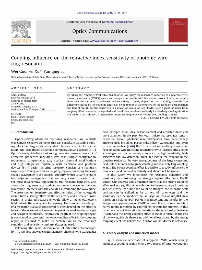
Fig. 1 shows a schematic of a typical PWRR which usuallyincludes a coupling region where two pieces of wire waveguides
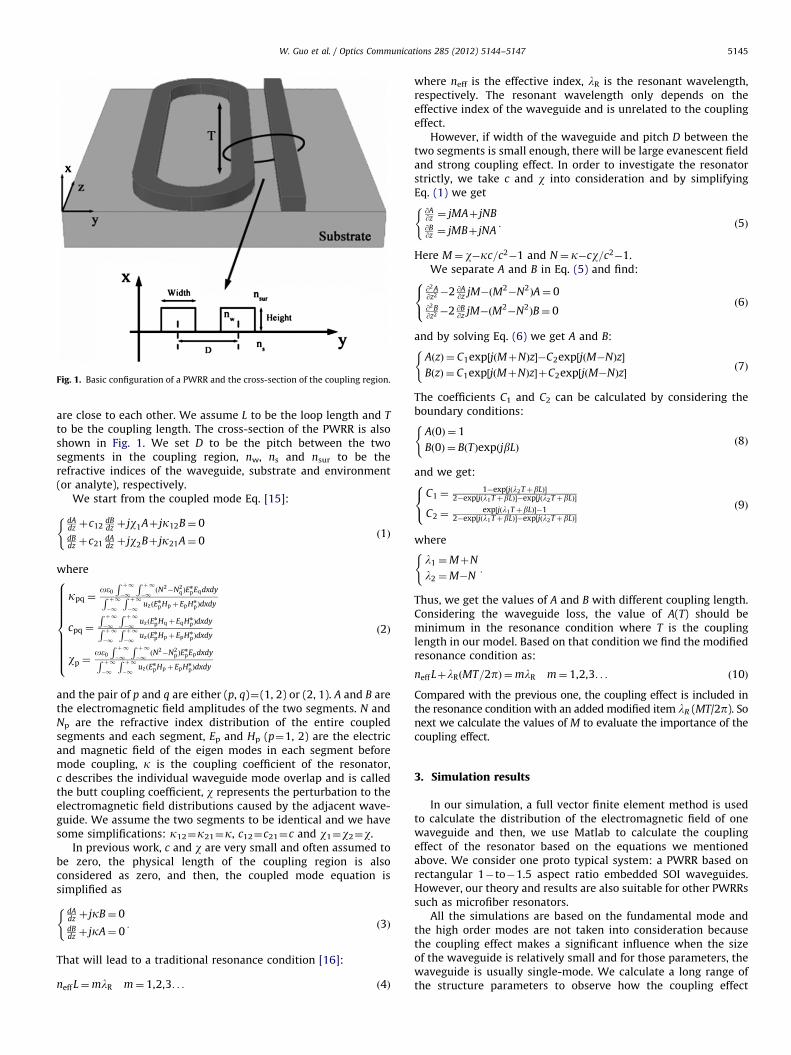
Fig. 1. Basic configuration of a PWRR and the cross-section of the coupling region.
W. Guo et al. / Optics Communications 285 (2012) 5144–5147 5145
are close to each other. We assume L to be the loop length and T
to be the coupling length. The cross-section of the PWRR is alsoshown in Fig. 1. We set D to be the pitch between the twosegments in the coupling region, nw, ns and nsur to be therefractive indices of the waveguide, substrate and environment(or analyte), respectively.
We start from the coupled mode Eq. [15]:
dAdz þc12
dBdz þ jw1Aþ jk12B¼ 0
dBdz þc21
dAdz þ jw2Bþ jk21A¼ 0
(ð1Þ
where
kpq ¼oe0
R þ1�1
R þ1�1ðN2�N2
qÞEn
pEqdxdyR þ1�1
R þ1�1
uzðEn
pHpþEpHn
pÞdxdy
cpq ¼
R þ1�1
R þ1�1
uzðEn
pHqþEqHn
pÞdxdyR þ1�1
R þ1�1
uzðEn
pHpþEpHn
pÞdxdy
wp ¼oe0
R þ1�1
R þ1�1ðN2�N2
pÞEn
pEpdxdyR þ1�1
R þ1�1
uzðEn
pHpþEpHn
pÞdxdy
8>>>>>>>>><>>>>>>>>>:
ð2Þ
and the pair of p and q are either (p, q)¼(1, 2) or (2, 1). A and B arethe electromagnetic field amplitudes of the two segments. N andNp are the refractive index distribution of the entire coupledsegments and each segment, Ep and Hp (p¼1, 2) are the electricand magnetic field of the eigen modes in each segment beforemode coupling, k is the coupling coefficient of the resonator,c describes the individual waveguide mode overlap and is calledthe butt coupling coefficient, w represents the perturbation to theelectromagnetic field distributions caused by the adjacent wave-guide. We assume the two segments to be identical and we havesome simplifications: k12¼k21¼k, c12¼c21¼c and w1¼w2¼w.
In previous work, c and w are very small and often assumed tobe zero, the physical length of the coupling region is alsoconsidered as zero, and then, the coupled mode equation issimplified as
dAdz þ jkB¼ 0dBdz þ jkA¼ 0
:
(ð3Þ
That will lead to a traditional resonance condition [16]:
neff L¼mlR m¼ 1,2,3. . . ð4Þ
where neff is the effective index, lR is the resonant wavelength,respectively. The resonant wavelength only depends on theeffective index of the waveguide and is unrelated to the couplingeffect.
However, if width of the waveguide and pitch D between thetwo segments is small enough, there will be large evanescent fieldand strong coupling effect. In order to investigate the resonatorstrictly, we take c and w into consideration and by simplifyingEq. (1) we get
@A@z ¼ jMAþ jNB@B@z ¼ jMBþ jNA
:
(ð5Þ
Here M¼ w�kc=c2�1 and N¼ k�cw=c2�1.We separate A and B in Eq. (5) and find:
@2A@z2 �2 @A
@z jM�ðM2�N2ÞA¼ 0
@2B@z2 �2 @B
@z jM�ðM2�N2ÞB¼ 0
8<: ð6Þ
and by solving Eq. (6) we get A and B:
AðzÞ ¼ C1exp½jðMþNÞz��C2exp½jðM�NÞz�
BðzÞ ¼ C1exp½jðMþNÞz�þC2exp½jðM�NÞz�
(ð7Þ
The coefficients C1 and C2 can be calculated by considering theboundary conditions:
Að0Þ ¼ 1
Bð0Þ ¼ BðTÞexpðjbLÞ
(ð8Þ
and we get:
C1 ¼1�exp½jðl2TþbLÞ�
2�exp½jðl1TþbLÞ��exp½jðl2TþbLÞ�
C2 ¼exp½jðl1TþbLÞ��1
2�exp½jðl1TþbLÞ��exp½jðl2TþbLÞ�
8<: ð9Þ
where
l1 ¼MþN
l2 ¼M�N:
(
Thus, we get the values of A and B with different coupling length.Considering the waveguide loss, the value of A(T) should beminimum in the resonance condition where T is the couplinglength in our model. Based on that condition we find the modifiedresonance condition as:
neff LþlRðMT=2pÞ ¼mlR m¼ 1,2,3. . . ð10Þ
Compared with the previous one, the coupling effect is included inthe resonance condition with an added modified item lR (MT/2p). Sonext we calculate the values of M to evaluate the importance of thecoupling effect.
3. Simulation results
In our simulation, a full vector finite element method is usedto calculate the distribution of the electromagnetic field of onewaveguide and then, we use Matlab to calculate the couplingeffect of the resonator based on the equations we mentionedabove. We consider one proto typical system: a PWRR based onrectangular 1�to�1.5 aspect ratio embedded SOI waveguides.However, our theory and results are also suitable for other PWRRssuch as microfiber resonators.
All the simulations are based on the fundamental mode andthe high order modes are not taken into consideration becausethe coupling effect makes a significant influence when the sizeof the waveguide is relatively small and for those parameters, thewaveguide is usually single-mode. We calculate a long range ofthe structure parameters to observe how the coupling effect
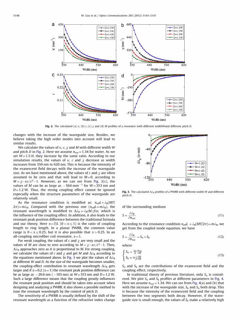
Fig. 2. The calculated (a) k, (b) c, (c) w and (d) M profiles of a resonator with different widthWand different pitch D.
Fig. 3. The calculated DlR profiles of a PWRR with different width W and different
pitch D.
W. Guo et al. / Optics Communications 285 (2012) 5144–51475146
changes with the increase of the waveguide size. Besides, webelieve taking the high order modes into account will lead tosimilar results.
We calculate the values of k, c, w and M with different width W
and pitch D in Fig. 2. Here we assume nsur¼1.34 for water. As weset W¼1.5 H, they increase by the same ratio. According to oursimulation results, the values of k, c and w decrease as widthincreases from 350 nm to 620 nm. This is because the intensity ofthe evanescent field decays with the increase of the waveguidesize. As we have mentioned above, the values of c and w are oftenassumed to be zero and that will lead to M¼0, according toM¼ w�kc=c2�1. However, as we can see from Fig. 2(c), thevalues of M can be as large as �564 mm�1 for W¼353 nm andD¼1.2 W. Thus, the strong coupling effect cannot be ignoredespecially when the structure parameters of the waveguide arerelatively small.
As the resonance condition is modified as: neffLþlR(MT/2p)¼mlR. Compared with the previous one (neffL¼mlR), theresonant wavelength is modified to DlR ¼ lRðM=bÞa, which isthe influence of the coupling effect. In addition, it also leads to theresonant peak position difference between the traditional formulaand our theory. Here a¼T/L (0oar1) is the ratio of couplinglength to ring length. In a planar PWRR, the common valuerange is 0oar0.25, but it is also possible that a40.25. In anall-coupling microfiber coil resonator, a¼1.
For weak coupling, the values of c and w are very small and thevalues of M are close to zero according to M¼ w�kc=c2�1. Then,DlR approaches zero as it is proportional to M. For strong coupling,we calculate the values of c and w and get M and DlR according tothe equations mentioned above. In Fig. 3 we plot the values of DlR
at different W and D. As the size of the waveguide becomes smaller,the coupling-effect contribution to resonant wavelength DlR getslarger and if a¼0.2 (a¼1) the resonant peak position difference canbe as large as �20.6 nm (�103 nm) at W¼353 nm and D¼1.2 W.Such a large difference means that the coupling greatly influencesthe resonant peak position and should be taken into account whendesigning and analyzing a PWRR. It also shows a possible method totune the resonant wavelength by the control of pitch D.
The sensitivity of a PWRR is usually defined by the shift of theresonant wavelength as a function of the refractive index change
of the surrounding medium
S¼@lR
@nsurð11Þ
According to the resonance condition neffL þlR(MT/2p)¼mlR, weget from the coupled mode equation, we have
S¼@lR
@nsur¼ SnþSk ð12Þ
where
Sn ¼2pb@neff@nE
Sk ¼ a lb@M@nE
8<: ð13Þ
Sn and Sk are the contributions of the evanescent field and thecoupling effect, respectively.
In traditional theory of previous literature, only Sn is consid-ered. We plot Sn and Sk profiles at different parameters in Fig. 4.Here we assume nsur¼1.34. We can see from Fig. 4(a) and (b) thatwith the increase of the waveguide size, Sk and Sn both drop. Thisis because the intensity of the evanescent field and the couplingbetween the two segments both decay. However, if the wave-guide size is small enough, the values of Sk make a relatively high
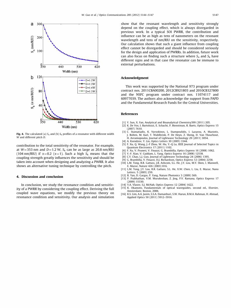
Fig. 4. The calculated (a) Sn and (b) Sk profiles of a resonator with different width
W and different pitch D.
W. Guo et al. / Optics Communications 285 (2012) 5144–5147 5147
contribution to the total sensitivity of the resonator. For example,at W¼353 nm and D¼1.2 W, Sk can be as large as 20.8 nm/RIU(104 nm/RIU) if a¼0.2 (a¼1). Such a high Sk means that thecoupling strength greatly influences the sensitivity and should betaken into account when designing and analyzing a PWRR. It alsoshows an alternative tuning technique by controlling the pitch.
4. Discussion and conclusion
In conclusion, we study the resonance condition and sensitiv-ity of a PWRR by considering the coupling effect. Deriving the fullcoupled wave equations, we modify the previous theory onresonance condition and sensitivity. Our analysis and simulation
show that the resonant wavelength and sensitivity stronglydepend on the coupling effect, which is always disregarded inprevious work. In a typical SOI PWRR, the contribution andinfluence can be as high as tens of nanometers on the resonantwavelength and tens of nm/RIU on the sensitivity, respectively.Our calculation shows that such a giant influence from couplingeffect cannot be disregarded and should be considered seriouslyfor the design and application of PWRRs. In addition, future workcan also focus on finding such a structure where Sn and Sk havedifferent signs and in that case the resonator can be immune toexternal perturbations.
Acknowledgment
This work was supported by the National 973 program undercontract nos. 2011CBA00200, 2012CB921803 and 2010CB327800and the NSFC program under contract nos. 11074117 and60977039. The authors also acknowledge the support from PAPDand the Fundamental Research Funds for the Central Universities.
References
[1] Y. Sun, X. Fan, Analytical and Bioanalytical Chemistry399 (2011) 205.[2] K. De Vos, I. Bartolozzi, E. Schacht, P. Bienstman, R. Baets, Optics Express 15
(2007) 7610.[3] C. Stamatiadis, K. Vyrsokinos, L. Stampoulidis, I. Lazarou, A. Maziotis,
J. Bolten, M. Karl, T. Wahlbrink, P. De Heyn, Z. Sheng, D. Van Thourhout,H. Avramopoulos, Journal of Lightwave Technology 29 (2011) 3054.
[4] A. Ksendzov, Y. Lin, Optics Letters 30 (2005) 3344.[5] F. Xu, Q. Wang, J.-F Zhou, W. Hu, Y.-Q Lu, IEEE Journal of Selected Topics in
Quantum Electronics 17 (2011) 1102.[6] F. Xu, V. Pruneri, V. Finazzi, G. Brambilla, Optics Express 16 (2008) 1062.[7] Y.-F. Xiao, V. Gaddam, L. Yang, Optics Express 16 (2008) 12538.[8] C.Y. Chao, L.J. Guo, Journal of Lightwave Technology 24 (2006) 1395.[9] G. Brambilla, V. Finazzi, D.J. Richardson, Optics Express 12 (2004) 2258.
[10] L.M. Tong, R.R. Gattass, J.B. Ashcom, S.L. He, J.Y. Lou, M.Y. Shen, I. Maxwell,E. Mazur, Nature 426 (2003) 816.
[11] L.M. Tong, J.Y. Lou, R.R. Gattass, S.L. He, X.W. Chen, L. Liu, E. Mazur, NanoLetters. 5 (2005) 259.
[12] R. Yan, D. Gargas, P. Yang, Nature Photonics 3 (2009) 569.[13] P. Prabhathan, V.M. Murukeshan, Z. Jing, P.V. Ramana, Optics Express 17
(2009) 15330.[14] Y.A. Vlasov, S.J. McNab, Optics Express 12 (2004) 1622.[15] K. Okamoto, Fundamentals of optical waveguides, second ed., Elsevier,
Amsterdam; Boston, 2006.[16] K.S. Lim, A.A. Jasim, S.S.A. Damanhuri, S.W. Harun, B.M.A. Rahman, H. Ahmad,
Applied Optics 50 (2011) 5912–5916.


![arXiv:1901.07267v2 [quant-ph] 27 Mar 2019 · Observation and stabilization of photonic Fock states in a hot radio-frequency resonator Mario F. Gely,1 Marios Kounalakis,1 Christian](https://img.pdfslide.net/doc/110x75/5f5a219b255f900a2c6ff142/arxiv190107267v2-quant-ph-27-mar-2019-observation-and-stabilization-of-photonic.jpg)