Embed Size (px)
Citation preview
Course Title: Electronics I School to Offer Course: Carlin, Elko, Jackpot, Owyhee, Spring Creek and West Wendover Grade Level: 9-12 District Textbook Adoption: Digital Techniques Student ISBN: 0-87119-221-7 Student Workbook: 0-87119-222-5 Laser Technology Student ISBN: 0-87119-114-8 Student Workbook: 0-87119-115-6 8-Bit Microprocessors Interfacing 6811 Student ISBN: 0-87119-166-0 Student Workbook: 0-87119-167-9
COURSE DESCRIPTION ELKO COUNTY SCHOOL DISTRICT
ELECTRONICS III ELE003
This year long course is designed to introduce the student to an advanced study of Electronics. The student will go more in depth into digital electronics and learn about semiconductor logic gates, flip-flops, counters, shift registers, clocks and one-shots, decoders and encoders, multiplexers, digital-to-analog and analog-to-digital conversion, semiconductor memories, and perform some actual digital troubleshooting. The student will then study 8-Bit Microprocessing and its interfacing and applications. In this course the 6840 Programmable Timer Module will be studied. This module will be interfaced to digital-to-analog and analog-to-digital conversion circuits as well as voltage-frequency converter circuits. The student will also construct microprocessor-controlled thermal, light, linear position sensing, linear and velocity sensing, and how stepper motors are controlled. The final course in this year of study will be Laser Technology. The students will learn about the characteristics of laser light, the laser as a light source, laser design, laser accessories, laser applications, and laser safety by performing measurements using an actual laser and accessories. Optional portions of the course will be printed circuit board construction in which the student will actually design and build a circuit board from scratch. Robotics will introduce the student to the basic programming, operation, and troubleshooting of a robot that moves, talks, and can retrieve items with its arm. Textbook Adoption: (OPTIONAL) – Heathkit – Printed Circuit Boards Text (OPTIONAL) – Heathkit – Robotics and Industrial Electronics Texts and Student Workbook Equipment Used: Heathkit – ETW-3700 Digital Trainer
Heathkit - ETW-3800 8-Bit Microprocessor Trainer with ETC-6811 and Programming Module Heathkit – ET-4200 Laser Trainer and Receiver Real-Time, Two-Channel Oscilloscope Digital Multimeter Logic Probe Soldering Iron, Solder, and Desoldering Pump (OPTIONAL) – Dremel drill and press (OPTIONAL) – Etchant Tank (OPTIONAL) – ET-18 HERO Robotics Trainer

ELECTRONICS III ELE003
(Page 1 of 1) When the student has completed this course, he or she will be able to: Standard Course Competencies
Digital Techniques General Course Objectives
10.1.1.3 10.1.1.5
1. Discuss the advantages and benefits of using digital techniques in electronic equipment.
10.1.1.3 10.1.1.5
2. Name the major applications of digital techniques in electronics.
10.1.1.3 3. Convert between decimal, binary, binary-coded decimal (BCD), and hexadecimal number systems.
10.1.1.3 10.1.1.5
4. Name the major components used in implementing digital circuits and explain how they operate.
10.1.1.3 10.1.1.5
5. Explain the operation of digital logic gates.
10.1.1.3 10.1.1.5
6. Identify the more commonly used integrated circuit families used in digital equipment and discuss their operation, characteristics, and features.
10.1.1.3 10.1.1.5
7. Use Boolean algebra to express logic operations and minimize logic circuits in design.
10.1.1.3 10.1.1.5
8. Explain the operation of flip-flops.
10.1.1.3 10.1.1.5
9. Discuss the operation and application of binary and BCD counters, shift registers, and sequential logic circuits.
10.1.1.3 10.1.1.5
10. Name the most frequently used combinational logic circuits and explain their operation.
10.1.1.3 10.1.1.5
11. Discuss the operation and application of digital counters in time and frequency measurements.
10.1.1.3 10.1.1.5
12. Explain how a digital computer is organized and how it operates.
10.1.1.2 10.1.1.3 10.1.1.5
13. Construct and test logic circuits using digital techniques.

ELECTRONICS II ELE002
(Page 1 of 2) When the student has completed this course, he or she will be able to: Standard Course Competencies
8 Bit Microprocessor Interfacing and Applications General Course Objectives
10.1.1.3 10.1.1.5
14. Describe the operating characteristics of a Programmable Timer Module (PTM).
10.1.1.2 10.1.1.3 10.1.1.5
15. Interface a PTM to a microcomputer system to generate timed intervals, output waveforms, and measure input waveforms.
10.1.1.2 10.1.1.3 10.1.1.5
16. Interface digital-to-analog and anolog-to-digital converters to a microprocessor system
10.1.1.2 10.1.1.3 10.1.1.5
17. Construct a microprocessor-controlled digital multimeter, or DMM.
10.1.1.3 10.1.1.5
18. Describe the component requirements of data acquisition and process control systems.
10.1.1.3 10.1.1.5
19. Compare the operating characteristics of the following temperature sensors: RTDs, thermistors, semiconductor junctions, solid state temperature sensors, bimetallic strips and discs, and mercury columns.
10.1.1.2 10.1.1.3 10.1.1.5
20. Construct a microprocessor-controlled thermometer.
10.1.1.3 10.1.1.5
21. Compare the operating characteristics of photoconductive, photovoltaic, and photoemissive optical sensing devices.
10.1.1.2 10.1.1.3 10.1.1.4
22. Construct a microprocessor-controlled light meter, or photometer.
10.1.1.2 10.1.1.3 10.1.1.5
23. Develop the software and hardware required to allow a microprocessor to measure the following mechanical phenomena: Linear and angular position, linear and angular velocity, linear and angular acceleration, force, pressure, flow, and level.
10.1.1.2 10.1.1.3 10.1.1.5
24. Explain the operation of Hall-effect devices and design a Hall-effect linear position and velocity measuring circuit.
10.1.1.3 10.1.1.5
25. Explain how strain gages are used with a microprocessor to measure force.
10.1.1.2 10.1.1.3 10.1.1.5
26. Design and construct a microprocessor/stepper motor interface and control circuit.
10.1.1.3 10.1.1.5
27. Describe a typical flexible manufacturing system, or FMS.
ELECTRONICS II ELE002
(Page 1 of 3) When the student has completed this course, he or she will be able to: Standard Course Competencies
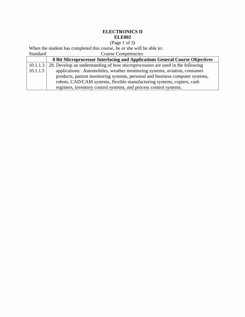
8 Bit Microprocessor Interfacing and Applications General Course Objectives 10.1.1.3 10.1.1.5
28. Develop an understanding of how microprocessors are used in the following applications: Automobiles, weather monitoring systems, aviation, consumer products, patient monitoring systems, personal and business computer systems, robots, CAD/CAM systems, flexible manufacturing systems, copiers, cash registers, inventory control systems, and process control systems.

ELECTRONICS II ELE002
(Page 1 of 4) When the student has completed this course, he or she will be able to: Standard Course Competencies
Laser Technology General Course Objectives 10.1.1.3 10.1.1.4 10.1.1.5
29. Define basic optical terms and concepts related to lasers.
10.1.1.3 10.1.1.4 10.1.1.5
30. Compare the characteristics of laser light with similar characteristics of “ordinary” light.
10.1.1.3 10.1.1.4 10.1.1.5
31. List the essential components of all laser light.
10.1.1.3 10.1.1.4 10.1.1.5
32. Explain the function of each laser component in relationship to laser operation.
10.1.1.3 10.1.1.4 10.1.1.5
33. Identify various types of common lasers by their output characteristics.
10.1.1.3 10.1.1.4 10.1.1.5
34. Match a type of laser to a given application.
10.1.1.3 10.1.1.4 10.1.1.5
35. Recognize safety hazards associated with different classifications of lasers.
10.1.1.3 10.1.1.4 10.1.1.5
36. Choose accessories to use with different lasers in a given application.
10.1.1.3 10.1.1.4 10.1.1.5
37. Calculate power density at the focal point of a lens if laser and optical parameters are given.
ELECTRONICS II ELE002
(Page 1 of 5) When the student has completed this course, he or she will be able to: Standard Course Competencies
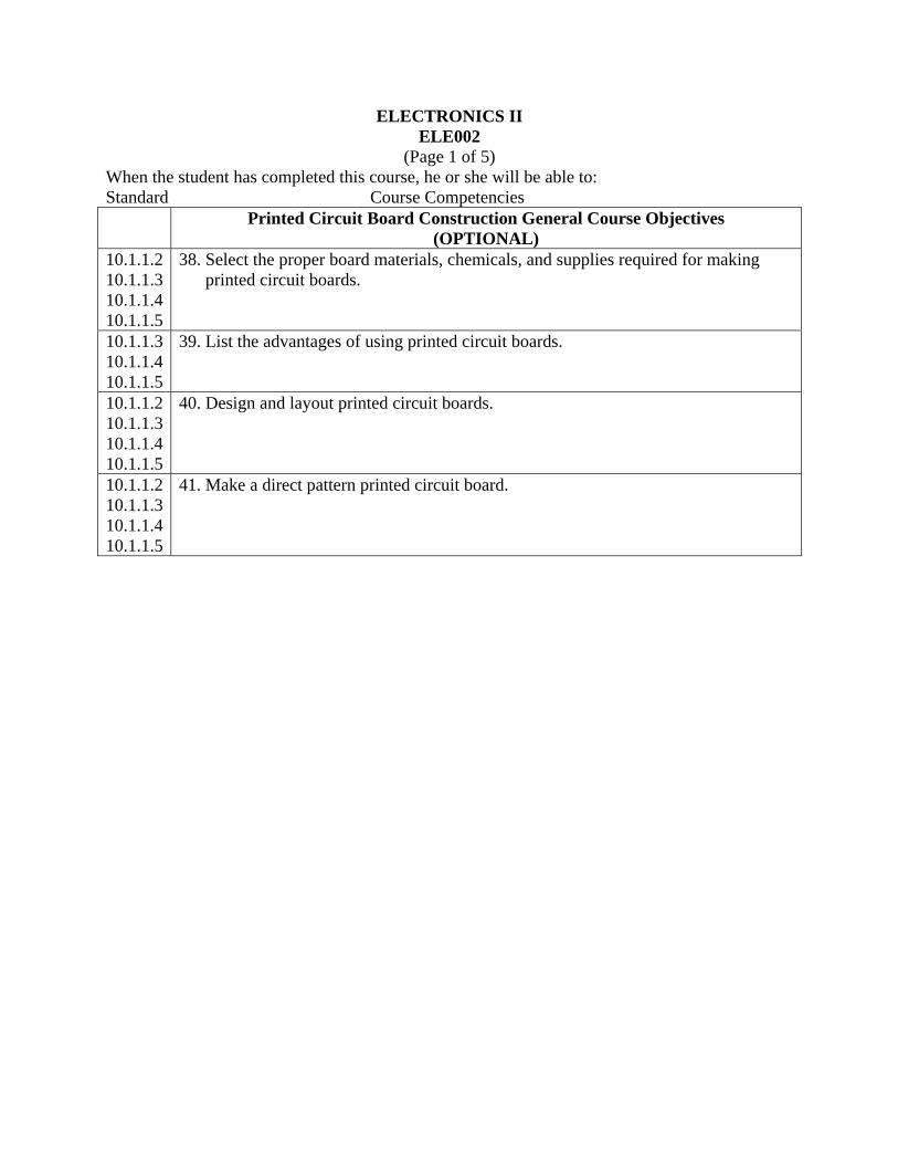
Printed Circuit Board Construction General Course Objectives (OPTIONAL)
10.1.1.2 10.1.1.3 10.1.1.4 10.1.1.5
38. Select the proper board materials, chemicals, and supplies required for making printed circuit boards.
10.1.1.3 10.1.1.4 10.1.1.5
39. List the advantages of using printed circuit boards.
10.1.1.2 10.1.1.3 10.1.1.4 10.1.1.5
40. Design and layout printed circuit boards.
10.1.1.2 10.1.1.3 10.1.1.4 10.1.1.5
41. Make a direct pattern printed circuit board.

ELECTRONICS II ELE002
(Page 1 of 6) When the student has completed this course, he or she will be able to: Standard Course Competencies
Robotics and Industrial Electronics General Course Objectives (OPTIONAL)
10.1.1.1 10.1.1.3 10.1.1.4 10.1.1.5
42. Demonstrate a working knowledge of the principles used in robotics.
10.1.1.1 10.1.1.3 10.1.1.4 10.1.1.5
43. Describe AC and Fluidic power.
10.1.1.1 10.1.1.3 10.1.1.4 10.1.1.5
44. Discuss the use of DC power and positioning.
10.1.1.1 10.1.1.2 10.1.1.3 10.1.1.4 10.1.1.5
45. Demonstrate the application of microprocessor fundamentals to programming robots.
10.1.1.1 10.1.1.3 10.1.1.4 10.1.1.5
46. Explain the typical microprocessor controller techniques used with the 6808 MPU.
10.1.1.1 10.1.1.3 10.1.1.4 10.1.1.5
47. Explain data acquisition, data handling, and conversion.
10.1.1.1 10.1.1.2 10.1.1.3 10.1.1.4 10.1.1.5
48. Demonstrate the different forms of voice synthesis.
10.1.1.1 10.1.1.2 10.1.1.3 10.1.1.4 10.1.1.5
49. Demonstrate interfacing the ET-18 HERO Robot Trainer peripheral devices such as RAM, ROM, and control circuits.

ELECTRONICS III ELE003
(Page 1 of 1) When the student has completed this course, he or she will be able to: Standard Course Competencies
Digital Techniques Specific Course Objectives
10.1.1.1 10.1.1.3 10.1.1.4 10.1.1.5
1. Given a list of physical variables, components, devices, and other items, classify them as being either analog or digital in nature.
10.1.1.1 10.1.1.3 10.1.1.4 10.1.1.5
2. List at least five advantages of digital techniques over analog systems.
10.1.1.3 10.1.1.5
3. List at least five examples of electronic equipment using digital techniques.
10.1.1.3 10.1.1.5
4. State the factors that have most influenced the growth of digital techniques.
10.1.1.3 10.1.1.5
5. Perform conversions between the decimal, binary, binary-coded decimal (BCD) and hexadecimal number systems.
10.1.1.3 10.1.1.5
6. Given a list of popular digital codes, read and identify them including pure binary, BCD, Gray, excess 3 and ASCII.
10.1.1.3 10.1.1.5
7. List two key ways binary data is represented with digital hardware.
10.1.1.3 10.1.1.5
8. List advantages and disadvantages of both serial and parallel methods of binary data transmission.
10.1.1.1 10.1.1.3 10.1.1.5
9. Name two types of semiconductor elements used in digital circuits and list two advantages and disadvantages of each.
10.1.1.1 10.1.1.3 10.1.1.5
10. Identify from a list of symbols used to represent PNP and NPN bipolar transistors and P and N channel enhancement mode MOSFETs, how they are used in a digital circuit.
10.1.1.1 10.1.1.3 10.1.1.5
11. Explain the operation of both bipolar transistors and MOSFETs.
10.1.1.1 10.1.1.3 10.1.1.5
12. Name and explain three operating modes of a bipolar transistor.
10.1.1.1 10.1.1.3 10.1.1.5
13. Explain the operation of a logic inverter circuit.
10.1.1.3 10.1.1.5
14. List the three basic types of logic elements.
ELECTRONICS III ELE003
(Page 1 of 2) When the student has completed this course, he or she will be able to: Standard Course Competencies
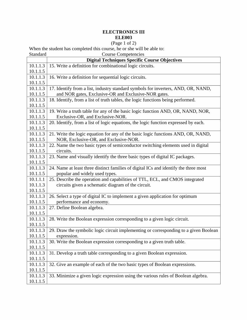
Digital Techniques Specific Course Objectives 10.1.1.3 10.1.1.5
15. Write a definition for combinational logic circuits.
10.1.1.3 10.1.1.5
16. Write a definition for sequential logic circuits.
10.1.1.3 10.1.1.5
17. Identify from a list, industry standard symbols for inverters, AND, OR, NAND, and NOR gates, Exclusive-OR and Exclusive-NOR gates.
10.1.1.3 10.1.1.5
18. Identify, from a list of truth tables, the logic functions being performed.
10.1.1.3 10.1.1.5
19. Write a truth table for any of the basic logic function AND, OR, NAND, NOR, Exclusive-OR, and Exclusive-NOR.
10.1.1.3 10.1.1.5
20. Identify, from a list of logic equations, the logic function expressed by each.
10.1.1.3 10.1.1.5
21. Write the logic equation for any of the basic logic functions AND, OR, NAND, NOR, Exclusive-OR, and Exclusive-NOR.
10.1.1.3 10.1.1.5
22. Name the two basic types of semiconductor switching elements used in digital circuits.
10.1.1.3 10.1.1.5
23. Name and visually identify the three basic types of digital IC packages.
10.1.1.3 10.1.1.5
24. Name at least three distinct families of digital ICs and identify the three most popular and widely used types.
10.1.1.1 10.1.1.3 10.1.1.5
25. Describe the operation and capabilities of TTL, ECL, and CMOS integrated circuits given a schematic diagram of the circuit.
10.1.1.3 10.1.1.5
26. Select a type of digital IC to implement a given application for optimum performance and economy.
10.1.1.3 10.1.1.5
27. Define Boolean algebra.
10.1.1.3 10.1.1.5
28. Write the Boolean expression corresponding to a given logic circuit.
10.1.1.3 10.1.1.5
29. Draw the symbolic logic circuit implementing or corresponding to a given Boolean expression.
10.1.1.3 10.1.1.5
30. Write the Boolean expression corresponding to a given truth table.
10.1.1.3 10.1.1.5
31. Develop a truth table corresponding to a given Boolean expression.
10.1.1.3 10.1.1.5
32. Give an example of each of the two basic types of Boolean expressions.
10.1.1.3 10.1.1.5
33. Minimize a given logic expression using the various rules of Boolean algebra.

ELECTRONICS III ELE003
(Page 1 of 3) When the student has completed this course, he or she will be able to: Standard Course Competencies
Digital Techniques Specific Course Objectives 10.1.1.2 10.1.1.3 10.1.1.5
34. Implement a given Boolean expression with either NAND or NOR gates.
10.1.1.3 10.1.1.5
35. Write the Boolean expression of logic circuits using the wired OR connection.
10.1.1.2 10.1.1.3 10.1.1.5
36. Properly connect the inputs and outputs of TTL and CMOS logic gates in typical applications.
10.1.1.3 10.1.1.5
37. Write a definition for a flip flop.
10.1.1.3 10.1.1.5
38. Name the three basic types of flip-flops.
10.1.1.3 10.1.1.5
39. Identify, from a logic diagram each of three types of flip-flops from their symbols or logic gate connections.
10.1.1.3 10.1.1.5
40. Draw the symbols and detailed logic diagrams of the RS, D, and JK flip-flops.
10.1.1.3 10.1.1.5
41. Fill in the appropriate output states for the RS, D, or JK flip-flop showing all possible conditions, from a truth table for each.
10.1.1.3 10.1.1.5
42. Draw, from a set of input waveforms for the RS, D, or JK flip-flops, the corresponding output waveform.
10.1.1.3 10.1.1.5
43. Give a practical application for each of the three types of flip-flops.
10.1.1.3 10.1.1.5
44. Write a definition for a register.
10.1.1.2 10.1.1.3 10.1.1.5
45. Measure the output states and determine the binary number stored there from a register made with any type of flip-flop.
10.1.1.3 10.1.1.5
46. Name the two most widely used types of sequential logic circuits.
10.1.1.3 10.1.1.5
47. Explain the operation of both binary and BCD counters.
10.1.1.3 10.1.1.5
48. Determine the maximum count capability of a binary or BCD counter given the number of flip-flops it contains and a logic diagram.
10.1.1.3 10.1.1.5
49. Determine the count sequence of a counter from a logic diagram and draw the circuit waveform.
10.1.1.3 10.1.1.5
50. Explain the operation of a shift register.
10.1.1.3 10.1.1.4
51. List four applications for shift registers.
ELECTRONICS III ELE003
(Page 1 of 4) When the student has completed this course, he or she will be able to: Standard Course Competencies
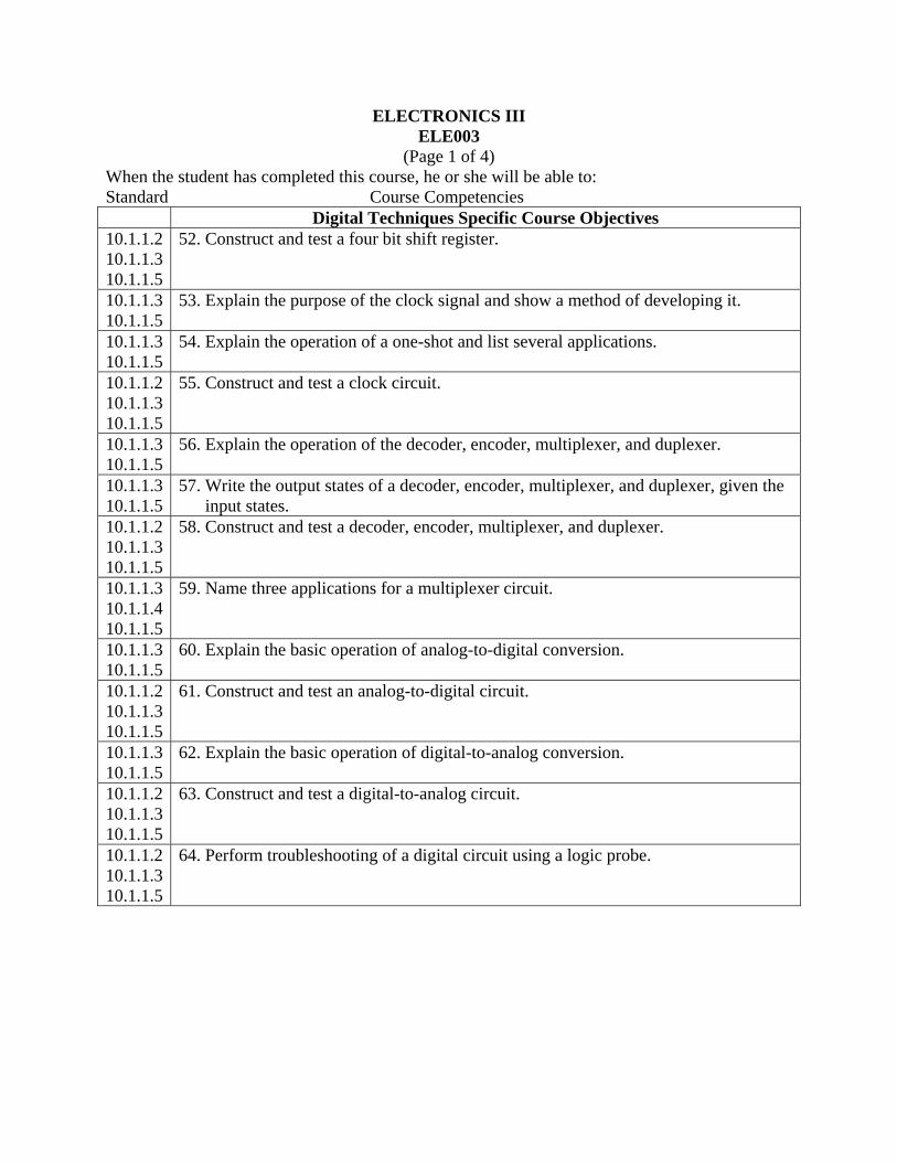
Digital Techniques Specific Course Objectives 10.1.1.2 10.1.1.3 10.1.1.5
52. Construct and test a four bit shift register.
10.1.1.3 10.1.1.5
53. Explain the purpose of the clock signal and show a method of developing it.
10.1.1.3 10.1.1.5
54. Explain the operation of a one-shot and list several applications.
10.1.1.2 10.1.1.3 10.1.1.5
55. Construct and test a clock circuit.
10.1.1.3 10.1.1.5
56. Explain the operation of the decoder, encoder, multiplexer, and duplexer.
10.1.1.3 10.1.1.5
57. Write the output states of a decoder, encoder, multiplexer, and duplexer, given the input states.
10.1.1.2 10.1.1.3 10.1.1.5
58. Construct and test a decoder, encoder, multiplexer, and duplexer.
10.1.1.3 10.1.1.4 10.1.1.5
59. Name three applications for a multiplexer circuit.
10.1.1.3 10.1.1.5
60. Explain the basic operation of analog-to-digital conversion.
10.1.1.2 10.1.1.3 10.1.1.5
61. Construct and test an analog-to-digital circuit.
10.1.1.3 10.1.1.5
62. Explain the basic operation of digital-to-analog conversion.
10.1.1.2 10.1.1.3 10.1.1.5
63. Construct and test a digital-to-analog circuit.
10.1.1.2 10.1.1.3 10.1.1.5
64. Perform troubleshooting of a digital circuit using a logic probe.
ELECTRONICS III ELE003
(Page 1 of 5) When the student has completed this course, he or she will be able to: Standard Course Competencies
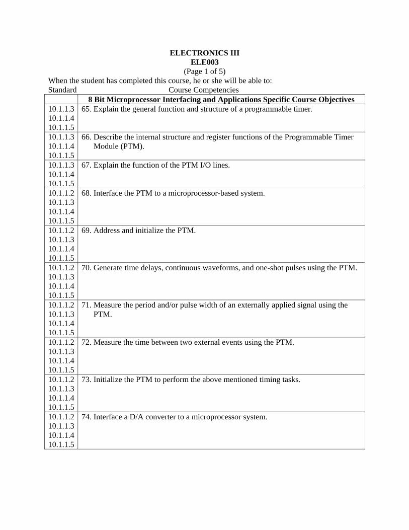
8 Bit Microprocessor Interfacing and Applications Specific Course Objectives 10.1.1.3 10.1.1.4 10.1.1.5
65. Explain the general function and structure of a programmable timer.
10.1.1.3 10.1.1.4 10.1.1.5
66. Describe the internal structure and register functions of the Programmable Timer Module (PTM).
10.1.1.3 10.1.1.4 10.1.1.5
67. Explain the function of the PTM I/O lines.
10.1.1.2 10.1.1.3 10.1.1.4 10.1.1.5
68. Interface the PTM to a microprocessor-based system.
10.1.1.2 10.1.1.3 10.1.1.4 10.1.1.5
69. Address and initialize the PTM.
10.1.1.2 10.1.1.3 10.1.1.4 10.1.1.5
70. Generate time delays, continuous waveforms, and one-shot pulses using the PTM.
10.1.1.2 10.1.1.3 10.1.1.4 10.1.1.5
71. Measure the period and/or pulse width of an externally applied signal using the PTM.
10.1.1.2 10.1.1.3 10.1.1.4 10.1.1.5
72. Measure the time between two external events using the PTM.
10.1.1.2 10.1.1.3 10.1.1.4 10.1.1.5
73. Initialize the PTM to perform the above mentioned timing tasks.
10.1.1.2 10.1.1.3 10.1.1.4 10.1.1.5
74. Interface a D/A converter to a microprocessor system.

ELECTRONICS III ELE003
(Page 1 of 6) When the student has completed this course, he or she will be able to: Standard Course Competencies
8 Bit Microprocessor Interfacing and Applications Specific Course Objectives 10.1.1.2 10.1.1.3 10.1.1.4 10.1.1.5
75. Write programs to generate waveforms from a microprocessor controlled D/A converter circuit.
10.1.1.3 10.1.1.4 10.1.1.5
76. Describe how a multiplying D/A converter circuit can be used to amplify or attenuate analog signals under control of a microprocessor.
10.1.1.3 10.1.1.4 10.1.1.5
77. Describe how D/A converters are used to control the direction of rotation, speed, and position of DC motors.
10.1.1.2 10.1.1.3 10.1.1.4 10.1.1.5
78. Interface parallel output A/D converters and V/F converters to a microprocessor via a PIA.
10.1.1.3 10.1.1.4 10.1.1.5
79. Describe how a PIA is used to provide handshake control of the analog conversion process of a parallel output A/D converter.
10.1.1.2 10.1.1.3 10.1.1.4 10.1.1.5
80. Write a program to count pulses generated by a V/F converter.
10.1.1.3 10.1.1.4 10.1.1.5
81. Describe the circuit requirements of a typical data acquisition system.
10.1.1.3 10.1.1.4 10.1.1.5
82. Describe how sample/hold (S/H) devices and analog multiplexers are used with A/D converters in a data acquisition system.
10.1.1.3 10.1.1.4 10.1.1.5
83. Describe and provide an example of a microprocessor-based industrial control system.
10.1.1.1 10.1.1.3 10.1.1.4 10.1.1.5
84. Explain the operating principles of RTD, thermistor, thermocouple, and semiconductor type temperature sensors and transducers.
10.1.1.1 10.1.1.2 10.1.1.3 10.1.1.4 10.1.1.5
85. Construct a microprocessor-controlled thermometer.
ELECTRONICS III ELE003
(Page 1 of 7) When the student has completed this course, he or she will be able to: Standard Course Competencies
8 Bit Microprocessor Interfacing and Applications Specific Course Objectives 10.1.1.1 10.1.1.3 10.1.1.4 10.1.1.5
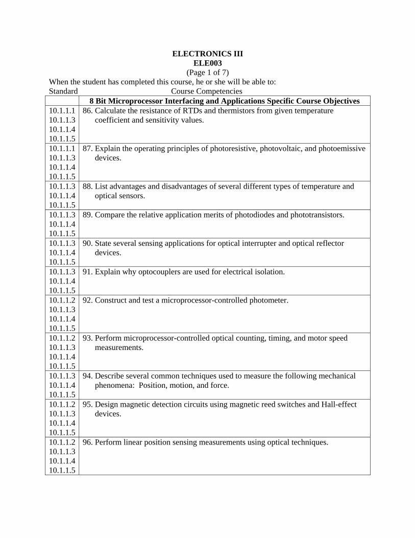
86. Calculate the resistance of RTDs and thermistors from given temperature coefficient and sensitivity values.
10.1.1.1 10.1.1.3 10.1.1.4 10.1.1.5
87. Explain the operating principles of photoresistive, photovoltaic, and photoemissive devices.
10.1.1.3 10.1.1.4 10.1.1.5
88. List advantages and disadvantages of several different types of temperature and optical sensors.
10.1.1.3 10.1.1.4 10.1.1.5
89. Compare the relative application merits of photodiodes and phototransistors.
10.1.1.3 10.1.1.4 10.1.1.5
90. State several sensing applications for optical interrupter and optical reflector devices.
10.1.1.3 10.1.1.4 10.1.1.5
91. Explain why optocouplers are used for electrical isolation.
10.1.1.2 10.1.1.3 10.1.1.4 10.1.1.5
92. Construct and test a microprocessor-controlled photometer.
10.1.1.2 10.1.1.3 10.1.1.4 10.1.1.5
93. Perform microprocessor-controlled optical counting, timing, and motor speed measurements.
10.1.1.3 10.1.1.4 10.1.1.5
94. Describe several common techniques used to measure the following mechanical phenomena: Position, motion, and force.
10.1.1.2 10.1.1.3 10.1.1.4 10.1.1.5
95. Design magnetic detection circuits using magnetic reed switches and Hall-effect devices.
10.1.1.2 10.1.1.3 10.1.1.4 10.1.1.5
96. Perform linear position sensing measurements using optical techniques.

ELECTRONICS III ELE003
(Page 1 of 8) When the student has completed this course, he or she will be able to: Standard Course Competencies
8 Bit Microprocessor Interfacing and Applications Specific Course Objectives 10.1.1.2 10.1.1.3 10.1.1.4 10.1.1.5
97. Perform linear position and velocity sensing measurements using magnetic Hall-effect devices.
10.1.1.3 10.1.1.4 10.1.1.5
98. Define stress and strain.
10.1.1.3 10.1.1.4 10.1.1.5
99. State the three general types of stress/strain situations.
10.1.1.1 10.1.1.3 10.1.1.4 10.1.1.5
100. Explain how resistive strain gages are used to measure force.
10.1.1.1 10.1.1.3 10.1.1.4 10.1.1.5
101. Define and calculate the gage factor for a resistive strain gage.
10.1.1.3 10.1.1.4 10.1.1.5
102. State several microprocessor control applications for simple control devices.
10.1.1.1 10.1.1.3 10.1.1.4 10.1.1.5
103. Explain how a microprocessor can control the effective current to a load using and SCR or TRIAC.
10.1.1.3 10.1.1.4 10.1.1.5
104. State the advantages of using an opto-isolator in a microprocessor control circuit.
10.1.1.1 10.1.1.3 10.1.1.4 10.1.1.5
105. List at least three considerations that must be taken into account when you are using solid state relays to control high current loads.
10.1.1.3 10.1.1.4 10.1.1.5
106. Explain how to control the speed of the various types of motors.
10.1.1.1 10.1.1.3 10.1.1.4 10.1.1.5
107. Describe the operation of bipolar and unipolar stepper motors.

ELECTRONICS III ELE003
(Page 1 of 9) When the student has completed this course, he or she will be able to: Standard Course Competencies
8 Bit Microprocessor Interfacing and Applications Specific Course Objectives 10.1.1.3 10.1.1.4 10.1.1.5
108. Explain how to control the direction of rotation, amount of rotation, and speed of a stepper motor.
10.1.1.3 10.1.1.4 10.1.1.5
109. Explain a microprocessor/stepper motor interface and control circuit.
10.1.1.2 10.1.1.3 10.1.1.4 10.1.1.5
110. Interface and demonstrate control of a stepper motor with a microprocessor.
10.1.1.3 10.1.1.4 10.1.1.5
111. Explain how the use of a microprocessor applies to the following: Automobiles, robots, hospital care, aviation, and business and industry.

ELECTRONICS III ELE003
(Page 1 of 10) When the student has completed this course, he or she will be able to: Standard Course Competencies
Laser Technology Specific Course Objectives 10.1.1.3 10.1.1.4 10.1.1.5
112. Describe the major characteristics of light.
10.1.1.3 10.1.1.4 10.1.1.5
113. Determine the frequency of a light wave when the wavelength is known.
10.1.1.3 10.1.1.4 10.1.1.5
114. List three characteristics of laser light.
10.1.1.3 10.1.1.4 10.1.1.5
115. Explain the Inverse Square Law.
10.1.1.3 10.1.1.4 10.1.1.5
116. Explain the difference between radiometric and photometric systems of light measurements.
10.1.1.3 10.1.1.4 10.1.1.5
117. Define the following characteristics of light waves: Amplitude, period, frequency wavelength, interference, and diffraction.
10.1.1.3 10.1.1.4 10.1.1.5
118. Explain or calculate values for the radiometric quantities: Energy, power, irradiance, excitance, intensity, and radiance.
10.1.1.2 10.1.1.3 10.1.1.4 10.1.1.5
119. Perform radiometric light measurements with a Helium-Neon laser.
10.1.1.2 10.1.1.3 10.1.1.4 10.1.1.5
120. Perform irradiance, diffraction, interference, and beam diameter measurements with a Helium-Neon laser.
10.1.1.3 10.1.1.4 10.1.1.5
121. Explain the physics of light generation.
10.1.1.3 10.1.1.4 10.1.1.5
122. List the four essential components of any laser.
10.1.1.3 10.1.1.4 10.1.1.5
123. Explain the function of the four essential components of any laser.
ELECTRONICS III ELE003
(Page 1 of 11) When the student has completed this course, he or she will be able to: Standard Course Competencies
Laser Technology Specific Course Objectives 10.1.1.3 10.1.1.4 10.1.1.5
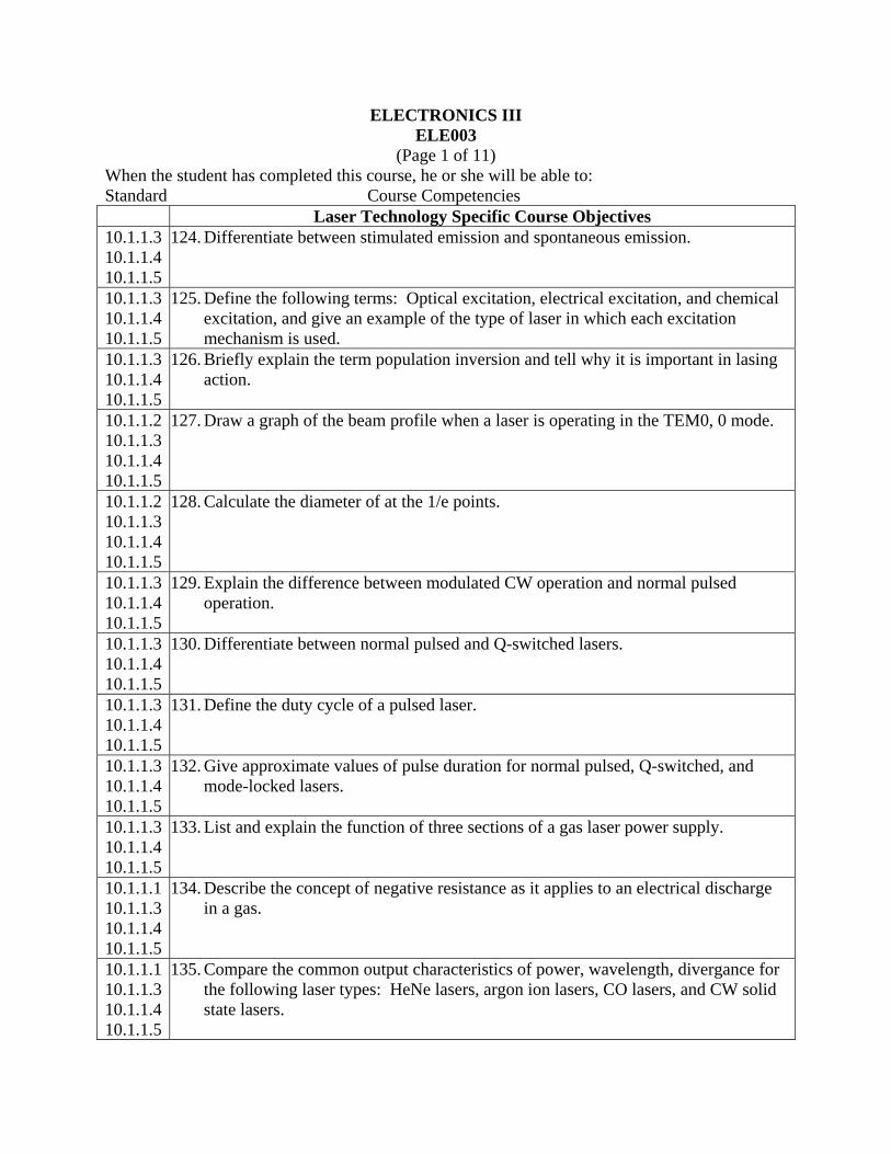
124. Differentiate between stimulated emission and spontaneous emission.
10.1.1.3 10.1.1.4 10.1.1.5
125. Define the following terms: Optical excitation, electrical excitation, and chemical excitation, and give an example of the type of laser in which each excitation mechanism is used.
10.1.1.3 10.1.1.4 10.1.1.5
126. Briefly explain the term population inversion and tell why it is important in lasing action.
10.1.1.2 10.1.1.3 10.1.1.4 10.1.1.5
127. Draw a graph of the beam profile when a laser is operating in the TEM0, 0 mode.
10.1.1.2 10.1.1.3 10.1.1.4 10.1.1.5
128. Calculate the diameter of at the 1/e points.
10.1.1.3 10.1.1.4 10.1.1.5
129. Explain the difference between modulated CW operation and normal pulsed operation.
10.1.1.3 10.1.1.4 10.1.1.5
130. Differentiate between normal pulsed and Q-switched lasers.
10.1.1.3 10.1.1.4 10.1.1.5
131. Define the duty cycle of a pulsed laser.
10.1.1.3 10.1.1.4 10.1.1.5
132. Give approximate values of pulse duration for normal pulsed, Q-switched, and mode-locked lasers.
10.1.1.3 10.1.1.4 10.1.1.5
133. List and explain the function of three sections of a gas laser power supply.
10.1.1.1 10.1.1.3 10.1.1.4 10.1.1.5
134. Describe the concept of negative resistance as it applies to an electrical discharge in a gas.
10.1.1.1 10.1.1.3 10.1.1.4 10.1.1.5
135. Compare the common output characteristics of power, wavelength, divergance for the following laser types: HeNe lasers, argon ion lasers, CO lasers, and CW solid state lasers.
ELECTRONICS III ELE003
(Page 1 of 12) When the student has completed this course, he or she will be able to: Standard Course Competencies
Laser Technology Specific Course Objectives 10.1.1.3 10.1.1.4 10.1.1.5
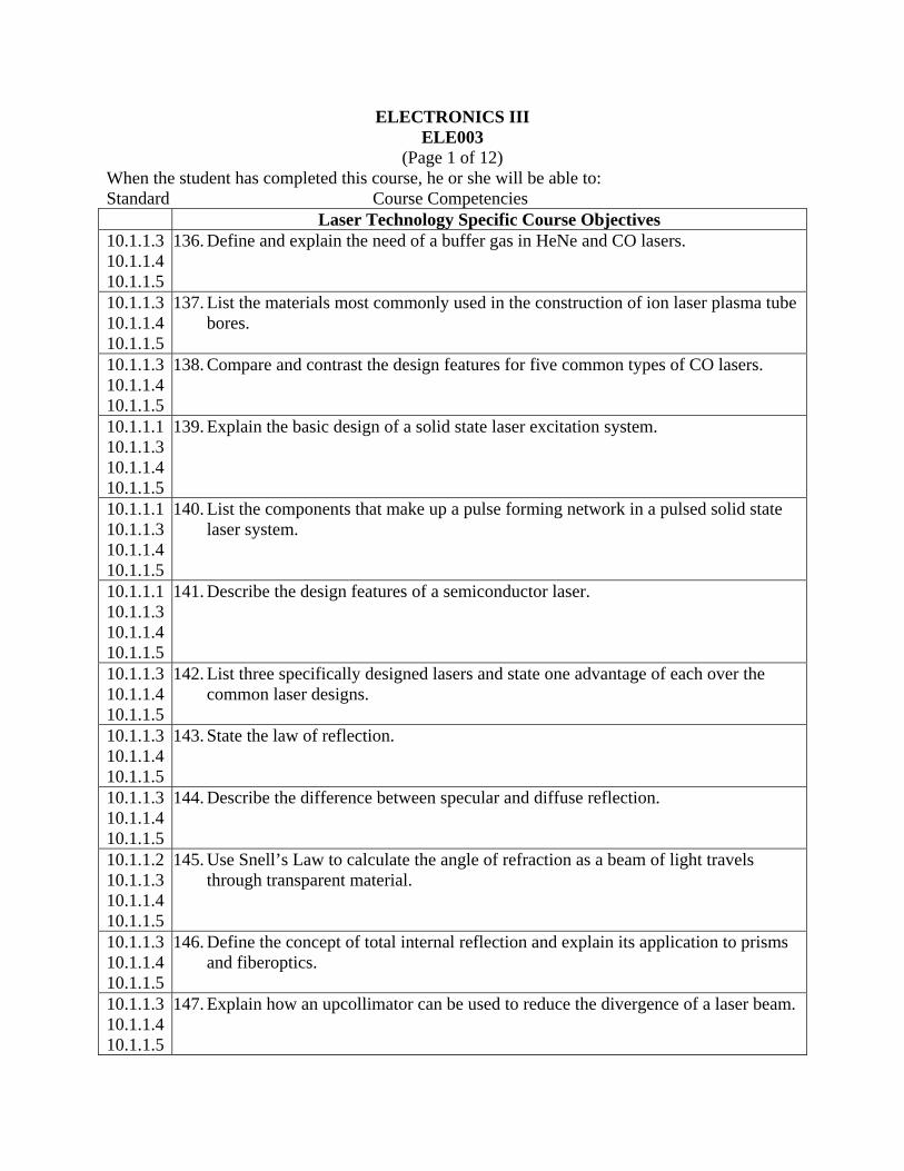
136. Define and explain the need of a buffer gas in HeNe and CO lasers.
10.1.1.3 10.1.1.4 10.1.1.5
137. List the materials most commonly used in the construction of ion laser plasma tube bores.
10.1.1.3 10.1.1.4 10.1.1.5
138. Compare and contrast the design features for five common types of CO lasers.
10.1.1.1 10.1.1.3 10.1.1.4 10.1.1.5
139. Explain the basic design of a solid state laser excitation system.
10.1.1.1 10.1.1.3 10.1.1.4 10.1.1.5
140. List the components that make up a pulse forming network in a pulsed solid state laser system.
10.1.1.1 10.1.1.3 10.1.1.4 10.1.1.5
141. Describe the design features of a semiconductor laser.
10.1.1.3 10.1.1.4 10.1.1.5
142. List three specifically designed lasers and state one advantage of each over the common laser designs.
10.1.1.3 10.1.1.4 10.1.1.5
143. State the law of reflection.
10.1.1.3 10.1.1.4 10.1.1.5
144. Describe the difference between specular and diffuse reflection.
10.1.1.2 10.1.1.3 10.1.1.4 10.1.1.5
145. Use Snell’s Law to calculate the angle of refraction as a beam of light travels through transparent material.
10.1.1.3 10.1.1.4 10.1.1.5
146. Define the concept of total internal reflection and explain its application to prisms and fiberoptics.
10.1.1.3 10.1.1.4 10.1.1.5
147. Explain how an upcollimator can be used to reduce the divergence of a laser beam.
ELECTRONICS III ELE003
(Page 1 of 13) When the student has completed this course, he or she will be able to: Standard Course Competencies
Laser Technology Specific Course Objectives 10.1.1.3 10.1.1.4 10.1.1.5
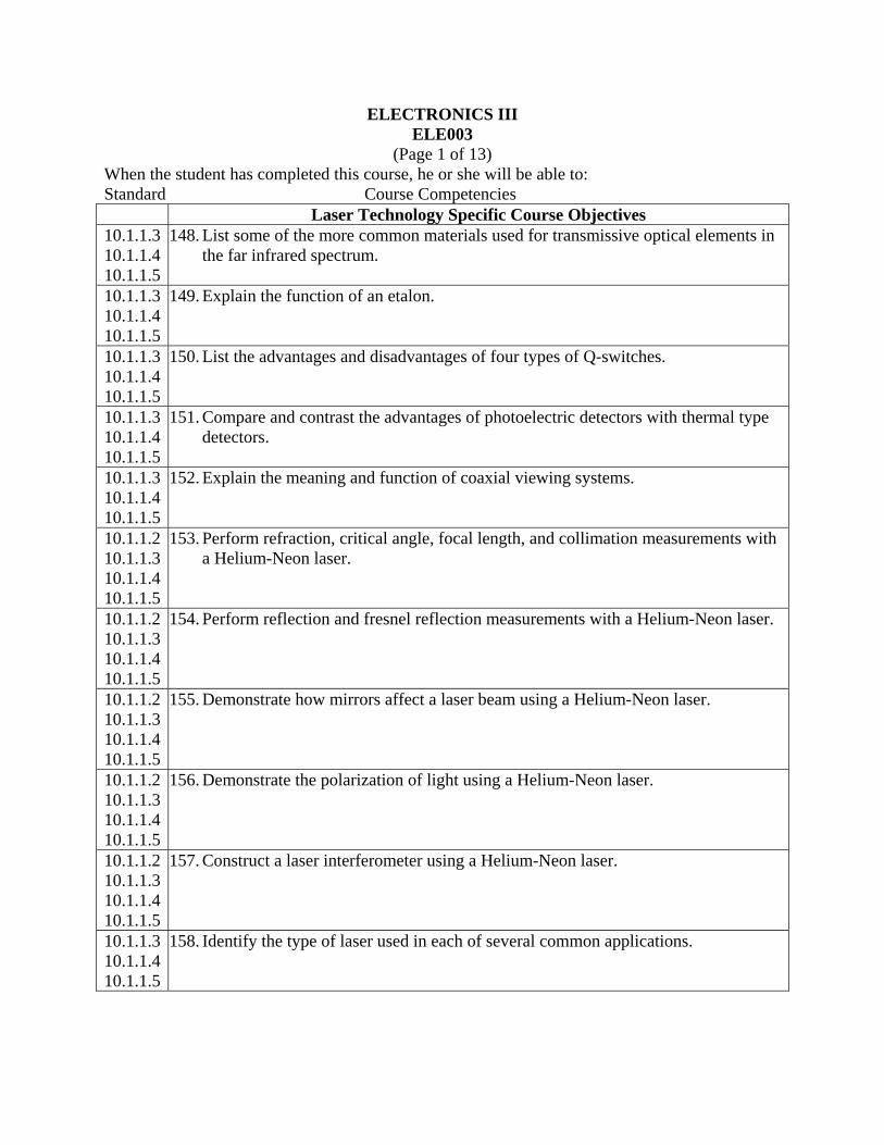
148. List some of the more common materials used for transmissive optical elements in the far infrared spectrum.
10.1.1.3 10.1.1.4 10.1.1.5
149. Explain the function of an etalon.
10.1.1.3 10.1.1.4 10.1.1.5
150. List the advantages and disadvantages of four types of Q-switches.
10.1.1.3 10.1.1.4 10.1.1.5
151. Compare and contrast the advantages of photoelectric detectors with thermal type detectors.
10.1.1.3 10.1.1.4 10.1.1.5
152. Explain the meaning and function of coaxial viewing systems.
10.1.1.2 10.1.1.3 10.1.1.4 10.1.1.5
153. Perform refraction, critical angle, focal length, and collimation measurements with a Helium-Neon laser.
10.1.1.2 10.1.1.3 10.1.1.4 10.1.1.5
154. Perform reflection and fresnel reflection measurements with a Helium-Neon laser.
10.1.1.2 10.1.1.3 10.1.1.4 10.1.1.5
155. Demonstrate how mirrors affect a laser beam using a Helium-Neon laser.
10.1.1.2 10.1.1.3 10.1.1.4 10.1.1.5
156. Demonstrate the polarization of light using a Helium-Neon laser.
10.1.1.2 10.1.1.3 10.1.1.4 10.1.1.5
157. Construct a laser interferometer using a Helium-Neon laser.
10.1.1.3 10.1.1.4 10.1.1.5
158. Identify the type of laser used in each of several common applications.

ELECTRONICS III ELE003
(Page 1 of 14) When the student has completed this course, he or she will be able to: Standard Course Competencies
Laser Technology Specific Course Objectives 10.1.1.3 10.1.1.4 10.1.1.5
159. Explain the difference between straight line projection systems rotating beam systems used in construction applications.
10.1.1.3 10.1.1.4 10.1.1.5
160. Describe the principle of operation of distance measurement/surveying systems and a laser interferometer.
10.1.1.3 10.1.1.4 10.1.1.5
161. List and briefly explain four interactions between light and materials that are important in material processing applications.
10.1.1.3 10.1.1.4 10.1.1.5
162. Associate a type of laser with each of several different material processing applications.
10.1.1.3 10.1.1.4 10.1.1.5
163. Explain the process known as keyhole welding.
10.1.1.3 10.1.1.4 10.1.1.5
164. Explain why a gas assist is used when cutting metals with a laser.
10.1.1.3 10.1.1.4 10.1.1.5
165. Compare and contrast material processing as it applies to metals and biological tissue.
10.1.1.3 10.1.1.4 10.1.1.5
166. List the three major types of lasers used in medical applications and, in general terms, describe their applications.
10.1.1.3 10.1.1.4 10.1.1.5
167. Describe the difference between surveying applications of distance measurement and military range-finding as to the type of lasers and their associated equipment.
10.1.1.3 10.1.1.4 10.1.1.5
168. Explain the term “thermal blooming” and explain how it limits the laser’s capability.
10.1.1.3 10.1.1.4 10.1.1.5
169. List and briefly explain the three most common uses of lasers in military applications.
10.1.1.3 10.1.1.4 10.1.1.5
170. Give a brief explanation of an optical communication system and its advantages over traditional communication systems.
10.1.1.3 10.1.1.4 10.1.1.5
171. List three applications of a scanning laser bar code reading system.

ELECTRONICS III ELE003
(Page 1 of 15) When the student has completed this course, he or she will be able to: Standard Course Competencies
Laser Technology Specific Course Objectives 10.1.1.3 10.1.1.4 10.1.1.5
172. Label the following portions of the human eye: Cornea, lens, aqueous, vitreous body, retina, choroids, sclera, fovea, macula, and optic nerve.
10.1.1.3 10.1.1.4 10.1.1.5
173. Identify the portion of the eye that is most susceptible to injury from each of the following types of lasers: Argon, HeNe, ruby, Nd:YAG, GaAs, and CO. Explain the difference between extended sources and point sources as they relate to the size of image formed on the retina of the eye.
10.1.1.3 10.1.1.4 10.1.1.5
174. Define the optical gain of the eye for light that is transmitted through the lens/cornea focusing system.
10.1.1.3 10.1.1.4 10.1.1.5
175. List and explain the three damage mechanisms that take place within the eye and the characteristics of the laser output that produce each.
10.1.1.3 10.1.1.4 10.1.1.5
176. Identify the layers of the skin and tell which lasers can penetrate or are absorbed by each of the layers.
10.1.1.3 10.1.1.4 10.1.1.5
177. Define optical density and relate the definition to laser eye ware safety specifications.
10.1.1.3 10.1.1.4 10.1.1.5
178. Identify two of the major laser safety standards published in the United States and explain who must comply with each standard.
10.1.1.3 10.1.1.4 10.1.1.5
179. List and explain three categories of control measures that are applied to laser systems.
10.1.1.3 10.1.1.4 10.1.1.5
180. Define and describe the responsibilities of the “laser safety officer” (LSO).
10.1.1.3 10.1.1.4 10.1.1.5
181. List six hazards, other than the laser beam itself, that are commonly associated with laser systems.
10.1.1.3 10.1.1.4 10.1.1.5
182. Explain the four safety classifications for lasers and how each is identified on a laser itself.
10.1.1.2 10.1.1.3 10.1.1.4 10.1.1.5
183. Demonstrate a safe use of the Helium Neon (HeNe) during lab time.
ELECTRONICS III ELE003
(Page 1 of 16) When the student has completed this course, he or she will be able to: Standard Course Competencies
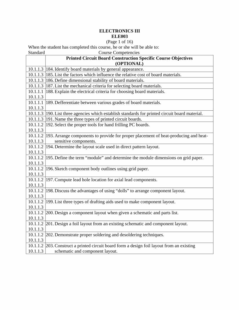
Printed Circuit Board Construction Specific Course Objectives (OPTIONAL)
10.1.1.3 184. Identify board materials by general appearance. 10.1.1.3 185. List the factors which influence the relative cost of board materials. 10.1.1.3 186. Define dimensional stability of board materials. 10.1.1.3 187. List the mechanical criteria for selecting board materials. 10.1.1.1 10.1.1.3
188. Explain the electrical criteria for choosing board materials.
10.1.1.1 10.1.1.3
189. Defferentiate between various grades of board materials.
10.1.1.3 190. List three agencies which establish standards for printed circuit board material. 10.1.1.3 191. Name the three types of printed circuit boards. 10.1.1.2 10.1.1.3
192. Select the proper tools for hand frilling PC boards.
10.1.1.2 10.1.1.3
193. Arrange components to provide for proper placement of heat-producing and heat-sensitive components.
10.1.1.2 10.1.1.3
194. Determine the layout scale used in direct pattern layout.
10.1.1.2 10.1.1.3
195. Define the term “module” and determine the module dimensions on grid paper.
10.1.1.2 10.1.1.3
196. Sketch component body outlines using grid paper.
10.1.1.2 10.1.1.3
197. Compute lead hole location for axial lead components.
10.1.1.2 10.1.1.3
198. Discuss the advantages of using “dolls” to arrange component layout.
10.1.1.2 10.1.1.3
199. List three types of drafting aids used to make component layout.
10.1.1.2 10.1.1.3
200. Design a component layout when given a schematic and parts list.
10.1.1.2 10.1.1.3
201. Design a foil layout from an existing schematic and component layout.
10.1.1.2 10.1.1.3
202. Demonstrate proper soldering and desoldering techniques.
10.1.1.2 10.1.1.3
203. Construct a printed circuit board form a design foil layout from an existing schematic and component layout.

ELECTRONICS III ELE003
(Page 1 of 17) When the student has completed this course, he or she will be able to: Standard Course Competencies
Robotics and Industrial Electronics Specific Course Objectives (OPTIONAL)
10.1.1.3 204. Discuss robot evolution and terminology generally associated with robots. 10.1.1.1 10.1.1.2 10.1.1.3 10.1.1.4 10.1.1.5
205. Demonstrate a knowledge of low-technology , medium-technology , and high-technology robot systems.
10.1.1.1 10.1.1.2 10.1.1.3 10.1.1.4 10.1.1.5
206. Demonstrate platform mobility using the ET-18 HERO Robotic Trainer’s gripper mechanism.
10.1.1.1 10.1.1.3 10.1.1.4 10.1.1.5
207. Discuss the typical forms of AC generation, AC motors, and basic hydraulic and pneumatic systems.
10.1.1.1 10.1.1.2 10.1.1.3 10.1.1.4 10.1.1.5
208. Use DC power to create positioning devices using nickel-cadmium batteries and gelled-electrolyte batteries.
10.1.1.1 10.1.1.3 10.1.1.4 10.1.1.5
209. Explain the workings of the DC motor, DC brushless motors, and stepper motors.
10.1.1.1 10.1.1.3 10.1.1.4 10.1.1.5
210. Define the terms and conventions discussed in microprocessing.
10.1.1.1 10.1.1.2 10.1.1.3 10.1.1.4 10.1.1.5
211. Demonstrate: Executing programs, addressing modes, binary arithmetic, two’s complement arithmetic and Boolean algebra using the ET-18 HERO Robotics Trainer.
10.1.1.1 10.1.1.3 10.1.1.4 10.1.1.5
212. Name and describe the following programming functions: Branching, conditional branching, algorithms, and interrupts.
ELECTRONICS III ELE003
(Page 1 of 18) When the student has completed this course, he or she will be able to: Standard Course Competencies
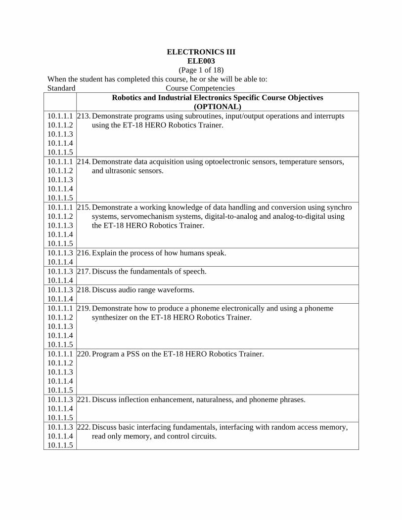
Robotics and Industrial Electronics Specific Course Objectives (OPTIONAL)
10.1.1.1 10.1.1.2 10.1.1.3 10.1.1.4 10.1.1.5
213. Demonstrate programs using subroutines, input/output operations and interrupts using the ET-18 HERO Robotics Trainer.
10.1.1.1 10.1.1.2 10.1.1.3 10.1.1.4 10.1.1.5
214. Demonstrate data acquisition using optoelectronic sensors, temperature sensors, and ultrasonic sensors.
10.1.1.1 10.1.1.2 10.1.1.3 10.1.1.4 10.1.1.5
215. Demonstrate a working knowledge of data handling and conversion using synchro systems, servomechanism systems, digital-to-analog and analog-to-digital using the ET-18 HERO Robotics Trainer.
10.1.1.3 10.1.1.4
216. Explain the process of how humans speak.
10.1.1.3 10.1.1.4
217. Discuss the fundamentals of speech.
10.1.1.3 10.1.1.4
218. Discuss audio range waveforms.
10.1.1.1 10.1.1.2 10.1.1.3 10.1.1.4 10.1.1.5
219. Demonstrate how to produce a phoneme electronically and using a phoneme synthesizer on the ET-18 HERO Robotics Trainer.
10.1.1.1 10.1.1.2 10.1.1.3 10.1.1.4 10.1.1.5
220. Program a PSS on the ET-18 HERO Robotics Trainer.
10.1.1.3 10.1.1.4 10.1.1.5
221. Discuss inflection enhancement, naturalness, and phoneme phrases.
10.1.1.3 10.1.1.4 10.1.1.5
222. Discuss basic interfacing fundamentals, interfacing with random access memory, read only memory, and control circuits.

ELECTRONICS III ELE003
(Page 1 of 19) When the student has completed this course, he or she will be able to: Standard Course Competencies
Robotics and Industrial Electronics Specific Course Objectives (OPTIONAL)
10.1.1.3 223. Explain the classifications of industrial robots and considerations for their application.
10.1.1.1 10.1.1.2 10.1.1.3 10.1.1.4 10.1.1.5
224. Demonstrate straight line programs using the ET-18 HERO Robotics Trainer.
10.1.1.1 10.1.1.2 10.1.1.3 10.1.1.4 10.1.1.5
225. Demonstrate the use of “open loop” control of a DC stepper motor using the ET-18 HERO robotics trainer.
10.1.1.1 10.1.1.2 10.1.1.3 10.1.1.4 10.1.1.5
226. Demonstrate a robot voice routine using the ET-18 HERO Robotics Trainer.
10.1.1.1 10.1.1.2 10.1.1.3 10.1.1.4 10.1.1.5
227. Demonstrate robot language using sensors and sound on the ET-18 HERO Robotics Trainer.
10.1.1.1 10.1.1.2 10.1.1.3 10.1.1.4 10.1.1.5
228. Demonstrate how to modify a taught program on the ET-18 HERO Robotics Trainer.
10.1.1.1 10.1.1.2 10.1.1.3 10.1.1.4 10.1.1.5
229. Troubleshoot board-level problems on the ET-18 HERO Robotics trainer using a Huntron Tracker and a digital multimeter.