Embed Size (px)
Citation preview
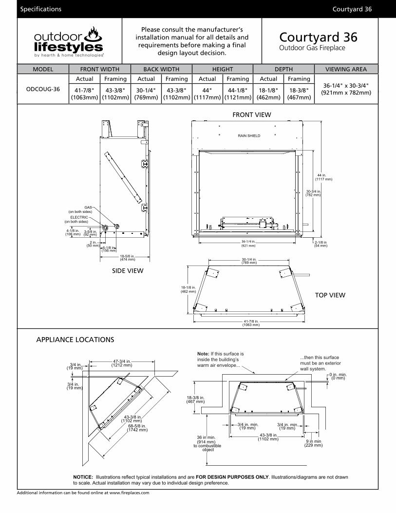
Specifications
Additional information can be found online at www.fireplaces.com
MODEL HEIGHT FRONT WIDTH BACK WIDTH DEPTH VIEWING AREA
Actual Framing Actual Framing Actual Framing Actual Framing
Note: If this surface is inside the building’s warm air envelope...
...then this surface must be an exterior wall system.
3/4 in.(19 mm)
47-3/4 in.(1212 mm)
3/4 in.(19 mm)
43-3/8 in.(1102 mm)
68-5/8 in.(1742 mm)
18-3/8 in.(467 mm)
3/4 in. min.(19 mm)
3/4 in. min.(19 mm)
0 in. min.(0 mm)
43-3/8 in.(1102 mm) 9 in min
(229 mm)
36 in min.(914 mm)
to combustible object
ODCOUG-36
NOTICE: Illustrations reflect typical installations and are FOR DESIGN PURPOSES ONLY. Illustrations/diagrams are not drawn to scale. Actual installation may vary due to individual design preference.
Please consult the manufacturer’s installation manual for all details and requirements before making a final
design layout decision.
Courtyard 36Outdoor Gas Fireplace
MODEL FRONT WIDTH BACK WIDTH HEIGHT DEPTH VIEWING AREA
ODCOUG-36
Actual Framing Actual Framing Actual Framing Actual Framing36-1/4" x 30-3/4"
(921mm x 782mm)41-7/8" (1063mm)
43-3/8" (1102mm)
30-1/4"(769mm)
43-3/8" (1102mm)
44"(1117mm)
44-1/8"(1121mm)
18-1/8"(462mm)
18-3/8"(467mm)
Courtyard 36
FRONT VIEW
TOP VIEW
SIDE VIEW
APPLIANCE LOCATIONS
ODCOUG-36
30-1/4 in. (769 mm)
41-7/8 in.(1063 mm)
18-1/8 in.(462 mm)
44 in.(1117 mm)
2-1/8 in(54 mm)
30-3/4 in. (782 mm)
2 in.(50 mm)
3-5/8 in.(92 mm)
4-1/8 in.(106 mm)
6-1/8 in.(156 mm)
18-5/8 in.(474 mm)
RAIN SHIELD
ELECTRIC(on both sides)
GAS (on both sides)
36-1/4 in.(921 mm)
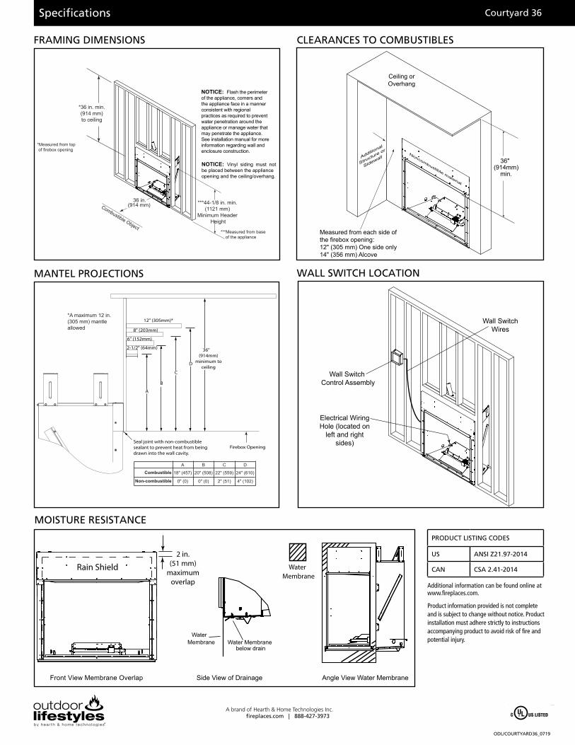
Specifications
ODL/COURTYARD36_0719
A brand of Hearth & Home Technologies Inc.fireplaces.com | 888-427-3973
FRAMING DIMENSIONS CLEARANCES TO COMBUSTIBLES
MANTEL PROJECTIONS
Courtyard 36
*A maximum 12 in. (305 mm) mantle allowed
CombustibleA
18" (457)
0" (0)
B
20" (508)
0" (0)
C
22" (559)
2" (51)
D
24" (610)
4" (102)Non-combustible
2-1/2" (64mm)
6" (152mm)
8" (203mm)
Firebox Opening
A
36" (914mm)
minimum to ceiling
12" (305mm)*
Seal joint with non-combustible sealant to prevent heat from being drawn into the wall cavity.
B
C
D
NOTICE: Vinyl siding must not be placed between the appliance opening and the ceiling/overhang.
NOTICE: Flash the perimeter of the appliance, corners and the appliance face in a manner consistent with regional practices as required to prevent water penetration around the appliance or manage water that may penetrate the appliance. See installation manual for more information regarding wall and enclosure construction.
*36 in. min.(914 mm)to ceiling
Combustible Object
36 in.(914 mm)
*Measured from top of firebox opening
***Measured from base of the appliance
***44-1/8 in. min.(1121 mm)
Minimum Header Height
Additional
Structure or
Sidewall
Ceiling orOverhang
36"(914mm)
min.
Measured from each side of the firebox opening: 12" (305 mm) One side only14" (356 mm) Alcove
Noncombustible material
Additional information can be found online at www.fireplaces.com.
Product information provided is not complete and is subject to change without notice. Product installation must adhere strictly to instructions accompanying product to avoid risk of fire and potential injury.
PRODUCT LISTING CODES
US ANSI Z21.97-2014
CAN CSA 2.41-2014
WALL SWITCH LOCATION
Wall Switch Control Assembly
Wall SwitchWires
Electrical Wiring Hole (located on
left and right sides)
Front View Membrane Overlap Side View of Drainage Angle View Water Membrane
Water Membrane Water Membrane
below drain
Water Membrane
2 in.(51 mm)
maximum overlap
Rain Shield
MOISTURE RESISTANCE


![914 mavroidis[2]](https://img.pdfslide.net/doc/110x75/55a125b71a28ab49388b45db/914-mavroidis2.jpg)