Embed Size (px)
Citation preview

ACT 250TURBOMOLECULAR PUMP CONTROLLER
FOR ATP 150 AND ATP 400
ATP Series User’s Manual addendum

ContentsACT 250 addendum
Alcatel Vacuum Technology France - ACT 250 addendum 1
Janu
ary
2001
Commissioning
Presentation ■ The ACT 250 controller . . . . . . . . . . . . . . ■ p. 3
■ Main characteristics . . . . . . . . . . . . . . . . ■ p. 3
■ Accessories. . . . . . . . . . . . . . . . . . . . . . ■ p. 4■■ Pump supply cable■■ “End-user” kit
■ Control modes for ACT 250 “box” controller . . . . . . . . . . . . . . . . . . . . . . . ■ p. 5■■ Local control mode■■ Remote control
■ Control modes for ACT 250 “OEM” controller . . . . . . . . . . . . . . . . . . . . . . . ■ p. 6■■ Local control mode■■ Remote control
■ ACT 250 controller technical characteristics . . ■ p. 7■■ Dimensions
■ Safety instructions . . . . . . . . . . . . . . . . . ■ p. 9
■ ACT 250 electrical connections . . . . . . . . . . ■ p. 10
■ Characteristics of the ACT 250“Remote” connector . . . . . . . . . . . . . . . . ■ p. 11■■ Voltage control mode■■ Principle of voltage-controlled
opto-isolated inputs■■ Signalling on output contacts
■ Wiring the ACT 250 “Remote” connector . . . ■ p. 13■■ Use in local mode■■ Use in remote control mode
ContentsACT 250 addendum
Alcatel Vacuum Technology France - ACT 250 addendum2
Janu
ary
2001
Use
Commissioning(continued)
■ Controlling the pump from theACT 250 controller . . . . . . . . . . . . . . . . . ■ p. 24
■ Controller functions . . . . . . . . . . . . . . . . . ■ p. 26■■ Precautions■■ Operation in local mode■■ Fault management
■ RS 232/485 serial link . . . . . . . . . . . . . . ■ p. 14■■ Wiring the RS 232 or RS 485
serial link■■ Configuring the RS 232 or RS 485
serial link■■ Use
■ Detailed description of RS commands. . . . . . ■ p. 15■■ Syntax conventions applicable to
all commands
Presentation
Alcatel Vacuum Technology France - ACT 250 addendum 3
Janu
ary
2001
The ACT 250 controller
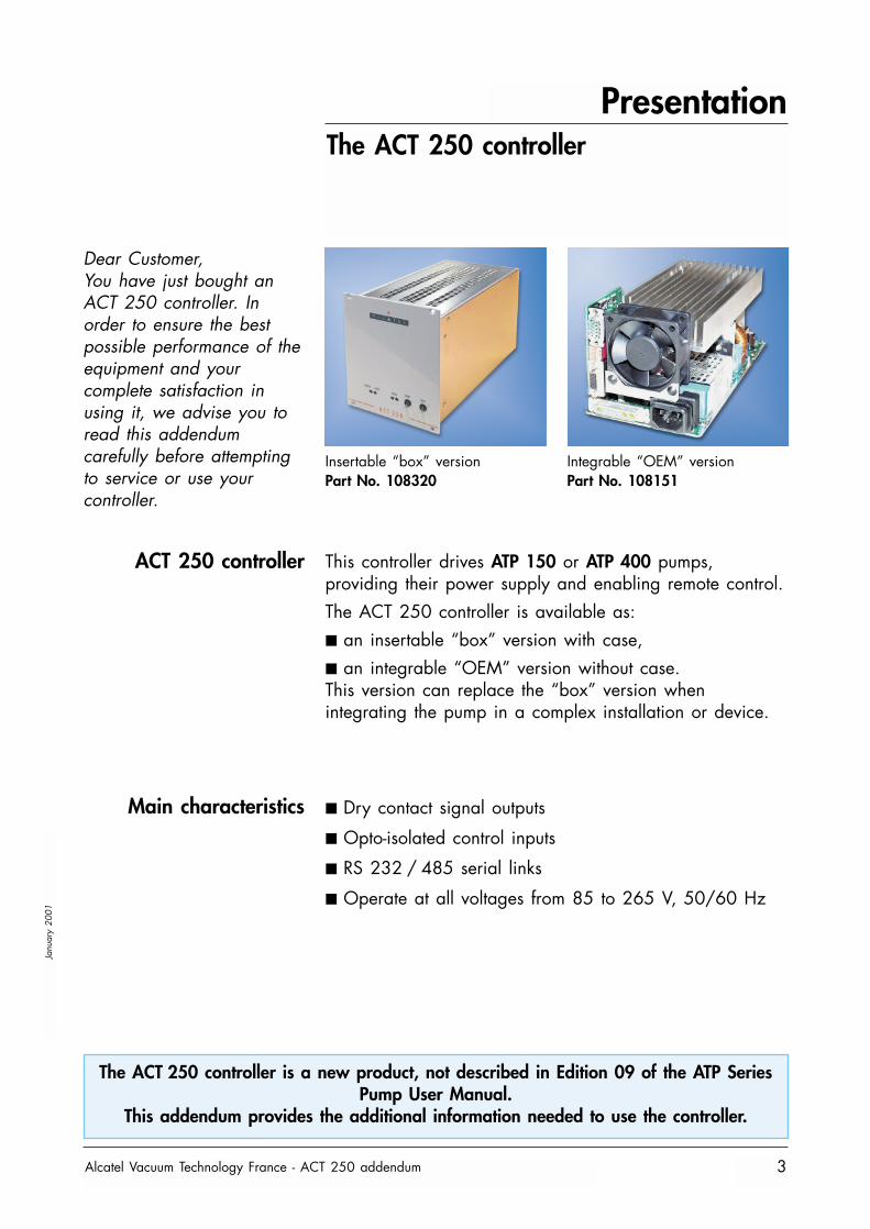
Dear Customer,You have just bought anACT 250 controller. Inorder to ensure the bestpossible performance of theequipment and yourcomplete satisfaction inusing it, we advise you toread this addendumcarefully before attemptingto service or use yourcontroller.
Insertable “box” versionPart No. 108320
Integrable “OEM” versionPart No. 108151
ACT 250 controller
Main characteristics
This controller drives ATP 150 or ATP 400 pumps,providing their power supply and enabling remote control.The ACT 250 controller is available as:■ an insertable “box” version with case,■ an integrable “OEM” version without case.This version can replace the “box” version whenintegrating the pump in a complex installation or device.
■ Dry contact signal outputs
■ Opto-isolated control inputs
■ RS 232 / 485 serial links
■ Operate at all voltages from 85 to 265 V, 50/60 Hz
The ACT 250 controller is a new product, not described in Edition 09 of the ATP SeriesPump User Manual.
This addendum provides the additional information needed to use the controller.
Presentation
Alcatel Vacuum Technology France - ACT 250 addendum4
Janu
ary
2001
Accessories
Pump power supplycable
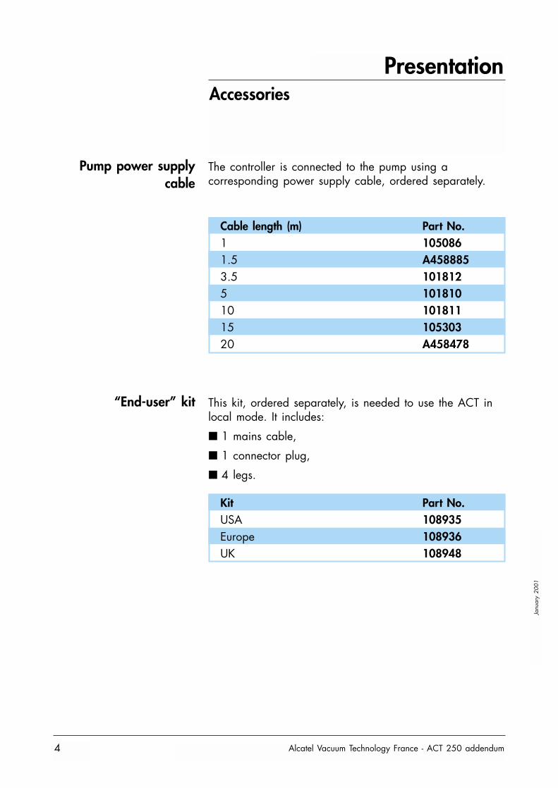
The controller is connected to the pump using acorresponding power supply cable, ordered separately.
Cable length (m) Part No.1 1050861.5 A4588853.5 1018125 10181010 10181115 10530320 A458478
Kit Part No.USA 108935Europe 108936UK 108948
“End-user” kit This kit, ordered separately, is needed to use the ACT inlocal mode. It includes:
■ 1 mains cable,
■ 1 connector plug,
■ 4 legs.
Presentation
Alcatel Vacuum Technology France - ACT 250 addendum 5
Janu
ary
2001
ACT 250 “box” controller control modes
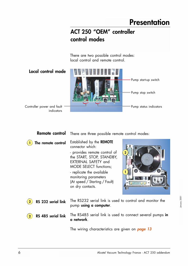
Local control mode
A C T 2 5 0A C T 2 5 0
POWER FAULT SPEED START STOP
1
2
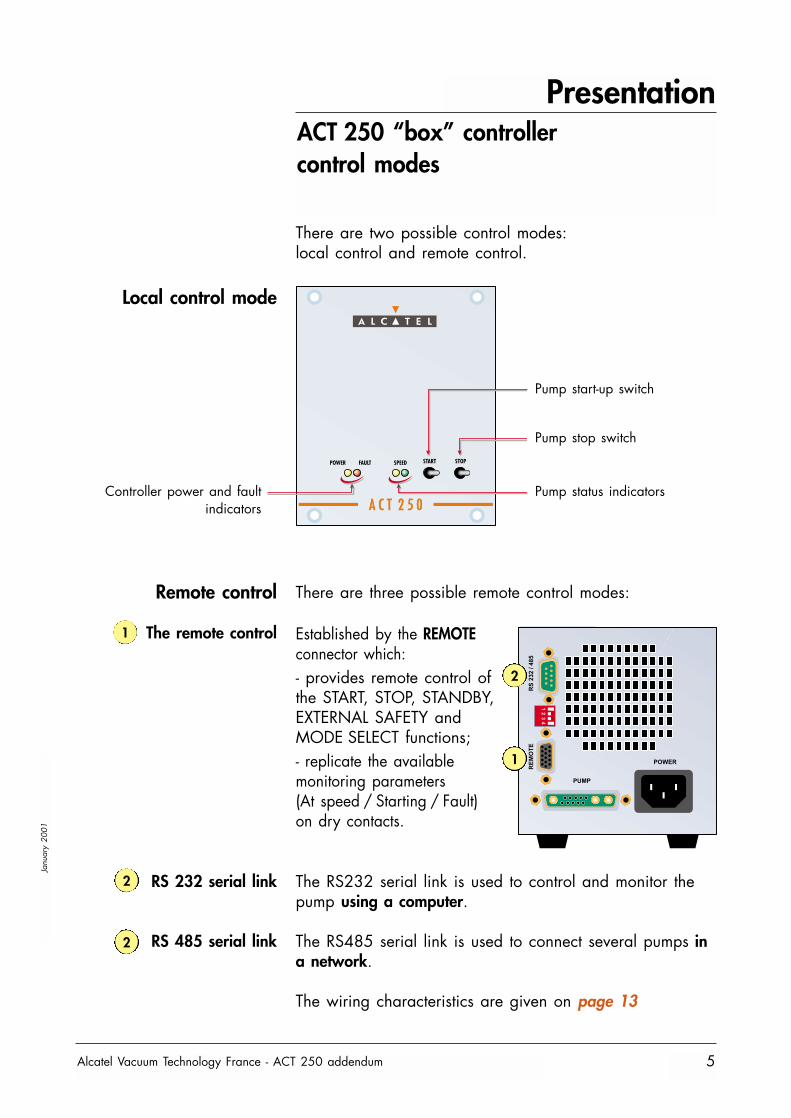
Pump start-up switch
Pump stop switch
Pump status indicatorsController power and faultindicators
Remote control
The remote control Established by the REMOTEconnector which:- provides remote control ofthe START, STOP, STANDBY,EXTERNAL SAFETY andMODE SELECT functions;- replicate the availablemonitoring parameters(At speed / Starting / Fault)on dry contacts.
The RS232 serial link is used to control and monitor thepump using a computer.
The RS485 serial link is used to connect several pumps ina network.
The wiring characteristics are given on page 13
RS 232 serial link
RS 485 serial link
1
2
2
There are three possible remote control modes:
There are two possible control modes: local control and remote control.
Presentation
Alcatel Vacuum Technology France - ACT 250 addendum6
Janu
ary
2001
ACT 250 “OEM” controller control modes
Pump start-up switch
Pump stop switch
Pump status indicatorsController power and faultindicators
Local control mode
2
1
Remote control
The remote control Established by the REMOTEconnector which:- provides remote control ofthe START, STOP, STANDBY,EXTERNAL SAFETY andMODE SELECT functions;- replicate the availablemonitoring parameters(At speed / Starting / Fault)on dry contacts.
The RS232 serial link is used to control and monitor thepump using a computer.
The RS485 serial link is used to connect several pumps ina network.
The wiring characteristics are given on page 13
RS 232 serial link
RS 485 serial link
1
2
2
There are two possible control modes: local control and remote control.
There are three possible remote control modes:
Presentation
Alcatel Vacuum Technology France - ACT 250 addendum 7
Janu
ary
2001
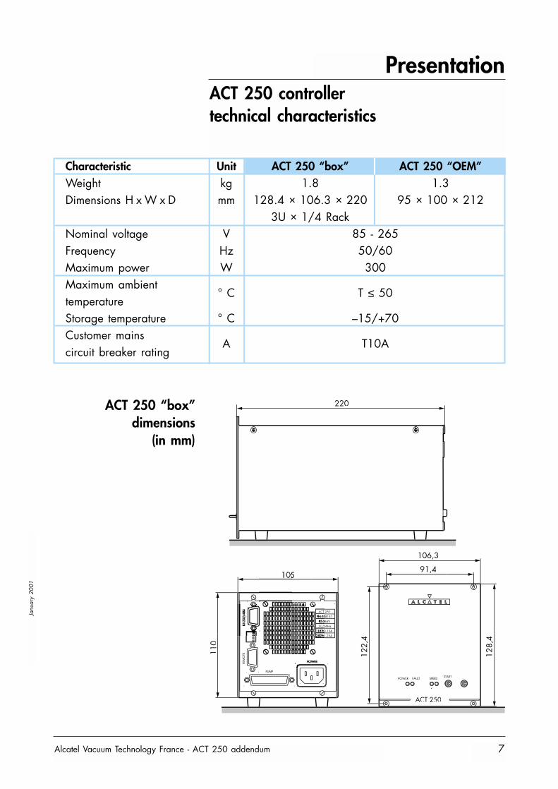
ACT 250 controller technical characteristics
Characteristic Unit ACT 250 “box” ACT 250 “OEM”Weight kg 1.8 1.3Dimensions H x W x D mm 128.4 × 106.3 × 220 95 × 100 × 212
3U × 1/4 RackNominal voltage V 85 - 265Frequency Hz 50/60Maximum power W 300Maximum ambient
° C T ≤ 50temperatureStorage temperature ° C –15/+70Customer mains
A T10Acircuit breaker rating
ACT 250 “box”dimensions
(in mm)
110
105
PUMP
60Hz
250
ACT 250
POWER FAULT SPEED
122,
4
< =
106,3
91,4
128,
4
220
Presentation
Alcatel Vacuum Technology France - ACT 250 addendum8
Janu
ary
2001
ACT 250 controller technical characteristics
RS232/485
PUMP
REMOTE
POWER SUPPLY
212
4 tr Ø 3,2
POW
ER S
UPP
LYFA
ULT
< SP
EED
AT
SPEE
DST
ART
STO
P
153,1
8 m
ini.
L1
L2
T4,75
90,1
5
18,67
95 m
axi.
100
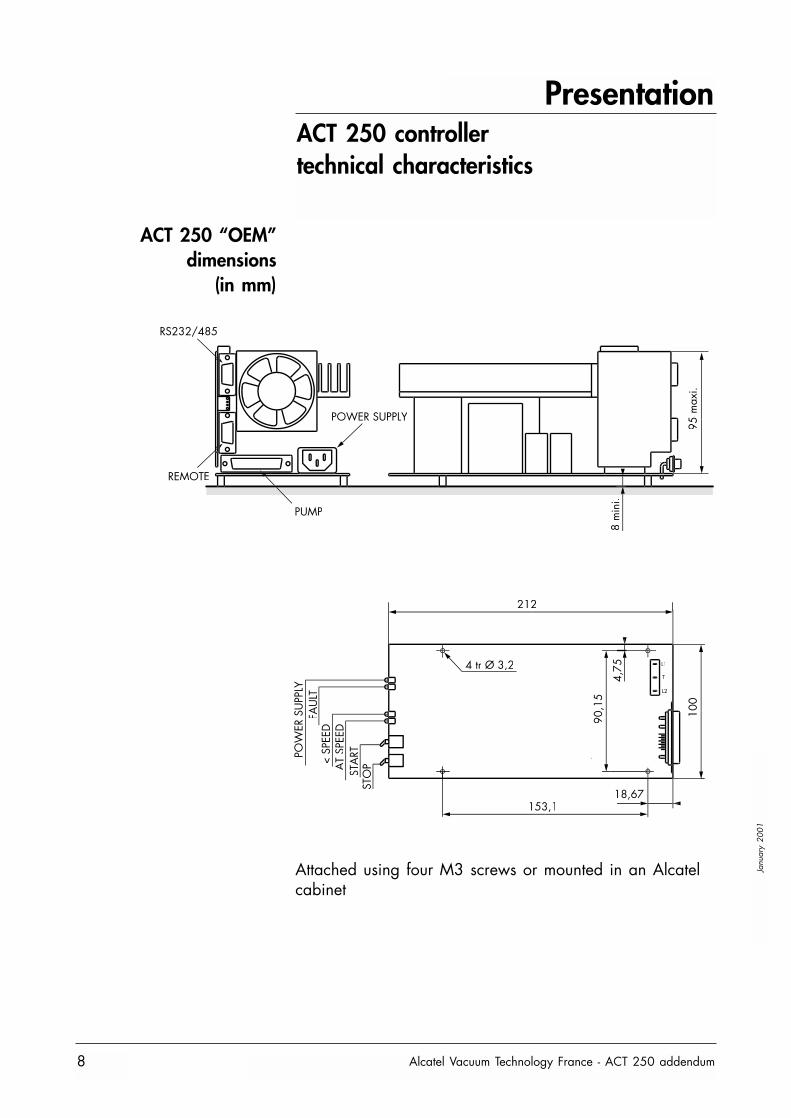
ACT 250 “OEM”dimensions
(in mm)
Attached using four M3 screws or mounted in an Alcatelcabinet

Commissioning
Alcatel Vacuum Technology France - ACT 250 addendum 9
Janu
ary
2001
Safety instructions
Before switching on the controller, the user shouldstudy the manual and follow the safetyinstructions listed in the compliance certificate
booklet supplied with the pump.See sheet B10 in the ATP pump User Manual.
Commissioning
Alcatel Vacuum Technology France - ACT 250 addendum10
Janu
ary
2001
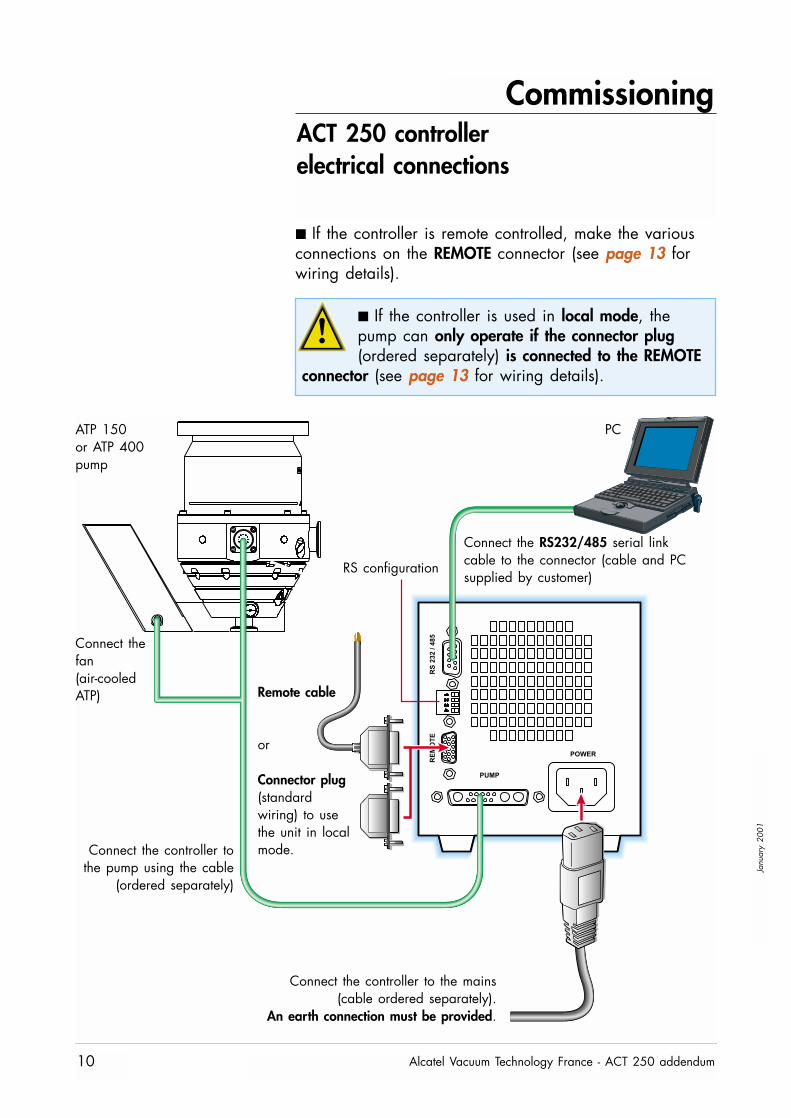
ACT 250 controllerelectrical connections
Connect the RS232/485 serial linkcable to the connector (cable and PCsupplied by customer)
■ If the controller is remote controlled, make the variousconnections on the REMOTE connector (see page 13 forwiring details).
■ If the controller is used in local mode, thepump can only operate if the connector plug(ordered separately) is connected to the REMOTE
connector (see page 13 for wiring details).
Connect the controller tothe pump using the cable
(ordered separately)
Connect thefan (air-cooledATP) Remote cable
or
Connector plug(standardwiring) to usethe unit in localmode.
ATP 150or ATP 400pump
PC
Connect the controller to the mains (cable ordered separately).
An earth connection must be provided.
RS configuration
Commissioning
Alcatel Vacuum Technology France - ACT 250 addendum 11
Janu
ary
2001
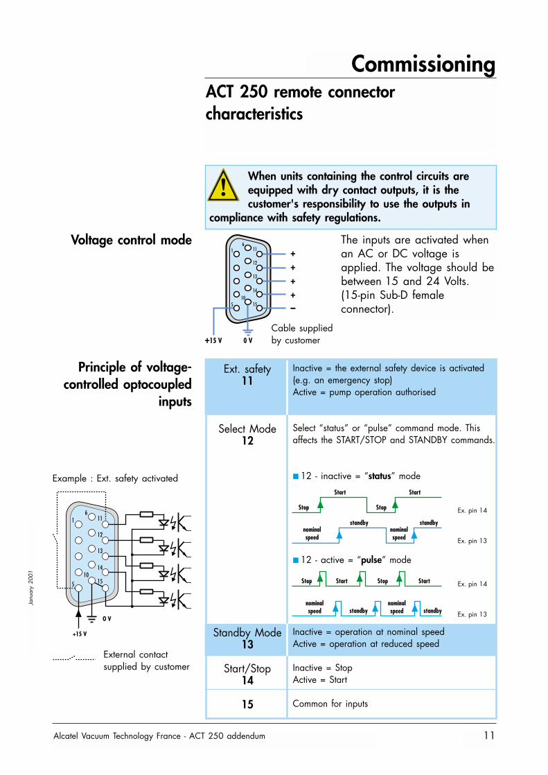
ACT 250 remote connector characteristics
When units containing the control circuits areequipped with dry contact outputs, it is thecustomer's responsibility to use the outputs in
compliance with safety regulations.
Voltage control mode
Principle of voltage-controlled optocoupled
inputs
16
11
12
13
1410
155
++++–
+15 V 0 V
Cable suppliedby customer
The inputs are activated whenan AC or DC voltage isapplied. The voltage should bebetween 15 and 24 Volts.(15-pin Sub-D femaleconnector).
Ext. safety11
Select Mode12
Standby Mode13
Start/Stop14
15
Inactive = the external safety device is activated(e.g. an emergency stop)Active = pump operation authorised
Select “status” or “pulse” command mode. Thisaffects the START/STOP and STANDBY commands.
■ 12 - inactive = “status” mode
■ 12 - active = “pulse” mode
Inactive = operation at nominal speedActive = operation at reduced speed
Inactive = StopActive = Start
Common for inputs
1
O V
+15 V
611
12
13
1410
155
Example : Ext. safety activated
External contactsupplied by customer
Start
Stop
Start
Ex. pin 14
Ex. pin 13
Stop
standby standbynominalspeed
nominalspeed
Ex. pin 14
Ex. pin 13
StartStop StartStop
standby standbynominalspeed
nominalspeed
Commissioning
Alcatel Vacuum Technology France - ACT 250 addendum12
Janu
ary
2001
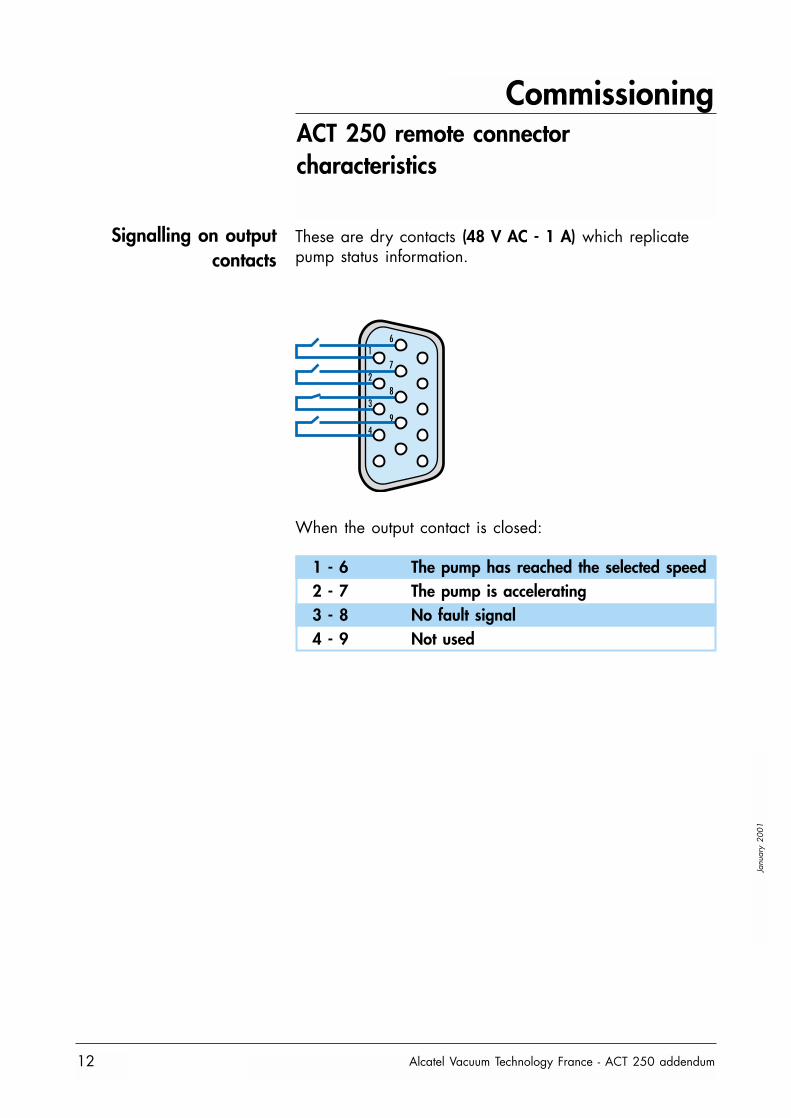
ACT 250 remote connector characteristics
Signalling on outputcontacts
These are dry contacts (48 V AC - 1 A) which replicatepump status information.
When the output contact is closed:
16
27
38
49
1 - 6 The pump has reached the selected speed2 - 7 The pump is accelerating3 - 8 No fault signal4 - 9 Not used
Commissioning
Alcatel Vacuum Technology France - ACT 250 addendum 13
Janu
ary
2001
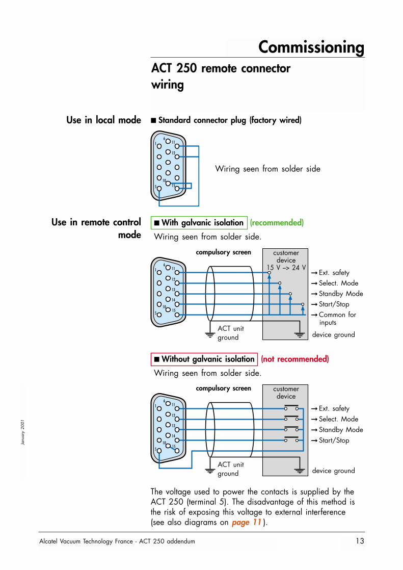
ACT 250 remote connector wiring
Use in local mode ■ Standard connector plug (factory wired)
Use in remote controlmode
■ Without galvanic isolation (not recommended)
Wiring seen from solder side.
■ With galvanic isolation (recommended)
Wiring seen from solder side.
16
11
12
10155
16
11
12
13
14
1015
5
16
11
12
13
14
1015
5
compulsory screen customerdevice
ACT unitground device ground
compulsory screen customerdevice
15 V –> 24 V
ACT unitground device ground
Wiring seen from solder side
➞ Ext. safety➞ Select. Mode➞ Standby Mode➞ Start/Stop➞ Common for
inputs
➞ Ext. safety➞ Select. Mode➞ Standby Mode➞ Start/Stop
The voltage used to power the contacts is supplied by theACT 250 (terminal 5). The disadvantage of this method isthe risk of exposing this voltage to external interference (see also diagrams on page 11 ).
Commissioning
Alcatel Vacuum Technology France - ACT 250 addendum14
Janu
ary
2001
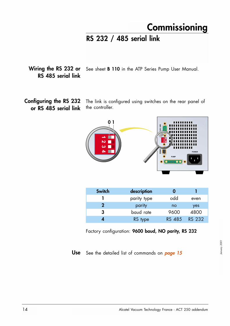
RS 232 / 485 serial link
Wiring the RS 232 orRS 485 serial link
See sheet B 110 in the ATP Series Pump User Manual.
Configuring the RS 232or RS 485 serial link
The link is configured using switches on the rear panel ofthe controller.
0 1
Switch description 0 11 parity type odd even2 parity no yes3 baud rate 9600 48004 RS type RS 485 RS 232
Factory configuration: 9600 baud, NO parity, RS 232
Use See the detailed list of commands on page 15
Commissioning
Alcatel Vacuum Technology France - ACT 250 addendum 15
Janu
ary
2001
Detailed description of RS commands
Syntax conventionsapplicable to all
commands
Status values
Error messages
ADR
Syntax
Result
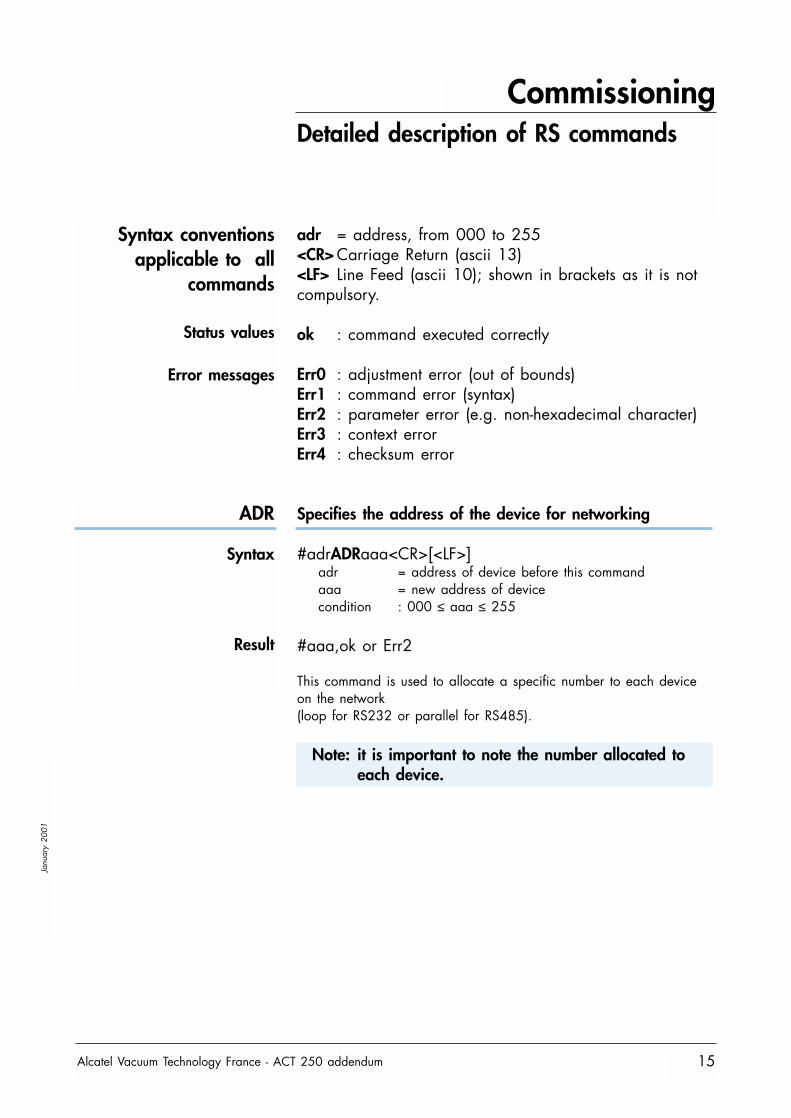
adr = address, from 000 to 255<CR> Carriage Return (ascii 13)<LF> Line Feed (ascii 10); shown in brackets as it is notcompulsory.
ok : command executed correctly
Err0 : adjustment error (out of bounds)Err1 : command error (syntax)Err2 : parameter error (e.g. non-hexadecimal character)Err3 : context errorErr4 : checksum error
Specifies the address of the device for networking
#adrADRaaa<CR>[<LF>]adr = address of device before this commandaaa = new address of devicecondition : 000 ≤ aaa ≤ 255
#aaa,ok or Err2
This command is used to allocate a specific number to each deviceon the network(loop for RS232 or parallel for RS485).
Note: it is important to note the number allocated toeach device.
Commissioning
Alcatel Vacuum Technology France - ACT 250 addendum16
Janu
ary
2001
Detailed description of RS commands
CKS
Syntax
Result
CYC
Syntax
Result
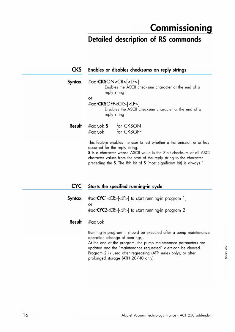
Enables or disables checksums on reply strings
#adrCKSON<CR>[<LF>]Enables the ASCII checksum character at the end of a reply string
or#adrCKSOFF<CR>[<LF>]
Disables the ASCII checksum character at the end of a reply string
#adr,ok,S for CKSON#adr,ok for CKSOFF
This feature enables the user to test whether a transmission error hasoccurred for the reply string.S is a character whose ASCII value is the 7-bit checksum of all ASCIIcharacter values from the start of the reply string to the characterpreceding the S. The 8th bit of S (most significant bit) is always 1.
Starts the specified running-in cycle
#adrCYC1<CR>[<LF>] to start running-in program 1,or#adrCYC2<CR>[<LF>] to start running-in program 2
#adr,ok
Running-in program 1 should be executed after a pump maintenanceoperation (change of bearings).At the end of the program, the pump maintenance parameters areupdated and the “maintenance requested” alert can be cleared.Program 2 is used after regreasing (ATP series only), or afterprolonged storage (ATH 20/40 only).
Commissioning
Alcatel Vacuum Technology France - ACT 250 addendum 17
Janu
ary
2001
Detailed description of RS commands
DLI
Syntax
Result
See also: DLR
DLR
Syntax
Result
See also: DLI, LNG, SEP, SHT
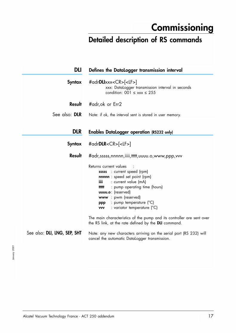
Enables DataLogger operation (RS232 only)
#adrDLR<CR>[<LF>]
#adr,sssss,nnnnn,iiii,ttttt,uuuu.o,www,ppp,vvv
Returns current values :sssss : current speed (rpm)nnnnn : speed set point (rpm)iiii : current value (mA)ttttt : pump operating time (hours)uuuu.o : (reserved)www : pwm (reserved)ppp : pump temperature (°C)vvv : variator temperature (°C)
The main characteristics of the pump and its controller are sent overthe RS link, at the rate defined by the DLI command.
Note: any new characters arriving on the serial port (RS 232) willcancel the automatic DataLogger transmission.
Defines the DataLogger transmission interval
#adrDLIxxx<CR>[<LF>]xxx: DataLogger transmission interval in secondscondition: 001 ≤ xxx ≤ 255
#adr,ok or Err2
Note: if ok, the interval sent is stored in user memory.
Commissioning
Alcatel Vacuum Technology France - ACT 250 addendum18
Janu
ary
2001
Detailed description of RS commands
HDR
Syntax
Result
IDN
Syntax
Result
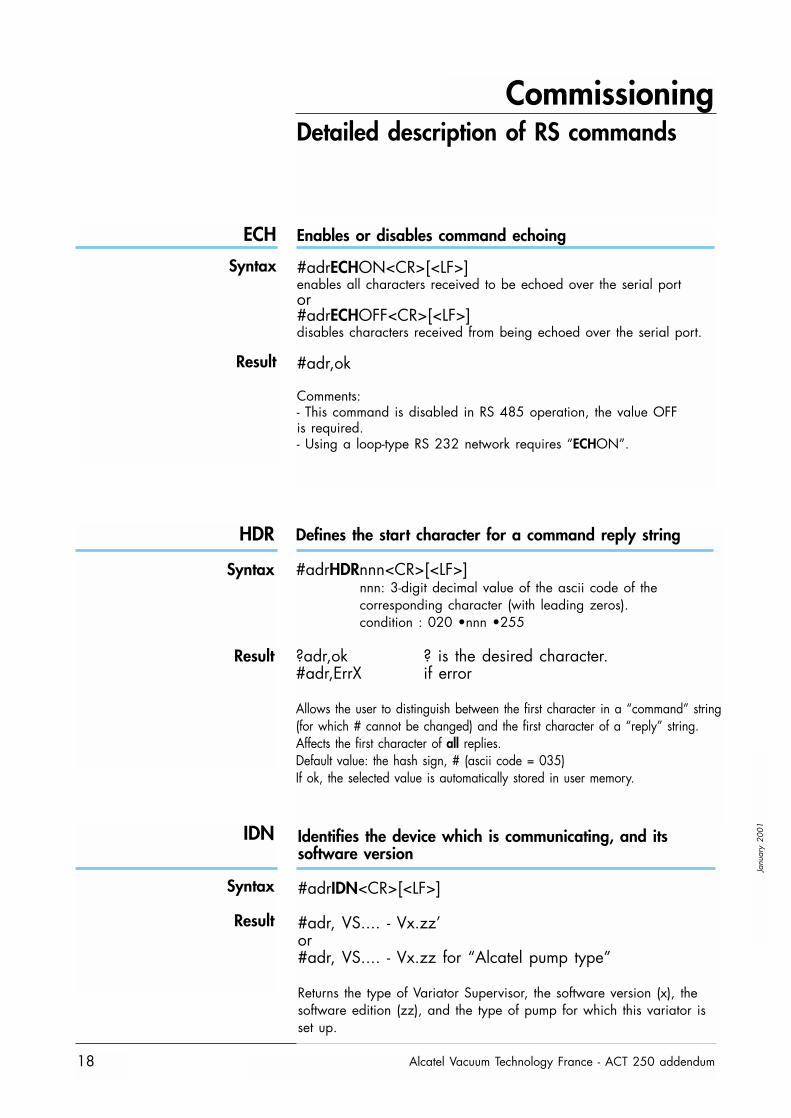
Identifies the device which is communicating, and itssoftware version
#adrIDN<CR>[<LF>]
#adr, VS.... - Vx.zz’or#adr, VS.... - Vx.zz for “Alcatel pump type”
Returns the type of Variator Supervisor, the software version (x), thesoftware edition (zz), and the type of pump for which this variator isset up.
Defines the start character for a command reply string
#adrHDRnnn<CR>[<LF>]nnn: 3-digit decimal value of the ascii code of thecorresponding character (with leading zeros).condition : 020 •nnn •255
?adr,ok ? is the desired character.#adr,ErrX if error
Allows the user to distinguish between the first character in a “command” string(for which # cannot be changed) and the first character of a “reply” string.Affects the first character of all replies.Default value: the hash sign, # (ascii code = 035)If ok, the selected value is automatically stored in user memory.
ECH
Syntax
Result
Enables or disables command echoing
#adrECHON<CR>[<LF>]enables all characters received to be echoed over the serial portor#adrECHOFF<CR>[<LF>]disables characters received from being echoed over the serial port.
#adr,ok
Comments:- This command is disabled in RS 485 operation, the value OFFis required.- Using a loop-type RS 232 network requires “ECHON”.
Commissioning
Alcatel Vacuum Technology France - ACT 250 addendum 19
Janu
ary
2001
Detailed description of RS commands
LEV
Syntax
Result
LNG
Syntax
Result
See also: SHT
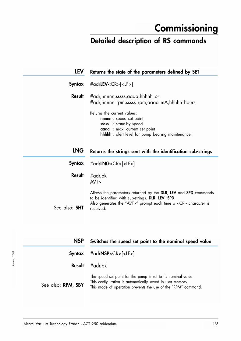
Returns the state of the parameters defined by SET
#adrLEV<CR>[<LF>]
#adr,nnnnn,sssss,aaaa,hhhhh or#adr,nnnnn rpm,sssss rpm,aaaa mA,hhhhh hours
Returns the current values:nnnnn : speed set pointsssss : stand-by speedaaaa : max. current set pointhhhhh : alert level for pump bearing maintenance
Returns the strings sent with the identification sub-strings
#adrLNG<CR>[<LF>]
#adr,okAVT>
Allows the parameters returned by the DLR, LEV and SPD commandsto be identified with sub-strings. DLR, LEV, SPD.Also generates the “AVT>” prompt each time a <CR> character isreceived.
NSP
Syntax
Result
See also: RPM, SBY
Switches the speed set point to the nominal speed value
#adrNSP<CR>[<LF>]
#adr,ok
The speed set point for the pump is set to its nominal value.This configuration is automatically saved in user memory.This mode of operation prevents the use of the “RPM” command.
Commissioning
Alcatel Vacuum Technology France - ACT 250 addendum20
Janu
ary
2001
Detailed description of RS commands
OPT
Syntax
Result
See also: SEL
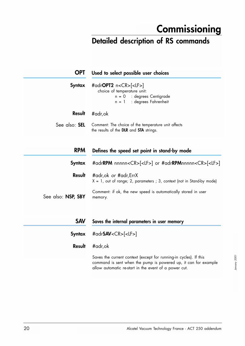
Used to select possible user choices
#adrOPT2 n<CR>[<LF>]choice of temperature unit:
n = 0 : degrees Centigraden = 1 : degrees Fahrenheit
#adr,ok
Comment: The choice of the temperature unit affectsthe results of the DLR and STA strings.
RPM
Syntax
Result
See also: NSP, SBY
Defines the speed set point in stand-by mode
#adrRPM nnnnn<CR>[<LF>] or #adrRPMnnnnn<CR>[<LF>]
#adr,ok or #adr,ErrXX = 1, out of range; 2, parameters ; 3, context (not in Stand-by mode)
Comment: if ok, the new speed is automatically stored in usermemory.
Saves the internal parameters in user memory
#adrSAV<CR>[<LF>]
#adr,ok
Saves the current context (except for running-in cycles). If thiscommand is sent when the pump is powered up, it can for exampleallow automatic re-start in the event of a power cut.
SAV
Syntax
Result
Commissioning
Alcatel Vacuum Technology France - ACT 250 addendum 21
Janu
ary
2001
Detailed description of RS commands
SBY
Syntax
Result
See also: NSP, RPM
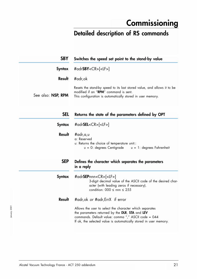
Switches the speed set point to the stand-by value
#adrSBY<CR>[<LF>]
#adr,ok
Resets the stand-by speed to its last stored value, and allows it to bemodified if an “RPM” command is sent.This configuration is automatically stored in user memory.
SEL
Syntax
Result
Returns the state of the parameters defined by OPT
#adrSEL<CR>[<LF>]
#adr,a,ua: Reservedu: Returns the choice of temperature unit::
u = 0: degrees Centigrade u = 1: degrees Fahrenheit
Defines the character which separates the parametersin a reply
#adrSEPnnn<CR>[<LF>]3-digit decimal value of the ASCII code of the desired char-acter (with leading zeros if necessary).condition: 000 ≤ nnn ≤ 255
#adr,ok or #adr,ErrX if error
Allows the user to select the character which separatesthe parameters returned by the DLR, STA and LEVcommands. Default value: comma “,” ASCII code = 044If ok, the selected value is automatically stored in user memory.
SEP
Syntax
Result
Commissioning
Alcatel Vacuum Technology France - ACT 250 addendum22
Janu
ary
2001
Detailed description of RS commands
SET
Syntax
ResultSee also: LEV
SHT
Syntax
Result
See also: LNG
SPD
Syntax
ResultSee also: LNG, SHT
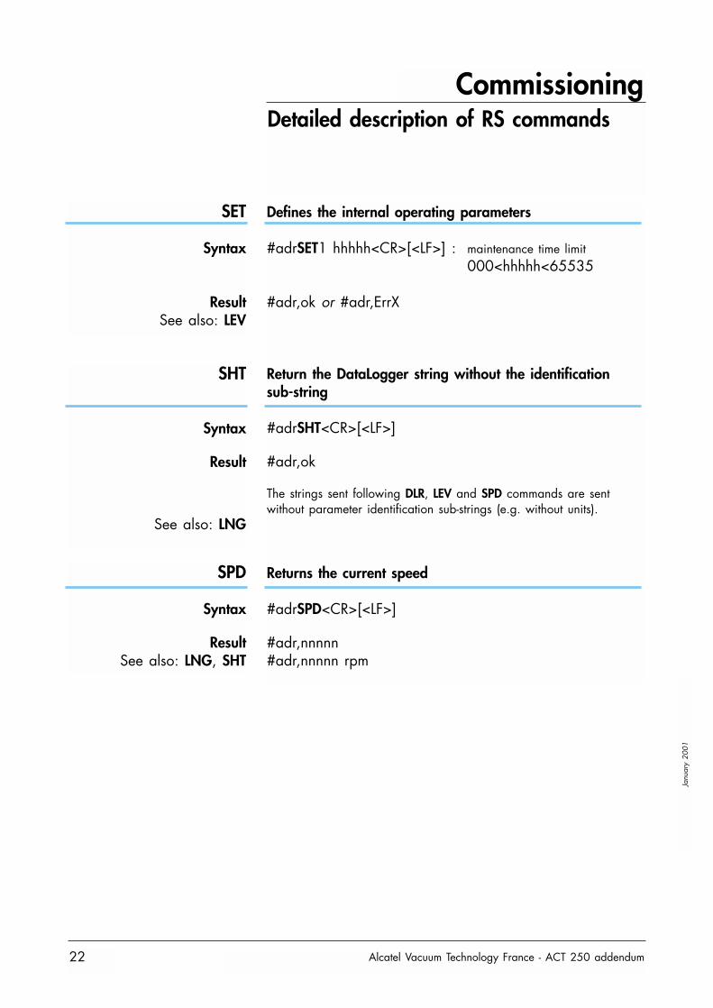
Defines the internal operating parameters
#adrSET1 hhhhh<CR>[<LF>] : maintenance time limit000<hhhhh<65535
#adr,ok or #adr,ErrX
Return the DataLogger string without the identificationsub-string
#adrSHT<CR>[<LF>]
#adr,ok
The strings sent following DLR, LEV and SPD commands are sentwithout parameter identification sub-strings (e.g. without units).
Returns the current speed
#adrSPD<CR>[<LF>]
#adr,nnnnn#adr,nnnnn rpm
Commissioning
Alcatel Vacuum Technology France - ACT 250 addendum 23
Janu
ary
2001
Detailed description of RS commands
STA
Syntax
Result
TMP
Syntax
Result
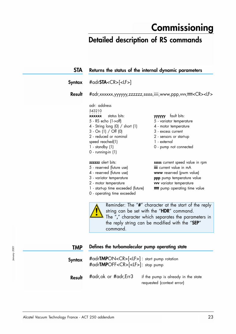
Returns the status of the internal dynamic parameters
#adrSTA<CR>[<LF>]
#adr,xxxxxx,yyyyyy,zzzzzz,sssss,iiii,www,ppp,vvv,ttttt<CR><LF>
adr: address543210xxxxxx status bits: yyyyyy fault bits:5 - RS echo (1->off) 5 - variator temperature4 - String long (0) / short (1) 4 - motor temperature3 - On (1) / Off (0) 3 - excess current2 - reduced or nominal 2 - sensors or start-upspeed reached(1) 1 - external1 - standby (1) 0 - pump not connected0 - running-in (1)
zzzzzz alert bits: sssss current speed value in rpm5 - reserved (future use) iiii current value in mA4 - reserved (future use) www reserved (pwm value)3 - variator temperature ppp pump temperature value2 - motor temperature vvv variator temperature1 - start-up time exceeded (future) ttttt pump operating time value0 - operating time exceeded
Reminder: The “#” character at the start of the replystring can be set with the “HDR” command.The “,” character which separates the parameters inthe reply string can be modified with the “SEP”command.
Defines the turbomolecular pump operating state
#adrTMPON<CR>[<LF>] : start pump rotation#adrTMPOFF<CR>[<LF>]: stop pump
#adr,ok or #adr,Err3 if the pump is already in the staterequested (context error)
Use
Alcatel Vacuum Technology France - ACT 250 addendum24
Janu
ary
2001
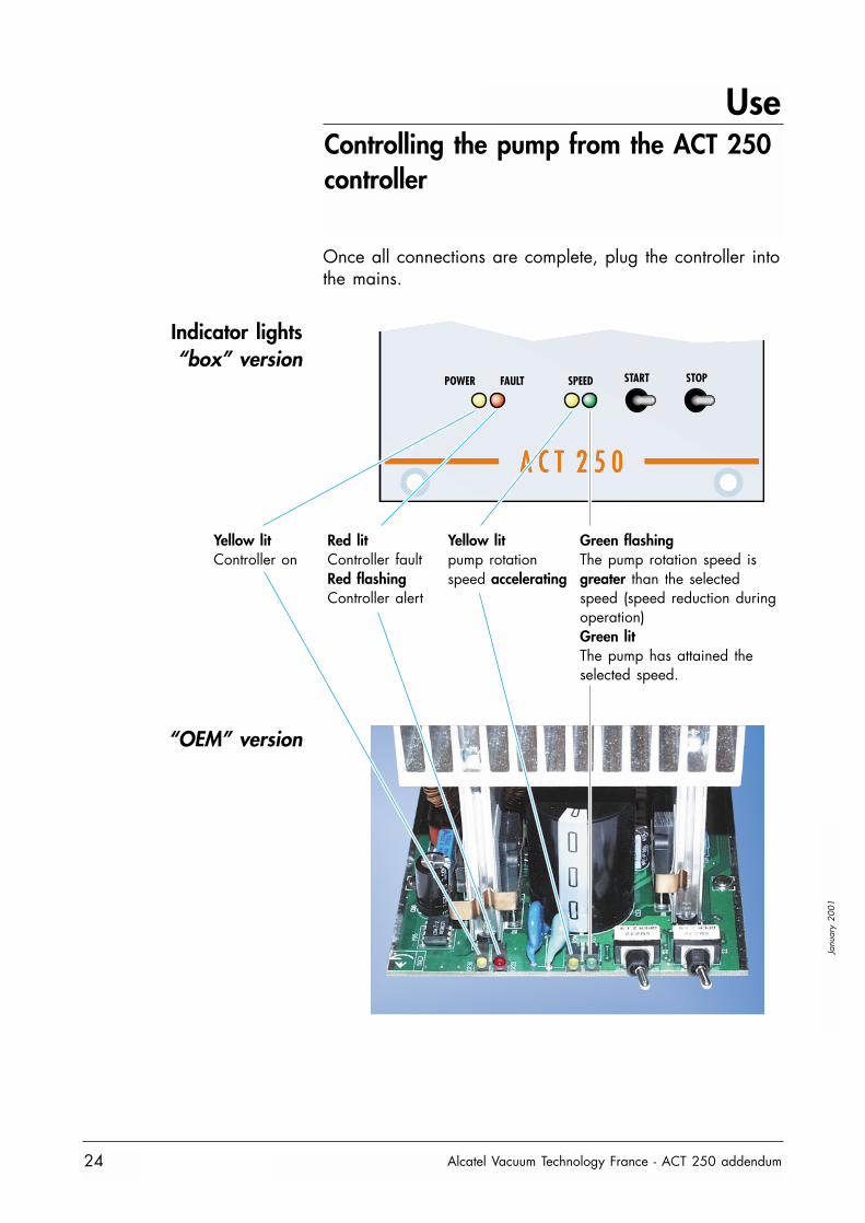
Controlling the pump from the ACT 250controller
Once all connections are complete, plug the controller intothe mains.
A C T 2 5 0A C T 2 5 0
POWER FAULT SPEED START STOP
Indicator lights“box” version
“OEM” version
Yellow litController on
Red litController faultRed flashingController alert
Yellow litpump rotationspeed accelerating
Green flashingThe pump rotation speed isgreater than the selectedspeed (speed reduction duringoperation)Green litThe pump has attained theselected speed.
Use
Alcatel Vacuum Technology France - ACT 250 addendum 25
Janu
ary
2001
Controlling the pump from the ACT 250controller
START
STOP
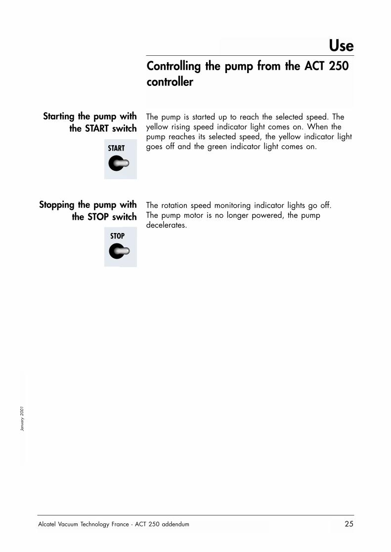
Starting the pump withthe START switch
Stopping the pump withthe STOP switch
The pump is started up to reach the selected speed. Theyellow rising speed indicator light comes on. When thepump reaches its selected speed, the yellow indicator lightgoes off and the green indicator light comes on.
The rotation speed monitoring indicator lights go off.The pump motor is no longer powered, the pumpdecelerates.
Use
Alcatel Vacuum Technology France - ACT 250 addendum26
Janu
ary
2001
Controller functions
Precautions
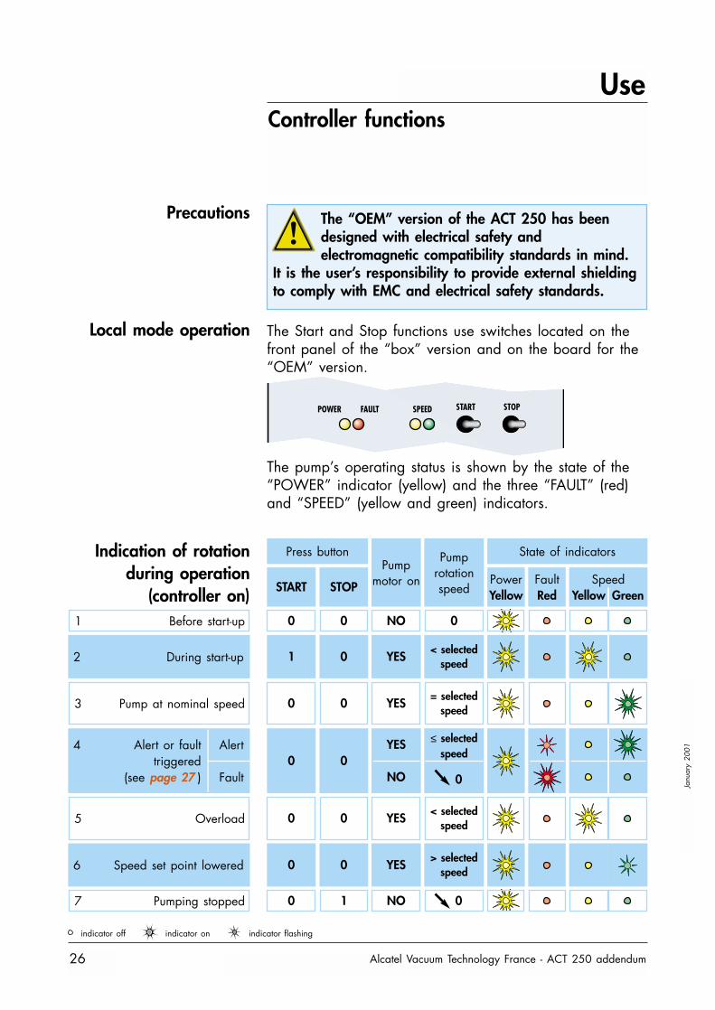
Local mode operation The Start and Stop functions use switches located on thefront panel of the “box” version and on the board for the“OEM” version.
The “OEM” version of the ACT 250 has beendesigned with electrical safety andelectromagnetic compatibility standards in mind.
It is the user’s responsibility to provide external shieldingto comply with EMC and electrical safety standards.
POWER FAULT SPEED START STOP
The pump’s operating status is shown by the state of the“POWER” indicator (yellow) and the three “FAULT” (red)and “SPEED” (yellow and green) indicators.
Indication of rotationduring operation
(controller on)
Pumpmotor on
Pumprotationspeed
State of indicators
PowerYellow
FaultRed
SpeedYellow Green
Press button
START STOP
1 Before start-up
2 During start-up
3 Pump at nominal speed
5 Overload
7 Pumping stopped
0
1
0
0
0
0
0
0
0
1
NO
YES
YES
YES
NO
0
< selectedspeed
= selectedspeed
< selectedspeed
0
6 Speed set point lowered 0 0 YES > selectedspeed
indicator off indicator on indicator flashing
4 Alert
Fault
Alert or faulttriggered
(see page 27 )0 0
YES
NO
≤ selectedspeed
0
Use
Alcatel Vacuum Technology France - ACT 250 addendum 27
Janu
ary
2001
Controller functions
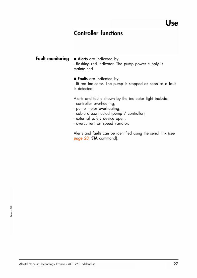
Fault monitoring ■ Alerts are indicated by:- flashing red indicator. The pump power supply ismaintained.
■ Faults are indicated by:- lit red indicator. The pump is stopped as soon as a faultis detected.
Alerts and faults shown by the indicator light include:- controller overheating,- pump motor overheating,- cable disconnected (pump / controller)- external safety device open,- overcurrent on speed variator.
Alerts and faults can be identified using the serial link (seepage 23, STA command).
FranceAlcatel Vacuum Technology - France98, avenue de Brogny - BP 206974009 ANNECY - CedexTel : (33) 4 50 65 77 77Fax : (33) 4 50 65 77 89
GermanyAlcatel Hochvakuum Technik GmbHAm Kreuzeck 10D – 97877 WERTHEIMTel: (49) 9342 96100Fax: (49) 9342 961030
ItalyAlcatel Vacuum Systems S.p.AVia Trento, 3020059 VIMERCATE (MI)Tel : (39) 039 686 3855Fax : (39) 039 667 125
JapanAlcatel Japan LTD13 fl. Dai Tokyo - Kasai Shinjuku bldg3 - 25 - 3 - Yoyogi, Shibuya - kuTOKYO 1510053 - JAPANTel : (81) 3 5302 4350Fax : (81) 3 5302 4332
KoreaAlcatel Vacuum Technology Korea5th Floor, Sunghyun B/D10-5, Karak-Dong, Songpa-KuSeoul - SOUTH KOREATel : (82) 2 409 6277Fax : (82) 2 409 6279
United KingdomAlcatel Vacuum Technology UK Ltd8 Bain SquareKirkton CampusLivingstone - WEST LOTHIANEH - 547 DQ - SCOTLANDUnited KingdomTel. (44) 1 506 418 000 Fax. (44) 1 506 418 002
USAAlcatel Vacuum Products67 Sharp StreetHINGHAM, MA. 02043USATel :1(781) 331 4200Fax :1(781) 331 4230
Alcatel Vacuum Technology - France - 98, avenue de Brogny - BP 2069 - 74009 ANNECY Cedex FranceTel. (33) 4 50 65 77 77 - Fax (33) 4 50 65 77 89 - Telex 385 153 F
Web site: www.alcatel.com
Publ
icat
ion:
Alc
atel
- Re
aliz
atio
n: A
XESS
(33)
4 7
5 42
35
90 -
Editi
on 0
1 - J
anua
ry 2
001