Embed Size (px)
Citation preview

T L S
C M P N E N T S CCCCCCCCCCCCCCC M
P R C E D U R E S
B A L L I S T I C S
Jean-Pierre BEURTHERETFreddy DRUBIGNY
CARTRIDGE HANDLOADING

JP
B 2
018 FD
V I
TABLE OF CONTENTS
FOREWORD IIIWhy handloading ? III
SPECIAL THANKS V
SECURITY RULES 1About handloading 1
Rules to enforce: 1As general rules in the fi eld of shooting sports 2
MEASUREMENT UNITS 5Length 5Mass 5Pressure 6Temperature 6The minute of angle (MOA) 6
THE METALLIC CARTRIDGE 9The evolution of fi rearms 9The pinfi re cartridge 14The rimfi re and centerfi re cartridges 14
CARTRIDGES DESIGNATION 17
THE CASE 21Security rules 21Case manufacturing 21Functions of the case 23
Structure of the case 23The neck 23The head 24The body 24
Types of cases 24Rimmed cases 25Semi rimmed cases 25Rimless cases 26Belted cases 26Rebated rim cases 27
History 27
THE BULLET 35The ogives shapes 35
Tangent Ogive 38
Secant Ogive 39Hybrid ogive 40
Lead bullets 40Lead bullet casting 41
The metal 41Melting gear 44Melting and casting 45Sizing 47
Copper plated lead bullets 48Jacketed bullets 48The monolithic bullets 52The bullet selection 53Using the molybdenum disulfi de (MoS2) on jacketed bullets 53
THE PRIMERS 57Security rules 57Historical 57Berdan primer 57Boxer primer 57Boxer primer types 59
TO START OUT 63The essential reloading tools 63The standard reloading process 64
THE PRESS 67Where it all began 67Bench presses 70
1 - The single station press 702 - The turret press 733 - The progressive press 74
WEIGHING AND MEASURING THE POWDER 77Security rules 77The scales 78
The balance scales 78The electronic scales 82The automatic scales 84The standard masses 88
The powder measures 88Using a powder measure 90
JP
B 2
018 FD
V I I
Table of contents
THE RELOADING TOOLS 93The tools of the trade, except dies 93
The loading tray 93The caliper 93The case lube pad 94The neck brush 94The case trimmer 94The burring tool 95The powder funnel 95The primer fl ip tray 95The comparator and its stand 96The borescope 96The tools to remove the primer crimp (swager or reamer) 97The primer pocket uniformer 97The primer pocket cleaner 98The fl ash hole reamer 98The Lyman kit 99The trim die 100The case neck concentricity gauges 100The neck wall thickness gauges 101The case length gauges 103The universal decap die 105The headspace gauges 105The cartridge overall length gauges for a given fi rearm and a given bullet 105The cartridge concentricity gauges 105The impact bullet puller and the collet bullet puller 105
The reloading dies 106Set for straight wall cases 106Set for conical or bottleneck cases 106Small-base full length sizing dies 108The die lock rings 108
SORTING THE CASES TO RELOAD 111
STANDARD RESIZING OF THE CASE 117Case lubrication before sizing 117Case resizing 118
Preliminary remarks 118The decapping rod 119The standard setting of the full length sizer die 120
Steel sizing dies 120Carbide sizing dies 121
THE HEADSPACE 123For a rimless straight wall case 124For a rimmed or semi rimmed case 124For a belted case 124For a rimless bottleneck case 125
Examples of the relationship between the chamber and case headspaces 125If the case headspace is greater than the chamber headspace 127If the case headspace is shorter than the chamber headspace 128Checking the chamber headspace 129Checking the case headspace 130
1 - The RCBS Precision Mic 1302 - The Hornady tool 1323 - The Wilson gauges 1334 - The sticker 135
CASE RESIZING ADVANCED TECHNIQUES 137Full length external resizing of straight wall, conical or slightly bottleneck cases 137
Steel sizing die 137Carbide sizing die 140
Full length external resizing of rimmed, semi rimmed or belted bottleneck cases (steel sizing die) 141Full length external resizing of rimless or rebated rim bottleneck cases (steel die) 142
CASE NECK RESIZING 147Conical or bottleneck cases 147
Neck resizing only 148Straight wall cases 149Why neck size only 151Partial resizing with a full length resizing die 151
NECK ANNEALING AND THINNING DOWN 153The neck annealing 153
Theoretical considerations 153When annealing the necks ? 153The method 154
1 - With molten lead 1542 - With a propane torch 154
Thinning down the neck 1551 - Neck reaming before resizing 1562 - Neck reaming during resizing 1563 - Neck turning after resizing: 157
REMOVING A STUCK CASE FROM A SIZING DIE 161
CASE CLEANING 165Mechanical means 166Electronic means 167

CARTRIDGE HANDLOADING J
PB
2018 F
D V I I I
CASE PRIMING 171Hand priming tools 172Bench priming tools 173Primer seating 173Decapping spent primers 176Decapping live primers 176
THE POWDER 179Security rules 179The origins 180The vivacity 181
Reload Swiss Burning Rate Chart 182Vectan Burning Rate Chart 183Vihtavuori Burning Rate Chart 184The relative vivacity range 186
Reduced loads 188Problems which would be linked to the use of reduced charges of slow powders 188Problems which would be linked to the use of reduced loads of fast powders 189What can we say ? 189Reduced loads of fast powders for lead bullets in bottleneck case cartridges 189
The chronograph, an essential tool 191Presentation 191Functioning 192Possible uses 192
With air guns 192With manufactured ammunitions 192With reloaded centerfi re cartridges 192With antique fi rearms 193For smooth-bore fi rearms 193Materials resistance tests 193Distance from the barrel muzzle 193
Developing a powder load 193Basic procedure 193
Reloading cartridges for a given fi rearm, the caliber of which is included in the load data of the powder manufacturer 193Bullet selection 194Powder selection 194The conduct of the tests 195
Gas operated semi-automatic fi rearms: 196Infl uence of the temperature 196
Specifi c examples 196Example 1 196
Reloading of a cartridge referenced in the load data 196
Example 2 197The selected powder for a given caliber does not appear in the load data 197
Example 3 199Reloading of a cartridge not referenced in the load data 199
CASE FILLING PROCEDURES 2031 - Using the scale or the powder measure (procedure 1) 2042 - Using the scale or the powder measure (procedure 2) 2053 - Using the powder measure only (procedure 3) 205Additional check 206
BULLET SEATING 209Methods for determining the maximum cartridge overall length (OAL) for a given bullet 210
1 - The cleaning rod 2102 - The RCBS MIC 2123 - The Hornady OAL gauge 213
The seating dies 218Bullet crimping 220
Roll crimp 221Taper crimp 222Factory crimp 223Profi le crimp 224
Use of the seating and crimping dies 224Die setting to seat the bullet without crimping 224Die setting to seat and crimp the bulletin one step 224Die setting to seat and crimp the bullet in two steps 225
Checking the cartridge concentricity 225The RCBS Case Master 225The Hornady Lock-N-Load Concentricity Tool 225
PRESSURE EXTERNAL SIGNS 227
CARTRIDGES DISASSEMBLING 235First method: the impact bullet puller 236Second method: the collet bullet puller 238Third method: the locking pliers 239Fourth method: the specialized tool 239
CASES CONVERSIONS 241Conversion of 223 Remington into 7 TCU by fi re forming 241Conversion of 5,6 x 50 R Magnum into 357 Super Mag (357 Maximum) 242Conversion of 30-30 WCF into 32-40 243Conversion of 308 Winchester into 7-08 243Conversion of 22 Hornet into 22 K Hornet 244Conversion of 30-30 WCF into 357 Herrett 244Conversion of 30-30 WCF into 30 Herrett 244Shoulder blow out of a bottleneck case 244Conversion of 357 Maximum or 5,6 x 50 R Magnum into 7,62 x 38 R Nagant 246Conversion of 45 Colt into 455 Webley 249

JP
B 2
018 FD
I X
Table of contents
BARRELS AND CHAMBERS CASTINGS 253CerrosafeTM instructions (from a Brownells® document) 253
Chamber casting 254Removing a broken case from the chamber 255Warning 255Note on casting measurements 255
BLACK POWDER CARTRIDGES 257Reloading black powder cartridges 258
BALLISTICS 261Why barrels are rifl ed ? 262Stabilization of a bullet in fl ight 263The movements of the bullet 264
Yaw 264Pitch 264Precession 264Nutation 264
Barrel rifl ing 265Measuring the twist rate 266Internal ballistics 269
The Greenhill formula 270Miller’s formula 273The recoil 276The barrel vibration 277
External ballistics 279Intermediate or transitional ballistics 279The trajectory of the bullet 282
The forces at play 2821 - The effects of gravity and drag 2822 - The effects of the wind 2863 - The Magnus effect 2864 - The spin drift 2875 - The Coriolis effect 2876 - The Eötvös effect 289
Other infl uential factors 2891 - The ballistic coeffi cient 289
1.1 - The drag coeffi cient 2891.2 - The sectional density 2901.3 - The form factor 2901.4 - The standard models 2911.5 - The sound barrier 2971.6 - Infl uence of BC on trajectory 2991.7 - Maximum point blank range (MPBR) 305
2 - The shooting angle 3053 - The altitude 3084 - The atmospheric pressure 3085 - The temperature 308
When a bullet falls back 308About ricochets 310Terminal ballistics 310
Test N° 1 311Test N° 2 312
Test N° 3 313Test N° 4 314Test N° 5 315Test N° 6 316Test N° 7 317Test N° 8 318
ABOUT THE 22 LONG RIFLE 321How to select the ammunition 321Cartridges sorting 321The barrel length 322
THE STANDARD DEVIATION 327
SHOT GROUPING ANALYSIS 3311 - The H + W 3312 - The extreme spread 331
SECURITY 335Unusual Accidents 335Shooting ranges design 336
Preventing a bullet direct exit 336Ricochets management 339
Eye and hearing protections for the shooter and bystanders 339
The shooter must wear eye protection 339The shooter must wear hearing protection 339
Lead 341Recommendations to shooters 343At the range 343
FUNCTIONING OF SEMI-AUTOMATICAND AUTOMATIC FIREARMS 345Firing from an open bolt 346Firing from a closed bolt 346Blowback fi rearms 346
Delayed blowback fi rearms 347Locked breech fi rearms 347
Long recoil operation 347Short recoil operation 347Gas operated fi rearms 348
BIBLIOGRAPHY 351
NOTES 354
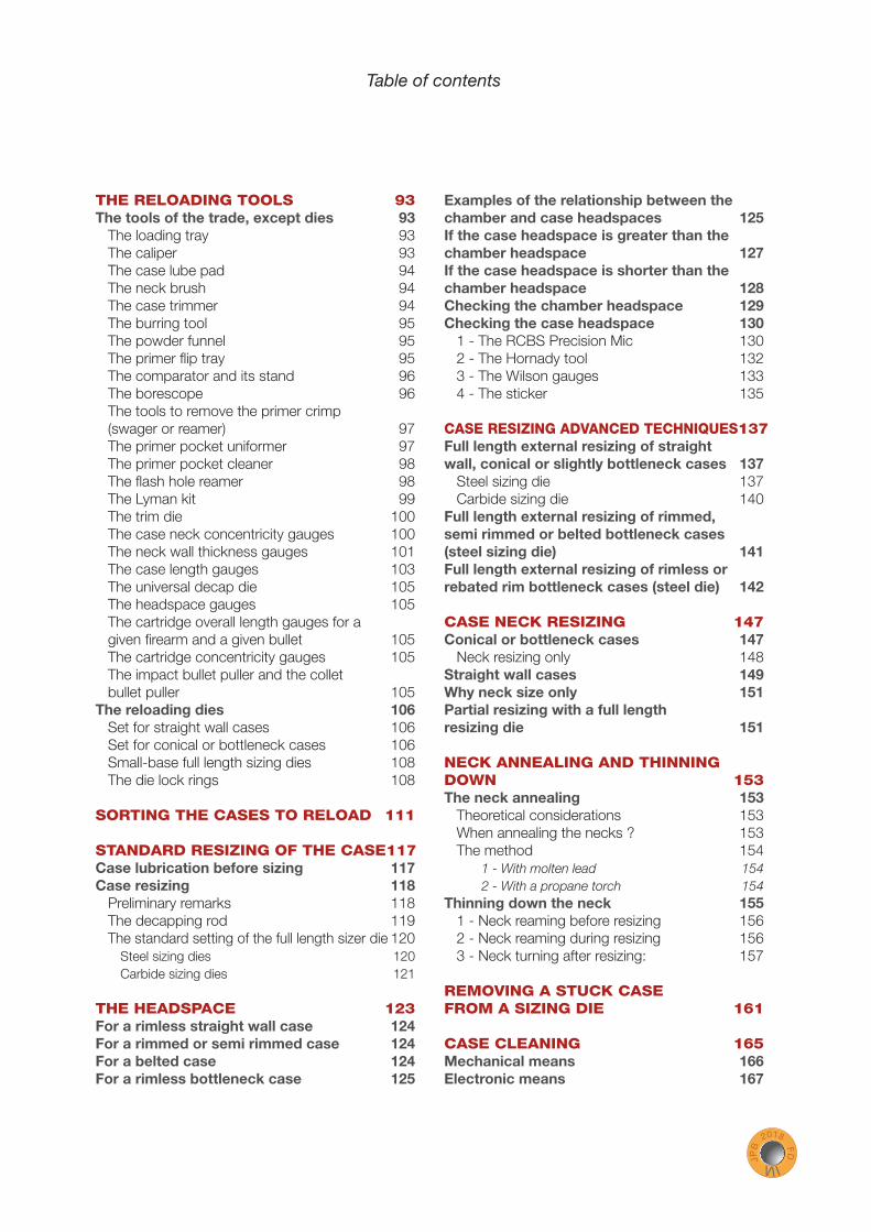
Soft point bullets. The lead core is apparent at the tip of the bullet.
Full metal jacket bullets. The lead core is apparent at the base of the bullet.
Example of a totally jacketed bullet. This is the sectional view of a Winchester Silvertip bullet. The jacket of the body and the base of the bullet is brass and the jacket of the nose is aluminum. It is a controlled expansion hunting bullet.
JP
B 2
018 FD
4 9
The bullet
Some bullets are completely enclosed by a jacket made of at least two parts, where the lead core is not apparent at all. These include, but are not limited to, some composite hunting bullets. The aim is to control expansion and mass conservation at the im-pact.
To detect a steel jacket, use a magnet. If the magnet sticks to the bullet, it is steel. However, if the bullet has a steel core, as is often the case with Russian calibers surplus ammunition, the magnet will stick too. With the magnet, it is impossible to know if we are dealing with a standard bullet with a lead core and a mild steel jacket, or if it is a steel core projectile with probably also a mild steel jacket . To be sure, it is necessary to disassemble a cartridge and examine the bullet. A steel core is visible at the base of the bullet.
In some cases, the bullet may be color-coded.
It is important to know if a bullet contains a steel core.Using brass or mild steel jacketed bullets makes no difference in a standard shooting range. The mild steel jackets are not harder than the brass jackets on the bullet baffl es.It is different with a steel core, even if these standard Russian surplus bullets are not true armor piercing bullets.
True armor piercing bullets have a core made of hardened steel or of another metal having the de-sired hardness (tungsten alloy for example). The sur-plus bullets quoted here have a mild steel core. This metal was chosen to save lead. They are not labeled «armor piercing» from the military standpoint. But even if their performances are inferior to true armor piercings, the installations of the shooting ranges are generally not designed to properly stop them.
Sample of jacketed bullets of different calibers.
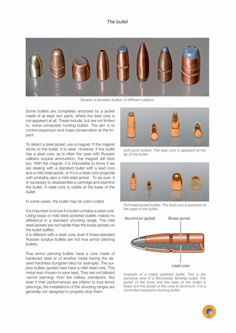
Lyman Crusher 2Redding Big Boss II
Pho
tos
cour
tesy
of R
edd
ing
Pho
tos
cour
tesy
of L
yman
CARTRIDGE HANDLOADING J
PB
2018 F
D 7 2
Sketch of a conventional single station press, fi tted with a priming system. The lever is shown in the intermediate position, half-lowered.

JP
B 2
018 FD
1 2 7
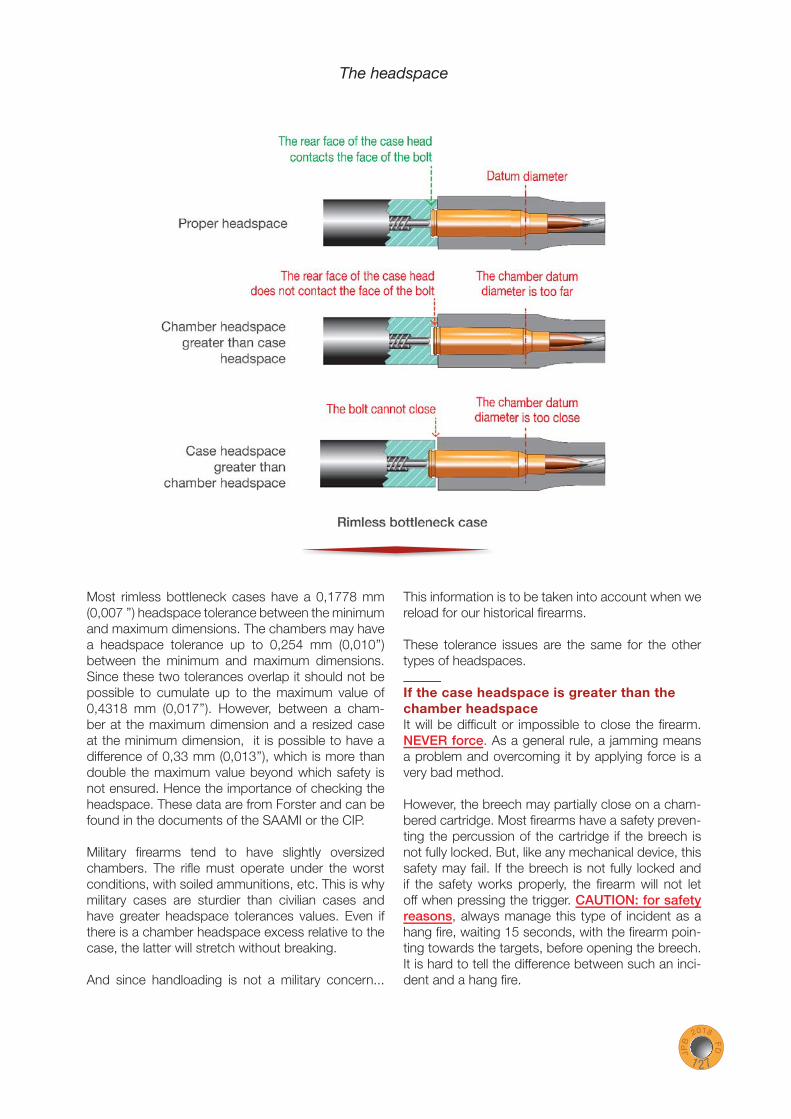
The headspace
Most rimless bottleneck cases have a 0,1778 mm (0,007 ’’) headspace tolerance between the minimum and maximum dimensions. The chambers may have a headspace tolerance up to 0,254 mm (0,010’’) between the minimum and maximum dimensions. Since these two tolerances overlap it should not be possible to cumulate up to the maximum value of 0,4318 mm (0,017’’). However, between a cham-ber at the maximum dimension and a resized case at the minimum dimension, it is possible to have a difference of 0,33 mm (0,013’’), which is more than double the maximum value beyond which safety is not ensured. Hence the importance of checking the headspace. These data are from Forster and can be found in the documents of the SAAMI or the CIP.
Military fi rearms tend to have slightly oversized chambers. The rifl e must operate under the worst conditions, with soiled ammunitions, etc. This is why military cases are sturdier than civilian cases and have greater headspace tolerances values. Even if there is a chamber headspace excess relative to the case, the latter will stretch without breaking.
And since handloading is not a military concern...
This information is to be taken into account when we reload for our historical fi rearms.
These tolerance issues are the same for the other types of headspaces.
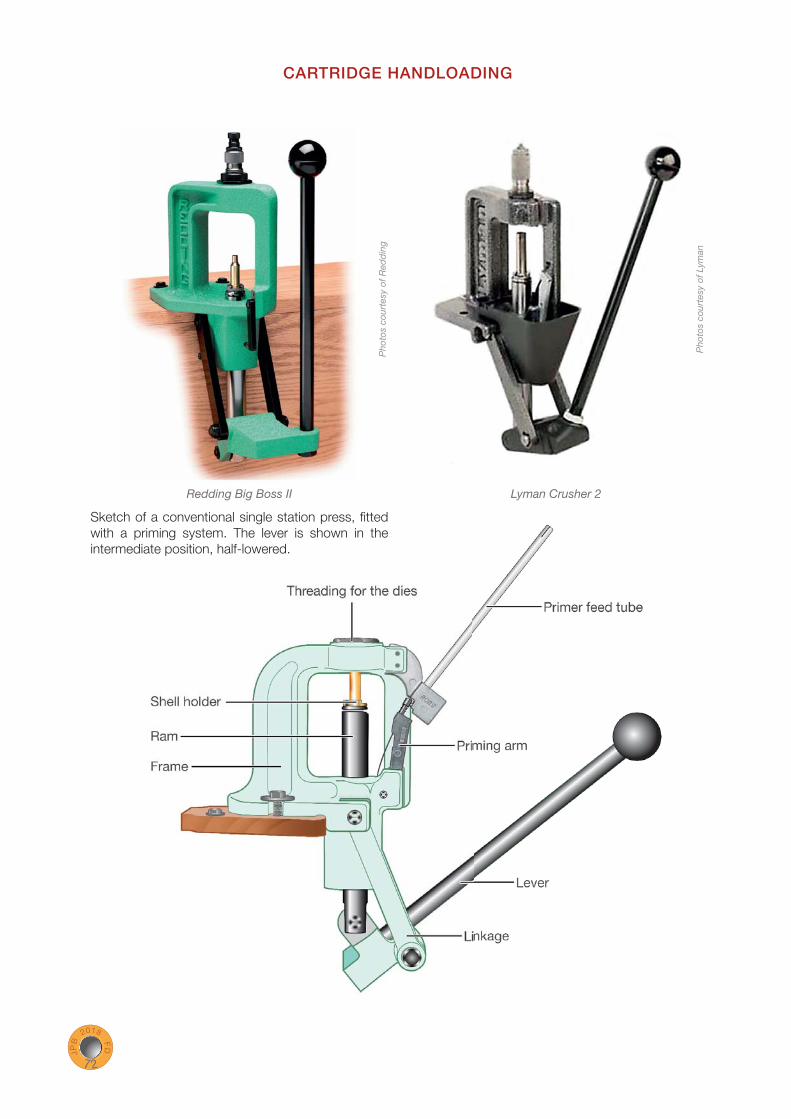
If the case headspace is greater than the chamber headspaceIt will be diffi cult or impossible to close the fi rearm. NEVER force. As a general rule, a jamming means a problem and overcoming it by applying force is a very bad method.
However, the breech may partially close on a cham-bered cartridge. Most fi rearms have a safety preven-ting the percussion of the cartridge if the breech is not fully locked. But, like any mechanical device, this safety may fail. If the breech is not fully locked and if the safety works properly, the fi rearm will not let off when pressing the trigger. CAUTION: for safety reasons, always manage this type of incident as a hang fi re, waiting 15 seconds, with the fi rearm poin-ting towards the targets, before opening the breech. It is hard to tell the difference between such an inci-dent and a hang fi re.

Full length external resizing of a rimmed straight wall case (357 Magnum).
1 3 71 3 7
JP
B 2
018 FD
1 3 7
CASE RESIZING ADVANCED TECHNIQUES
The three paragraphs of this chapter look alike, so it is important to tell them apart.
The fi rst paragraph deals with the full length external resizing of straight wall, conical or slightly bottleneck cases, regardless of the shape of their head.
The second paragraph deals with the full length external resizing of rimmed, semi rimmed or belted bottleneck cases.
The third paragraph deals with the full length external resizing of rimless or rebated rim bottleneck cases.
Full length external resizing of straight wall, conical or slightly bottleneck cases
Steel sizing dieThe sizing die will be set on the press in a standard fashion.Slightly bottleneck cases (44-40 WCF, 22 Hornet, etc.) can also be resized in this way. However, we will see in the next paragraph that a more sophisticated procedure is possible.

Forster neck reamer
The reamer set on the case trimmer.
CARTRIDGE HANDLOADING J
PB
2018 F
D 1 5 6
1 - Neck reaming before resizingThe inside of the neck is reamed to reduce its thickness. This operation is performed on a case trimmer fi tted to do it. The reamer is set in place of the case trimmer pilot. The reamer diameter is chosen according to the desired neck tension. For some case conversions, it may be necessary to ream unfi red cases.Some people put forward two things against this method:
› The reamer may not exactly center into the neck. The thickness of the neck will not necessarily be uniform around the whole cir-cumference.
› The quantity of brass removed is determined by the reamer diameter.
In practice, this procedure works rather well, but it is true that the neck thickness is sometimes thinner on one side than the other after the operation.
2 - Neck reaming during resizingThis technique is used for a case conversion, when the neck diameter is heavily shrunk or when the new neck is located at a place where the walls of the original case are thick. The amount of brass to be removed is important. RCBS and some other ma-nufacturers market a specifi c full length resizing die, including a reamer used with a T handle tap wrench or a drill. The specifi c resizing die fi rmly holds the case and preserves the external dimensions of the neck during reaming. With this method, the reamer enters concentric into the neck.
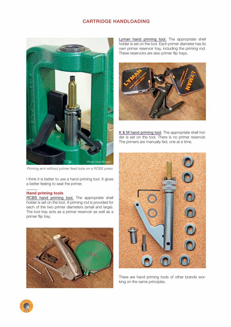
Priming arm without primer feed tube on a RCBS press
CARTRIDGE HANDLOADING J
PB
2018 F
D 1 7 2
I think it is better to use a hand priming tool. It gives a better feeling to seat the primer.
Hand priming toolsRCBS hand priming tool. The appropriate shell holder is set on the tool. A priming rod is provided for each of the two primer diameters (small and large). The tool tray acts as a primer reservoir as well as a primer fl ip tray.
Lyman hand priming tool. The appropriate shell holder is set on the tool. Each primer diameter has its own primer reservoir tray, including the priming rod. These reservoirs are also primer fl ip trays.
K & M hand priming tool. The appropriate shell hol-der is set on the tool. There is no primer reservoir. The primers are manually fed, one at a time.
There are hand priming tools of other brands wor-king on the same principles.
PhoPhoPhoPh to to o YveYvYves Ss Ss trutrutruuuuuurugegengegen

Some Weatherby calibers.From left to right: 224, 240, 257, 270, 7 mm, 300, 340, 378, 460.
2 0 92 0 9
JP
B 2
018 FD
2 0 9
BULLET SEATING
Manufacturer’s data indicate a maximum cartridge length not to be exceeded. It is a standard measure designed to ensure that any cartridge of a given caliber operates correctly in any fi rearm chambered for that cartridge. But this does not necessarily cor-respond to the optimum cartridge length for a specifi c fi rearm.This optimum cartridge length depends on:
› The shape and length of the bullet. › Where the beginning of the rifl ing is located in the barrel (free bore length). › The distance at which the shooter wants to position the beginning of the bullet’s bearing surface in relation to the barrel rifl ing.
The bullet can be seated in the case in order to have more or less free travel before reaching the rifl ing, or even no free travel at all in order to contact the rifl ing when cham-bered. For a given powder load, the pressure will be higher with a bullet contacting the rifl ing, compared to a bullet having some free travel before reaching the rifl ing, even if, in this case, the deeper bullet seating reduces slightly the volume available for the powder.The chambers of the high-capacity magnum calibers are designed so that the bullet has a longer than average free travel before reaching the rifl ing. This is especially true for the Weatherby rifl e calibers. Weatherby manufactured cartridges are loaded for maximum performance and the free bore of nearly 10 millimeters of the chambers in which they are used is designed to handle the pressure generated.

Taken apart: the body, the bullet guide, the seating plug and the micrometer.
A special shell holder which gets inside the body is provided.
RCBS 222 Remington precision seating die with a bullet seating micrometer. Unlike the other dies where the bullet is introduced from the bottom, the bullet is introduced through a side window built into the body.
Redding 223 Remington seating die.
Cross section of a seating die for bottleneck cases.
Redding 6 BR Norma precision seating die with a bullet seating micrometer.
The same one taken apart. From left to right: the body, the bullet guide, the bullet guide return spring, the seating plug, the micrometer. This tool does not crimp.
JP
B 2
018 FD
2 1 9
Bullet seating
With all these dies, the bullet seating depth is ad-justed by screwing more or less the seating plug. The concentricity of the bullet in relation to the case can be improved by seating the bullet in two steps. The bullet is halfway seated. The cartridge is remo-ved from the die by raising the press lever, and then manually rotated half a turn in the shell holder. The press lever is lowered to complete the seating of the bullet. Watch your fi ngers. A faulty timing of the right and left hand during the second ram stroke may leave fi ngers between the shell holder and the die, and then...

Strain gauges glued to a Contender barrel
JP
B 2
018 FD
2 2 9
Pressure external signs
The strain gauge is used to determine a pressure from the instantaneous expansion of the metal of the chamber. Knowing the peak pressure of the cartridge, we can try to determine if there is a real correlation between the case head expansion and a given pressure.
Many years ago (1991 to be precise), I conducted some tests with a friend of mine. We glued strain gauges on T/C Contender pistol barrels chambered in 7 TCU, 30-30 WCF and 357 Magnum, to see if it was possible to evaluate the pressure of a cartridge with this technique. The gauges were connected to an electronic circuit in charge to decipher the infor-mation. Prior to the experiment, the cartridges of 30-30 WCF and 357 Magnum were fi red in a pressure barrel at the SNPE (Société Nationale des Poudres et Explosifs; National Society of Powders and Ex-plosives) in order to calibrate the gauges and have reliable comparison means. The SNPE did not own a 7 TCU pressure barrel, so the only indication we had for this cartridge was the peak pressure given by the manufacturer (the GIAT now Nexter). If my memories are correct, the pressure barrel used was of the cru-sher type. This notion is explained at the end of this chapter.
The tests were performed with 5, 8 or 10 cartridges. The Vectan TU3 used in the 30-30 WCF is no
longer manufactured. The Vectan SP3 used in the 357 Magnum is still in production.
The standard deviation quantifi es the dispersion of the results. I develop this notion at the end of the book. Statistically, two standard deviations from the mean account for 95% of the values.
Example with a mean of 2 000 and a standard deviation of 100. Statistically speaking, 95% of the values lie between 1 800 (mean minus two stan-dard deviations) and 2 200 (mean plus two standard deviations).
The smaller the standard deviation, the more the values are gathered around the mean, indicating that the values are consistent. To get a meaningful measurement, the sample studied must be repre-sentative of what is being measured.
The larger the sample, the more statistically signifi -cant the measurement. Here, the samples are small, and they only allow one to begin to get an idea.
7 TCU results:The pressure given by the manufacturer is 3 350 bars (48 587 psi). The gauges gave an average pres-sure of the same value with a standard deviation of 121 bars (1 755 psi).
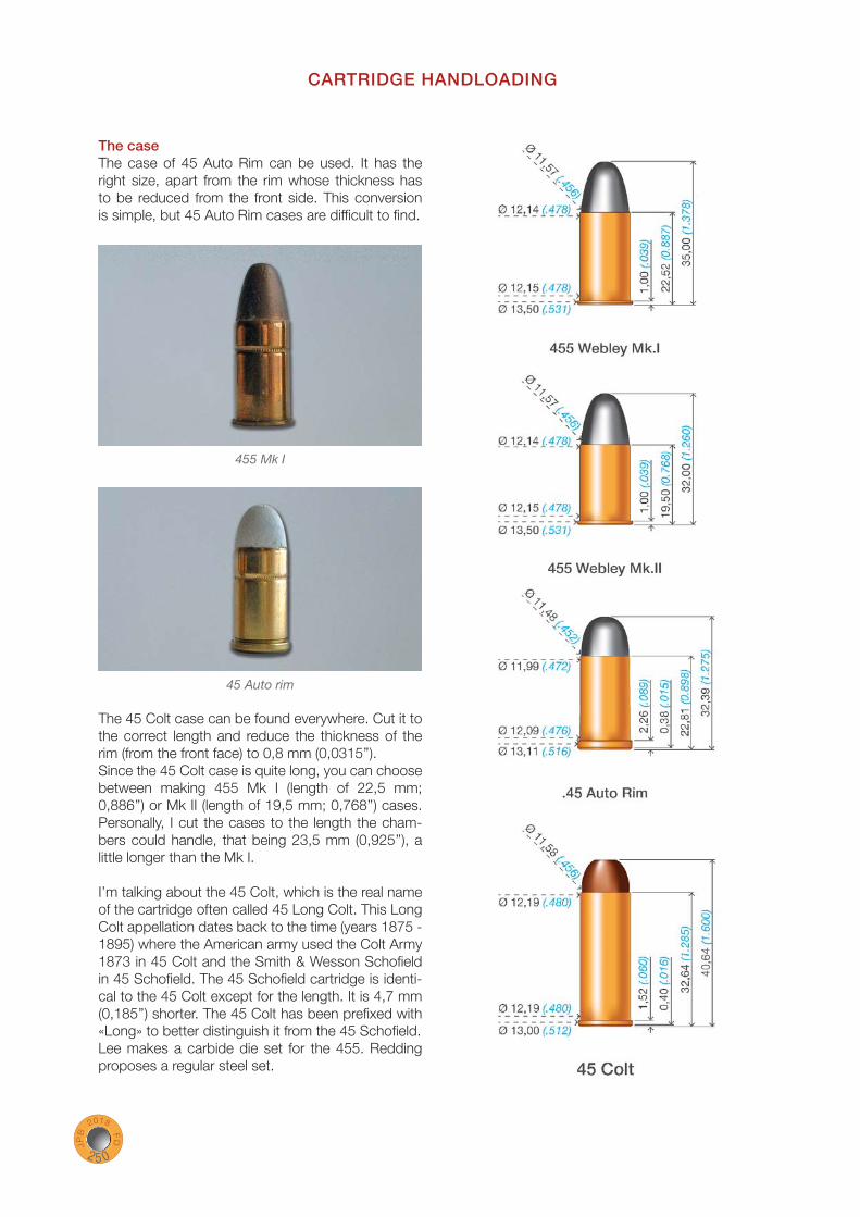
455 Mk I
45 Auto rim
CARTRIDGE HANDLOADING J
PB
2018 F
D 2 5 0
The caseThe case of 45 Auto Rim can be used. It has the right size, apart from the rim whose thickness has to be reduced from the front side. This conversion is simple, but 45 Auto Rim cases are diffi cult to fi nd.
The 45 Colt case can be found everywhere. Cut it to the correct length and reduce the thickness of the rim (from the front face) to 0,8 mm (0,0315’’).Since the 45 Colt case is quite long, you can choose between making 455 Mk I (length of 22,5 mm; 0,886’’) or Mk II (length of 19,5 mm; 0,768’’) cases. Personally, I cut the cases to the length the cham-bers could handle, that being 23,5 mm (0,925’’), a little longer than the Mk I.
I’m talking about the 45 Colt, which is the real name of the cartridge often called 45 Long Colt. This Long Colt appellation dates back to the time (years 1875 - 1895) where the American army used the Colt Army 1873 in 45 Colt and the Smith & Wesson Schofi eld in 45 Schofi eld. The 45 Schofi eld cartridge is identi-cal to the 45 Colt except for the length. It is 4,7 mm (0,185’’) shorter. The 45 Colt has been prefi xed with «Long» to better distinguish it from the 45 Schofi eld.Lee makes a carbide die set for the 455. Redding proposes a regular steel set.
CARTRIDGE HANDLOADING J
PB
2018 F
D 2 6 4
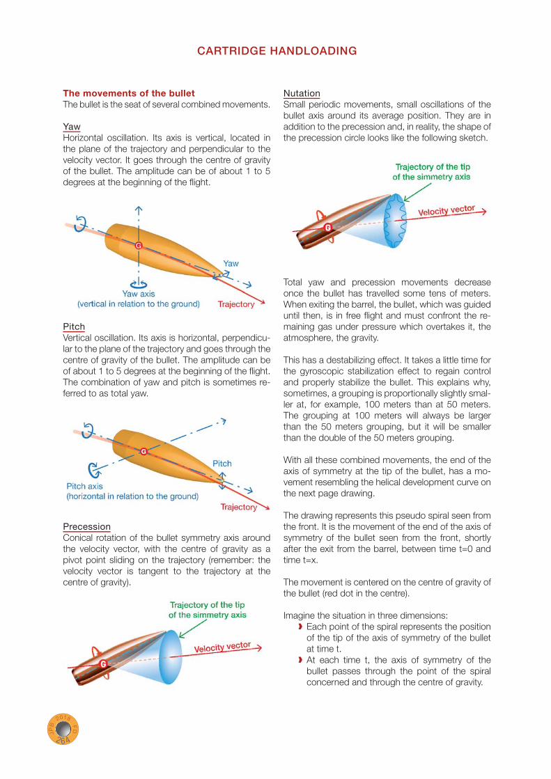
The movements of the bulletThe bullet is the seat of several combined movements.
YawHorizontal oscillation. Its axis is vertical, located in the plane of the trajectory and perpendicular to the velocity vector. It goes through the centre of gravity of the bullet. The amplitude can be of about 1 to 5 degrees at the beginning of the fl ight.
PitchVertical oscillation. Its axis is horizontal, perpendicu-lar to the plane of the trajectory and goes through the centre of gravity of the bullet. The amplitude can be of about 1 to 5 degrees at the beginning of the fl ight. The combination of yaw and pitch is sometimes re-ferred to as total yaw.
PrecessionConical rotation of the bullet symmetry axis around the velocity vector, with the centre of gravity as a pivot point sliding on the trajectory (remember: the velocity vector is tangent to the trajectory at the centre of gravity).
NutationSmall periodic movements, small oscillations of the bullet axis around its average position. They are in addition to the precession and, in reality, the shape of the precession circle looks like the following sketch.
Total yaw and precession movements decrease once the bullet has travelled some tens of meters. When exiting the barrel, the bullet, which was guided until then, is in free fl ight and must confront the re-maining gas under pressure which overtakes it, the atmosphere, the gravity.
This has a destabilizing effect. It takes a little time for the gyroscopic stabilization effect to regain control and properly stabilize the bullet. This explains why, sometimes, a grouping is proportionally slightly smal-ler at, for example, 100 meters than at 50 meters. The grouping at 100 meters will always be larger than the 50 meters grouping, but it will be smaller than the double of the 50 meters grouping.
With all these combined movements, the end of the axis of symmetry at the tip of the bullet, has a mo-vement resembling the helical development curve on the next page drawing.
The drawing represents this pseudo spiral seen from the front. It is the movement of the end of the axis of symmetry of the bullet seen from the front, shortly after the exit from the barrel, between time t=0 and time t=x.
The movement is centered on the centre of gravity of the bullet (red dot in the centre).
Imagine the situation in three dimensions:› Each point of the spiral represents the position
of the tip of the axis of symmetry of the bullet at time t.
› At each time t, the axis of symmetry of the bullet passes through the point of the spiral concerned and through the centre of gravity.

JP
B 2
018 FD
3 1 3
Ballistics
Test n° 3Materials tested (fi ve layers)Layer 1: a pine board 65 mm (2,6’’) thick, set perpendicular to the fi ring axis.Layers 2 to 5: four ordinary steel sheets (24 kg/mm²), 3 mm thick, set perpendicular to the fi ring axis and spaced 30 mm apart, with the fi rst sheet of the series set 60 mm behind the pine board.All the bullets get through the pine board.
22 Hornet: 45 grs (2,9 grams) soft point bullet V0 709 m/s (2 326 fps): stopped by sheet 1 which is bulged.55 grs (3,6 grams) full metal jacket bullet V0 619 m/s (2 031 fps): sheet 1 pierced, stopped by sheet 2 which is very bulged.
7 BR: 150 grs (9,7 grams) Match bullet V0 556 m/s (1 824 fps): sheet 1 pierced, stopped by sheet 2 which is pierced too (the bullet disintegrated while making the hole in sheet 2, sheet 3 is intact).
357 Maximum: 200 grs (13 grams) soft point bul-let V0 386 m/s (1 266 fps): stopped by sheet 1 which is pierced (the bullet disintegrated, sheet 2 is intact).
30-20: 150 grs (9,7 grams) soft point bullet V0 530 m/s (1 739 fps): sheet 1 pierced, stopped by sheet 2 which is pierced too (the bullet disintegrated, sheet 3 is intact).
44 Magnum: 240 grs (15,6 grams) soft point bullet V0 400 m/s (1 312 fps): stopped by sheet 1 which is pierced (the bullet disintegrated, sheet 2 is intact).
7x64: 154 grs (10 grams) soft point bullet V0 835 m/s (2 740 fps): sheet 1 pierced, stopped by sheet 2 which is pierced too (the bullet disintegrated, sheet 3 is intact).
243 Winchester: 80 grs (5,2 grams) soft point bullet V0 932 m/s (3 058): sheet 1 pierced, stopped by sheet 2 which is bulged.
Ordinary steel plates are effective when set in separate layers, but the impacts are destructive.

P R I C E4 9 €
ISBN 979-10-94323-22-9
w w w . e d i t i o n s - d u - p l a t e a u . f ra l a i n . p i c a r t @ e d i t i o n s - d u - p l a t e a u . f r
The author
Jean-Pierre BEURTHERET Member of the French Shooting Federation since the beginning of the 70’s, he is a competitor, practicing several shooting disciplines and more specifi cally metallic silhouette shooting, in which he won three individual champion titles (two national and one European) and one world team champion title.He has been practicing handloading for more than forty years.
The illustrator
Freddy DRUBIGNYMember of the French Shooting Federation since 1976, he won two individual champion titles (one national and one European) in metallic silhouette shooting.He worked for thirty years in an engineering and design department. This experience allowed him to shape and achieve the technical drawings of this book as well as the post processing of the photographs. He also performed the layout.
The bookThe aim of this book is to explain the subject from a different standpoint than usually found.
You will fi nd in it a brief history of the metallic cartridge and the description of its components (the primer, the case, the powder, the bullet) and of the various tools used for handloading.
The detailed description of advanced handloading procedures and die adjustments departs from the usual specialized literature and will allow the production of ammunition totally adapted to a specifi c fi rearm, using the standard reloading tables of the powder manufacturers. Cartridge conversions, ballistics, security of the shooters and on the range are not forgotten. The last chapter is devoted to a short description of the automatic and semi-automatic fi rearms operation.
This book will allow you a didactic approach into the exciting world of perpetual research which is:
« CARTRIDGE HANDLOADING »