Embed Size (px)
Citation preview


1
Electric Welded Non-alloy Steel Tubes for Cement Lined Pipes (SPAN TS 21827:PART 2:2013)
1
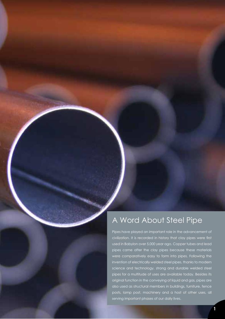
A Word About Steel Pipe Pipes have played an important role in the advancement of
civilization. It is recorded in history that clay pipes were first
used in Babylon over 5,000 year ago. Copper tubes and lead
pipes came after the clay pipes because these materials
were comparatively easy to form into pipes. Following the
invention of electrically welded steel pipes, thanks to modern
science and technology, strong and durable welded steel
pipes for a multitude of uses are available today. Besides its
original function in the conveying of liquid and gas, pipes are
also used as structural members in buildings, furniture, fence
posts, lamp post, machinery and a host of other uses, all
serving important phases of our daily lives.
1
2
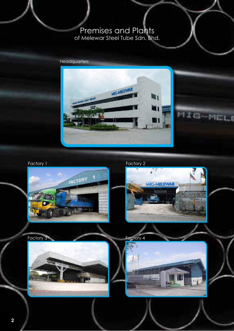
Premises and Plantsof Melewar Steel Tube Sdn. Bhd.
2
Factory 1 Factory 2
Factory 3 Factory 4
Headquarters

3
The year 1969 heralded the establishment of a Malaysian-Japanese joint venture into the steel pipe manufacturing industry with the establishment of Aurora Steel Tube Manufacturing Sdn Bhd. The Company went into production with one production line in January 1970 at its factory in Jalan Gudang, Shah Alam.
To mark the participation of Maruichi Steel Tube Ltd, Osaka, Japan in 1972, a new was adopted for the company - Maruichi MalaysiaSteel Tube Sdn Bhd.
Within a matter of 2 years the company expanded its operations; a second factory equipped with additional production lines and hot dip galvanizing facilities went into operation on a 7 acre site in Jalan Utas, Shah Alam in 1974.
In 1975 the company was converted into a public company.
The Year 1982 saw the opening of the company’s No. 3 factory at Persiaran Selangor, Shah Alam and the commencement of operation of the company’s 100% owned subsidiary, Tokyo Steel Wire Sdn Bhd, also in Shah Alam.
Maruichi Malaysia Steel Tube Bhd was listed on the Kuala Lumpur Stock Exchange in 1986. Our Corporate headquarters and the latest No. 5 factory was built at Persiaran Selangor in 1990. That same year also marked the commencement of operations of our wholly owned subsidiary, Cold Rolling Industry (Malaysia) Sdn Bhd, the first Cold Rolled Coil manufacturer in Malaysia.
Following a change in ownership, the company was renamed as Melewar Industrial Group Berhad (MIG) in November 2003. Product brand was also changed to MIG – MELEWAR.
Presently Melewar Steel Tube Sdn. Bhd. has an installed capacity of more than 18,600 tonne per month with the ability to manufacture pipes from 9mm to 400mm O.D. MIG’s products are widely used in the construction, furniture, automotive, bicycle and engineering industries. Today, after more than three decades of experience in the steel pipe industry, the brand MIG-MELEWAR spells quality, having made its name in the steel industry where its products are highly acclaimed by both local as well as international users.
3
Company Profile
4
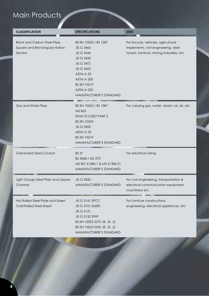
Main Products
4
CLASSIFICATION SPECIFICATIONS USES Black and Carbon Steel Pipe, BS EN 10255 / BS 1387 For bicycle, vehicles, agricultural Square and Rectangular Hollow JIS G 3466 implements, civil engineering, steel Section JIS G 3444 towers, furniture, mining industries, etc JIS G 3445 JIS G 3472 JIS G 3452 ASTM A 53 ASTM A 500 BS EN 10219 ASTM A 252 MANUFACTURER’S STANDARD Gas and Water Pipe BS EN 10255 / BS 1387 For carrying gas, water, steam, oil, air, etc MS 863 SPAN TS 21827:PART 2 BS EN 10224 JIS G 3452 ASTM A 53 BS EN 10219 MANUFACTURER’S STANDARD Galvanised Steel Conduit BS 31 For electrical wiring BS 4568 / MS 275 MS IEC 61386-1 & MS 61386-21 MANUFACTURER’S STANDARD Light Gauge Steel Plain and Lipped JIS G 3350 For civil engineering, transportation & Channel MANUFACTURER’S STANDARD electrical communication equipment, machinery etc. Hot Rolled Steel Plate and Sheet JIS G 3141 SPCC For furniture constructions, Cold Rolled Steel Sheet JIS G 3101 SS400 engineering, electrical appliances, etc JIS G 3131 JIS G 3132 SPHT BS EN 10025 S275 JR, J0, J2 BS EN 10025 S355 JR, J0, J2 MANUFACTURER’S STANDARD
5
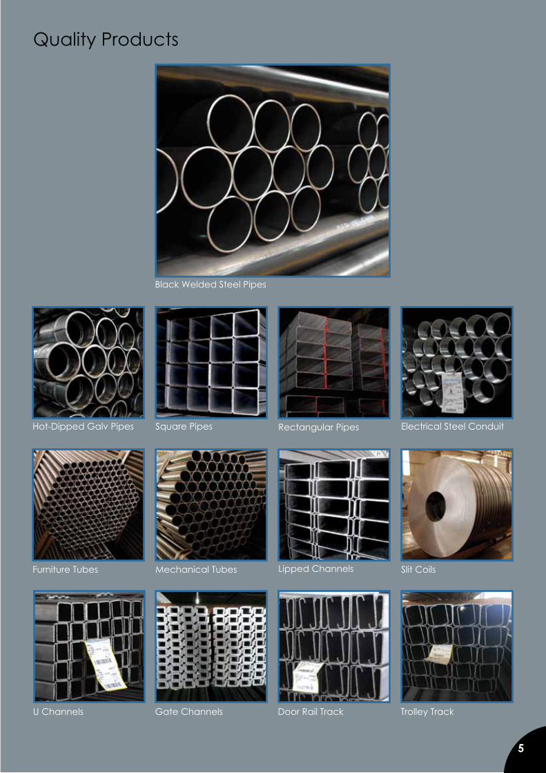
Quality Products
Black Welded Steel Pipes
Gate Channels Door Rail Track Trolley Track
5
Electrical Steel ConduitSquare PipesHot-Dipped Galv Pipes
Lipped Channels Slit Coils
Rectangular Pipes
Furniture Tubes Mechanical Tubes
U Channels
6
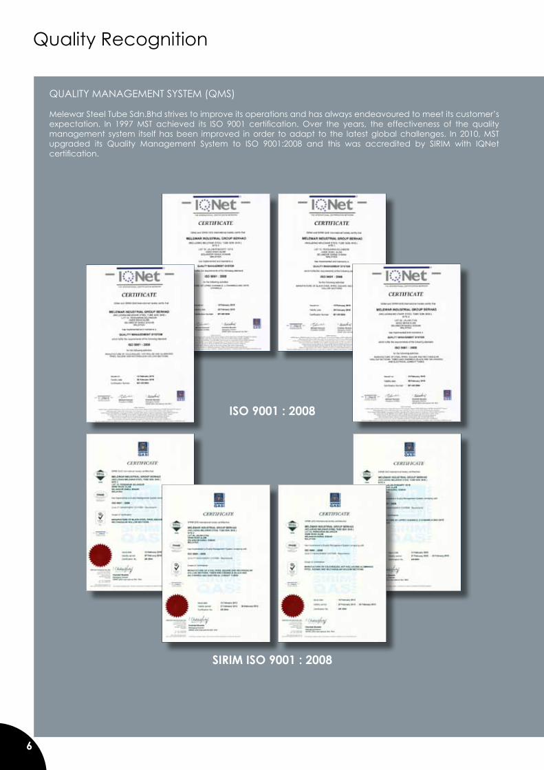
Quality Recognition
SIRIM ISO 9001 : 2008
QUALITY MANAGEMENT SYSTEM (QMS)
Melewar Steel Tube Sdn.Bhd strives to improve its operations and has always endeavoured to meet its customer’s expectation. In 1997 MST achieved its ISO 9001 certification. Over the years, the effectiveness of the quality management system itself has been improved in order to adapt to the latest global challenges. In 2010, MST upgraded its Quality Management System to ISO 9001:2008 and this was accredited by SIRIM with IQNet certification.
ISO 9001 : 2008
7
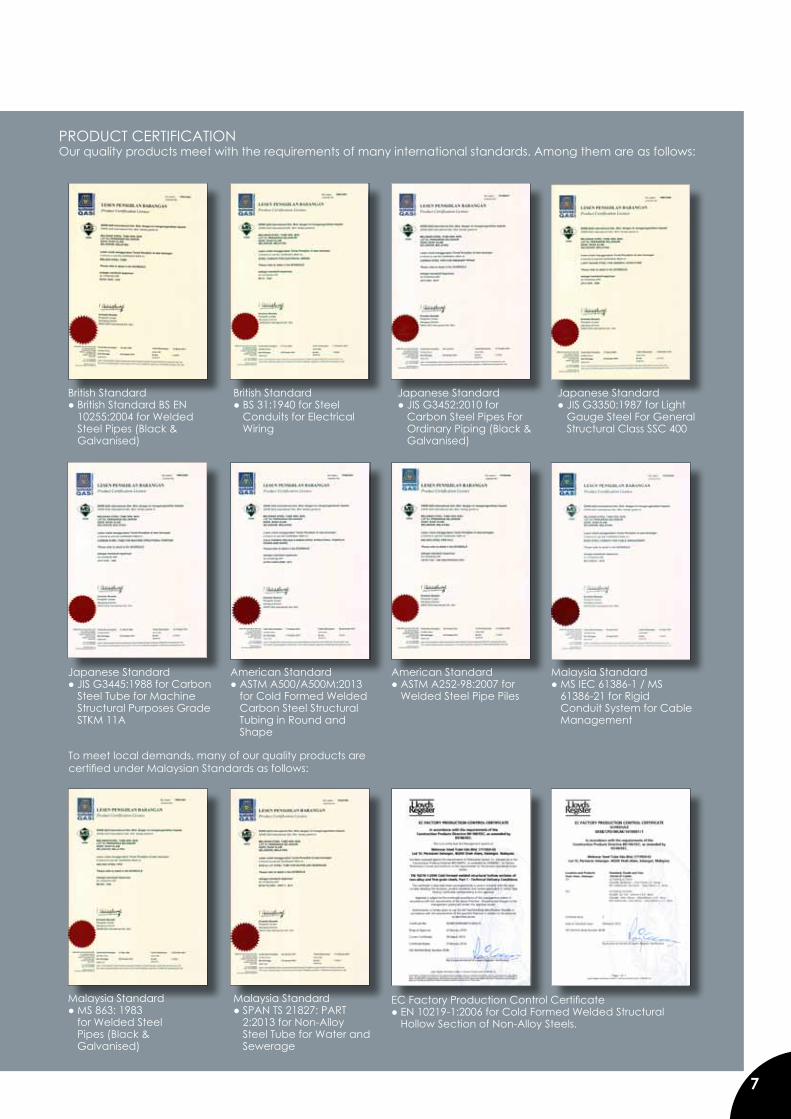
PRODUCT CERTIFICATION Our quality products meet with the requirements of many international standards. Among them are as follows:
To meet local demands, many of our quality products arecertified under Malaysian Standards as follows:
American Standard ● ASTM A252-98:2007 for
Welded Steel Pipe Piles
Japanese Standard● JIS G3445:1988 for Carbon
Steel Tube for Machine Structural Purposes Grade STKM 11A
American Standard ● ASTM A500/A500M:2013
for Cold Formed Welded Carbon Steel Structural Tubing in Round and Shape
British Standard● British Standard BS EN
10255:2004 for Welded Steel Pipes (Black & Galvanised)
EC Factory Production Control Certificate ● EN 10219-1:2006 for Cold Formed Welded Structural
Hollow Section of Non-Alloy Steels.
Malaysia Standard● MS 863: 1983 for Welded Steel Pipes (Black & Galvanised)
Malaysia Standard ● SPAN TS 21827: PART
2:2013 for Non-Alloy Steel Tube for Water and Sewerage
Malaysia Standard ● MS IEC 61386-1 / MS
61386-21 for Rigid Conduit System for Cable Management
British Standard● BS 31:1940 for Steel
Conduits for Electrical Wiring
Japanese Standard● JIS G3452:2010 for
Carbon Steel Pipes For Ordinary Piping (Black & Galvanised)
Japanese Standard● JIS G3350:1987 for Light
Gauge Steel For General Structural Class SSC 400
8
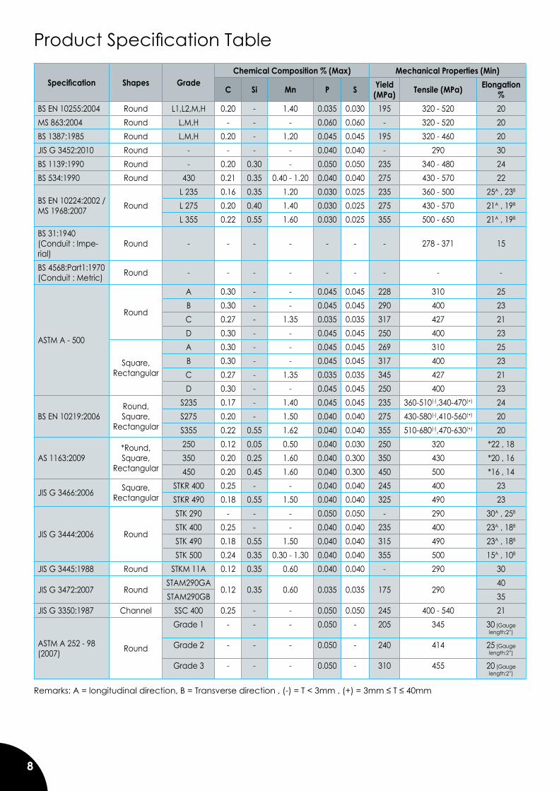
Product Specification Table
Specification Shapes GradeChemical Composition % (Max) Mechanical Properties (Min)
C Si Mn P S Yield (MPa) Tensile (MPa) Elongation
%BS EN 10255:2004 Round L1,L2,M,H 0.20 - 1.40 0.035 0.030 195 320 - 520 20MS 863:2004 Round L,M,H - - - 0.060 0.060 - 320 - 520 20BS 1387:1985 Round L,M,H 0.20 - 1.20 0.045 0.045 195 320 - 460 20JIS G 3452:2010 Round - - - - 0.040 0.040 - 290 30BS 1139:1990 Round - 0.20 0.30 - 0.050 0.050 235 340 - 480 24BS 534:1990 Round 430 0.21 0.35 0.40 - 1.20 0.040 0.040 275 430 - 570 22
BS EN 10224:2002 / MS 1968:2007 Round
L 235 0.16 0.35 1.20 0.030 0.025 235 360 - 500 25A , 23B
L 275 0.20 0.40 1.40 0.030 0.025 275 430 - 570 21A , 19B
L 355 0.22 0.55 1.60 0.030 0.025 355 500 - 650 21A , 19B
BS 31:1940 (Conduit : Impe-rial)
Round - - - - - - - 278 - 371 15
BS 4568:Part1:1970(Conduit : Metric) Round - - - - - - - - -
ASTM A - 500
Round
A 0.30 - - 0.045 0.045 228 310 25B 0.30 - - 0.045 0.045 290 400 23C 0.27 - 1.35 0.035 0.035 317 427 21D 0.30 - - 0.045 0.045 250 400 23
Square,Rectangular
A 0.30 - - 0.045 0.045 269 310 25B 0.30 - - 0.045 0.045 317 400 23C 0.27 - 1.35 0.035 0.035 345 427 21D 0.30 - - 0.045 0.045 250 400 23
BS EN 10219:2006Round,Square,
Rectangular
S235 0.17 - 1.40 0.045 0.045 235 360-510(-),340-470(+) 24S275 0.20 - 1.50 0.040 0.040 275 430-580(-),410-560(+) 20S355 0.22 0.55 1.62 0.040 0.040 355 510-680(-),470-630(+) 20
AS 1163:2009*Round,Square,
Rectangular
250 0.12 0.05 0.50 0.040 0.030 250 320 *22 , 18350 0.20 0.25 1.60 0.040 0.300 350 430 *20 , 16450 0.20 0.45 1.60 0.040 0.300 450 500 *16 , 14
JIS G 3466:2006 Square,Rectangular
STKR 400 0.25 - - 0.040 0.040 245 400 23STKR 490 0.18 0.55 1.50 0.040 0.040 325 490 23
JIS G 3444:2006 Round
STK 290 - - - 0.050 0.050 - 290 30A , 25B
STK 400 0.25 - - 0.040 0.040 235 400 23A , 18B
STK 490 0.18 0.55 1.50 0.040 0.040 315 490 23A , 18B
STK 500 0.24 0.35 0.30 - 1.30 0.040 0.040 355 500 15A , 10B
JIS G 3445:1988 Round STKM 11A 0.12 0.35 0.60 0.040 0.040 - 290 30
JIS G 3472:2007 RoundSTAM290GA
0.12 0.35 0.60 0.035 0.035 175 29040
STAM290GB 35JIS G 3350:1987 Channel SSC 400 0.25 - - 0.050 0.050 245 400 - 540 21
ASTM A 252 - 98 (2007) Round
Grade 1 - - - 0.050 - 205 345 30 (Gauge length:2”)
Grade 2 - - - 0.050 - 240 414 25 (Gauge length:2”)
Grade 3 - - - 0.050 - 310 455 20 (Gauge length:2”)
Remarks: A = longitudinal direction, B = Transverse direction , (-) = T < 3mm , (+) = 3mm ≤ T ≤ 40mm
9
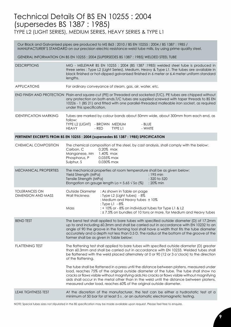
Technical Details Of BS EN 10255 : 2004(supersedes BS 1387 : 1985) TYPE L2 (LIGHT SERIES), MEDIUM SERIES, HEAVY SERIES & TYPE L1
Our Black and Galvanised pipes are produced to MS 863 : 2010 / BS EN 10255 : 2004 / BS 1387 : 1985 /MANUFACTURER’S STANDARD on our precision electric-resistance-weld tube mills, by using prime quality steel.
GENERAL INFORMATION ON BS EN 10255 : 2004 [SUPERSEDES BS 1387 : 1985] WELDED STEEL TUBE DESCRIPTIONS MIG - MELEWAR BS EN 10255 : 2004 (BS 1387 :1985) welded steel tube is produced in
three series : Type L2 (Light Series), Medium, Heavy & Type L1. The tubes are available in black finished or hot-dipped galvanised finished in 6 meter or 6.4 meter uniform standard lengths.
APPLICATIONS For ordinary conveyance of steam, gas, air, water, etc.
END FINISH AND PROTECTION Plain-end square-cut (PE) or Threaded and socketed (T/C). PE tubes are chipped without any protection on both ends.T/C tubes are supplied screwed with taper threads to BS EN 10226 - 1 (BS 21) and fitted with one parallel-threaded malleable iron socket, as required under this specification.
IDENTIFICATION MARKING Tubes are marked by colour bands about 50mm wide, about 300mm from each end, as follow:
TYPE L2 (LIGHT) - BROWN MEDIUM - BLUE HEAVY - RED TYPE L1 - WHITE PERTINENT EXCERPTS FROM BS EN 10255 : 2004 (supersedes BS 1387 : 1985) SPECIFICATION
CHEMICAL COMPOSITION The chemical composition of the steel, by cast analysis, shall comply with the below:
Carbon, C 0.20% max Manganese, Mn 1.40% max Phosphorus, P 0.035% max Sulphur, S 0.030% max
MECHANICAL PROPERTIES The mechanical properties at room temperature shall be as given below: Yield Strength (MPa) : 195 min
Tensile Strength (MPa) : 320 to 520 Elongation on gauge length Lo = 5.65 √ So (%) : 20% min
TOLERANCES ON Outside Diameter : As shown in Table on page DIMENSION AND MASS Wall thickness : Type L2 (Light tubes) - 8% : Medium and Heavy tubes ± 10% : Type L1 - 8% Mass : + 10% or - 8% on individual tubes for Type L1 & L2 : ± 7.5% on bundles of 10 tons or more, for Medium and Heavy tubes
BEND TEST The bend test shall applied to bare tubes with specified outside diameter (D) of 17.2mm
up to and including 60.3mm and shall be carried out in accordance with EN 10232 to an angle of 90 the groove in the forming tool shall have a width that fits the tube diameter accurately and a depth not less than 0.5 D. The radius at the bottom of the groove of the former shall be as given in Table below:
FLATTENING TEST The flattening test shall applied to bare tubes with specified outside diameter (D) greater than 60.3mm and shall be carried out in accordance with EN 10233. Welded tubes shall be flattened with the weld placed alternately at 0 or 90 (12 or 3 o’clock) to the direction of the flattening.
The tube shall be flattened in a press until the distance between platens, measured under
load, reaches 75% of the original outside diameter of the tube. The tube shall show no cracks or flaws visible without magnifying aids.No cracks or flaws visible without magnifying aids shall occur in the metal other than in the weld until the distance between platens, measured under load, reaches 60% of the original outside diameter.
LEAK TIGHTNESS TEST At the discretion of the manufacturer, the test can be either a hydrostatic test at a minimum of 50 bar for at least 5 s , or an automatic electromagnetic testing.
NOTE: Special tubes sizes not stipulated in the BS specification may be made available upon request. Please feel free to enquire.
10
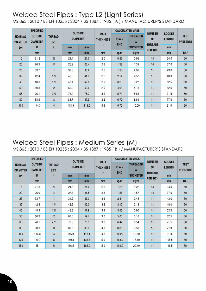
Welded Steel Pipes : Type L2 (Light Series)MS 863 : 2010 / BS EN 10255 : 2004 / BS 1387 : 1985 ( A ) / MANUFACTURER’S STANDARD
Welded Steel Pipes : Medium Series (M) MS 863 : 2010 / BS EN 10255 : 2004 / BS 1387 : 1985 ( B ) / MANUFACTURER’S STANDARD
15 21.3 ½ 21.4 21.0 2.0 0.95 0.96 14 34.0 50
20 26.9 ¾ 26.9 26.4 2.3 1.38 1.39 14 37.0 50
25 33.7 1 33.8 33.2 2.6 1.98 2.00 11 43.0 50
32 42.4 1 ¼ 42.5 41.9 2.6 2.54 2.57 11 48.0 50
40 48.3 1 ½ 48.4 47.8 2.9 3.23 3.27 11 52.5 50
50 60.3 2 60.2 59.6 2.9 4.08 4.15 11 62.5 50
65 76.1 2 ½ 76.0 75.2 3.2 5.71 5.83 11 71.5 50
80 88.9 3 88.7 87.9 3.2 6.72 6.89 11 77.0 50
100 114.3 4 113.9 113.0 3.6 9.75 10.00 11 91.0 50
SPECIFIED CALCULATED MASS
OUTSIDE THREADED TEST
DIAMETER & PRESSURE
D max min SOCKETED min
mm mm mm mm kg/m kg/m mm BAR
OUTSIDE
DIAMETER
15 21.3 ½ 21.8 21.0 2.6 1.21 1.22 14 34.0 50
20 26.9 ¾ 27.3 26.5 2.6 1.56 1.57 14 37.0 50
25 33.7 1 34.2 33.3 3.2 2.41 2.43 11 43.0 50
32 42.4 1 ¼ 42.9 42.0 3.2 3.10 3.13 11 48.0 50
40 48.3 1 ½ 48.8 47.9 3.2 3.56 3.60 11 52.5 50
50 60.3 2 60.8 59.7 3.6 5.03 5.10 11 62.5 50
65 76.1 2 ½ 76.6 75.3 3.6 6.42 6.54 11 71.5 50
80 88.9 3 89.5 88.0 4.0 8.36 8.53 11 77.0 50
100 114.3 4 115.0 113.1 4.5 12.20 12.50 11 91.0 50
125 139.7 5 140.8 138.5 5.0 16.60 17.10 11 105.5 50
150 165.1 6 166.5 163.9 5.0 19.80 20.40 11 116.5 50
NOMINAL
DIAMETER
DN
THREAD
SIZE
R
WALL
THICKNESS
T
PLAIN
END
SOCKET
LENGTH
NUMBER
OF
THREADS
PER INCH
SPECIFIED CALCULATED MASS
OUTSIDE THREADED TEST
DIAMETER & PRESSURE
D max min SOCKETED min
mm mm mm mm kg/m kg/m mm BAR
OUTSIDE
DIAMETERNOMINAL
DIAMETER
DN
THREAD
SIZE
R
WALL
THICKNESS
T
PLAIN
END
SOCKET
LENGTH
NUMBER
OF
THREADS
PER INCH
11
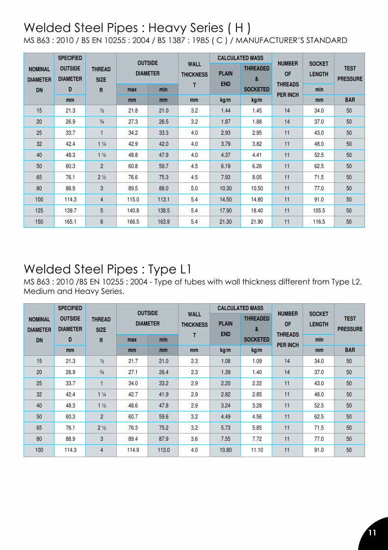
Welded Steel Pipes : Heavy Series ( H )MS 863 : 2010 / BS EN 10255 : 2004 / BS 1387 : 1985 ( C ) / MANUFACTURER’S STANDARD
MS 863 : 2010 /BS EN 10255 : 2004 - Type of tubes with wall thickness different from Type L2, Medium and Heavy Series.
Welded Steel Pipes : Type L1
15 21.3 ½ 21.7 21.0 2.3 1.08 1.09 14 34.0 50
20 26.9 ¾ 27.1 26.4 2.3 1.39 1.40 14 37.0 50
25 33.7 1 34.0 33.2 2.9 2.20 2.22 11 43.0 50
32 42.4 1 ¼ 42.7 41.9 2.9 2.82 2.85 11 48.0 50
40 48.3 1 ½ 48.6 47.8 2.9 3.24 3.28 11 52.5 50
50 60.3 2 60.7 59.6 3.2 4.49 4.56 11 62.5 50
65 76.1 2 ½ 76.3 75.2 3.2 5.73 5.85 11 71.5 50
80 88.9 3 89.4 87.9 3.6 7.55 7.72 11 77.0 50
100 114.3 4 114.9 113.0 4.0 10.80 11.10 11 91.0 50
15 21.3 ½ 21.8 21.0 3.2 1.44 1.45 14 34.0 50
20 26.9 ¾ 27.3 26.5 3.2 1.87 1.88 14 37.0 50
25 33.7 1 34.2 33.3 4.0 2.93 2.95 11 43.0 50
32 42.4 1 ¼ 42.9 42.0 4.0 3.79 3.82 11 48.0 50
40 48.3 1 ½ 48.8 47.9 4.0 4.37 4.41 11 52.5 50
50 60.3 2 60.8 59.7 4.5 6.19 6.26 11 62.5 50
65 76.1 2 ½ 76.6 75.3 4.5 7.93 8.05 11 71.5 50
80 88.9 3 89.5 88.0 5.0 10.30 10.50 11 77.0 50
100 114.3 4 115.0 113.1 5.4 14.50 14.80 11 91.0 50
125 139.7 5 140.8 138.5 5.4 17.90 18.40 11 105.5 50
150 165.1 6 166.5 163.9 5.4 21.30 21.90 11 116.5 50
SPECIFIED CALCULATED MASS
OUTSIDE THREADED TEST
DIAMETER & PRESSURE
D max min SOCKETED min
mm mm mm mm kg/m kg/m mm BAR
OUTSIDE
DIAMETERNOMINAL
DIAMETER
DN
THREAD
SIZE
R
WALL
THICKNESS
T
PLAIN
END
SOCKET
LENGTH
NUMBER
OF
THREADS
PER INCH
SPECIFIED CALCULATED MASS
OUTSIDE THREADED TEST
DIAMETER & PRESSURE
D max min SOCKETED min
mm mm mm mm kg/m kg/m mm BAR
OUTSIDE
DIAMETERNOMINAL
DIAMETER
DN
THREAD
SIZE
R
WALL
THICKNESS
T
PLAIN
END
SOCKET
LENGTH
NUMBER
OF
THREADS
PER INCH
12
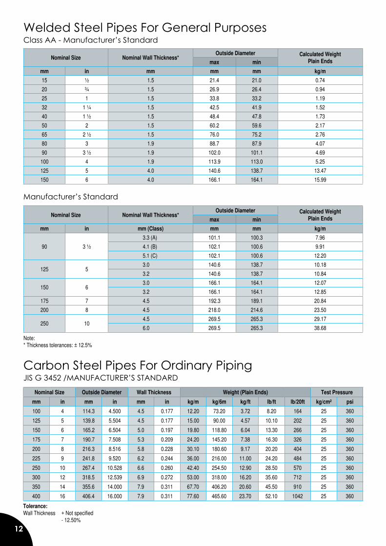
Welded Steel Pipes For General PurposesClass AA - Manufacturer’s Standard
Manufacturer’s Standard
Carbon Steel Pipes For Ordinary PipingJIS G 3452 /MANUFACTURER’S STANDARD
Nominal Size Nominal Wall Thickness*Outside Diameter Calculated Weight
Plain Endsmax min
mm in mm (Class) mm mm kg/m
90 3 ½
3.3 (A) 101.1 100.3 7.96
4.1 (B) 102.1 100.6 9.91
5.1 (C) 102.1 100.6 12.20
125 5 3.0 140.6 138.7 10.18
3.2 140.6 138.7 10.84
150 6 3.0 166.1 164.1 12.07
3.2 166.1 164.1 12.85
175 7 4.5 192.3 189.1 20.84
200 8 4.5 218.0 214.6 23.50
250 10 4.5 269.5 265.3 29.17
6.0 269.5 265.3 38.68
Nominal Size Nominal Wall Thickness*Outside Diameter Calculated Weight
Plain Endsmax min
mm in mm mm mm kg/m
15 ½ 1.5 21.4 21.0 0.74
20 ¾ 1.5 26.9 26.4 0.94
25 1 1.5 33.8 33.2 1.19
32 1 ¼ 1.5 42.5 41.9 1.52
40 1 ½ 1.5 48.4 47.8 1.73
50 2 1.5 60.2 59.6 2.17
65 2 ½ 1.5 76.0 75.2 2.76
80 3 1.9 88.7 87.9 4.07
90 3 ½ 1.9 102.0 101.1 4.69
100 4 1.9 113.9 113.0 5.25
125 5 4.0 140.6 138.7 13.47
150 6 4.0 166.1 164.1 15.99
Note:* Thickness tolerances: ± 12.5%
Nominal Size Outside Diameter Wall Thickness Weight (Plain Ends) Test Pressure
mm in mm in mm in kg/m kg/6m kg/ft lb/ft lb/20ft kg/cm² psi
100 4 114.3 4.500 4.5 0.177 12.20 73.20 3.72 8.20 164 25 360
125 5 139.8 5.504 4.5 0.177 15.00 90.00 4.57 10.10 202 25 360
150 6 165.2 6.504 5.0 0.197 19.80 118.80 6.04 13.30 266 25 360
175 7 190.7 7.508 5.3 0.209 24.20 145.20 7.38 16.30 326 25 360
200 8 216.3 8.516 5.8 0.228 30.10 180.60 9.17 20.20 404 25 360
225 9 241.8 9.520 6.2 0.244 36.00 216.00 11.00 24.20 484 25 360
250 10 267.4 10.528 6.6 0.260 42.40 254.50 12.90 28.50 570 25 360
300 12 318.5 12.539 6.9 0.272 53.00 318.00 16.20 35.60 712 25 360
350 14 355.6 14.000 7.9 0.311 67.70 406.20 20.60 45.50 910 25 360
400 16 406.4 16.000 7.9 0.311 77.60 465.60 23.70 52.10 1042 25 360
Tolerance: Wall Thickness + Not specified - 12.50%
13
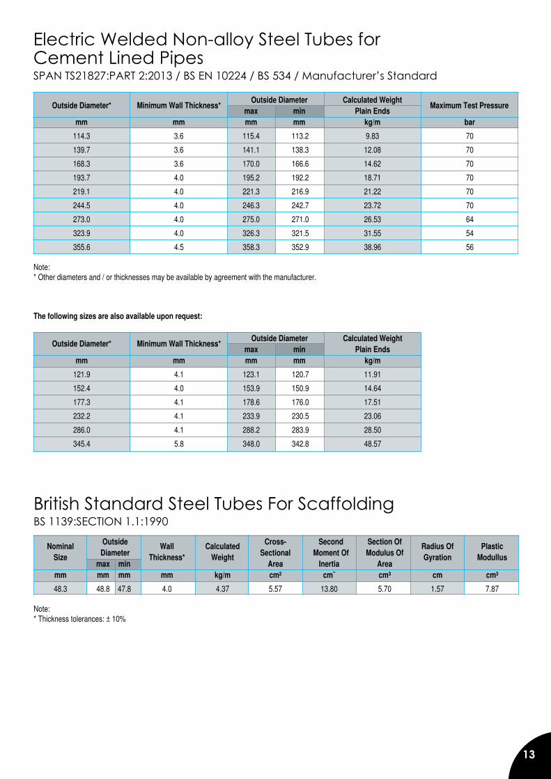
Electric Welded Non-alloy Steel Tubes forCement Lined PipesSPAN TS21827:PART 2:2013 / BS EN 10224 / BS 534 / Manufacturer’s Standard
Outside Diameter Calculated Weight max min Plain Ends mm mm mm mm kg/m bar
114.3 3.6 115.4 113.2 9.83 70
139.7 3.6 141.1 138.3 12.08 70
168.3 3.6 170.0 166.6 14.62 70
193.7 4.0 195.2 192.2 18.71 70
219.1 4.0 221.3 216.9 21.22 70
244.5 4.0 246.3 242.7 23.72 70
273.0 4.0 275.0 271.0 26.53 64
323.9 4.0 326.3 321.5 31.55 54
355.6 4.5 358.3 352.9 38.96 56 Note: * Other diameters and / or thicknesses may be available by agreement with the manufacturer.
The following sizes are also available upon request: Outside Diameter Calculated Weight max min Plain Ends mm mm mm mm kg/m
121.9 4.1 123.1 120.7 11.91
152.4 4.0 153.9 150.9 14.64
177.3 4.1 178.6 176.0 17.51
232.2 4.1 233.9 230.5 23.06
286.0 4.1 288.2 283.9 28.50
345.4 5.8 348.0 342.8 48.57
Outside Diameter* Minimum Wall Thickness* Maximum Test Pressure
Outside Diameter* Minimum Wall Thickness*
British Standard Steel Tubes For ScaffoldingBS 1139:SECTION 1.1:1990
Outside Cross- Second Section Of Diameter Sectional Moment Of Modulus Of max min Area Inertia Area mm mm mm mm kg/m cm² cm� cm³ cm cm³
48.3 48.8 47.8 4.0 4.37 5.57 13.80 5.70 1.57 7.87
Note:* Thickness tolerances: ± 10%
Nominal Wall Calculated Radius Of Plastic Size Thickness* Weight Gyration Modullus
14
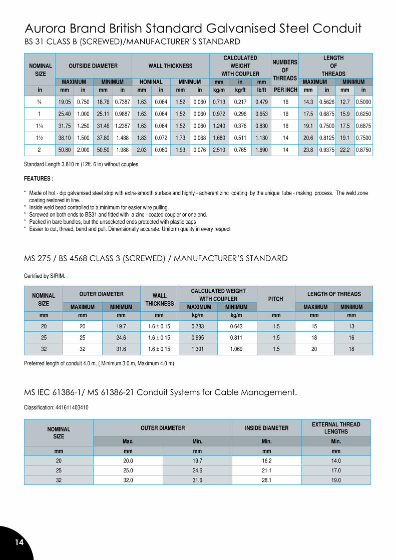
Aurora Brand British Standard Galvanised Steel ConduitBS 31 CLASS B (SCREWED)/MANUFACTURER’S STANDARD
CALCULATED LENGTH NOMINAL OUTSIDE DIAMETER WALL THICKNESS WEIGHT OF SIZE WITH COUPLER THREADS MAXIMUM MINIMUM NOMINAL MINIMUM mm in mm MAXIMUM MINIMUM in mm in mm in mm in mm in kg/m kg/ft lb/ft PER INCH mm in mm in
¾ 19.05 0.750 18.76 0.7387 1.63 0.064 1.52 0.060 0.713 0.217 0.479 16 14.3 0.5626 12.7 0.5000
1 25.40 1.000 25.11 0.9887 1.63 0.064 1.52 0.060 0.972 0.296 0.653 16 17.5 0.6875 15.9 0.6250
1¼ 31.75 1.250 31.46 1.2387 1.63 0.064 1.52 0.060 1.240 0.376 0.830 16 19.1 0.7500 17.5 0.6875
1½ 38.10 1.500 37.80 1.488 1.83 0.072 1.73 0.068 1.680 0.511 1.130 14 20.6 0.8125 19.1 0.7500
2 50.80 2.000 50.50 1.988 2.03 0.080 1.93 0.076 2.510 0.765 1.690 14 23.8 0.9375 22.2 0.8750
Standard Length 3.810 m (12ft. 6 in) without couples FEATURES : * Made of hot - dip galvanised steel strip with extra-smooth surface and highly - adherent zinc coating by the unique tube - making process. The weld zone
coating restored in line.* Inside weld bead controlled to a minimum for easier wire pulling.* Screwed on both ends to BS31 and fitted with a zinc - coated coupler or one end.* Packed in bare bundles, but the unsocketed ends protected with plastic caps* Easier to cut, thread, bend and pull. Dimensionally accurate. Uniform quality in every respect
MS 275 / BS 4568 CLASS 3 (SCREWED) / MANUFACTURER’S STANDARD Certified by SIRIM. CALCULATED WEIGHT WITH COUPLER PITCH MAXIMUM MINIMUM MAXIMUM MINIMUM MAXIMUM MINIMUM mm mm mm mm kg/m kg/m mm mm mm
20 20 19.7 1.6 ± 0.15 0.783 0.643 1.5 15 13
25 25 24.6 1.6 ± 0.15 0.995 0.811 1.5 18 16
32 32 31.6 1.6 ± 0.15 1.301 1.069 1.5 20 18 Preferred length of conduit 4.0 m. ( Minimum 3.0 m, Maximum 4.0 m)
OUTER DIAMETER LENGTH OF THREADSNOMINALSIZE
WALLTHICKNESS
NUMBERSOF
THREADS
MS IEC 61386-1/ MS 61386-21 Conduit Systems for Cable Management.
Classification: 441611403410
NOMINALSIZE
OUTER DIAMETER INSIDE DIAMETEREXTERNAL THREAD
LENGTHS
Max. Min. Min. Min.
mm mm mm mm mm
20 20.0 19.7 16.2 14.0
25 25.0 24.6 21.1 17.0
32 32.0 31.6 28.1 19.0
15
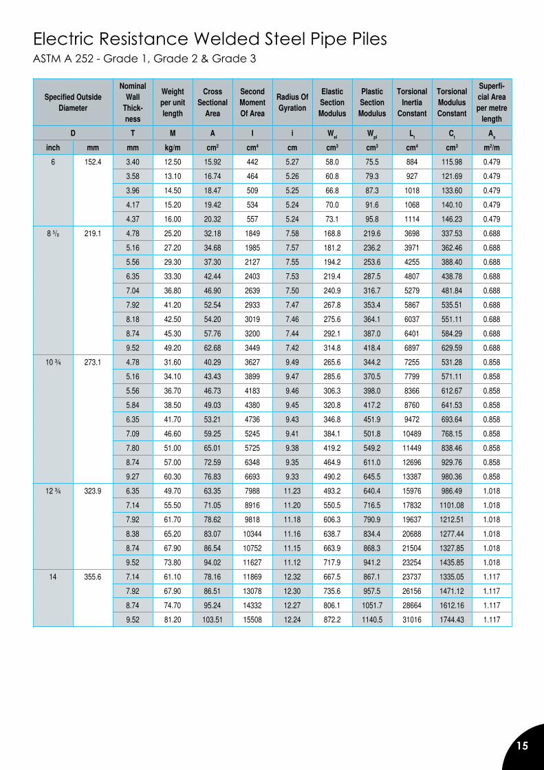
Electric Resistance Welded Steel Pipe PilesASTM A 252 - Grade 1, Grade 2 & Grade 3
Specified Outside Diameter
Nominal Wall
Thick-ness
Weight per unit length
Cross Sectional
Area
Second Moment Of Area
Radius Of Gyration
Elastic Section Modulus
Plastic Section Modulus
Torsional Inertia
Constant
Torsional Modulus Constant
Superfi-cial Area per metre
length
D T M A I i Wel Wpl Lt Ct As
inch mm mm kg/m cm2 cm4 cm cm3 cm3 cm4 cm3 m2/m
6 152.4 3.40 12.50 15.92 442 5.27 58.0 75.5 884 115.98 0.479
3.58 13.10 16.74 464 5.26 60.8 79.3 927 121.69 0.479
3.96 14.50 18.47 509 5.25 66.8 87.3 1018 133.60 0.479
4.17 15.20 19.42 534 5.24 70.0 91.6 1068 140.10 0.479
4.37 16.00 20.32 557 5.24 73.1 95.8 1114 146.23 0.479
8 5/8 219.1 4.78 25.20 32.18 1849 7.58 168.8 219.6 3698 337.53 0.688
5.16 27.20 34.68 1985 7.57 181.2 236.2 3971 362.46 0.688
5.56 29.30 37.30 2127 7.55 194.2 253.6 4255 388.40 0.688
6.35 33.30 42.44 2403 7.53 219.4 287.5 4807 438.78 0.688
7.04 36.80 46.90 2639 7.50 240.9 316.7 5279 481.84 0.688
7.92 41.20 52.54 2933 7.47 267.8 353.4 5867 535.51 0.688
8.18 42.50 54.20 3019 7.46 275.6 364.1 6037 551.11 0.688
8.74 45.30 57.76 3200 7.44 292.1 387.0 6401 584.29 0.688
9.52 49.20 62.68 3449 7.42 314.8 418.4 6897 629.59 0.688
10 ¾ 273.1 4.78 31.60 40.29 3627 9.49 265.6 344.2 7255 531.28 0.858
5.16 34.10 43.43 3899 9.47 285.6 370.5 7799 571.11 0.858
5.56 36.70 46.73 4183 9.46 306.3 398.0 8366 612.67 0.858
5.84 38.50 49.03 4380 9.45 320.8 417.2 8760 641.53 0.858
6.35 41.70 53.21 4736 9.43 346.8 451.9 9472 693.64 0.858
7.09 46.60 59.25 5245 9.41 384.1 501.8 10489 768.15 0.858
7.80 51.00 65.01 5725 9.38 419.2 549.2 11449 838.46 0.858
8.74 57.00 72.59 6348 9.35 464.9 611.0 12696 929.76 0.858
9.27 60.30 76.83 6693 9.33 490.2 645.5 13387 980.36 0.858
12 ¾ 323.9 6.35 49.70 63.35 7988 11.23 493.2 640.4 15976 986.49 1.018
7.14 55.50 71.05 8916 11.20 550.5 716.5 17832 1101.08 1.018
7.92 61.70 78.62 9818 11.18 606.3 790.9 19637 1212.51 1.018
8.38 65.20 83.07 10344 11.16 638.7 834.4 20688 1277.44 1.018
8.74 67.90 86.54 10752 11.15 663.9 868.3 21504 1327.85 1.018
9.52 73.80 94.02 11627 11.12 717.9 941.2 23254 1435.85 1.018
14 355.6 7.14 61.10 78.16 11869 12.32 667.5 867.1 23737 1335.05 1.117
7.92 67.90 86.51 13078 12.30 735.6 957.5 26156 1471.12 1.117
8.74 74.70 95.24 14332 12.27 806.1 1051.7 28664 1612.16 1.117
9.52 81.20 103.51 15508 12.24 872.2 1140.5 31016 1744.43 1.117
16
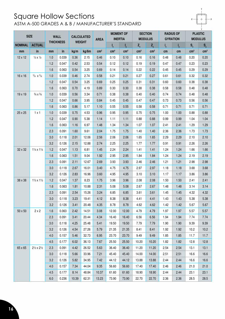
Square Hollow SectionsASTM A-500 GRADES A & B / MANUFACTURER’S STANDARD
SIZE WALL
THICKNESS
CALCULATED
WEIGHTAREA
MOMENT OF
INERTIA
SECTION
MODULUS
RADIUS OF
GYRATION
PLASTIC
MODULUS
NOMINAL ACTUAL Ix Iy Zx Zy ix iy Sx Sy
mm in mm in kg/m kg/6m cm2 cm4 cm4 cm3 cm3 cm cm cm3 cm3
12 x 12 ½ x ½ 1.0 0.039 0.36 2.15 0.46 0.10 0.10 0.16 0.16 0.48 0.48 0.20 0.20
1.2 0.047 0.42 2.53 0.54 0.12 0.12 0.19 0.19 0.47 0.47 0.23 0.23
1.6 0.063 0.54 3.25 0.69 0.14 0.14 0.22 0.22 0.45 0.45 0.29 0.29
16 x 16 5/8 x 5/8 1.0 0.039 0.46 2.74 0.58 0.21 0.21 0.27 0.27 0.61 0.61 0.32 0.32
1.2 0.047 0.54 3.25 0.69 0.25 0.25 0.31 0.31 0.60 0.60 0.38 0.38
1.6 0.063 0.70 4.19 0.89 0.30 0.30 0.38 0.38 0.58 0.58 0.48 0.48
19 x 19 ¾ x ¾ 1.0 0.039 0.56 3.34 0.71 0.38 0.38 0.40 0.40 0.74 0.74 0.48 0.48
1.2 0.047 0.66 3.95 0.84 0.45 0.45 0.47 0.47 0.73 0.73 0.56 0.56
1.6 0.063 0.86 5.17 1.10 0.55 0.55 0.58 0.58 0.71 0.71 0.71 0.71
25 x 25 1 x 1 1.0 0.039 0.75 4.53 0.96 0.95 0.95 0.75 0.75 1.00 1.00 0.88 0.88
1.2 0.047 0.90 5.38 1.14 1.11 1.11 0.88 0.88 0.99 0.99 1.04 1.04
1.6 0.063 1.16 6.97 1.48 1.34 1.34 1.07 1.07 2.41 2.41 1.29 1.29
2.3 0.091 1.60 9.61 2.04 1.75 1.75 1.40 1.40 2.36 2.36 1.73 1.73
3.0 0.118 2.01 12.06 2.56 2.06 2.06 1.65 1.65 2.29 2.29 2.10 2.10
3.2 0.126 2.15 12.88 2.74 2.25 2.25 1.77 1.77 0.91 0.91 2.26 2.26
32 x 32 1¼ x 1¼ 1.2 0.047 1.13 6.81 1.45 2.24 2.24 1.41 1.41 1.24 1.24 1.66 1.66
1.6 0.063 1.51 9.04 1.92 2.95 2.95 1.84 1.84 1.24 1.24 2.19 2.19
2.3 0.091 2.11 12.67 2.69 3.93 3.93 2.46 2.46 1.21 1.21 2.98 2.98
3.0 0.118 2.67 16.01 3.40 4.75 4.75 2.97 2.97 1.18 1.18 3.68 3.68
3.2 0.126 2.83 16.96 3.60 4.95 4.95 3.10 3.10 1.17 1.17 3.86 3.86
38 x 38 1½ x 1½ 1.2 0.047 1.37 8.23 1.75 3.96 3.96 2.08 2.08 1.50 1.50 2.41 2.41
1.6 0.063 1.81 10.88 2.31 5.08 5.08 2.67 2.67 1.48 1.48 3.14 3.14
2.3 0.091 2.54 15.26 3.24 6.85 6.85 3.61 3.61 1.45 1.45 4.32 4.32
3.0 0.118 3.23 19.41 4.12 8.38 8.38 4.41 4.41 1.43 1.43 5.38 5.38
3.2 0.126 3.41 20.48 4.35 8.78 8.78 4.62 4.62 1.42 1.42 5.67 5.67
50 x 50 2 x 2 1.6 0.063 2.42 14.51 3.08 12.00 12.00 4.79 4.79 1.97 1.97 5.57 5.57
2.3 0.091 3.41 20.44 4.34 16.40 16.40 6.56 6.56 1.94 1.94 7.74 7.74
3.0 0.118 4.25 25.48 5.41 19.50 19.50 7.79 7.79 1.90 1.90 9.39 9.39
3.2 0.126 4.54 27.26 5.79 21.35 21.35 8.41 8.41 1.92 1.92 10.2 10.2
4.0 0.157 5.46 32.73 6.95 23.70 23.70 9.49 9.49 1.85 1.85 11.7 11.7
4.5 0.177 6.02 36.13 7.67 25.50 25.50 10.20 10.20 1.82 1.82 12.8 12.8
65 x 65 2½ x 2½ 2.3 0.091 4.42 26.52 5.63 36.40 36.40 11.20 11.20 2.54 2.54 13.1 13.1
3.0 0.118 5.66 33.96 7.21 45.40 45.40 14.00 14.00 2.51 2.51 16.6 16.6
3.2 0.126 5.82 34.95 7.42 44.12 44.12 13.88 13.88 2.44 2.44 16.6 16.6
4.0 0.157 7.34 44.04 9.35 56.60 56.60 17.40 17.40 2.46 2.46 21.0 21.0
4.5 0.177 8.14 48.84 10.37 61.60 61.60 18.90 18.90 2.44 2.44 23.1 23.1
6.0 0.236 10.39 62.31 13.23 73.90 73.90 22.70 22.70 2.36 2.36 28.5 28.5
17
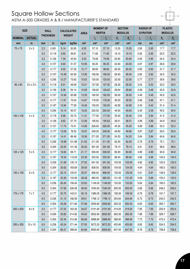
ASTM A-500 GRADES A & B / MANUFACTURER’S STANDARDSquare Hollow Sections
SIZE WALL
THICKNESS
CALCULATED
WEIGHTAREA
MOMENT OF
INERTIA
SECTION
MODULUS
RADIUS OF
GYRATION
PLASTIC
MODULUS
NOMINAL ACTUAL Ix Iy Zx Zy ix iy Sx Sy
mm in mm in kg/m kg/6m cm2 cm4 cm4 cm3 cm3 cm cm cm3 cm3
75 x 75 3 x 3 2.3 0.091 5.14 30.85 6.55 57.10 57.10 15.20 15.20 2.95 2.95 17.7 17.7
3.0 0.118 6.60 39.61 8.41 71.60 71.60 19.10 19.10 2.92 2.92 22.5 22.5
3.2 0.126 7.09 42.54 9.03 79.08 79.08 20.65 20.65 2.95 2.95 24.4 24.4
4.0 0.157 8.60 51.57 10.95 90.20 90.20 24.00 24.00 2.87 2.87 28.8 28.8
4.5 0.177 9.55 57.32 12.17 98.60 98.60 26.30 26.30 2.85 2.85 31.7 31.7
5.0 0.197 10.49 62.93 13.36 106.00 106.00 28.40 28.40 2.82 2.82 34.5 34.5
6.0 0.236 12.27 73.62 15.63 120.00 120.00 32.00 32.00 2.77 2.77 39.6 39.6
90 x 90 3½ x 3½ 3.0 0.118 8.01 48.09 10.21 127.00 127.00 28.30 28.30 3.53 3.53 33.0 33.0
3.2 0.126 8.36 50.14 10.65 128.62 128.62 28.84 28.84 3.48 3.48 33.9 33.9
4.0 0.157 10.48 62.88 13.35 162.00 162.00 36.00 36.00 3.48 3.48 42.6 42.6
4.5 0.177 11.67 70.04 14.87 178.00 178.00 39.50 39.50 3.46 3.46 47.1 47.1
5.0 0.197 12.84 77.06 16.36 193.00 193.00 42.90 42.90 3.43 3.43 51.4 51.4
6.0 0.236 15.10 90.57 19.23 220.00 220.00 49.00 49.00 3.39 3.39 59.5 59.5
100 x 100 4 x 4 3.0 0.118 8.96 53.74 11.41 177.00 177.00 35.40 35.40 3.94 3.94 41.2 41.2
3.2 0.126 9.62 57.74 12.26 195.63 195.63 38.51 38.51 3.99 3.99 44.9 44.9
4.0 0.157 11.74 70.41 14.95 226.00 226.00 45.30 45.30 3.89 3.89 53.3 53.3
4.5 0.177 13.09 78.52 16.67 249.00 249.00 49.90 49.90 3.87 3.87 59.0 59.0
5.0 0.197 14.41 86.48 18.36 271.00 271.00 54.20 54.20 3.84 3.84 64.6 64.6
6.0 0.236 16.98 101.88 21.63 311.00 311.00 62.30 62.30 3.79 3.79 75.1 75.1
9.0 0.354 23.55 141.30 30.00 391.00 391.00 78.10 78.10 3.61 3.61 98.6 98.6
125 x 125 5 x 5 4.5 0.177 16.62 99.71 21.17 506.00 506.00 80.90 80.90 4.89 4.89 94.8 94.8
5.0 0.197 18.34 110.03 23.36 553.00 553.00 88.40 88.40 4.86 4.86 104.0 104.0
6.0 0.236 21.69 130.14 27.63 641.00 641.00 103.00 103.00 4.82 4.82 122.0 122.0
9.0 0.354 30.62 183.69 39.00 838.00 838.00 134.00 134.00 4.64 4.64 165.0 165.0
150 x 150 6 x 6 4.5 0.177 20.15 120.91 25.67 896.00 896.00 120.00 120.00 5.91 5.91 139.0 139.0
5.0 0.197 22.26 133.58 28.36 982.00 982.00 131.00 131.00 5.89 5.89 153.0 153.0
6.0 0.236 26.40 158.40 33.63 1146.00 1146.00 153.00 153.00 5.84 5.84 180.0 180.0
9.0 0.354 37.68 226.08 48.00 1540.00 1540.00 205.00 205.00 5.66 5.66 248.0 248.0
175 x 175 7 x 7 4.5 0.177 23.70 142.21 30.19 1386.05 1386.05 158.30 158.30 6.78 6.78 191.7 191.7
6.0 0.236 31.10 186.58 39.61 1798.12 1798.12 204.84 204.84 6.73 6.73 242.5 242.5
9.0 0.354 45.28 271.66 57.68 2559.82 2559.82 293.33 293.33 6.65 6.65 350.7 350.7
200 x 200 8 x 8 4.5 0.177 27.22 163.30 34.67 2191.60 2191.60 219.20 219.20 7.95 7.95 252.9 252.9
6.0 0.236 35.82 214.92 45.63 2832.90 2832.90 283.30 283.30 7.88 7.88 329.7 329.7
9.0 0.354 52.34 314.06 66.68 3988.80 3988.80 398.90 398.90 7.73 7.73 472.4 472.4
250 x 250 10 x 10 6.0 0.236 45.24 271.44 57.63 5672.20 5672.20 453.80 453.80 9.92 9.92 524.5 524.5
9.0 0.354 66.47 398.84 84.68 8093.60 8093.60 647.50 647.50 9.78 9.78 758.8 758.8
18
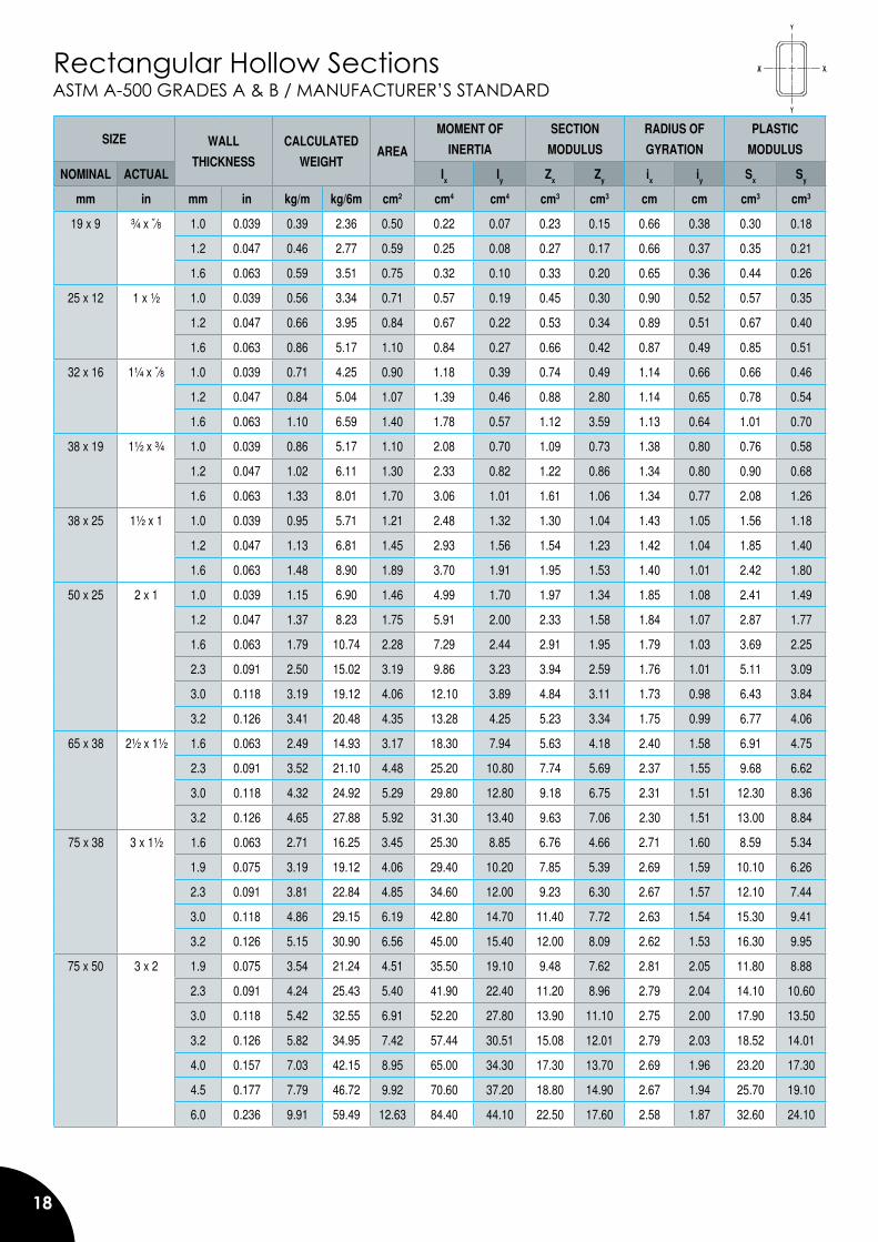
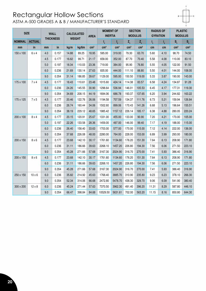
Rectangular Hollow SectionsASTM A-500 GRADES A & B / MANUFACTURER’S STANDARD
SIZE WALL
THICKNESS
CALCULATED
WEIGHTAREA
MOMENT OF
INERTIA
SECTION
MODULUS
RADIUS OF
GYRATION
PLASTIC
MODULUS
NOMINAL ACTUAL Ix Iy Zx Zy ix iy Sx Sy
mm in mm in kg/m kg/6m cm2 cm4 cm4 cm3 cm3 cm cm cm3 cm3
19 x 9 ¾ x �∕8 1.0 0.039 0.39 2.36 0.50 0.22 0.07 0.23 0.15 0.66 0.38 0.30 0.18
1.2 0.047 0.46 2.77 0.59 0.25 0.08 0.27 0.17 0.66 0.37 0.35 0.21
1.6 0.063 0.59 3.51 0.75 0.32 0.10 0.33 0.20 0.65 0.36 0.44 0.26
25 x 12 1 x ½ 1.0 0.039 0.56 3.34 0.71 0.57 0.19 0.45 0.30 0.90 0.52 0.57 0.35
1.2 0.047 0.66 3.95 0.84 0.67 0.22 0.53 0.34 0.89 0.51 0.67 0.40
1.6 0.063 0.86 5.17 1.10 0.84 0.27 0.66 0.42 0.87 0.49 0.85 0.51
32 x 16 1¼ x �∕8 1.0 0.039 0.71 4.25 0.90 1.18 0.39 0.74 0.49 1.14 0.66 0.66 0.46
1.2 0.047 0.84 5.04 1.07 1.39 0.46 0.88 2.80 1.14 0.65 0.78 0.54
1.6 0.063 1.10 6.59 1.40 1.78 0.57 1.12 3.59 1.13 0.64 1.01 0.70
38 x 19 1½ x ¾ 1.0 0.039 0.86 5.17 1.10 2.08 0.70 1.09 0.73 1.38 0.80 0.76 0.58
1.2 0.047 1.02 6.11 1.30 2.33 0.82 1.22 0.86 1.34 0.80 0.90 0.68
1.6 0.063 1.33 8.01 1.70 3.06 1.01 1.61 1.06 1.34 0.77 2.08 1.26
38 x 25 1½ x 1 1.0 0.039 0.95 5.71 1.21 2.48 1.32 1.30 1.04 1.43 1.05 1.56 1.18
1.2 0.047 1.13 6.81 1.45 2.93 1.56 1.54 1.23 1.42 1.04 1.85 1.40
1.6 0.063 1.48 8.90 1.89 3.70 1.91 1.95 1.53 1.40 1.01 2.42 1.80
50 x 25 2 x 1 1.0 0.039 1.15 6.90 1.46 4.99 1.70 1.97 1.34 1.85 1.08 2.41 1.49
1.2 0.047 1.37 8.23 1.75 5.91 2.00 2.33 1.58 1.84 1.07 2.87 1.77
1.6 0.063 1.79 10.74 2.28 7.29 2.44 2.91 1.95 1.79 1.03 3.69 2.25
2.3 0.091 2.50 15.02 3.19 9.86 3.23 3.94 2.59 1.76 1.01 5.11 3.09
3.0 0.118 3.19 19.12 4.06 12.10 3.89 4.84 3.11 1.73 0.98 6.43 3.84
3.2 0.126 3.41 20.48 4.35 13.28 4.25 5.23 3.34 1.75 0.99 6.77 4.06
65 x 38 2½ x 1½ 1.6 0.063 2.49 14.93 3.17 18.30 7.94 5.63 4.18 2.40 1.58 6.91 4.75
2.3 0.091 3.52 21.10 4.48 25.20 10.80 7.74 5.69 2.37 1.55 9.68 6.62
3.0 0.118 4.32 24.92 5.29 29.80 12.80 9.18 6.75 2.31 1.51 12.30 8.36
3.2 0.126 4.65 27.88 5.92 31.30 13.40 9.63 7.06 2.30 1.51 13.00 8.84
75 x 38 3 x 1½ 1.6 0.063 2.71 16.25 3.45 25.30 8.85 6.76 4.66 2.71 1.60 8.59 5.34
1.9 0.075 3.19 19.12 4.06 29.40 10.20 7.85 5.39 2.69 1.59 10.10 6.26
2.3 0.091 3.81 22.84 4.85 34.60 12.00 9.23 6.30 2.67 1.57 12.10 7.44
3.0 0.118 4.86 29.15 6.19 42.80 14.70 11.40 7.72 2.63 1.54 15.30 9.41
3.2 0.126 5.15 30.90 6.56 45.00 15.40 12.00 8.09 2.62 1.53 16.30 9.95
75 x 50 3 x 2 1.9 0.075 3.54 21.24 4.51 35.50 19.10 9.48 7.62 2.81 2.05 11.80 8.88
2.3 0.091 4.24 25.43 5.40 41.90 22.40 11.20 8.96 2.79 2.04 14.10 10.60
3.0 0.118 5.42 32.55 6.91 52.20 27.80 13.90 11.10 2.75 2.00 17.90 13.50
3.2 0.126 5.82 34.95 7.42 57.44 30.51 15.08 12.01 2.79 2.03 18.52 14.01
4.0 0.157 7.03 42.15 8.95 65.00 34.30 17.30 13.70 2.69 1.96 23.20 17.30
4.5 0.177 7.79 46.72 9.92 70.60 37.20 18.80 14.90 2.67 1.94 25.70 19.10
6.0 0.236 9.91 59.49 12.63 84.40 44.10 22.50 17.60 2.58 1.87 32.60 24.10
19
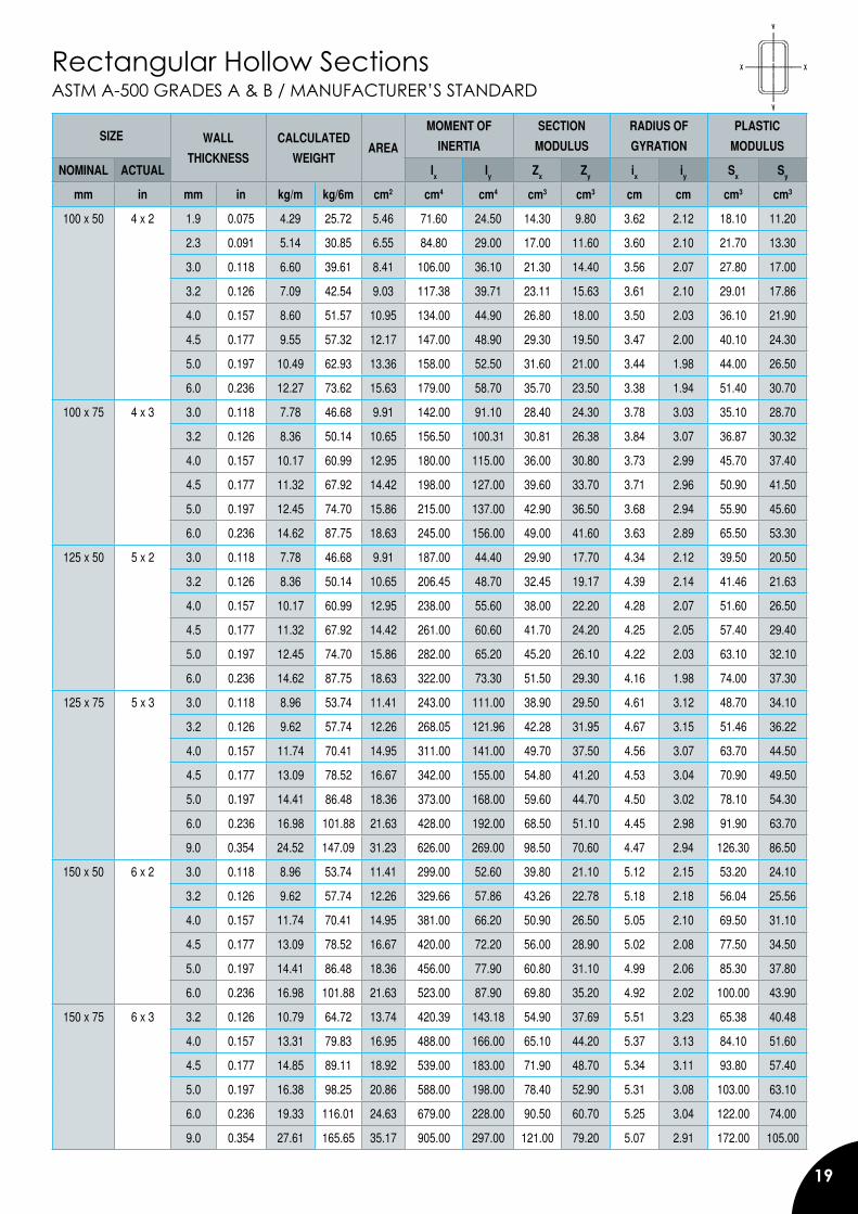
ASTM A-500 GRADES A & B / MANUFACTURER’S STANDARDRectangular Hollow Sections
SIZE WALL
THICKNESS
CALCULATED
WEIGHTAREA
MOMENT OF
INERTIA
SECTION
MODULUS
RADIUS OF
GYRATION
PLASTIC
MODULUS
NOMINAL ACTUAL Ix Iy Zx Zy ix iy Sx Sy
mm in mm in kg/m kg/6m cm2 cm4 cm4 cm3 cm3 cm cm cm3 cm3
100 x 50 4 x 2 1.9 0.075 4.29 25.72 5.46 71.60 24.50 14.30 9.80 3.62 2.12 18.10 11.20
2.3 0.091 5.14 30.85 6.55 84.80 29.00 17.00 11.60 3.60 2.10 21.70 13.30
3.0 0.118 6.60 39.61 8.41 106.00 36.10 21.30 14.40 3.56 2.07 27.80 17.00
3.2 0.126 7.09 42.54 9.03 117.38 39.71 23.11 15.63 3.61 2.10 29.01 17.86
4.0 0.157 8.60 51.57 10.95 134.00 44.90 26.80 18.00 3.50 2.03 36.10 21.90
4.5 0.177 9.55 57.32 12.17 147.00 48.90 29.30 19.50 3.47 2.00 40.10 24.30
5.0 0.197 10.49 62.93 13.36 158.00 52.50 31.60 21.00 3.44 1.98 44.00 26.50
6.0 0.236 12.27 73.62 15.63 179.00 58.70 35.70 23.50 3.38 1.94 51.40 30.70
100 x 75 4 x 3 3.0 0.118 7.78 46.68 9.91 142.00 91.10 28.40 24.30 3.78 3.03 35.10 28.70
3.2 0.126 8.36 50.14 10.65 156.50 100.31 30.81 26.38 3.84 3.07 36.87 30.32
4.0 0.157 10.17 60.99 12.95 180.00 115.00 36.00 30.80 3.73 2.99 45.70 37.40
4.5 0.177 11.32 67.92 14.42 198.00 127.00 39.60 33.70 3.71 2.96 50.90 41.50
5.0 0.197 12.45 74.70 15.86 215.00 137.00 42.90 36.50 3.68 2.94 55.90 45.60
6.0 0.236 14.62 87.75 18.63 245.00 156.00 49.00 41.60 3.63 2.89 65.50 53.30
125 x 50 5 x 2 3.0 0.118 7.78 46.68 9.91 187.00 44.40 29.90 17.70 4.34 2.12 39.50 20.50
3.2 0.126 8.36 50.14 10.65 206.45 48.70 32.45 19.17 4.39 2.14 41.46 21.63
4.0 0.157 10.17 60.99 12.95 238.00 55.60 38.00 22.20 4.28 2.07 51.60 26.50
4.5 0.177 11.32 67.92 14.42 261.00 60.60 41.70 24.20 4.25 2.05 57.40 29.40
5.0 0.197 12.45 74.70 15.86 282.00 65.20 45.20 26.10 4.22 2.03 63.10 32.10
6.0 0.236 14.62 87.75 18.63 322.00 73.30 51.50 29.30 4.16 1.98 74.00 37.30
125 x 75 5 x 3 3.0 0.118 8.96 53.74 11.41 243.00 111.00 38.90 29.50 4.61 3.12 48.70 34.10
3.2 0.126 9.62 57.74 12.26 268.05 121.96 42.28 31.95 4.67 3.15 51.46 36.22
4.0 0.157 11.74 70.41 14.95 311.00 141.00 49.70 37.50 4.56 3.07 63.70 44.50
4.5 0.177 13.09 78.52 16.67 342.00 155.00 54.80 41.20 4.53 3.04 70.90 49.50
5.0 0.197 14.41 86.48 18.36 373.00 168.00 59.60 44.70 4.50 3.02 78.10 54.30
6.0 0.236 16.98 101.88 21.63 428.00 192.00 68.50 51.10 4.45 2.98 91.90 63.70
9.0 0.354 24.52 147.09 31.23 626.00 269.00 98.50 70.60 4.47 2.94 126.30 86.50
150 x 50 6 x 2 3.0 0.118 8.96 53.74 11.41 299.00 52.60 39.80 21.10 5.12 2.15 53.20 24.10
3.2 0.126 9.62 57.74 12.26 329.66 57.86 43.26 22.78 5.18 2.18 56.04 25.56
4.0 0.157 11.74 70.41 14.95 381.00 66.20 50.90 26.50 5.05 2.10 69.50 31.10
4.5 0.177 13.09 78.52 16.67 420.00 72.20 56.00 28.90 5.02 2.08 77.50 34.50
5.0 0.197 14.41 86.48 18.36 456.00 77.90 60.80 31.10 4.99 2.06 85.30 37.80
6.0 0.236 16.98 101.88 21.63 523.00 87.90 69.80 35.20 4.92 2.02 100.00 43.90
150 x 75 6 x 3 3.2 0.126 10.79 64.72 13.74 420.39 143.18 54.90 37.69 5.51 3.23 65.38 40.48
4.0 0.157 13.31 79.83 16.95 488.00 166.00 65.10 44.20 5.37 3.13 84.10 51.60
4.5 0.177 14.85 89.11 18.92 539.00 183.00 71.90 48.70 5.34 3.11 93.80 57.40
5.0 0.197 16.38 98.25 20.86 588.00 198.00 78.40 52.90 5.31 3.08 103.00 63.10
6.0 0.236 19.33 116.01 24.63 679.00 228.00 90.50 60.70 5.25 3.04 122.00 74.00
9.0 0.354 27.61 165.65 35.17 905.00 297.00 121.00 79.20 5.07 2.91 172.00 105.00
20
ASTM A-500 GRADES A & B / MANUFACTURER’S STANDARDRectangular Hollow Sections
SIZE WALL
THICKNESS
CALCULATED
WEIGHTAREA
MOMENT OF
INERTIA
SECTION
MODULUS
RADIUS OF
GYRATION
PLASTIC
MODULUS
NOMINAL ACTUAL Ix Iy Zx Zy ix iy Sx Sy
mm in mm in kg/m kg/6m cm2 cm4 cm4 cm3 cm3 cm cm cm3 cm3
150 x 100 6 x 4 4.0 0.157 14.88 89.25 18.95 595.00 319.00 79.30 63.70 5.60 4.10 98.70 74.50
4.5 0.177 16.62 99.71 21.17 658.00 352.00 87.70 70.40 5.58 4.08 110.00 83.10
5.0 0.197 18.34 110.03 23.36 719.00 384.00 95.90 76.80 5.55 4.05 122.00 91.50
6.0 0.236 21.69 130.14 27.63 835.00 444.00 111.10 88.80 5.50 4.01 144.00 108.00
9.0 0.354 31.14 186.85 39.67 1129.00 595.00 150.50 119.00 5.33 3.87 190.00 143.00
175 x 100 7 x 4 4.5 0.177 18.43 110.61 23.48 1015.60 424.14 114.38 83.57 6.58 4.24 134.87 91.28
6.0 0.236 24.26 145.55 30.90 1298.64 536.94 146.01 105.53 6.45 4.17 177.31 119.30
9.0 0.354 34.69 208.15 44.19 1694.06 686.78 193.37 137.65 6.20 3.94 244.82 163.22
175 x 125 7 x 5 4.5 0.177 20.46 122.76 26.06 1194.58 707.59 134.37 111.76 6.73 5.21 159.94 126.84
6.0 0.236 26.74 160.44 34.06 1502.60 899.06 170.43 141.26 6.68 5.13 196.64 155.51
9.0 0.354 38.19 229.12 48.65 1985.42 1157.12 226.14 185.17 6.38 4.88 280.05 220.24
200 x 100 8 x 4 4.5 0.177 20.15 120.91 25.67 1331.00 455.00 133.00 90.90 7.20 4.21 170.00 105.00
5.0 0.197 22.26 133.58 28.36 1459.00 497.00 146.00 99.40 7.17 4.19 188.00 115.00
6.0 0.236 26.40 158.40 33.63 1703.00 577.00 170.00 115.00 7.12 4.14 222.00 136.00
9.0 0.354 37.68 226.08 48.00 2280.00 764.00 228.00 153.00 6.89 3.99 293.00 180.00
200 x 150 8 x 6 4.5 0.177 23.68 142.10 30.17 1761.60 1134.60 176.20 151.30 7.64 6.13 208.90 171.80
6.0 0.236 31.11 186.66 39.63 2268.10 1457.20 226.80 194.30 7.56 6.06 271.50 223.10
9.0 0.354 45.28 271.66 57.68 3167.30 2024.90 316.70 270.00 7.41 5.93 386.40 316.90
200 x 150 8 x 6 4.5 0.177 23.68 142.10 30.17 1761.60 1134.60 176.20 151.30 7.64 6.13 208.90 171.80
6.0 0.236 31.11 186.66 39.63 2268.10 1457.20 226.80 194.30 7.56 6.06 271.50 223.10
9.0 0.354 45.28 271.66 57.68 3167.30 2024.90 316.70 270.00 7.41 5.93 386.40 316.90
250 x 150 10 x 6 6.0 0.236 35.82 214.92 45.63 1768.40 3885.70 310.90 235.80 9.23 6.23 378.10 266.30
9.0 0.354 52.34 314.06 66.68 2472.80 5478.70 438.30 329.70 9.06 6.09 541.90 380.40
300 x 200 12 x 8 6.0 0.236 45.24 271.44 57.63 7370.50 3962.30 491.40 396.20 11.31 8.29 587.80 446.10
9.0 0.354 66.47 398.84 84.68 10529.50 5631.61 702.00 563.20 11.15 8.16 850.80 644.30
21
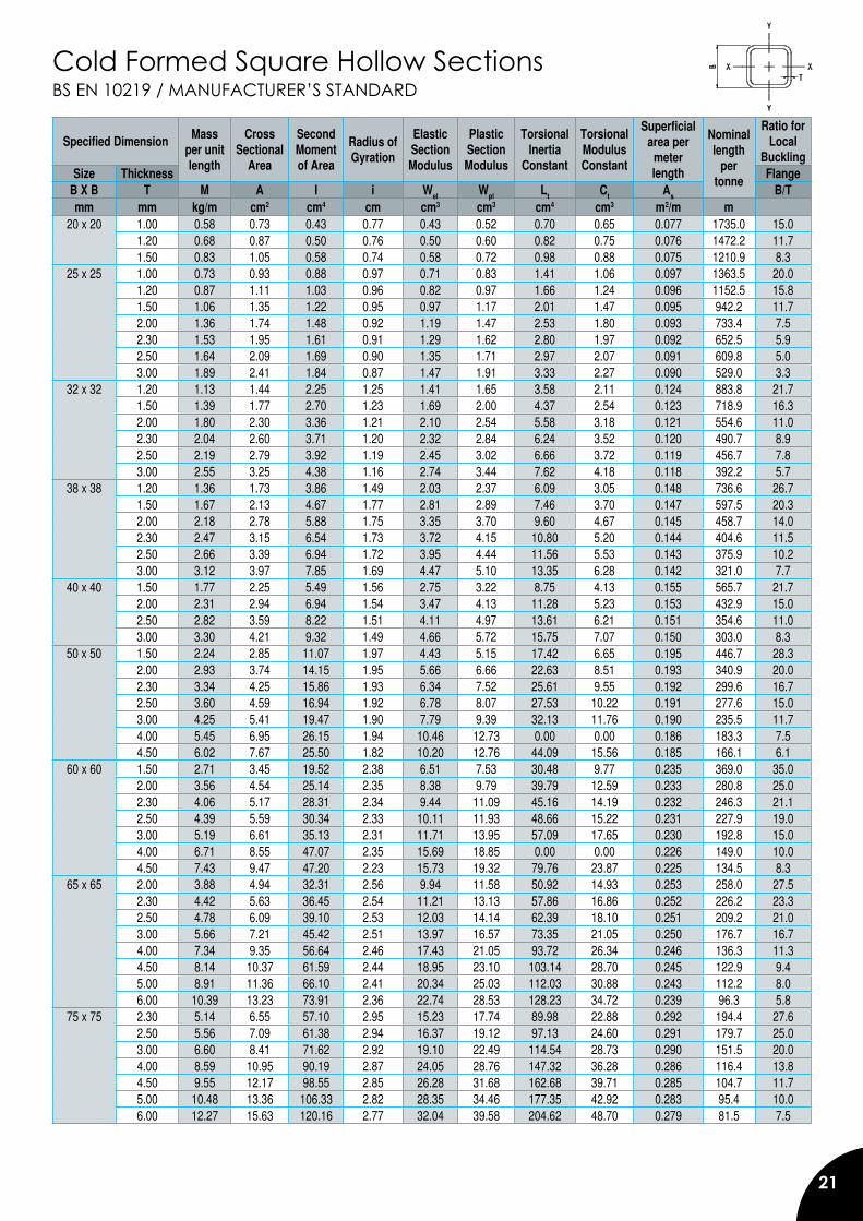
Cold Formed Square Hollow SectionsBS EN 10219 / MANUFACTURER’S STANDARD
Specified Dimension Mass per unit length
Cross Sectional
Area
Second Moment of Area
Radius of Gyration
Elastic Section Modulus
Plastic Section Modulus
Torsional Inertia
Constant
Torsional Modulus Constant
Superficial area per
meter length
Nominal length
per tonne
Ratio for Local
BucklingSize Thickness Flange
B X B T M A I i Wel Wpl Lt Ct As B/Tmm mm kg/m cm2 cm4 cm cm3 cm3 cm4 cm3 m2/m m
20 x 20 1.00 0.58 0.73 0.43 0.77 0.43 0.52 0.70 0.65 0.077 1735.0 15.01.20 0.68 0.87 0.50 0.76 0.50 0.60 0.82 0.75 0.076 1472.2 11.71.50 0.83 1.05 0.58 0.74 0.58 0.72 0.98 0.88 0.075 1210.9 8.3
25 x 25 1.00 0.73 0.93 0.88 0.97 0.71 0.83 1.41 1.06 0.097 1363.5 20.01.20 0.87 1.11 1.03 0.96 0.82 0.97 1.66 1.24 0.096 1152.5 15.81.50 1.06 1.35 1.22 0.95 0.97 1.17 2.01 1.47 0.095 942.2 11.72.00 1.36 1.74 1.48 0.92 1.19 1.47 2.53 1.80 0.093 733.4 7.52.30 1.53 1.95 1.61 0.91 1.29 1.62 2.80 1.97 0.092 652.5 5.92.50 1.64 2.09 1.69 0.90 1.35 1.71 2.97 2.07 0.091 609.8 5.03.00 1.89 2.41 1.84 0.87 1.47 1.91 3.33 2.27 0.090 529.0 3.3
32 x 32 1.20 1.13 1.44 2.25 1.25 1.41 1.65 3.58 2.11 0.124 883.8 21.71.50 1.39 1.77 2.70 1.23 1.69 2.00 4.37 2.54 0.123 718.9 16.32.00 1.80 2.30 3.36 1.21 2.10 2.54 5.58 3.18 0.121 554.6 11.02.30 2.04 2.60 3.71 1.20 2.32 2.84 6.24 3.52 0.120 490.7 8.92.50 2.19 2.79 3.92 1.19 2.45 3.02 6.66 3.72 0.119 456.7 7.83.00 2.55 3.25 4.38 1.16 2.74 3.44 7.62 4.18 0.118 392.2 5.7
38 x 38 1.20 1.36 1.73 3.86 1.49 2.03 2.37 6.09 3.05 0.148 736.6 26.71.50 1.67 2.13 4.67 1.77 2.81 2.89 7.46 3.70 0.147 597.5 20.32.00 2.18 2.78 5.88 1.75 3.35 3.70 9.60 4.67 0.145 458.7 14.02.30 2.47 3.15 6.54 1.73 3.72 4.15 10.80 5.20 0.144 404.6 11.52.50 2.66 3.39 6.94 1.72 3.95 4.44 11.56 5.53 0.143 375.9 10.23.00 3.12 3.97 7.85 1.69 4.47 5.10 13.35 6.28 0.142 321.0 7.7
40 x 40 1.50 1.77 2.25 5.49 1.56 2.75 3.22 8.75 4.13 0.155 565.7 21.72.00 2.31 2.94 6.94 1.54 3.47 4.13 11.28 5.23 0.153 432.9 15.02.50 2.82 3.59 8.22 1.51 4.11 4.97 13.61 6.21 0.151 354.6 11.03.00 3.30 4.21 9.32 1.49 4.66 5.72 15.75 7.07 0.150 303.0 8.3
50 x 50 1.50 2.24 2.85 11.07 1.97 4.43 5.15 17.42 6.65 0.195 446.7 28.32.00 2.93 3.74 14.15 1.95 5.66 6.66 22.63 8.51 0.193 340.9 20.02.30 3.34 4.25 15.86 1.93 6.34 7.52 25.61 9.55 0.192 299.6 16.72.50 3.60 4.59 16.94 1.92 6.78 8.07 27.53 10.22 0.191 277.6 15.03.00 4.25 5.41 19.47 1.90 7.79 9.39 32.13 11.76 0.190 235.5 11.74.00 5.45 6.95 26.15 1.94 10.46 12.73 0.00 0.00 0.186 183.3 7.54.50 6.02 7.67 25.50 1.82 10.20 12.76 44.09 15.56 0.185 166.1 6.1
60 x 60 1.50 2.71 3.45 19.52 2.38 6.51 7.53 30.48 9.77 0.235 369.0 35.02.00 3.56 4.54 25.14 2.35 8.38 9.79 39.79 12.59 0.233 280.8 25.02.30 4.06 5.17 28.31 2.34 9.44 11.09 45.16 14.19 0.232 246.3 21.12.50 4.39 5.59 30.34 2.33 10.11 11.93 48.66 15.22 0.231 227.9 19.03.00 5.19 6.61 35.13 2.31 11.71 13.95 57.09 17.65 0.230 192.8 15.04.00 6.71 8.55 47.07 2.35 15.69 18.85 0.00 0.00 0.226 149.0 10.04.50 7.43 9.47 47.20 2.23 15.73 19.32 79.76 23.87 0.225 134.5 8.3
65 x 65 2.00 3.88 4.94 32.31 2.56 9.94 11.58 50.92 14.93 0.253 258.0 27.52.30 4.42 5.63 36.45 2.54 11.21 13.13 57.86 16.86 0.252 226.2 23.32.50 4.78 6.09 39.10 2.53 12.03 14.14 62.39 18.10 0.251 209.2 21.03.00 5.66 7.21 45.42 2.51 13.97 16.57 73.35 21.05 0.250 176.7 16.74.00 7.34 9.35 56.64 2.46 17.43 21.05 93.72 26.34 0.246 136.3 11.34.50 8.14 10.37 61.59 2.44 18.95 23.10 103.14 28.70 0.245 122.9 9.45.00 8.91 11.36 66.10 2.41 20.34 25.03 112.03 30.88 0.243 112.2 8.06.00 10.39 13.23 73.91 2.36 22.74 28.53 128.23 34.72 0.239 96.3 5.8
75 x 75 2.30 5.14 6.55 57.10 2.95 15.23 17.74 89.98 22.88 0.292 194.4 27.62.50 5.56 7.09 61.38 2.94 16.37 19.12 97.13 24.60 0.291 179.7 25.03.00 6.60 8.41 71.62 2.92 19.10 22.49 114.54 28.73 0.290 151.5 20.04.00 8.59 10.95 90.19 2.87 24.05 28.76 147.32 36.28 0.286 116.4 13.84.50 9.55 12.17 98.55 2.85 26.28 31.68 162.68 39.71 0.285 104.7 11.75.00 10.48 13.36 106.33 2.82 28.35 34.46 177.35 42.92 0.283 95.4 10.06.00 12.27 15.63 120.16 2.77 32.04 39.58 204.62 48.70 0.279 81.5 7.5
22
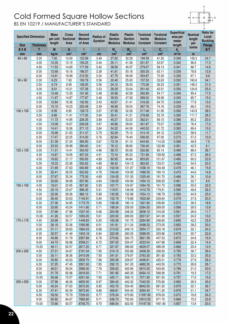
BS EN 10219 / MANUFACTURER’S STANDARDCold Formed Square Hollow Sections
Specified Dimension Mass per unit length
Cross Sectional
Area
Second Moment of Area
Radius of Gyration
Elastic Section Modulus
Plastic Section Modulus
Torsional Inertia
Constant
Torsional Modulus Constant
Superficial area per
meter length
Nominal length
per tonne
Ratio for Local
BucklingSize Thickness Flange
B X B T M A I i Wel Wpl Lt Ct As B/Tmm mm kg/m cm2 cm4 cm cm3 cm3 cm4 cm3 m2/m m
89 x 89 3.00 7.92 10.09 122.89 3.49 27.62 32.28 194.59 41.50 0.346 126.3 24.74.00 10.35 13.19 156.25 3.44 35.11 41.58 251.87 52.87 0.342 96.6 17.34.50 11.53 14.69 171.59 3.42 38.56 45.97 279.07 58.13 0.341 86.7 14.85.00 12.68 16.16 186.07 3.39 41.81 50.18 305.30 63.11 0.339 78.8 12.86.00 14.91 18.99 212.50 3.34 47.75 58.09 354.87 72.30 0.335 67.1 9.8
90 x 90 2.30 6.23 7.93 100.79 3.56 22.40 25.93 157.53 33.63 0.352 160.6 34.12.50 6.74 8.59 108.55 3.56 24.12 28.00 170.26 36.23 0.351 148.3 31.03.00 8.01 10.21 127.28 3.53 28.29 33.04 201.42 42.51 0.350 124.8 25.04.00 10.48 13.35 161.92 3.48 35.98 42.58 260.80 54.17 0.346 95.4 17.54.50 11.67 14.87 177.87 3.46 39.53 47.09 289.02 59.58 0.345 85.7 15.05.00 12.84 16.36 192.93 3.43 42.87 51.41 316.26 64.70 0.343 77.9 13.06.00 15.10 19.23 220.48 3.39 48.99 59.54 367.76 74.16 0.339 66.2 10.0
100 x 100 2.30 6.95 8.85 139.73 3.97 27.95 32.26 217.48 41.95 0.392 143.9 38.53.00 8.96 11.41 177.05 3.94 35.41 41.21 278.68 53.19 0.390 111.7 28.34.00 11.73 14.95 226.35 3.89 45.27 53.30 362.01 68.10 0.386 85.2 20.04.50 13.08 16.67 249.29 3.87 49.86 59.04 401.87 75.07 0.385 76.4 17.25.00 14.41 18.36 271.10 3.84 54.22 64.59 440.52 81.72 0.383 69.4 15.06.00 16.98 21.63 311.47 3.79 62.29 75.10 514.16 94.12 0.379 58.9 11.76.30 17.47 22.25 314.20 3.76 62.84 76.40 536.00 97.00 0.373 57.2 10.98.00 21.39 27.24 365.90 3.67 73.18 91.10 644.60 114.20 0.366 46.8 7.59.00 23.53 29.98 390.60 3.61 78.12 98.60 700.40 122.80 0.361 42.5 6.1
125 x 125 3.00 11.31 14.41 354.50 4.96 56.72 65.56 552.66 85.14 0.490 88.4 36.74.00 14.87 18.95 457.23 4.91 73.16 85.33 721.99 109.92 0.486 67.2 26.34.50 16.62 21.17 505.83 4.89 80.93 94.84 803.85 121.67 0.485 60.2 22.85.00 18.33 23.36 552.62 4.86 88.42 104.10 883.82 133.01 0.483 54.5 20.06.00 21.69 27.63 640.89 4.82 102.54 121.87 1038.10 154.49 0.479 46.1 15.86.30 22.41 28.55 652.60 4.78 104.42 124.90 1086.50 160.10 0.473 44.6 14.88.00 27.67 35.24 775.30 4.69 124.05 151.00 1325.40 191.70 0.466 36.1 10.69.00 30.60 38.98 837.80 4.64 134.05 164.90 1454.10 208.20 0.461 32.7 8.9
150 x 150 4.00 18.01 22.95 807.82 5.93 107.71 124.87 1264.76 161.73 0.586 55.5 32.54.50 20.15 25.67 896.30 5.91 119.51 139.08 1410.79 179.51 0.585 49.6 28.35.00 22.26 28.36 982.12 5.89 130.95 152.98 1554.13 196.79 0.583 44.9 25.06.00 26.40 33.63 1145.91 5.84 152.79 179.88 1832.69 229.84 0.579 37.9 20.06.30 27.36 34.85 1173.70 5.80 156.49 185.10 1921.60 238.80 0.573 36.5 18.88.00 33.95 43.24 1411.80 5.71 188.24 226.00 2364.20 289.00 0.566 29.5 13.89.00 37.66 47.98 1537.40 5.66 204.99 248.20 2608.10 316.00 0.561 26.6 11.710.00 41.26 52.57 1650.00 5.61 220.00 269.00 2837.67 341.00 0.557 24.2 10.0
175 x 175 4.50 23.68 30.17 1448.83 6.93 165.58 191.75 2264.90 248.60 0.685 42.2 33.95.00 26.18 33.36 1590.86 6.91 181.81 211.24 2498.33 273.05 0.683 38.2 30.06.00 31.11 39.63 1864.03 6.86 213.03 249.15 2954.17 320.18 0.679 32.1 24.26.30 32.57 41.49 1943.18 6.84 222.08 260.25 3088.05 333.86 0.678 30.7 22.88.00 40.66 51.79 2367.89 6.76 270.62 320.75 3821.58 407.53 0.673 24.6 16.99.00 44.73 56.98 2599.21 6.75 297.05 354.47 4233.04 447.88 0.669 22.4 14.410.00 49.11 62.57 2817.20 6.71 321.97 386.83 4629.57 486.09 0.666 20.4 12.5
200 x 200 4.50 27.21 34.67 2191.54 7.95 219.15 252.86 3408.36 328.93 0.785 36.7 39.45.00 30.11 38.36 2410.09 7.93 241.01 278.87 3763.30 361.82 0.783 33.2 35.06.00 35.82 45.63 2832.75 7.88 283.28 329.67 4458.81 425.51 0.779 27.9 28.36.30 37.25 47.45 2921.50 7.85 292.15 341.20 4682.20 443.50 0.773 26.8 26.78.00 46.51 59.24 3566.30 7.76 356.63 420.90 5815.30 543.60 0.766 21.5 20.09.00 51.79 65.98 3918.50 7.71 391.85 465.30 6454.10 598.90 0.761 19.3 17.210.00 56.96 72.57 4251.00 7.65 425.11 508.10 7071.90 651.50 0.757 17.6 15.0
250 x 250 5.00 37.96 48.36 4805.00 9.97 384.40 442.30 7443.00 576.80 0.983 26.3 45.06.00 45.24 57.63 5672.00 9.92 453.76 524.40 8842.50 681.20 0.979 22.1 36.76.30 47.41 60.39 5872.60 9.86 469.81 544.40 9290.40 711.20 0.978 21.1 34.78.00 59.50 75.79 7229.20 9.77 578.34 675.80 11597.90 878.20 0.973 16.8 26.39.00 65.92 84.67 7983.80 9.71 638.70 750.00 12913.50 971.70 0.969 15.0 22.810.00 72.66 92.57 8706.70 9.70 696.54 822.00 14197.50 1061.80 0.957 13.8 20.0
23
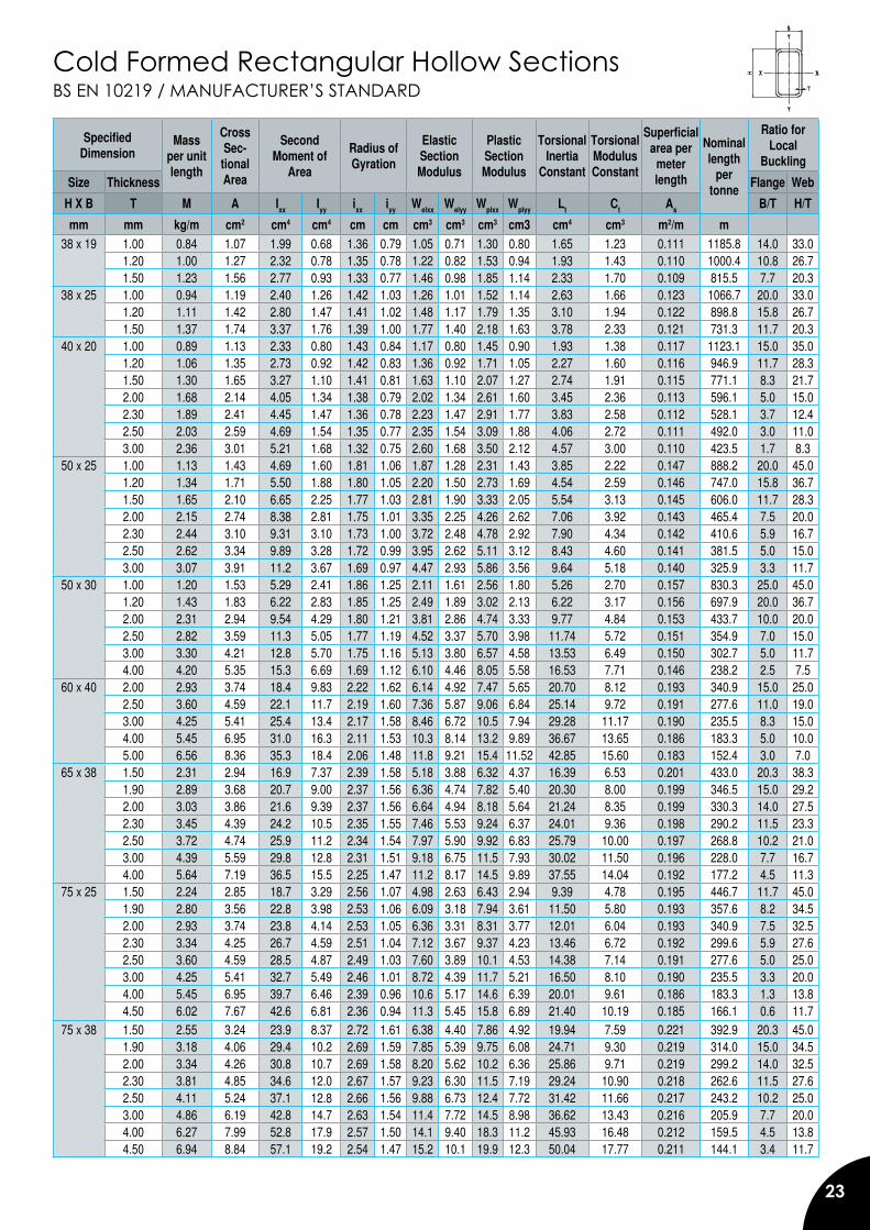
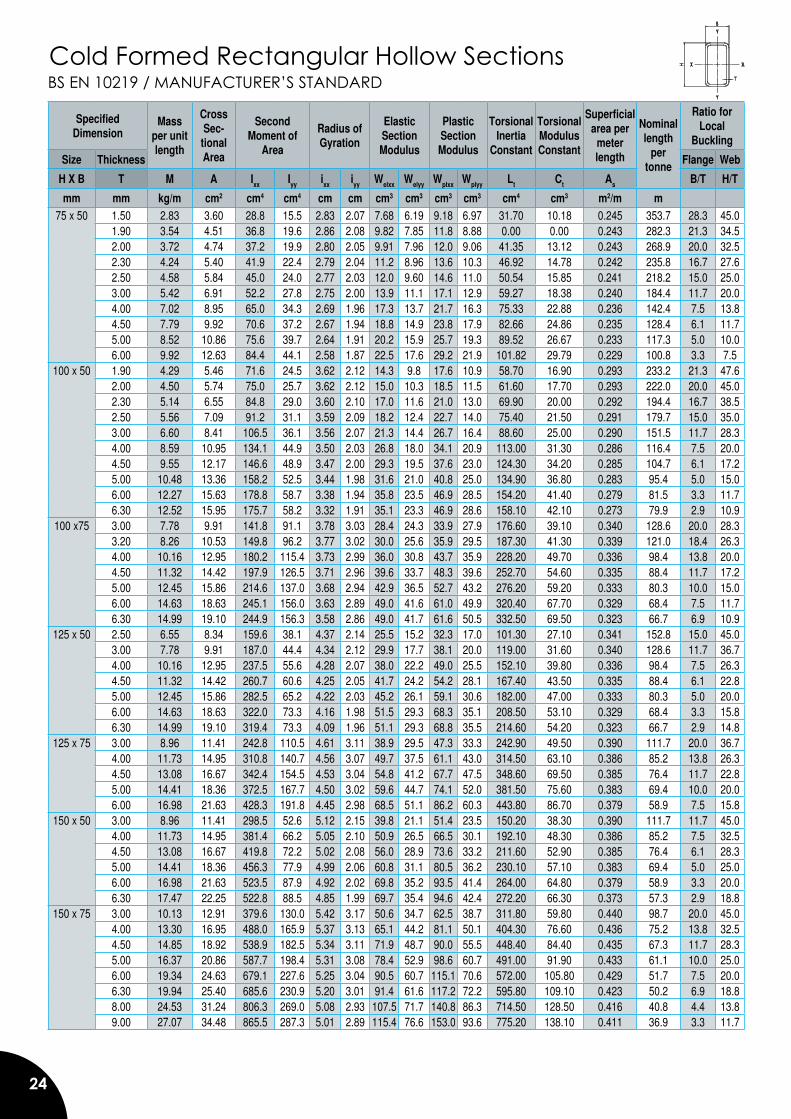
Cold Formed Rectangular Hollow SectionsBS EN 10219 / MANUFACTURER’S STANDARD
Specified Dimension
Mass per unitlength
CrossSec-
tionalArea
SecondMoment of
Area
Radius of Gyration
ElasticSection Modulus
PlasticSection Modulus
Torsional Inertia
Constant
TorsionalModulusConstant
Superficial area per
meter length
Nominal length
per tonne
Ratio forLocal
Buckling
Size Thickness Flange Web
H X B T M A Ixx Iyy ixx iyy Welxx Welyy Wplxx Wplyy Lt Ct As B/T H/T
mm mm kg/m cm2 cm4 cm4 cm cm cm3 cm3 cm3 cm3 cm4 cm3 m2/m m38 x 19 1.00 0.84 1.07 1.99 0.68 1.36 0.79 1.05 0.71 1.30 0.80 1.65 1.23 0.111 1185.8 14.0 33.0
1.20 1.00 1.27 2.32 0.78 1.35 0.78 1.22 0.82 1.53 0.94 1.93 1.43 0.110 1000.4 10.8 26.71.50 1.23 1.56 2.77 0.93 1.33 0.77 1.46 0.98 1.85 1.14 2.33 1.70 0.109 815.5 7.7 20.3
38 x 25 1.00 0.94 1.19 2.40 1.26 1.42 1.03 1.26 1.01 1.52 1.14 2.63 1.66 0.123 1066.7 20.0 33.01.20 1.11 1.42 2.80 1.47 1.41 1.02 1.48 1.17 1.79 1.35 3.10 1.94 0.122 898.8 15.8 26.71.50 1.37 1.74 3.37 1.76 1.39 1.00 1.77 1.40 2.18 1.63 3.78 2.33 0.121 731.3 11.7 20.3
40 x 20 1.00 0.89 1.13 2.33 0.80 1.43 0.84 1.17 0.80 1.45 0.90 1.93 1.38 0.117 1123.1 15.0 35.01.20 1.06 1.35 2.73 0.92 1.42 0.83 1.36 0.92 1.71 1.05 2.27 1.60 0.116 946.9 11.7 28.31.50 1.30 1.65 3.27 1.10 1.41 0.81 1.63 1.10 2.07 1.27 2.74 1.91 0.115 771.1 8.3 21.72.00 1.68 2.14 4.05 1.34 1.38 0.79 2.02 1.34 2.61 1.60 3.45 2.36 0.113 596.1 5.0 15.02.30 1.89 2.41 4.45 1.47 1.36 0.78 2.23 1.47 2.91 1.77 3.83 2.58 0.112 528.1 3.7 12.42.50 2.03 2.59 4.69 1.54 1.35 0.77 2.35 1.54 3.09 1.88 4.06 2.72 0.111 492.0 3.0 11.03.00 2.36 3.01 5.21 1.68 1.32 0.75 2.60 1.68 3.50 2.12 4.57 3.00 0.110 423.5 1.7 8.3
50 x 25 1.00 1.13 1.43 4.69 1.60 1.81 1.06 1.87 1.28 2.31 1.43 3.85 2.22 0.147 888.2 20.0 45.01.20 1.34 1.71 5.50 1.88 1.80 1.05 2.20 1.50 2.73 1.69 4.54 2.59 0.146 747.0 15.8 36.71.50 1.65 2.10 6.65 2.25 1.77 1.03 2.81 1.90 3.33 2.05 5.54 3.13 0.145 606.0 11.7 28.32.00 2.15 2.74 8.38 2.81 1.75 1.01 3.35 2.25 4.26 2.62 7.06 3.92 0.143 465.4 7.5 20.02.30 2.44 3.10 9.31 3.10 1.73 1.00 3.72 2.48 4.78 2.92 7.90 4.34 0.142 410.6 5.9 16.72.50 2.62 3.34 9.89 3.28 1.72 0.99 3.95 2.62 5.11 3.12 8.43 4.60 0.141 381.5 5.0 15.03.00 3.07 3.91 11.2 3.67 1.69 0.97 4.47 2.93 5.86 3.56 9.64 5.18 0.140 325.9 3.3 11.7
50 x 30 1.00 1.20 1.53 5.29 2.41 1.86 1.25 2.11 1.61 2.56 1.80 5.26 2.70 0.157 830.3 25.0 45.01.20 1.43 1.83 6.22 2.83 1.85 1.25 2.49 1.89 3.02 2.13 6.22 3.17 0.156 697.9 20.0 36.72.00 2.31 2.94 9.54 4.29 1.80 1.21 3.81 2.86 4.74 3.33 9.77 4.84 0.153 433.7 10.0 20.02.50 2.82 3.59 11.3 5.05 1.77 1.19 4.52 3.37 5.70 3.98 11.74 5.72 0.151 354.9 7.0 15.03.00 3.30 4.21 12.8 5.70 1.75 1.16 5.13 3.80 6.57 4.58 13.53 6.49 0.150 302.7 5.0 11.74.00 4.20 5.35 15.3 6.69 1.69 1.12 6.10 4.46 8.05 5.58 16.53 7.71 0.146 238.2 2.5 7.5
60 x 40 2.00 2.93 3.74 18.4 9.83 2.22 1.62 6.14 4.92 7.47 5.65 20.70 8.12 0.193 340.9 15.0 25.02.50 3.60 4.59 22.1 11.7 2.19 1.60 7.36 5.87 9.06 6.84 25.14 9.72 0.191 277.6 11.0 19.03.00 4.25 5.41 25.4 13.4 2.17 1.58 8.46 6.72 10.5 7.94 29.28 11.17 0.190 235.5 8.3 15.04.00 5.45 6.95 31.0 16.3 2.11 1.53 10.3 8.14 13.2 9.89 36.67 13.65 0.186 183.3 5.0 10.05.00 6.56 8.36 35.3 18.4 2.06 1.48 11.8 9.21 15.4 11.52 42.85 15.60 0.183 152.4 3.0 7.0
65 x 38 1.50 2.31 2.94 16.9 7.37 2.39 1.58 5.18 3.88 6.32 4.37 16.39 6.53 0.201 433.0 20.3 38.31.90 2.89 3.68 20.7 9.00 2.37 1.56 6.36 4.74 7.82 5.40 20.30 8.00 0.199 346.5 15.0 29.22.00 3.03 3.86 21.6 9.39 2.37 1.56 6.64 4.94 8.18 5.64 21.24 8.35 0.199 330.3 14.0 27.52.30 3.45 4.39 24.2 10.5 2.35 1.55 7.46 5.53 9.24 6.37 24.01 9.36 0.198 290.2 11.5 23.32.50 3.72 4.74 25.9 11.2 2.34 1.54 7.97 5.90 9.92 6.83 25.79 10.00 0.197 268.8 10.2 21.03.00 4.39 5.59 29.8 12.8 2.31 1.51 9.18 6.75 11.5 7.93 30.02 11.50 0.196 228.0 7.7 16.74.00 5.64 7.19 36.5 15.5 2.25 1.47 11.2 8.17 14.5 9.89 37.55 14.04 0.192 177.2 4.5 11.3
75 x 25 1.50 2.24 2.85 18.7 3.29 2.56 1.07 4.98 2.63 6.43 2.94 9.39 4.78 0.195 446.7 11.7 45.01.90 2.80 3.56 22.8 3.98 2.53 1.06 6.09 3.18 7.94 3.61 11.50 5.80 0.193 357.6 8.2 34.52.00 2.93 3.74 23.8 4.14 2.53 1.05 6.36 3.31 8.31 3.77 12.01 6.04 0.193 340.9 7.5 32.52.30 3.34 4.25 26.7 4.59 2.51 1.04 7.12 3.67 9.37 4.23 13.46 6.72 0.192 299.6 5.9 27.62.50 3.60 4.59 28.5 4.87 2.49 1.03 7.60 3.89 10.1 4.53 14.38 7.14 0.191 277.6 5.0 25.03.00 4.25 5.41 32.7 5.49 2.46 1.01 8.72 4.39 11.7 5.21 16.50 8.10 0.190 235.5 3.3 20.04.00 5.45 6.95 39.7 6.46 2.39 0.96 10.6 5.17 14.6 6.39 20.01 9.61 0.186 183.3 1.3 13.84.50 6.02 7.67 42.6 6.81 2.36 0.94 11.3 5.45 15.8 6.89 21.40 10.19 0.185 166.1 0.6 11.7
75 x 38 1.50 2.55 3.24 23.9 8.37 2.72 1.61 6.38 4.40 7.86 4.92 19.94 7.59 0.221 392.9 20.3 45.01.90 3.18 4.06 29.4 10.2 2.69 1.59 7.85 5.39 9.75 6.08 24.71 9.30 0.219 314.0 15.0 34.52.00 3.34 4.26 30.8 10.7 2.69 1.58 8.20 5.62 10.2 6.36 25.86 9.71 0.219 299.2 14.0 32.52.30 3.81 4.85 34.6 12.0 2.67 1.57 9.23 6.30 11.5 7.19 29.24 10.90 0.218 262.6 11.5 27.62.50 4.11 5.24 37.1 12.8 2.66 1.56 9.88 6.73 12.4 7.72 31.42 11.66 0.217 243.2 10.2 25.03.00 4.86 6.19 42.8 14.7 2.63 1.54 11.4 7.72 14.5 8.98 36.62 13.43 0.216 205.9 7.7 20.04.00 6.27 7.99 52.8 17.9 2.57 1.50 14.1 9.40 18.3 11.2 45.93 16.48 0.212 159.5 4.5 13.84.50 6.94 8.84 57.1 19.2 2.54 1.47 15.2 10.1 19.9 12.3 50.04 17.77 0.211 144.1 3.4 11.7
24
BS EN 10219 / MANUFACTURER’S STANDARDCold Formed Rectangular Hollow Sections
SpecifiedDimension
Mass per unitlength
CrossSec-
tionalArea
SecondMoment of
Area
Radius of Gyration
ElasticSection Modulus
PlasticSection Modulus
Torsional Inertia
Constant
TorsionalModulusConstant
Superficial area per
meter length
Nominal length
per tonne
Ratio forLocal
Buckling
Size Thickness Flange Web
H X B T M A Ixx Iyy ixx iyy Welxx Welyy Wplxx Wplyy Lt Ct As B/T H/T
mm mm kg/m cm2 cm4 cm4 cm cm cm3 cm3 cm3 cm3 cm4 cm3 m2/m m75 x 50 1.50 2.83 3.60 28.8 15.5 2.83 2.07 7.68 6.19 9.18 6.97 31.70 10.18 0.245 353.7 28.3 45.0
1.90 3.54 4.51 36.8 19.6 2.86 2.08 9.82 7.85 11.8 8.88 0.00 0.00 0.243 282.3 21.3 34.52.00 3.72 4.74 37.2 19.9 2.80 2.05 9.91 7.96 12.0 9.06 41.35 13.12 0.243 268.9 20.0 32.52.30 4.24 5.40 41.9 22.4 2.79 2.04 11.2 8.96 13.6 10.3 46.92 14.78 0.242 235.8 16.7 27.62.50 4.58 5.84 45.0 24.0 2.77 2.03 12.0 9.60 14.6 11.0 50.54 15.85 0.241 218.2 15.0 25.03.00 5.42 6.91 52.2 27.8 2.75 2.00 13.9 11.1 17.1 12.9 59.27 18.38 0.240 184.4 11.7 20.04.00 7.02 8.95 65.0 34.3 2.69 1.96 17.3 13.7 21.7 16.3 75.33 22.88 0.236 142.4 7.5 13.84.50 7.79 9.92 70.6 37.2 2.67 1.94 18.8 14.9 23.8 17.9 82.66 24.86 0.235 128.4 6.1 11.75.00 8.52 10.86 75.6 39.7 2.64 1.91 20.2 15.9 25.7 19.3 89.52 26.67 0.233 117.3 5.0 10.06.00 9.92 12.63 84.4 44.1 2.58 1.87 22.5 17.6 29.2 21.9 101.82 29.79 0.229 100.8 3.3 7.5
100 x 50 1.90 4.29 5.46 71.6 24.5 3.62 2.12 14.3 9.8 17.6 10.9 58.70 16.90 0.293 233.2 21.3 47.62.00 4.50 5.74 75.0 25.7 3.62 2.12 15.0 10.3 18.5 11.5 61.60 17.70 0.293 222.0 20.0 45.02.30 5.14 6.55 84.8 29.0 3.60 2.10 17.0 11.6 21.0 13.0 69.90 20.00 0.292 194.4 16.7 38.52.50 5.56 7.09 91.2 31.1 3.59 2.09 18.2 12.4 22.7 14.0 75.40 21.50 0.291 179.7 15.0 35.03.00 6.60 8.41 106.5 36.1 3.56 2.07 21.3 14.4 26.7 16.4 88.60 25.00 0.290 151.5 11.7 28.34.00 8.59 10.95 134.1 44.9 3.50 2.03 26.8 18.0 34.1 20.9 113.00 31.30 0.286 116.4 7.5 20.04.50 9.55 12.17 146.6 48.9 3.47 2.00 29.3 19.5 37.6 23.0 124.30 34.20 0.285 104.7 6.1 17.25.00 10.48 13.36 158.2 52.5 3.44 1.98 31.6 21.0 40.8 25.0 134.90 36.80 0.283 95.4 5.0 15.06.00 12.27 15.63 178.8 58.7 3.38 1.94 35.8 23.5 46.9 28.5 154.20 41.40 0.279 81.5 3.3 11.76.30 12.52 15.95 175.7 58.2 3.32 1.91 35.1 23.3 46.9 28.6 158.10 42.10 0.273 79.9 2.9 10.9
100 x75 3.00 7.78 9.91 141.8 91.1 3.78 3.03 28.4 24.3 33.9 27.9 176.60 39.10 0.340 128.6 20.0 28.33.20 8.26 10.53 149.8 96.2 3.77 3.02 30.0 25.6 35.9 29.5 187.30 41.30 0.339 121.0 18.4 26.34.00 10.16 12.95 180.2 115.4 3.73 2.99 36.0 30.8 43.7 35.9 228.20 49.70 0.336 98.4 13.8 20.04.50 11.32 14.42 197.9 126.5 3.71 2.96 39.6 33.7 48.3 39.6 252.70 54.60 0.335 88.4 11.7 17.25.00 12.45 15.86 214.6 137.0 3.68 2.94 42.9 36.5 52.7 43.2 276.20 59.20 0.333 80.3 10.0 15.06.00 14.63 18.63 245.1 156.0 3.63 2.89 49.0 41.6 61.0 49.9 320.40 67.70 0.329 68.4 7.5 11.76.30 14.99 19.10 244.9 156.3 3.58 2.86 49.0 41.7 61.6 50.5 332.50 69.50 0.323 66.7 6.9 10.9
125 x 50 2.50 6.55 8.34 159.6 38.1 4.37 2.14 25.5 15.2 32.3 17.0 101.30 27.10 0.341 152.8 15.0 45.03.00 7.78 9.91 187.0 44.4 4.34 2.12 29.9 17.7 38.1 20.0 119.00 31.60 0.340 128.6 11.7 36.74.00 10.16 12.95 237.5 55.6 4.28 2.07 38.0 22.2 49.0 25.5 152.10 39.80 0.336 98.4 7.5 26.34.50 11.32 14.42 260.7 60.6 4.25 2.05 41.7 24.2 54.2 28.1 167.40 43.50 0.335 88.4 6.1 22.85.00 12.45 15.86 282.5 65.2 4.22 2.03 45.2 26.1 59.1 30.6 182.00 47.00 0.333 80.3 5.0 20.06.00 14.63 18.63 322.0 73.3 4.16 1.98 51.5 29.3 68.3 35.1 208.50 53.10 0.329 68.4 3.3 15.86.30 14.99 19.10 319.4 73.3 4.09 1.96 51.1 29.3 68.8 35.5 214.60 54.20 0.323 66.7 2.9 14.8
125 x 75 3.00 8.96 11.41 242.8 110.5 4.61 3.11 38.9 29.5 47.3 33.3 242.90 49.50 0.390 111.7 20.0 36.74.00 11.73 14.95 310.8 140.7 4.56 3.07 49.7 37.5 61.1 43.0 314.50 63.10 0.386 85.2 13.8 26.34.50 13.08 16.67 342.4 154.5 4.53 3.04 54.8 41.2 67.7 47.5 348.60 69.50 0.385 76.4 11.7 22.85.00 14.41 18.36 372.5 167.7 4.50 3.02 59.6 44.7 74.1 52.0 381.50 75.60 0.383 69.4 10.0 20.06.00 16.98 21.63 428.3 191.8 4.45 2.98 68.5 51.1 86.2 60.3 443.80 86.70 0.379 58.9 7.5 15.8
150 x 50 3.00 8.96 11.41 298.5 52.6 5.12 2.15 39.8 21.1 51.4 23.5 150.20 38.30 0.390 111.7 11.7 45.04.00 11.73 14.95 381.4 66.2 5.05 2.10 50.9 26.5 66.5 30.1 192.10 48.30 0.386 85.2 7.5 32.54.50 13.08 16.67 419.8 72.2 5.02 2.08 56.0 28.9 73.6 33.2 211.60 52.90 0.385 76.4 6.1 28.35.00 14.41 18.36 456.3 77.9 4.99 2.06 60.8 31.1 80.5 36.2 230.10 57.10 0.383 69.4 5.0 25.06.00 16.98 21.63 523.5 87.9 4.92 2.02 69.8 35.2 93.5 41.4 264.00 64.80 0.379 58.9 3.3 20.06.30 17.47 22.25 522.8 88.5 4.85 1.99 69.7 35.4 94.6 42.4 272.20 66.30 0.373 57.3 2.9 18.8
150 x 75 3.00 10.13 12.91 379.6 130.0 5.42 3.17 50.6 34.7 62.5 38.7 311.80 59.80 0.440 98.7 20.0 45.04.00 13.30 16.95 488.0 165.9 5.37 3.13 65.1 44.2 81.1 50.1 404.30 76.60 0.436 75.2 13.8 32.54.50 14.85 18.92 538.9 182.5 5.34 3.11 71.9 48.7 90.0 55.5 448.40 84.40 0.435 67.3 11.7 28.35.00 16.37 20.86 587.7 198.4 5.31 3.08 78.4 52.9 98.6 60.7 491.00 91.90 0.433 61.1 10.0 25.06.00 19.34 24.63 679.1 227.6 5.25 3.04 90.5 60.7 115.1 70.6 572.00 105.80 0.429 51.7 7.5 20.06.30 19.94 25.40 685.6 230.9 5.20 3.01 91.4 61.6 117.2 72.2 595.80 109.10 0.423 50.2 6.9 18.88.00 24.53 31.24 806.3 269.0 5.08 2.93 107.5 71.7 140.8 86.3 714.50 128.50 0.416 40.8 4.4 13.89.00 27.07 34.48 865.5 287.3 5.01 2.89 115.4 76.6 153.0 93.6 775.20 138.10 0.411 36.9 3.3 11.7
25
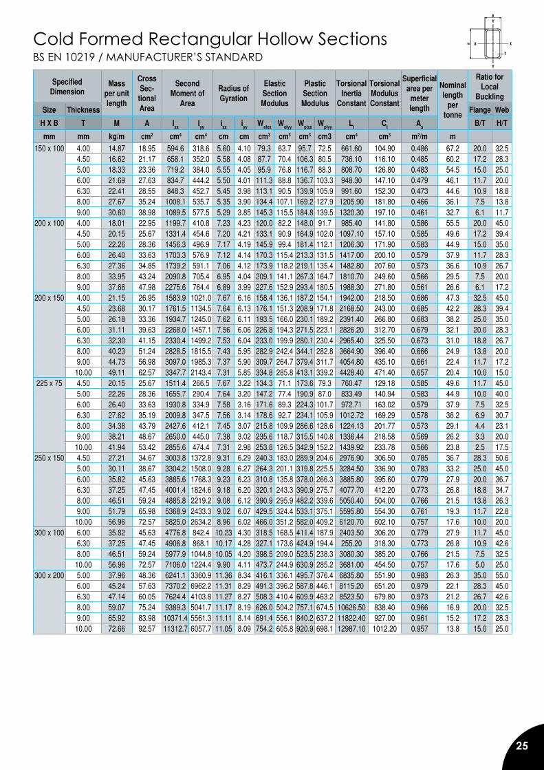
BS EN 10219 / MANUFACTURER’S STANDARDCold Formed Rectangular Hollow Sections
SpecifiedDimension
Mass per unitlength
CrossSec-
tionalArea
SecondMoment of
Area
Radius of Gyration
ElasticSection Modulus
PlasticSection Modulus
Torsional Inertia
Constant
TorsionalModulusConstant
Superficial area per
meter length
Nominal length
per tonne
Ratio forLocal
Buckling
Size Thickness Flange Web
H X B T M A Ixx Iyy ixx iyy Welxx Welyy Wplxx Wplyy Lt Ct As B/T H/T
mm mm kg/m cm2 cm4 cm4 cm cm cm3 cm3 cm3 cm3 cm4 cm3 m2/m m150 x 100 4.00 14.87 18.95 594.6 318.6 5.60 4.10 79.3 63.7 95.7 72.5 661.60 104.90 0.486 67.2 20.0 32.5
4.50 16.62 21.17 658.1 352.0 5.58 4.08 87.7 70.4 106.3 80.5 736.10 116.10 0.485 60.2 17.2 28.35.00 18.33 23.36 719.2 384.0 5.55 4.05 95.9 76.8 116.7 88.3 808.70 126.80 0.483 54.5 15.0 25.06.00 21.69 27.63 834.7 444.2 5.50 4.01 111.3 88.8 136.7 103.3 948.30 147.10 0.479 46.1 11.7 20.06.30 22.41 28.55 848.3 452.7 5.45 3.98 113.1 90.5 139.9 105.9 991.60 152.30 0.473 44.6 10.9 18.88.00 27.67 35.24 1008.1 535.7 5.35 3.90 134.4 107.1 169.2 127.9 1205.90 181.80 0.466 36.1 7.5 13.89.00 30.60 38.98 1089.5 577.5 5.29 3.85 145.3 115.5 184.8 139.5 1320.30 197.10 0.461 32.7 6.1 11.7
200 x 100 4.00 18.01 22.95 1199.7 410.8 7.23 4.23 120.0 82.2 148.0 91.7 985.40 141.80 0.586 55.5 20.0 45.04.50 20.15 25.67 1331.4 454.6 7.20 4.21 133.1 90.9 164.9 102.0 1097.10 157.10 0.585 49.6 17.2 39.45.00 22.26 28.36 1456.3 496.9 7.17 4.19 145.9 99.4 181.4 112.1 1206.30 171.90 0.583 44.9 15.0 35.06.00 26.40 33.63 1703.3 576.9 7.12 4.14 170.3 115.4 213.3 131.5 1417.00 200.10 0.579 37.9 11.7 28.36.30 27.36 34.85 1739.2 591.1 7.06 4.12 173.9 118.2 219.1 135.4 1482.80 207.60 0.573 36.6 10.9 26.78.00 33.95 43.24 2090.8 705.4 6.95 4.04 209.1 141.1 267.3 164.7 1810.70 249.60 0.566 29.5 7.5 20.09.00 37.66 47.98 2275.6 764.4 6.89 3.99 227.6 152.9 293.4 180.5 1988.30 271.80 0.561 26.6 6.1 17.2
200 x 150 4.00 21.15 26.95 1583.9 1021.0 7.67 6.16 158.4 136.1 187.2 154.1 1942.00 218.50 0.686 47.3 32.5 45.04.50 23.68 30.17 1761.5 1134.5 7.64 6.13 176.1 151.3 208.9 171.8 2168.50 243.00 0.685 42.2 28.3 39.45.00 26.18 33.36 1934.7 1245.0 7.62 6.11 193.5 166.0 230.1 189.2 2391.40 266.80 0.683 38.2 25.0 35.06.00 31.11 39.63 2268.0 1457.1 7.56 6.06 226.8 194.3 271.5 223.1 2826.20 312.70 0.679 32.1 20.0 28.36.30 32.30 41.15 2330.4 1499.2 7.53 6.04 233.0 199.9 280.1 230.4 2965.40 325.50 0.673 31.0 18.8 26.78.00 40.23 51.24 2828.5 1815.5 7.43 5.95 282.9 242.4 344.1 282.8 3664.90 396.40 0.666 24.9 13.8 20.09.00 44.73 56.98 3097.0 1985.3 7.37 5.90 309.7 264.7 379.4 311.7 4054.80 435.10 0.661 22.4 11.7 17.2
10.00 49.11 62.57 3347.7 2143.4 7.31 5.85 334.8 285.8 413.1 339.2 4428.40 471.40 0.657 20.4 10.0 15.0225 x 75 4.50 20.15 25.67 1511.4 266.5 7.67 3.22 134.3 71.1 173.6 79.3 760.47 129.18 0.585 49.6 11.7 45.0
5.00 22.26 28.36 1655.7 290.4 7.64 3.20 147.2 77.4 190.9 87.0 833.49 140.94 0.583 44.9 10.0 40.06.00 26.40 33.63 1930.8 334.9 7.58 3.16 171.6 89.3 224.3 101.7 972.71 163.02 0.579 37.9 7.5 32.56.30 27.62 35.19 2009.8 347.5 7.56 3.14 178.6 92.7 234.1 105.9 1012.72 169.29 0.578 36.2 6.9 30.78.00 34.38 43.79 2427.6 412.1 7.45 3.07 215.8 109.9 286.6 128.6 1224.13 201.77 0.573 29.1 4.4 23.19.00 38.21 48.67 2650.0 445.0 7.38 3.02 235.6 118.7 315.5 140.8 1336.44 218.58 0.569 26.2 3.3 20.0
10.00 41.94 53.42 2855.6 474.4 7.31 2.98 253.8 126.5 342.9 152.2 1439.92 233.78 0.566 23.8 2.5 17.5250 x 150 4.50 27.21 34.67 3003.8 1372.8 9.31 6.29 240.3 183.0 289.9 204.6 2976.90 306.50 0.785 36.7 28.3 50.6
5.00 30.11 38.67 3304.2 1508.0 9.28 6.27 264.3 201.1 319.8 225.5 3284.50 336.90 0.783 33.2 25.0 45.06.00 35.82 45.63 3885.6 1768.3 9.23 6.23 310.8 135.8 378.0 266.3 3885.80 395.60 0.779 27.9 20.0 36.76.30 37.25 47.45 4001.4 1824.6 9.18 6.20 320.1 243.3 390.9 275.7 4077.70 412.20 0.773 26.8 18.8 34.78.00 46.51 59.24 4885.8 2219.2 9.08 6.12 390.9 295.9 482.2 339.6 5050.40 504.00 0.766 21.5 13.8 26.39.00 51.79 65.98 5368.9 2433.3 9.02 6.07 429.5 324.4 533.1 375.1 5595.80 554.30 0.761 19.3 11.7 22.8
10.00 56.96 72.57 5825.0 2634.2 8.96 6.02 466.0 351.2 582.0 409.2 6120.70 602.10 0.757 17.6 10.0 20.0300 x 100 6.00 35.82 45.63 4776.8 842.4 10.23 4.30 318.5 168.5 411.4 187.9 2403.50 306.20 0.779 27.9 11.7 45.0
6.30 37.25 47.45 4906.8 868.1 10.17 4.28 327.1 173.6 424.9 194.4 255.20 318.30 0.773 26.8 10.9 42.68.00 46.51 59.24 5977.9 1044.8 10.05 4.20 398.5 209.0 523.5 238.3 3080.30 385.20 0.766 21.5 7.5 32.5
10.00 56.96 72.57 7106.0 1224.4 9.90 4.11 473.7 244.9 630.9 285.2 3681.00 454.50 0.757 17.6 5.0 25.0300 x 200 5.00 37.96 48.36 6241.1 3360.9 11.36 8.34 416.1 336.1 495.7 376.4 6835.80 551.90 0.983 26.3 35.0 55.0
6.00 45.24 57.63 7370.2 6962.2 11.31 8.29 491.3 396.2 587.8 446.1 8115.20 651.20 0.979 22.1 28.3 45.06.30 47.14 60.05 7624.4 4103.8 11.27 8.27 508.3 410.4 609.9 463.2 8523.50 679.80 0.973 21.2 26.7 42.68.00 59.07 75.24 9389.3 5041.7 11.17 8.19 626.0 504.2 757.1 674.5 10626.50 838.40 0.966 16.9 20.0 32.59.00 65.92 83.98 10371.4 5561.3 11.11 8.14 691.4 556.1 840.2 637.2 11822.40 927.00 0.961 15.2 17.2 28.3
10.00 72.66 92.57 11312.7 6057.7 11.05 8.09 754.2 605.8 920.9 698.1 12987.10 1012.20 0.957 13.8 15.0 25.0
26
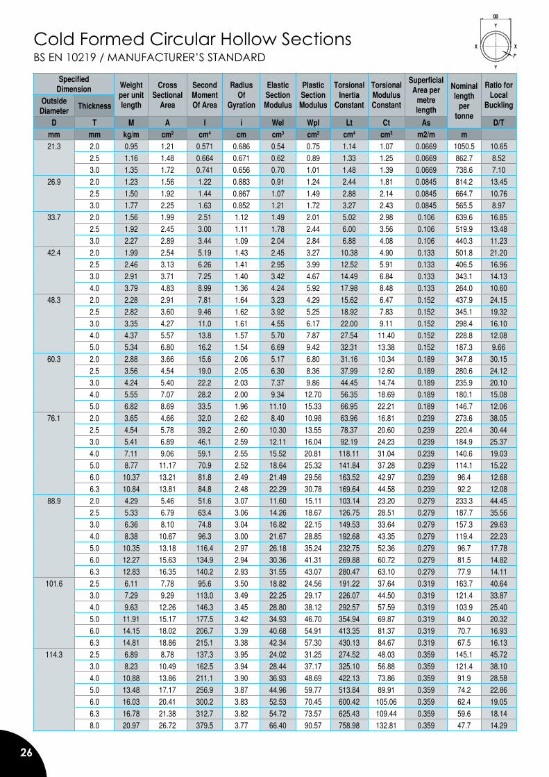
Cold Formed Circular Hollow SectionsBS EN 10219 / MANUFACTURER’S STANDARD
Specified Dimension Weight
per unit length
Cross Sectional
Area
Second Moment Of Area
Radius Of
Gyration
Elastic Section Modulus
Plastic Section Modulus
Torsional Inertia
Constant
Torsional Modulus Constant
Superficial Area per
metre length
Nominal length
per tonne
Ratio for Local
BucklingOutside Diameter
Thickness
D T M A I i Wel Wpl Lt Ct As D/Tmm mm kg/m cm2 cm4 cm cm3 cm3 cm4 cm3 m2/m m21.3 2.0 0.95 1.21 0.571 0.686 0.54 0.75 1.14 1.07 0.0669 1050.5 10.65
2.5 1.16 1.48 0.664 0.671 0.62 0.89 1.33 1.25 0.0669 862.7 8.523.0 1.35 1.72 0.741 0.656 0.70 1.01 1.48 1.39 0.0669 738.6 7.10
26.9 2.0 1.23 1.56 1.22 0.883 0.91 1.24 2.44 1.81 0.0845 814.2 13.452.5 1.50 1.92 1.44 0.867 1.07 1.49 2.88 2.14 0.0845 664.7 10.763.0 1.77 2.25 1.63 0.852 1.21 1.72 3.27 2.43 0.0845 565.5 8.97
33.7 2.0 1.56 1.99 2.51 1.12 1.49 2.01 5.02 2.98 0.106 639.6 16.852.5 1.92 2.45 3.00 1.11 1.78 2.44 6.00 3.56 0.106 519.9 13.483.0 2.27 2.89 3.44 1.09 2.04 2.84 6.88 4.08 0.106 440.3 11.23
42.4 2.0 1.99 2.54 5.19 1.43 2.45 3.27 10.38 4.90 0.133 501.8 21.202.5 2.46 3.13 6.26 1.41 2.95 3.99 12.52 5.91 0.133 406.5 16.963.0 2.91 3.71 7.25 1.40 3.42 4.67 14.49 6.84 0.133 343.1 14.134.0 3.79 4.83 8.99 1.36 4.24 5.92 17.98 8.48 0.133 264.0 10.60
48.3 2.0 2.28 2.91 7.81 1.64 3.23 4.29 15.62 6.47 0.152 437.9 24.152.5 2.82 3.60 9.46 1.62 3.92 5.25 18.92 7.83 0.152 345.1 19.323.0 3.35 4.27 11.0 1.61 4.55 6.17 22.00 9.11 0.152 298.4 16.104.0 4.37 5.57 13.8 1.57 5.70 7.87 27.54 11.40 0.152 228.8 12.085.0 5.34 6.80 16.2 1.54 6.69 9.42 32.31 13.38 0.152 187.3 9.66
60.3 2.0 2.88 3.66 15.6 2.06 5.17 6.80 31.16 10.34 0.189 347.8 30.152.5 3.56 4.54 19.0 2.05 6.30 8.36 37.99 12.60 0.189 280.6 24.123.0 4.24 5.40 22.2 2.03 7.37 9.86 44.45 14.74 0.189 235.9 20.104.0 5.55 7.07 28.2 2.00 9.34 12.70 56.35 18.69 0.189 180.1 15.085.0 6.82 8.69 33.5 1.96 11.10 15.33 66.95 22.21 0.189 146.7 12.06
76.1 2.0 3.65 4.66 32.0 2.62 8.40 10.98 63.96 16.81 0.239 273.6 38.052.5 4.54 5.78 39.2 2.60 10.30 13.55 78.37 20.60 0.239 220.4 30.443.0 5.41 6.89 46.1 2.59 12.11 16.04 92.19 24.23 0.239 184.9 25.374.0 7.11 9.06 59.1 2.55 15.52 20.81 118.11 31.04 0.239 140.6 19.035.0 8.77 11.17 70.9 2.52 18.64 25.32 141.84 37.28 0.239 114.1 15.226.0 10.37 13.21 81.8 2.49 21.49 29.56 163.52 42.97 0.239 96.4 12.686.3 10.84 13.81 84.8 2.48 22.29 30.78 169.64 44.58 0.239 92.2 12.08
88.9 2.0 4.29 5.46 51.6 3.07 11.60 15.11 103.14 23.20 0.279 233.3 44.452.5 5.33 6.79 63.4 3.06 14.26 18.67 126.75 28.51 0.279 187.7 35.563.0 6.36 8.10 74.8 3.04 16.82 22.15 149.53 33.64 0.279 157.3 29.634.0 8.38 10.67 96.3 3.00 21.67 28.85 192.68 43.35 0.279 119.4 22.235.0 10.35 13.18 116.4 2.97 26.18 35.24 232.75 52.36 0.279 96.7 17.786.0 12.27 15.63 134.9 2.94 30.36 41.31 269.88 60.72 0.279 81.5 14.826.3 12.83 16.35 140.2 2.93 31.55 43.07 280.47 63.10 0.279 77.9 14.11
101.6 2.5 6.11 7.78 95.6 3.50 18.82 24.56 191.22 37.64 0.319 163.7 40.643.0 7.29 9.29 113.0 3.49 22.25 29.17 226.07 44.50 0.319 121.4 33.874.0 9.63 12.26 146.3 3.45 28.80 38.12 292.57 57.59 0.319 103.9 25.405.0 11.91 15.17 177.5 3.42 34.93 46.70 354.94 69.87 0.319 84.0 20.326.0 14.15 18.02 206.7 3.39 40.68 54.91 413.35 81.37 0.319 70.7 16.936.3 14.81 18.86 215.1 3.38 42.34 57.30 430.13 84.67 0.319 67.5 16.13
114.3 2.5 6.89 8.78 137.3 3.95 24.02 31.25 274.52 48.03 0.359 145.1 45.723.0 8.23 10.49 162.5 3.94 28.44 37.17 325.10 56.88 0.359 121.4 38.104.0 10.88 13.86 211.1 3.90 36.93 48.69 422.13 73.86 0.359 91.9 28.585.0 13.48 17.17 256.9 3.87 44.96 59.77 513.84 89.91 0.359 74.2 22.866.0 16.03 20.41 300.2 3.83 52.53 70.45 600.42 105.06 0.359 62.4 19.056.3 16.78 21.38 312.7 3.82 54.72 73.57 625.43 109.44 0.359 59.6 18.148.0 20.97 26.72 379.5 3.77 66.40 90.57 758.98 132.81 0.359 47.7 14.29
27
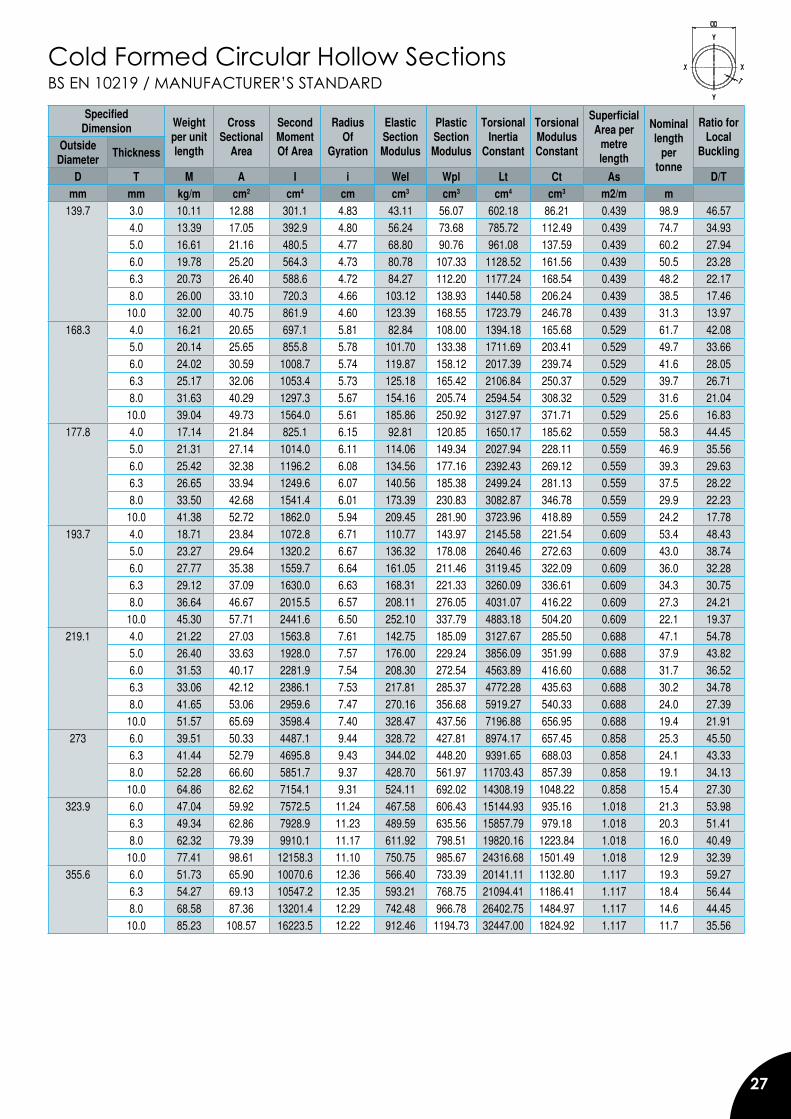
Cold Formed Circular Hollow SectionsBS EN 10219 / MANUFACTURER’S STANDARD
Specified Dimension Weight
per unit length
Cross Sectional
Area
Second Moment Of Area
Radius Of
Gyration
Elastic Section Modulus
Plastic Section Modulus
Torsional Inertia
Constant
Torsional Modulus Constant
Superficial Area per
metre length
Nominal length
per tonne
Ratio for Local
BucklingOutside Diameter
Thickness
D T M A I i Wel Wpl Lt Ct As D/Tmm mm kg/m cm2 cm4 cm cm3 cm3 cm4 cm3 m2/m m
139.7 3.0 10.11 12.88 301.1 4.83 43.11 56.07 602.18 86.21 0.439 98.9 46.574.0 13.39 17.05 392.9 4.80 56.24 73.68 785.72 112.49 0.439 74.7 34.935.0 16.61 21.16 480.5 4.77 68.80 90.76 961.08 137.59 0.439 60.2 27.946.0 19.78 25.20 564.3 4.73 80.78 107.33 1128.52 161.56 0.439 50.5 23.286.3 20.73 26.40 588.6 4.72 84.27 112.20 1177.24 168.54 0.439 48.2 22.178.0 26.00 33.10 720.3 4.66 103.12 138.93 1440.58 206.24 0.439 38.5 17.46
10.0 32.00 40.75 861.9 4.60 123.39 168.55 1723.79 246.78 0.439 31.3 13.97168.3 4.0 16.21 20.65 697.1 5.81 82.84 108.00 1394.18 165.68 0.529 61.7 42.08
5.0 20.14 25.65 855.8 5.78 101.70 133.38 1711.69 203.41 0.529 49.7 33.666.0 24.02 30.59 1008.7 5.74 119.87 158.12 2017.39 239.74 0.529 41.6 28.056.3 25.17 32.06 1053.4 5.73 125.18 165.42 2106.84 250.37 0.529 39.7 26.718.0 31.63 40.29 1297.3 5.67 154.16 205.74 2594.54 308.32 0.529 31.6 21.04
10.0 39.04 49.73 1564.0 5.61 185.86 250.92 3127.97 371.71 0.529 25.6 16.83177.8 4.0 17.14 21.84 825.1 6.15 92.81 120.85 1650.17 185.62 0.559 58.3 44.45
5.0 21.31 27.14 1014.0 6.11 114.06 149.34 2027.94 228.11 0.559 46.9 35.566.0 25.42 32.38 1196.2 6.08 134.56 177.16 2392.43 269.12 0.559 39.3 29.636.3 26.65 33.94 1249.6 6.07 140.56 185.38 2499.24 281.13 0.559 37.5 28.228.0 33.50 42.68 1541.4 6.01 173.39 230.83 3082.87 346.78 0.559 29.9 22.23
10.0 41.38 52.72 1862.0 5.94 209.45 281.90 3723.96 418.89 0.559 24.2 17.78193.7 4.0 18.71 23.84 1072.8 6.71 110.77 143.97 2145.58 221.54 0.609 53.4 48.43
5.0 23.27 29.64 1320.2 6.67 136.32 178.08 2640.46 272.63 0.609 43.0 38.746.0 27.77 35.38 1559.7 6.64 161.05 211.46 3119.45 322.09 0.609 36.0 32.286.3 29.12 37.09 1630.0 6.63 168.31 221.33 3260.09 336.61 0.609 34.3 30.758.0 36.64 46.67 2015.5 6.57 208.11 276.05 4031.07 416.22 0.609 27.3 24.21
10.0 45.30 57.71 2441.6 6.50 252.10 337.79 4883.18 504.20 0.609 22.1 19.37219.1 4.0 21.22 27.03 1563.8 7.61 142.75 185.09 3127.67 285.50 0.688 47.1 54.78
5.0 26.40 33.63 1928.0 7.57 176.00 229.24 3856.09 351.99 0.688 37.9 43.826.0 31.53 40.17 2281.9 7.54 208.30 272.54 4563.89 416.60 0.688 31.7 36.526.3 33.06 42.12 2386.1 7.53 217.81 285.37 4772.28 435.63 0.688 30.2 34.788.0 41.65 53.06 2959.6 7.47 270.16 356.68 5919.27 540.33 0.688 24.0 27.39
10.0 51.57 65.69 3598.4 7.40 328.47 437.56 7196.88 656.95 0.688 19.4 21.91273 6.0 39.51 50.33 4487.1 9.44 328.72 427.81 8974.17 657.45 0.858 25.3 45.50
6.3 41.44 52.79 4695.8 9.43 344.02 448.20 9391.65 688.03 0.858 24.1 43.338.0 52.28 66.60 5851.7 9.37 428.70 561.97 11703.43 857.39 0.858 19.1 34.13
10.0 64.86 82.62 7154.1 9.31 524.11 692.02 14308.19 1048.22 0.858 15.4 27.30323.9 6.0 47.04 59.92 7572.5 11.24 467.58 606.43 15144.93 935.16 1.018 21.3 53.98
6.3 49.34 62.86 7928.9 11.23 489.59 635.56 15857.79 979.18 1.018 20.3 51.418.0 62.32 79.39 9910.1 11.17 611.92 798.51 19820.16 1223.84 1.018 16.0 40.49
10.0 77.41 98.61 12158.3 11.10 750.75 985.67 24316.68 1501.49 1.018 12.9 32.39355.6 6.0 51.73 65.90 10070.6 12.36 566.40 733.39 20141.11 1132.80 1.117 19.3 59.27
6.3 54.27 69.13 10547.2 12.35 593.21 768.75 21094.41 1186.41 1.117 18.4 56.448.0 68.58 87.36 13201.4 12.29 742.48 966.78 26402.75 1484.97 1.117 14.6 44.45
10.0 85.23 108.57 16223.5 12.22 912.46 1194.73 32447.00 1824.92 1.117 11.7 35.56
28
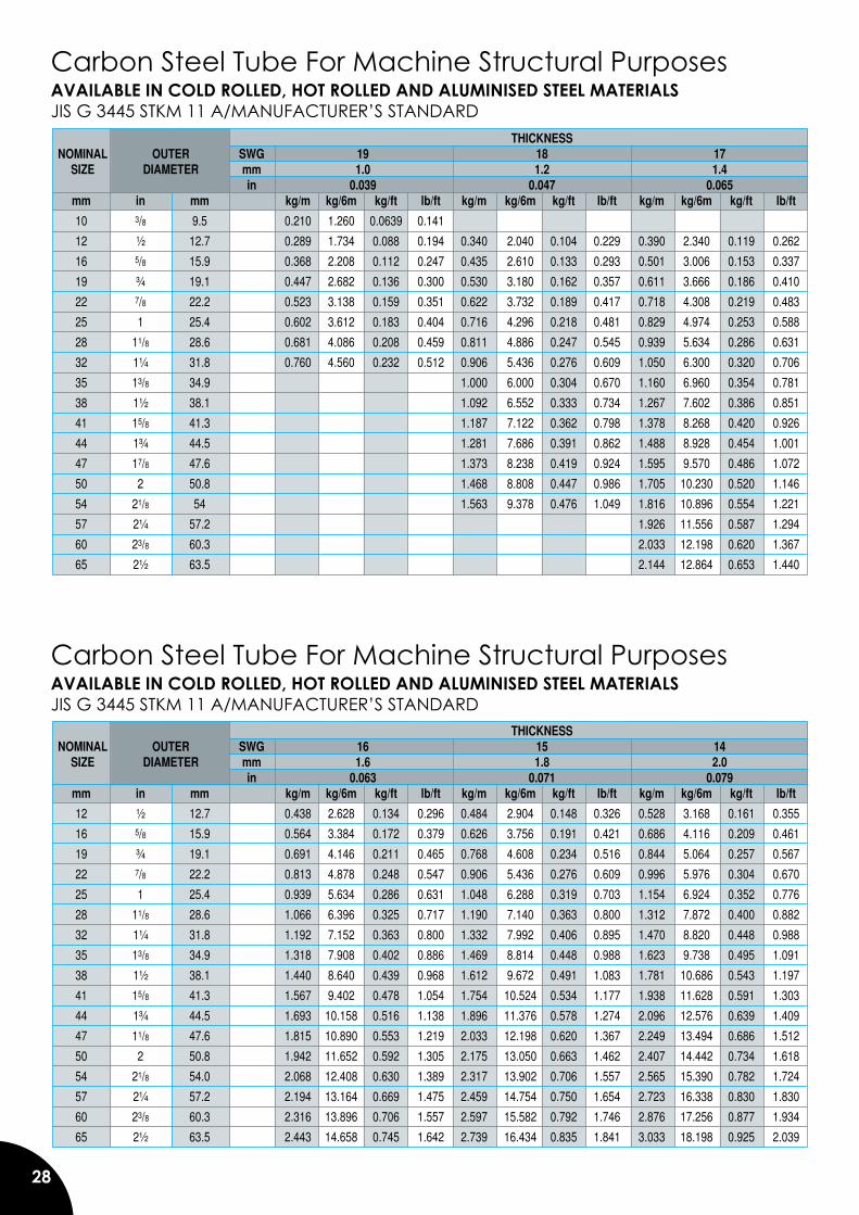
Carbon Steel Tube For Machine Structural PurposesAVAILABLE IN COLD ROLLED, HOT ROLLED AND ALUMINISED STEEL MATERIALSJIS G 3445 STKM 11 A/MANUFACTURER’S STANDARD THICKNESS NOMINAL OUTER SWG 19 18 17 SIZE DIAMETER mm 1.0 1.2 1.4 in 0.039 0.047 0.065 mm in mm kg/m kg/6m kg/ft lb/ft kg/m kg/6m kg/ft lb/ft kg/m kg/6m kg/ft lb/ft
10 3/8 9.5 0.210 1.260 0.0639 0.141
12 ½ 12.7 0.289 1.734 0.088 0.194 0.340 2.040 0.104 0.229 0.390 2.340 0.119 0.262
16 5/8 15.9 0.368 2.208 0.112 0.247 0.435 2.610 0.133 0.293 0.501 3.006 0.153 0.337
19 ¾ 19.1 0.447 2.682 0.136 0.300 0.530 3.180 0.162 0.357 0.611 3.666 0.186 0.410
22 7/8 22.2 0.523 3.138 0.159 0.351 0.622 3.732 0.189 0.417 0.718 4.308 0.219 0.483
25 1 25.4 0.602 3.612 0.183 0.404 0.716 4.296 0.218 0.481 0.829 4.974 0.253 0.588
28 11/8 28.6 0.681 4.086 0.208 0.459 0.811 4.886 0.247 0.545 0.939 5.634 0.286 0.631
32 1¼ 31.8 0.760 4.560 0.232 0.512 0.906 5.436 0.276 0.609 1.050 6.300 0.320 0.706
35 13/8 34.9 1.000 6.000 0.304 0.670 1.160 6.960 0.354 0.781
38 1½ 38.1 1.092 6.552 0.333 0.734 1.267 7.602 0.386 0.851
41 15/8 41.3 1.187 7.122 0.362 0.798 1.378 8.268 0.420 0.926
44 1¾ 44.5 1.281 7.686 0.391 0.862 1.488 8.928 0.454 1.001
47 17/8 47.6 1.373 8.238 0.419 0.924 1.595 9.570 0.486 1.072
50 2 50.8 1.468 8.808 0.447 0.986 1.705 10.230 0.520 1.146
54 21/8 54 1.563 9.378 0.476 1.049 1.816 10.896 0.554 1.221
57 2¼ 57.2 1.926 11.556 0.587 1.294
60 23/8 60.3 2.033 12.198 0.620 1.367
65 2½ 63.5 2.144 12.864 0.653 1.440
Carbon Steel Tube For Machine Structural PurposesAVAILABLE IN COLD ROLLED, HOT ROLLED AND ALUMINISED STEEL MATERIALSJIS G 3445 STKM 11 A/MANUFACTURER’S STANDARD THICKNESS NOMINAL OUTER SWG 16 15 14 SIZE DIAMETER mm 1.6 1.8 2.0 in 0.063 0.071 0.079 mm in mm kg/m kg/6m kg/ft lb/ft kg/m kg/6m kg/ft lb/ft kg/m kg/6m kg/ft lb/ft
12 ½ 12.7 0.438 2.628 0.134 0.296 0.484 2.904 0.148 0.326 0.528 3.168 0.161 0.355
16 5/8 15.9 0.564 3.384 0.172 0.379 0.626 3.756 0.191 0.421 0.686 4.116 0.209 0.461
19 ¾ 19.1 0.691 4.146 0.211 0.465 0.768 4.608 0.234 0.516 0.844 5.064 0.257 0.567
22 7/8 22.2 0.813 4.878 0.248 0.547 0.906 5.436 0.276 0.609 0.996 5.976 0.304 0.670
25 1 25.4 0.939 5.634 0.286 0.631 1.048 6.288 0.319 0.703 1.154 6.924 0.352 0.776
28 11/8 28.6 1.066 6.396 0.325 0.717 1.190 7.140 0.363 0.800 1.312 7.872 0.400 0.882
32 1¼ 31.8 1.192 7.152 0.363 0.800 1.332 7.992 0.406 0.895 1.470 8.820 0.448 0.988
35 13/8 34.9 1.318 7.908 0.402 0.886 1.469 8.814 0.448 0.988 1.623 9.738 0.495 1.091
38 1½ 38.1 1.440 8.640 0.439 0.968 1.612 9.672 0.491 1.083 1.781 10.686 0.543 1.197
41 15/8 41.3 1.567 9.402 0.478 1.054 1.754 10.524 0.534 1.177 1.938 11.628 0.591 1.303
44 1¾ 44.5 1.693 10.158 0.516 1.138 1.896 11.376 0.578 1.274 2.096 12.576 0.639 1.409
47 11/8 47.6 1.815 10.890 0.553 1.219 2.033 12.198 0.620 1.367 2.249 13.494 0.686 1.512
50 2 50.8 1.942 11.652 0.592 1.305 2.175 13.050 0.663 1.462 2.407 14.442 0.734 1.618
54 21/8 54.0 2.068 12.408 0.630 1.389 2.317 13.902 0.706 1.557 2.565 15.390 0.782 1.724
57 2¼ 57.2 2.194 13.164 0.669 1.475 2.459 14.754 0.750 1.654 2.723 16.338 0.830 1.830
60 23/8 60.3 2.316 13.896 0.706 1.557 2.597 15.582 0.792 1.746 2.876 17.256 0.877 1.934
65 2½ 63.5 2.443 14.658 0.745 1.642 2.739 16.434 0.835 1.841 3.033 18.198 0.925 2.039
29
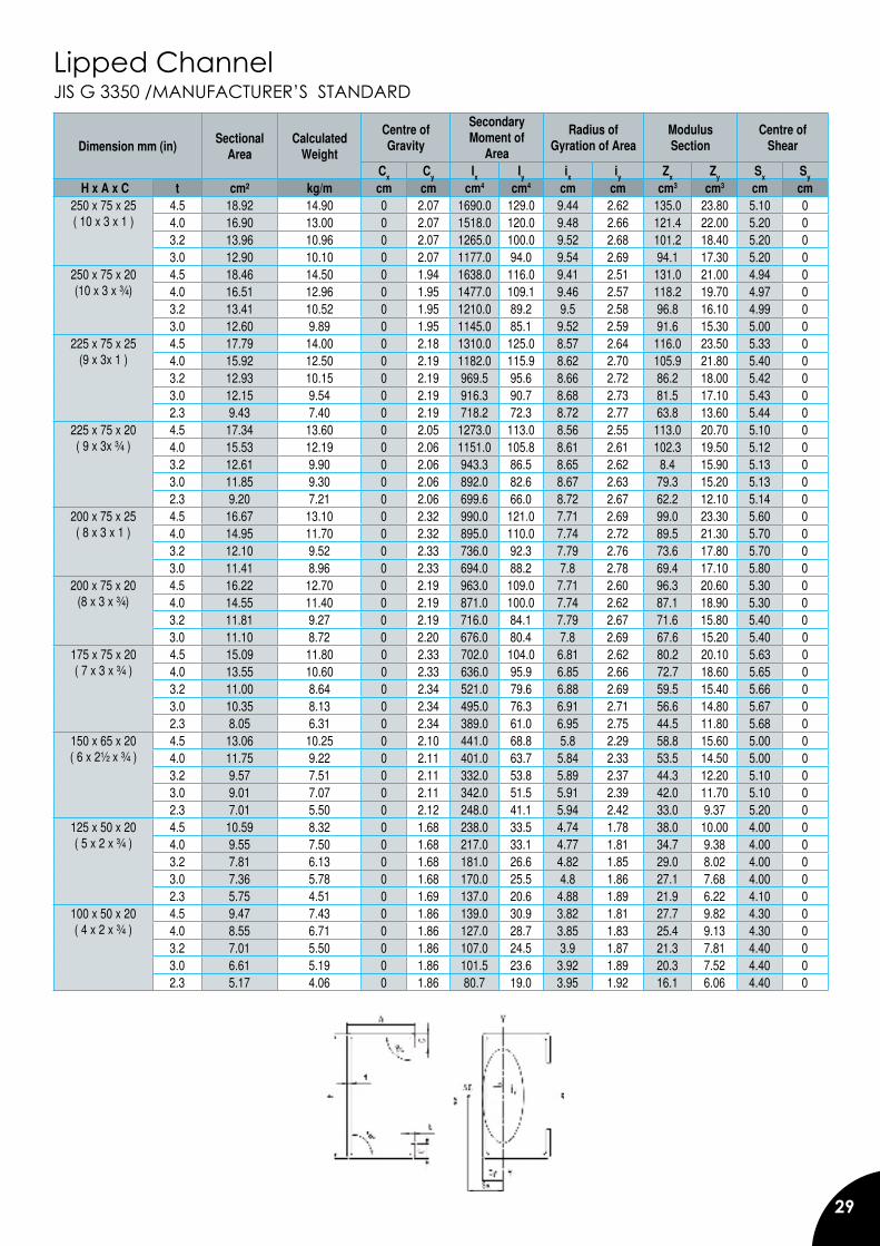
Lipped Channel JIS G 3350 /MANUFACTURER’S STANDARD
Dimension mm (in)Sectional
AreaCalculated
Weight
Centre of Gravity
Secondary Moment of
Area
Radius of Gyration of Area
Modulus Section
Centre of Shear
Cx Cy Ix Iy ix iy Zx Zy Sx Sy
H x A x C t cm² kg/m cm cm cm4 cm4 cm cm cm3 cm3 cm cm250 x 75 x 25( 10 x 3 x 1 )
4.5 18.92 14.90 0 2.07 1690.0 129.0 9.44 2.62 135.0 23.80 5.10 04.0 16.90 13.00 0 2.07 1518.0 120.0 9.48 2.66 121.4 22.00 5.20 03.2 13.96 10.96 0 2.07 1265.0 100.0 9.52 2.68 101.2 18.40 5.20 03.0 12.90 10.10 0 2.07 1177.0 94.0 9.54 2.69 94.1 17.30 5.20 0
250 x 75 x 20 (10 x 3 x ¾)
4.5 18.46 14.50 0 1.94 1638.0 116.0 9.41 2.51 131.0 21.00 4.94 04.0 16.51 12.96 0 1.95 1477.0 109.1 9.46 2.57 118.2 19.70 4.97 03.2 13.41 10.52 0 1.95 1210.0 89.2 9.5 2.58 96.8 16.10 4.99 03.0 12.60 9.89 0 1.95 1145.0 85.1 9.52 2.59 91.6 15.30 5.00 0
225 x 75 x 25(9 x 3x 1 )
4.5 17.79 14.00 0 2.18 1310.0 125.0 8.57 2.64 116.0 23.50 5.33 04.0 15.92 12.50 0 2.19 1182.0 115.9 8.62 2.70 105.9 21.80 5.40 03.2 12.93 10.15 0 2.19 969.5 95.6 8.66 2.72 86.2 18.00 5.42 03.0 12.15 9.54 0 2.19 916.3 90.7 8.68 2.73 81.5 17.10 5.43 02.3 9.43 7.40 0 2.19 718.2 72.3 8.72 2.77 63.8 13.60 5.44 0
225 x 75 x 20 ( 9 x 3x ¾ )
4.5 17.34 13.60 0 2.05 1273.0 113.0 8.56 2.55 113.0 20.70 5.10 04.0 15.53 12.19 0 2.06 1151.0 105.8 8.61 2.61 102.3 19.50 5.12 03.2 12.61 9.90 0 2.06 943.3 86.5 8.65 2.62 8.4 15.90 5.13 03.0 11.85 9.30 0 2.06 892.0 82.6 8.67 2.63 79.3 15.20 5.13 02.3 9.20 7.21 0 2.06 699.6 66.0 8.72 2.67 62.2 12.10 5.14 0
200 x 75 x 25( 8 x 3 x 1 )
4.5 16.67 13.10 0 2.32 990.0 121.0 7.71 2.69 99.0 23.30 5.60 04.0 14.95 11.70 0 2.32 895.0 110.0 7.74 2.72 89.5 21.30 5.70 03.2 12.10 9.52 0 2.33 736.0 92.3 7.79 2.76 73.6 17.80 5.70 03.0 11.41 8.96 0 2.33 694.0 88.2 7.8 2.78 69.4 17.10 5.80 0
200 x 75 x 20(8 x 3 x ¾)
4.5 16.22 12.70 0 2.19 963.0 109.0 7.71 2.60 96.3 20.60 5.30 04.0 14.55 11.40 0 2.19 871.0 100.0 7.74 2.62 87.1 18.90 5.30 03.2 11.81 9.27 0 2.19 716.0 84.1 7.79 2.67 71.6 15.80 5.40 03.0 11.10 8.72 0 2.20 676.0 80.4 7.8 2.69 67.6 15.20 5.40 0
175 x 75 x 20 ( 7 x 3 x ¾ )
4.5 15.09 11.80 0 2.33 702.0 104.0 6.81 2.62 80.2 20.10 5.63 04.0 13.55 10.60 0 2.33 636.0 95.9 6.85 2.66 72.7 18.60 5.65 03.2 11.00 8.64 0 2.34 521.0 79.6 6.88 2.69 59.5 15.40 5.66 03.0 10.35 8.13 0 2.34 495.0 76.3 6.91 2.71 56.6 14.80 5.67 02.3 8.05 6.31 0 2.34 389.0 61.0 6.95 2.75 44.5 11.80 5.68 0
150 x 65 x 20 ( 6 x 2½ x ¾ )
4.5 13.06 10.25 0 2.10 441.0 68.8 5.8 2.29 58.8 15.60 5.00 04.0 11.75 9.22 0 2.11 401.0 63.7 5.84 2.33 53.5 14.50 5.00 03.2 9.57 7.51 0 2.11 332.0 53.8 5.89 2.37 44.3 12.20 5.10 03.0 9.01 7.07 0 2.11 342.0 51.5 5.91 2.39 42.0 11.70 5.10 02.3 7.01 5.50 0 2.12 248.0 41.1 5.94 2.42 33.0 9.37 5.20 0
125 x 50 x 20( 5 x 2 x ¾ )
4.5 10.59 8.32 0 1.68 238.0 33.5 4.74 1.78 38.0 10.00 4.00 04.0 9.55 7.50 0 1.68 217.0 33.1 4.77 1.81 34.7 9.38 4.00 03.2 7.81 6.13 0 1.68 181.0 26.6 4.82 1.85 29.0 8.02 4.00 03.0 7.36 5.78 0 1.68 170.0 25.5 4.8 1.86 27.1 7.68 4.00 02.3 5.75 4.51 0 1.69 137.0 20.6 4.88 1.89 21.9 6.22 4.10 0
100 x 50 x 20( 4 x 2 x ¾ )
4.5 9.47 7.43 0 1.86 139.0 30.9 3.82 1.81 27.7 9.82 4.30 04.0 8.55 6.71 0 1.86 127.0 28.7 3.85 1.83 25.4 9.13 4.30 03.2 7.01 5.50 0 1.86 107.0 24.5 3.9 1.87 21.3 7.81 4.40 03.0 6.61 5.19 0 1.86 101.5 23.6 3.92 1.89 20.3 7.52 4.40 02.3 5.17 4.06 0 1.86 80.7 19.0 3.95 1.92 16.1 6.06 4.40 0
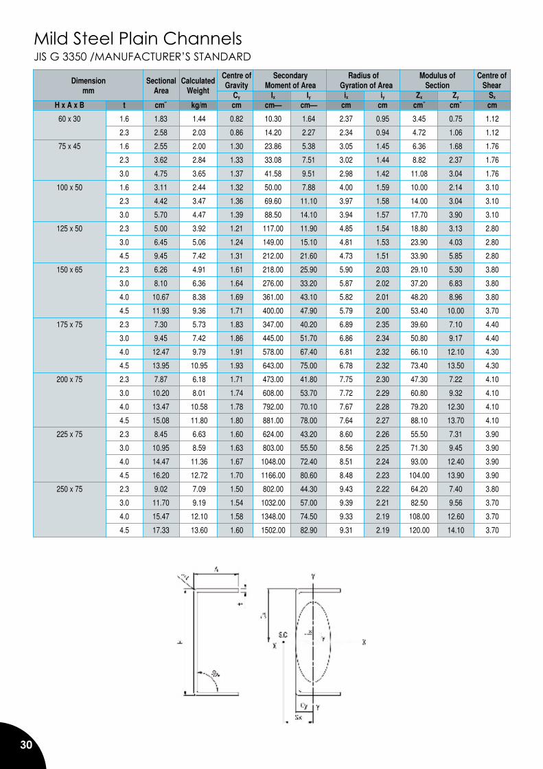
30
Mild Steel Plain ChannelsJIS G 3350 /MANUFACTURER’S STANDARD Centre of Secondary Radius of Modulus of Gravity Moment of Area Gyration of Area Section Cy Ix Iy ix iy Zx Zy Sx
H x A x B t cm� kg/m cm cm� cm� cm cm cm� cm� cm
60 x 30 1.6 1.83 1.44 0.82 10.30 1.64 2.37 0.95 3.45 0.75 1.12
2.3 2.58 2.03 0.86 14.20 2.27 2.34 0.94 4.72 1.06 1.12
75 x 45 1.6 2.55 2.00 1.30 23.86 5.38 3.05 1.45 6.36 1.68 1.76
2.3 3.62 2.84 1.33 33.08 7.51 3.02 1.44 8.82 2.37 1.76
3.0 4.75 3.65 1.37 41.58 9.51 2.98 1.42 11.08 3.04 1.76
100 x 50 1.6 3.11 2.44 1.32 50.00 7.88 4.00 1.59 10.00 2.14 3.10
2.3 4.42 3.47 1.36 69.60 11.10 3.97 1.58 14.00 3.04 3.10
3.0 5.70 4.47 1.39 88.50 14.10 3.94 1.57 17.70 3.90 3.10
125 x 50 2.3 5.00 3.92 1.21 117.00 11.90 4.85 1.54 18.80 3.13 2.80
3.0 6.45 5.06 1.24 149.00 15.10 4.81 1.53 23.90 4.03 2.80
4.5 9.45 7.42 1.31 212.00 21.60 4.73 1.51 33.90 5.85 2.80
150 x 65 2.3 6.26 4.91 1.61 218.00 25.90 5.90 2.03 29.10 5.30 3.80
3.0 8.10 6.36 1.64 276.00 33.20 5.87 2.02 37.20 6.83 3.80
4.0 10.67 8.38 1.69 361.00 43.10 5.82 2.01 48.20 8.96 3.80
4.5 11.93 9.36 1.71 400.00 47.90 5.79 2.00 53.40 10.00 3.70
175 x 75 2.3 7.30 5.73 1.83 347.00 40.20 6.89 2.35 39.60 7.10 4.40
3.0 9.45 7.42 1.86 445.00 51.70 6.86 2.34 50.80 9.17 4.40
4.0 12.47 9.79 1.91 578.00 67.40 6.81 2.32 66.10 12.10 4.30
4.5 13.95 10.95 1.93 643.00 75.00 6.78 2.32 73.40 13.50 4.30
200 x 75 2.3 7.87 6.18 1.71 473.00 41.80 7.75 2.30 47.30 7.22 4.10
3.0 10.20 8.01 1.74 608.00 53.70 7.72 2.29 60.80 9.32 4.10
4.0 13.47 10.58 1.78 792.00 70.10 7.67 2.28 79.20 12.30 4.10
4.5 15.08 11.80 1.80 881.00 78.00 7.64 2.27 88.10 13.70 4.10
225 x 75 2.3 8.45 6.63 1.60 624.00 43.20 8.60 2.26 55.50 7.31 3.90
3.0 10.95 8.59 1.63 803.00 55.50 8.56 2.25 71.30 9.45 3.90
4.0 14.47 11.36 1.67 1048.00 72.40 8.51 2.24 93.00 12.40 3.90
4.5 16.20 12.72 1.70 1166.00 80.60 8.48 2.23 104.00 13.90 3.90
250 x 75 2.3 9.02 7.09 1.50 802.00 44.30 9.43 2.22 64.20 7.40 3.80
3.0 11.70 9.19 1.54 1032.00 57.00 9.39 2.21 82.50 9.56 3.70
4.0 15.47 12.10 1.58 1348.00 74.50 9.33 2.19 108.00 12.60 3.70
4.5 17.33 13.60 1.60 1502.00 82.90 9.31 2.19 120.00 14.10 3.70
Dimensionmm
SectionalArea
Centre ofShearCalculated
Weight
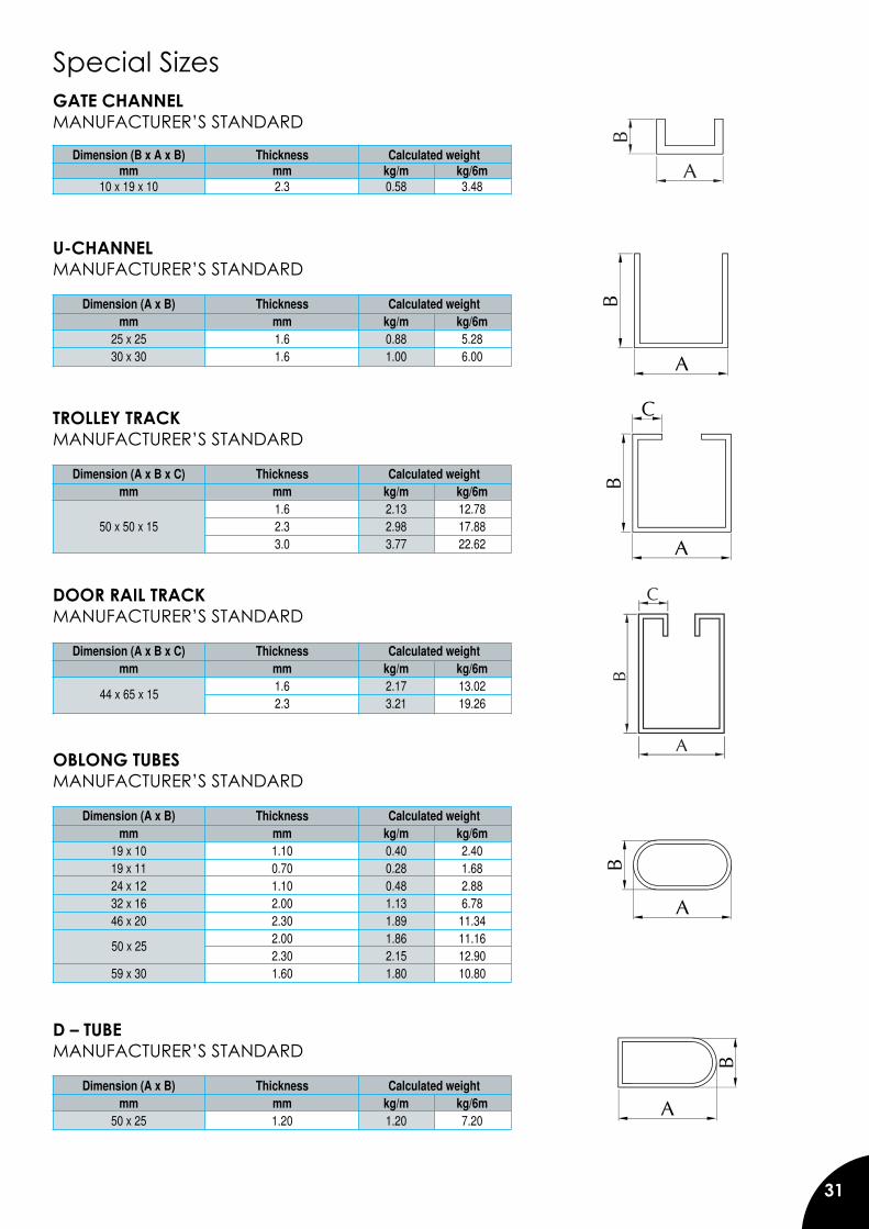
31
Special SizesGATE CHANNEL MANUFACTURER’S STANDARD
Dimension (B x A x B) Thickness Calculated weight mm mm kg/m kg/6m 10 x 19 x 10 2.3 0.58 3.48
U-CHANNELMANUFACTURER’S STANDARD
Dimension (A x B) Thickness Calculated weight mm mm kg/m kg/6m 25 x 25 1.6 0.88 5.28 30 x 30 1.6 1.00 6.00
TROLLEY TRACKMANUFACTURER’S STANDARD
Dimension (A x B x C) Thickness Calculated weight mm mm kg/m kg/6m 1.6 2.13 12.78 50 x 50 x 15 2.3 2.98 17.88 3.0 3.77 22.62
DOOR RAIL TRACKMANUFACTURER’S STANDARD
Dimension (A x B x C) Thickness Calculated weight mm mm kg/m kg/6m 1.6 2.17 13.02 2.3 3.21 19.26
OBLONG TUBESMANUFACTURER’S STANDARD
Dimension (A x B) Thickness Calculated weight mm mm kg/m kg/6m 19 x 10 1.10 0.40 2.40 19 x 11 0.70 0.28 1.68 24 x 12 1.10 0.48 2.88 32 x 16 2.00 1.13 6.78 46 x 20 2.30 1.89 11.34 2.00 1.86 11.16 2.30 2.15 12.90 59 x 30 1.60 1.80 10.80
D – TUBEMANUFACTURER’S STANDARD
Dimension (A x B) Thickness Calculated weight mm mm kg/m kg/6m 50 x 25 1.20 1.20 7.20
44 x 65 x 15
50 x 25
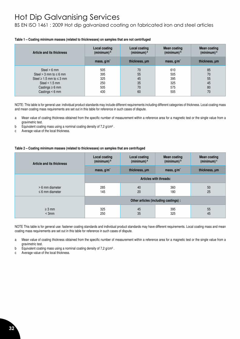
32
Hot Dip Galvanising ServicesBS EN ISO 1461 : 2009 Hot dip galvanized coating on fabricated iron and steel articles
Table 1 – Coating minimum masses (related to thicknesses) on samples that are not centrifuged Local coating Local coating Mean coating Mean coating Article and its thickness (minimum) b (minimum) a (minimum) b (minimum) a mass, g/m� thickness, µm mass, g/m� thickness, µm Steel > 6 mm 505 70 610 85 Steel > 3 mm to ≤ 6 mm 395 55 505 70 Steel ≥ 1.5 mm to ≤ 3 mm 325 45 395 55 Steel < 1.5 mm 250 35 325 45 Castings ≥ 6 mm 505 70 575 80 Castings < 6 mm 430 60 505 70 NOTE: This table is for general use: individual product standards may include different requirements including different categories of thickness. Local coating mass and mean coating mass requirements are set out in this table for reference in such cases of dispute. a Mean value of coating thickness obtained from the specific number of measurement within a reference area for a magnetic test or the single value from a
gravimetric test. b Equivalent coating mass using a nominal coating density of 7,2 g/cm³ . c Average value of the local thickness.
Table 2 – Coating minimum masses (related to thicknesses) on samples that are centrifuged Local coating Local coating Mean coating Mean coating (minimum) b (minimum) a (minimum) b (minimum) c mass, g/m� thickness, µm mass, g/m� thickness, µm
Articles with threads:
> 6 mm diameter 285 40 360 50 ≤ 6 mm diameter 145 20 180 25 Other articles (including castings) : ≥ 3 mm 325 45 395 55 < 3mm 250 35 325 45 NOTE This table is for general use: fastener coating standards and individual product standards may have different requirements. Local coating mass and mean coating mass requirements are set out in this table for reference in such cases of dispute. a Mean value of coating thickness obtained from the specific number of measurement within a reference area for a magnetic test or the single value from a
gravimetric test. b Equivalent coating mass using a nominal coating density of 7,2 g/cm³ . c Average value of the local thickness.
Article and its thickness
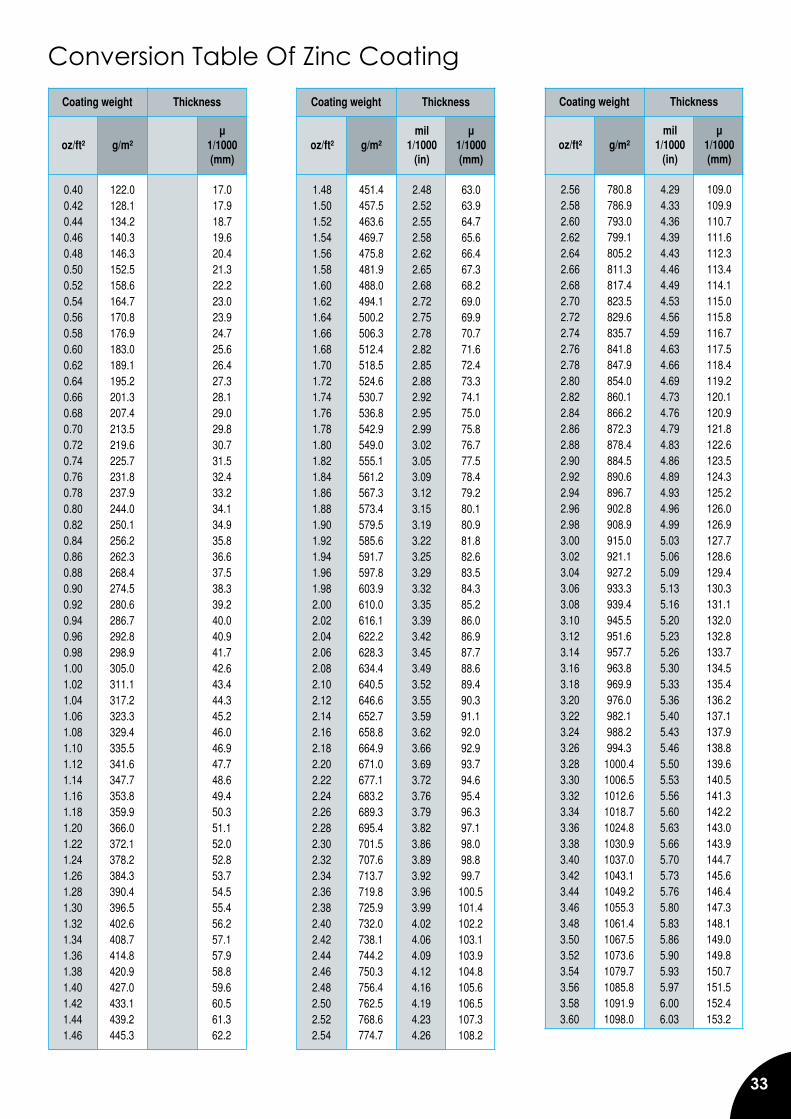
33
Conversion Table Of Zinc Coating Coating weight Thickness
mil µ oz/ft² g/m² 1/1000 1/1000 (in) (mm)
0.40 122.0 0.67 17.0 0.42 128.1 0.70 17.9 0.44 134.2 0.74 18.7 0.46 140.3 0.77 19.6 0.48 146.3 0.81 20.4 0.50 152.5 0.84 21.3 0.52 158.6 0.87 22.2 0.54 164.7 0.91 23.0 0.56 170.8 0.94 23.9 0.58 176.9 0.97 24.7 0.60 183.0 1.01 25.6 0.62 189.1 1.04 26.4 0.64 195.2 1.07 27.3 0.66 201.3 1.11 28.1 0.68 207.4 1.14 29.0 0.70 213.5 1.17 29.8 0.72 219.6 1.21 30.7 0.74 225.7 1.24 31.5 0.76 231.8 1.27 32.4 0.78 237.9 1.31 33.2 0.80 244.0 1.34 34.1 0.82 250.1 1.38 34.9 0.84 256.2 1.41 35.8 0.86 262.3 1.44 36.6 0.88 268.4 1.48 37.5 0.90 274.5 1.51 38.3 0.92 280.6 1.54 39.2 0.94 286.7 1.58 40.0 0.96 292.8 1.61 40.9 0.98 298.9 1.64 41.7 1.00 305.0 1.68 42.6 1.02 311.1 1.71 43.4 1.04 317.2 1.74 44.3 1.06 323.3 1.78 45.2 1.08 329.4 1.81 46.0 1.10 335.5 1.84 46.9 1.12 341.6 1.88 47.7 1.14 347.7 1.91 48.6 1.16 353.8 1.95 49.4 1.18 359.9 1.98 50.3 1.20 366.0 2.01 51.1 1.22 372.1 2.05 52.0 1.24 378.2 2.08 52.8 1.26 384.3 2.11 53.7 1.28 390.4 2.15 54.5 1.30 396.5 2.18 55.4 1.32 402.6 2.21 56.2 1.34 408.7 2.25 57.1 1.36 414.8 2.28 57.9 1.38 420.9 2.31 58.8 1.40 427.0 2.35 59.6 1.42 433.1 2.38 60.5 1.44 439.2 2.41 61.3 1.46 445.3 2.45 62.2
Coating weight Thickness
mil µ oz/ft² g/m² 1/1000 1/1000 (in) (mm)
1.48 451.4 2.48 63.0 1.50 457.5 2.52 63.9 1.52 463.6 2.55 64.7 1.54 469.7 2.58 65.6 1.56 475.8 2.62 66.4 1.58 481.9 2.65 67.3 1.60 488.0 2.68 68.2 1.62 494.1 2.72 69.0 1.64 500.2 2.75 69.9 1.66 506.3 2.78 70.7 1.68 512.4 2.82 71.6 1.70 518.5 2.85 72.4 1.72 524.6 2.88 73.3 1.74 530.7 2.92 74.1 1.76 536.8 2.95 75.0 1.78 542.9 2.99 75.8 1.80 549.0 3.02 76.7 1.82 555.1 3.05 77.5 1.84 561.2 3.09 78.4 1.86 567.3 3.12 79.2 1.88 573.4 3.15 80.1 1.90 579.5 3.19 80.9 1.92 585.6 3.22 81.8 1.94 591.7 3.25 82.6 1.96 597.8 3.29 83.5 1.98 603.9 3.32 84.3 2.00 610.0 3.35 85.2 2.02 616.1 3.39 86.0 2.04 622.2 3.42 86.9 2.06 628.3 3.45 87.7 2.08 634.4 3.49 88.6 2.10 640.5 3.52 89.4 2.12 646.6 3.55 90.3 2.14 652.7 3.59 91.1 2.16 658.8 3.62 92.0 2.18 664.9 3.66 92.9 2.20 671.0 3.69 93.7 2.22 677.1 3.72 94.6 2.24 683.2 3.76 95.4 2.26 689.3 3.79 96.3 2.28 695.4 3.82 97.1 2.30 701.5 3.86 98.0 2.32 707.6 3.89 98.8 2.34 713.7 3.92 99.7 2.36 719.8 3.96 100.5 2.38 725.9 3.99 101.4 2.40 732.0 4.02 102.2 2.42 738.1 4.06 103.1 2.44 744.2 4.09 103.9 2.46 750.3 4.12 104.8 2.48 756.4 4.16 105.6 2.50 762.5 4.19 106.5 2.52 768.6 4.23 107.3 2.54 774.7 4.26 108.2
Coating weight Thickness
mil µ oz/ft² g/m² 1/1000 1/1000 (in) (mm)
2.56 780.8 4.29 109.0 2.58 786.9 4.33 109.9 2.60 793.0 4.36 110.7 2.62 799.1 4.39 111.6 2.64 805.2 4.43 112.3 2.66 811.3 4.46 113.4 2.68 817.4 4.49 114.1 2.70 823.5 4.53 115.0 2.72 829.6 4.56 115.8 2.74 835.7 4.59 116.7 2.76 841.8 4.63 117.5 2.78 847.9 4.66 118.4 2.80 854.0 4.69 119.2 2.82 860.1 4.73 120.1 2.84 866.2 4.76 120.9 2.86 872.3 4.79 121.8 2.88 878.4 4.83 122.6 2.90 884.5 4.86 123.5 2.92 890.6 4.89 124.3 2.94 896.7 4.93 125.2 2.96 902.8 4.96 126.0 2.98 908.9 4.99 126.9 3.00 915.0 5.03 127.7 3.02 921.1 5.06 128.6 3.04 927.2 5.09 129.4 3.06 933.3 5.13 130.3 3.08 939.4 5.16 131.1 3.10 945.5 5.20 132.0 3.12 951.6 5.23 132.8 3.14 957.7 5.26 133.7 3.16 963.8 5.30 134.5 3.18 969.9 5.33 135.4 3.20 976.0 5.36 136.2 3.22 982.1 5.40 137.1 3.24 988.2 5.43 137.9 3.26 994.3 5.46 138.8 3.28 1000.4 5.50 139.6 3.30 1006.5 5.53 140.5 3.32 1012.6 5.56 141.3 3.34 1018.7 5.60 142.2 3.36 1024.8 5.63 143.0 3.38 1030.9 5.66 143.9 3.40 1037.0 5.70 144.7 3.42 1043.1 5.73 145.6 3.44 1049.2 5.76 146.4 3.46 1055.3 5.80 147.3 3.48 1061.4 5.83 148.1 3.50 1067.5 5.86 149.0 3.52 1073.6 5.90 149.8 3.54 1079.7 5.93 150.7 3.56 1085.8 5.97 151.5 3.58 1091.9 6.00 152.4 3.60 1098.0 6.03 153.2
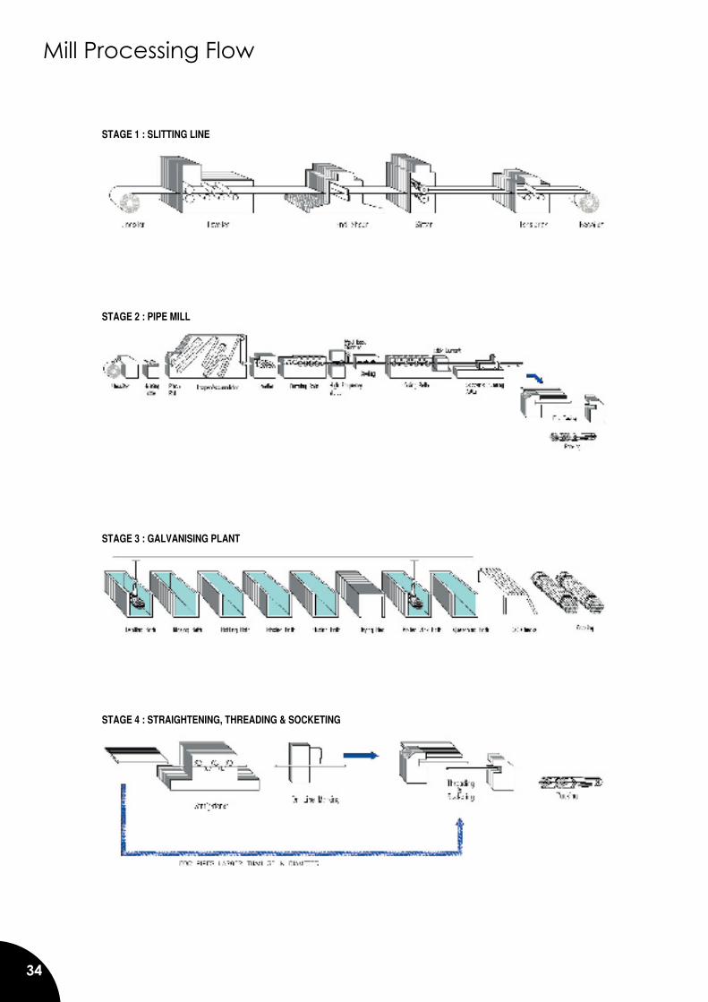
34
Mill Processing Flow
STAGE 1 : SLITTING LINE
STAGE 2 : PIPE MILL
STAGE 3 : GALVANISING PLANT
STAGE 4 : STRAIGHTENING, THREADING & SOCKETING

35
ROUND PIPES SQUARE HOLLOWSECTIONS
SQUARE HOLLOWSECTIONS
RECTANGULAR HOLLOW SECTIONS
RECTANGULAR HOLLOW SECTIONSBLACK WELDED PIPES
GALVANISED PIPESSQUARE HOLLOW SECTIONS
ROUND PIPES ROUND PIPES
Products Supplied forKuala Lumpur International Airport Project
Products Supplied forPetronas Twin Towers Project