Embed Size (px)
Citation preview

Cover NEXT-GEN.1-ang: Cover NEXT-GEN.1AN 5/7/07 11:41 AM Page 3
Acknowledgements
This guide would not have been possible without the valuable input and teamwork of the EXFO team; particularly Mr. Claudio Mazzuca,B.Eng., M.B.A, Senior Product Manager; Ms. Mai Abou-Shaban, B.Eng, Application Engineer; Mr. Robert Gendron, B.Eng, Systems Engineer; and Mr. Luc Germain, B.Eng, Systems/Architecture Manager.
No part of this guide may be reproduced in any form or by any means without the prior written permission of EXFO.
Printed and bound in Canada
ISBN 1-55342-005-5
Legal Deposit—National Library of Canada 2004Legal Deposit—National Library of Quebec 2004
© 2005 EXFO Electro-Optical Engineering Inc., Quebec City, Canada. All Rights Reserved.Next-Generation SONET/SDH Reference Guide
Cover NEXT-GEN.1-ang: Cover NEXT-GEN.1AN 5/7/07 11:41 AM Page 5

Unit price: US$19.95
For details on any of our products and services,or to download technical and application notes,visit our website at www.exfo.com.
SNO
TE/S
DH.1
AN 0
4/06
Cover NEXT-GEN.1-ang: Cover NEXT-GEN.1AN 5/7/07 11:41 AM Page 2

www.exfo.com
EXFO is a recognized test and measurement expert in the global telecommunications industry through the design and manufacture ofadvanced and innovative solutions as well as best-in-class customer support. The Telecom Division, which represents the company’s mainbusiness activity, offers fully integrated and complete test solutions to network service providers, system vendors and componentmanufacturers in approximately 70 countries. One of EXFO’s strongest competitive advantages is its PC/Windows-based modularplatforms that host a wide range of tests across optical, physical, data and network layers, while maximizing technology reuse acrossseveral market segments. The Photonics and Life Sciences Division mainly leverages core telecom technologies to offer value-addedsolutions in the life sciences and high-precision assembly sectors. For more information about EXFO, visit www.exfo.com.
About EXFO
Cover NEXT-GEN.1-ang: Cover NEXT-GEN.1AN 5/7/07 11:41 AM Page 4

Next-Generation SONET/SDH Guide EXFO 1www.exfo.com
Table of Contents1. Introduction..........................................................................................................3
2. SONET/SDH Basics ........................................................................................52.1 Transport Rates ....................................................................................................52.2 Multiplexing Scheme ..........................................................................................62.3 Network Hierarchy ..............................................................................................92.4 Basic Frame ........................................................................................................12
2.4.1 SONET STS-1 Frame Format ............................................................122.4.2 STM-1 Frame Format ............................................................................18
2.5 Virtual Tributaries/Containers..........................................................................232.5.1 SONET Virtual Tributaries ....................................................................242.5.2 SDH Virtual Tributaries..........................................................................25
3. Why Next-Generation SONET/SDH? ......................................................28
4. Generic Framing Procedure (GFP) ..........................................................314.1 GFP Mapping ....................................................................................................324.2 GFP Frame Structure ......................................................................................344.3 GFP Summary....................................................................................................40
5. Virtual Concatenation (VCAT) ....................................................................425.1 High-Order VCAT ............................................................................................45
5.1.1 High-Order VCAT Frame Structure ....................................................455.1.2 High-Order VCAT Multiframe Indicator..............................................475.1.3 High-Order Path Sequence Indicator................................................48
5.2 Low-Order VCAT ..............................................................................................495.2.1 Low-Order VCAT Frame Structure ....................................................495.2.2 Low-Order VCAT Multiframe and Sequence Indicator ..................51
5.3 VCAT Differential Delay ....................................................................................525.4 VCAT Summary ..................................................................................................53
6. Link-Capacity Adjustment Scheme (LCAS) ..........................................556.1 LCAS Control Packets......................................................................................576.2 LCAS Example 1: Capacity Increase............................................................586.3 LCAS Example 2: Capacity Reduction ........................................................61
7. Next-Generation SONET/SDH: Testing Implications ........................667.1 GFP Test Scenarios..........................................................................................667.2 VCAT Test Scenarios ........................................................................................697.3 LCAS Test Scenarios ........................................................................................727.4 Continuity and Performance Testing ............................................................747.5 Service Turn-Up Testing....................................................................................747.6 Network Troubleshooting ................................................................................78
8. Conclusion ........................................................................................................81
9. Next-Generation Alarms Index ..................................................................83
10.Acronyms Index ..............................................................................................87
11. References ........................................................................................................90
Acknowledgements ..............................................................................................93
Guide NEXT-GEN.3-ang: Guide Ethernet.1AN 5/7/07 11:31 AM Page 1

Introduction
Guide NEXT-GEN.3-ang: Guide Ethernet.1AN 5/7/07 11:31 AM Page 2

Next-Generation SONET/SDH Guide EXFO 3www.exfo.com
1. Introduction to SONET/SDH TechnologySONET/SDH networks have stood the test of time and, until recently, they have been primarily used to transport aggregated voice signals andprivate-line frame-relay and ATM services. The growth of these high-revenue-generating services over the years has resulted in large-scaledeployments of metropolitan and long-haul SONET/SDH networks worldwide.
Today, however, service demand and, consequently, service-provider revenue growth has shifted from these legacy-based services to IP/Ethernet-based services. This shift in demand is largely due to two market factors. First, enterprise customers have expressed an increasingneed for reliable Ethernet-based transport services and, second, Ethernet is becoming the Layer 2 transport technology of choice for bothenterprise connectivity and access aggregation networks. In addition, with the convergence of voice, video and data (e.g., triple-play accessnetworks), Ethernet connections are now being used for delivery of mission-critical services, thus making 99.999% reliability an absolute servicerequirement for these enterprise customers.
This growing demand for Ethernet-based transport services has led to a “rebirth” of SONET/SDH. Given the fundamental robustness of thetechnology and the massive capital investment that has been made over the years, service providers have been eager to find ways of using theirexisting SONET/SDH infrastructure to fulfill the growing market demand for Ethernet.
Packet-aware SONET/SDH add-drop multiplexers, commonly known as multiservice provisioning platforms (MSPPs), are actively being deployedin service-provider networks worldwide, as they offer an efficient means of transporting packet-based client signals, such as Ethernet and FibreChannel, over existing SONET/SDH infrastructures. This efficiency is provided through their support of recent ITU and ANSI standards; namely,generic framing procedure (GFP), virtual concatenation (VCAT), and link-capacity adjustment scheme (LCAS).
This pocket guide begins by providing a refresher on SONET/SDH and then presents an in-depth look into these newly introduced next-generation SONET/SDH technologies, outlining their applications and the test scenarios that equipment vendors and service providers mustconsider when qualifying MSPPs and when activating and maintaining Ethernet-over-SONET/SDH circuits, as well as other network elements.
Guide NEXT-GEN.3-ang: Guide Ethernet.1AN 5/7/07 11:31 AM Page 3

SONET/SDH Basics
Guide NEXT-GEN.3-ang: Guide Ethernet.1AN 5/7/07 11:31 AM Page 4

Next-Generation SONET/SDH Guide EXFO 5www.exfo.com
2. SONET/SDH BasicsSynchronous Optical NETworking — commonly known as SONET — and Synchronous Digital Hierarchy (SDH) have been around for decades.Although well understood within the telecommunications industry, when discussing next-generation SONET/SDH technologies, it is important toprovide a quick refresher of the basic workings of SONET/SDH.
SONET and SDH standards were developed for communicating digital information over optical fiber. The SONET specifications define optical-carrier (OC) interfaces and their electrical equivalents to allow for transmission of lower-rate signals at a common synchronous rate. Thesespecifications were developed to replace the lower-rate T-Carrier/PDH systems, as they allow for the transport of large amounts of telephony and data traffic.
Both SONET and SDH are widely used today; SONET mainly in North America, and SDH in the rest of the world.
One of the benefits of the SONET/SDH signal, as with any standard, is that it facilitates the interoperability between multiple vendors within thesame network. Another major advantage of SONET/SDH is that the operations, administration, maintenance, and provisioning (OAM&P)capabilities are built directly into the signal overhead to allow for maintenance of the network from one central location.
2.1 Transport RatesThe following table outlines common SONET/SDH data rates supported in the standard.
Optical Level Electrical Level Line Rate (Mb/s) Payload Rate (Mb/s) SDH Equivalent
OC-1 STS-1 51.840 48.38 STM-0OC-3 STS-3 155.520 149.76 STM-1 OC-12 STS-12 622.080 599.04 STM-4 OC-48 STS-48 2488.320 2,396.16 STM-16OC-192 STS-192 9953.280 9,584.64 STM-64
Table 2.1 – Common SONET/SDH Data Rates
Guide NEXT-GEN.3-ang: Guide Ethernet.1AN 5/7/07 11:31 AM Page 5

6 Next-Generation SONET/SDH Guide EXFO www.exfo.com
2.2 Multiplexing Scheme
SONET/SDH signals can carry large payloads (above 50 Mb/s). However, the existing digital hierarchy signals can be accommodated as well,thus protecting network investments. To achieve this capability in SONET, the STS synchronous payload envelope can be subdivided into smallercomponents or structures, known as virtual tributaries (VTs), for the purpose of transporting and switching payloads smaller than the STS-1 rate.All services below the DS3 rate are transported in the VT structure. The following four multiplexing principles are used in both SONET and SDH:
• Mapping – This process takes place when tributaries are integrated into virtual tributaries (VTs) in SONET, or into virtual containers (VCs) inSDH, by adding justification bits and path overhead (POH) information.
• Aligning – This process takes place when a pointer is included in the STS path or VT path overhead to allow the first byte of the virtual tributaryto be located. Similarly, aligning is used in SDH when a pointer is included in a tributary unit (TU) or an administrative unit (AU).
• Multiplexing – This process is used when multiple lower-order path-layer signals are integrated into a higher-order path signal, or when thehigher-order path signals are integrated into the line overhead (in SONET) or into the multiplex section (in SDH).
• Stuffing – SONET and SDH both have the ability to handle various input tributary rates from asynchronous signals or PDH. As the tributary signals are multiplexed and aligned, some spare capacity has been designed into the SONET or SDH frame to provide enough space for allthese tributary rates.
Guide NEXT-GEN.3-ang: Guide Ethernet.1AN 5/7/07 11:31 AM Page 6

Next-Generation SONET/SDH Guide EXFO 7www.exfo.com
Figure 2.1 illustrates the basicmultiplexing structure of SONET. Any type of service can be acceptedby various types of service adaptersand transported over a network. All inputs, except for concatenatedsignals, are converted to a baseformat of an STS-1 signal. Lower-speed inputs such as DS1s are firstmultiplexed into virtual tributaries andthen into an STS-N (N = 1 or more)signal format.
STS-12c
STS-9c
STS-6c
STS-3c
STS-1
STS-3c
STS-1c
STS-48c
STS-24c
STS-3
VT-6 VT6VT Group
VT -2 VT2 E1
VT -1.5 VT1.5 DS1
OC-48
OC-12
Pattern
STS-192cOC-192 Pattern
Pattern
Pattern
Pattern
Pattern
Pattern
Pattern
Pattern
Pattern
Pattern
STS-1
E4
D S3/E3
x1
x1
x1
x3
x4
x7
Figure 2.1 SONET Multiplexing Hierarchy
Guide NEXT-GEN.3-ang: Guide Ethernet.1AN 5/7/07 11:31 AM Page 7

Figure 2.2 SDH Multiplexing Hierarchy
8 Next-Generation SONET/SDH Guide EXFO www.exfo.com
Figure 2.2 illustrates the SDH multiplexing scheme. Low-rate signals are input into virtual containers (VC) to create a uniform VC payload. Next, VCs are aligned into tributary units (TUs), and then the payload is multiplexed into TU groups (TUGs). The next step is multiplexing the TUGsto higher-rate VCs and then the VCs into administrative units (AUs). The AUs are finally multiplexed into the AU group (AUG), and the payload ismultiplexed into the synchronous transport module (STM).
STM-16
STM-4
STM-1e/STM-1
STM-0
AU-4-4c
AU-4-3c
AU-4-16c
AU-4-8c
AU-4-2c
AU-4AUG
VC-4-4c
VC-4-3c
VC-4-16c
VC-4-8c
VC-4-2c
VC-4
C4-4c
C4-3c
C4-16c
C4-8c
C-4-2c
C-4
AU-3 VC-3 C-3TU-3TUG 3 VC-3
TU-2TUG 2 VC-2
TU-12 VC-12
TU-11 VC-11
C-2
C-12
C-11
DS3/E3
E1
DS1
Pattern
STM-64 AU-4-64c VC-4-64c C4-64c Pattern
Pattern
Pattern
Pattern
Pattern
Pattern
PatternPattern
Pattern
PatternPattern
PatternPattern
E4Pattern
x1
x3 x3 x1
x1
x3
x4
x7x7
Guide NEXT-GEN.3-ang: Guide Ethernet.1AN 5/7/07 11:31 AM Page 8

Next-Generation SONET/SDH Guide EXFO 9www.exfo.com
2.3 Network Hierarchy
SONET and SDH are like other layered protocols in the sense that their layers communicate with other similar-type layers. SONET sections andSDH regenerator sections (RS) are defined as links between any two SONET network elements. A SONET line or an SDH multiplex section (MS)represents a link between any two SONET or SDH multiplexers. A path represents the entire portion of the network over which a SONET/SDHsignal is being transported. Each layer checks for header information, which may include alarms, pointers, and maintenance information. Below isa detailed description of the four layers contained in the SONET/SDH architecture.
Photonic Layer
The photonic layer refers to the optical properties of the transmission path, which involves the sending of serial 0s and 1s from a sender to areceiver across the physical medium. No overhead is associated with this layer. The main function of this layer is to convert STS electricalframes into optical OC bit signals.
Section/Regenerator Section Layer
The SONET section or the SDH regenerator section layer refers to the regenerator section of the transmission link. This layer manages thetransport of STS/STM frames across the physical path, using the photonic layer. Its functions include error monitoring, framing, signalscrambling, and transport of overhead. Section/regenerator section overhead consists of nine bytes of information that contain the informationrequired for this layer to perform its functions. The overhead is created or used by what is known as section-terminating equipment (STE) inSONET and regenerator section-terminating equipment (RSTE) in SDH.
Guide NEXT-GEN.3-ang: Guide Ethernet.1AN 5/7/07 11:31 AM Page 9

10 Next-Generation SONET/SDH Guide EXFO
Line/Multiplex Section Layer
The SONET line layer or the SDH multiplex section layer refers to the maintenance span, which forms a segment between two SONET/SDHdevices, excluding the lower-layer regenerators. A single SONET/SDH link from one user site to another may consist of many such spans.
This layer manages the transport of the SONET/SDH payloads, which are embedded in a sequence of STS frames, across the physicalmedium. Functions of the line/multiplex section layer include multiplexing and synchronization, both required for creating and maintainingSONET/SDH payloads. Overhead bytes provide this layer with the ability to perform its functions, to communicate with the layers thatsurround it, and to provide certain protection and maintenance features. This overhead is used and created by the SONET line-terminatingequipment (LTE) and the SDH multiplex section-terminating equipment (MSTE).
Path Layer
The path layer covers end-to-end or customer-to-customer transmission. One end of the path is always where the bits in the SONET/SDHpayload originate, and the other end of the path is always where the bits in the synchronous payload envelope (SPE) terminate. The pathoverhead (POH) associated with the SONET/SDH path is considered to be part of the SPE. The POH is passed unchanged through theother SONET/SDH layers.
The path layer transports actual network services between SONET/SDH multiplexing equipment. These devices would include the transportof customer DS-1s, DS-3s, ATM cells, and so on. The path layer maps these service components into a format recognized by the line layerand then communicates end to end, using functions made possible by the POH bytes to ensure overall transmission integrity. The POHretains the data (payload) until it reaches the other end of the SONET/SDH link.
The purpose behind this layering is to divide responsibility for transporting the payload through the network. Each network element (NE) isresponsible for interpreting and generating its overhead layer and for communicating control and status information to the corresponding layerof the other equipment. As the payload travels through the SONET network, each layer is terminated by one of a general class of NEs, termedsection-terminating equipment (STE), line-terminating equipment (LTE), or path-terminating equipment (PTE) in SONET, or equivalentequipment in SDH.
www.exfo.com
Guide NEXT-GEN.3-ang: Guide Ethernet.1AN 5/7/07 11:31 AM Page 10

Next-Generation SONET/SDH Guide EXFO 11www.exfo.com
Figure 2.3 illustrates a sample network with the layered functionsidentified. The POH is generated at the point where the lower-rate signal enters the SONET/SDH network, and it isremoved when the payload exits the network. Since the POH isfirst-on/last-off, alarm and error information contained within thislayer represents end-to-end status. The next layer of overheadtermination is the LOH/MSOH and is performed by theadd/drop multiplexer (ADM). The overhead is where most of thecommunication and synchronization between NEs occur. Finally, SOH/RSOH is terminated by optical regenerators andcontains error information between every node in the network.
Note: Section and line are commonly referred to as the regenerator section and the multiplexer section, respectively, within the context of SDH networks.
PathTerminatingEquipment
(PTE)
PathTerminatingEquipment
(PTE)
SONET/SDHTerminal
LineTerminatingEquipment
(LTE)
LineTerminatingEquipment
(LTE)
SONET/SDHAdd/Drop Multiplexer
Regenerator Regenerator
SONET Section/SDH Regenerotor Section
SONET Line/SDH Multiplexer Section
SONET/SDH Path
Figure 2.3 SONET/SDH Network Layers
Guide NEXT-GEN.3-ang: Guide Ethernet.1AN 5/7/07 11:31 AM Page 11

2.4 Basic Frame
2.4.1 SONET STS-1 Frame Format
The basic building block of the SONET digital transmission hierarchy is the STS-1 frame. The basic STS-1 frame consists of 810 bytes, transmitted8000 times per second to form a 51.840 Mb/s signal rate. Figure 2.4 illustrates the basic SONET frame structure. The STS-1 frame consists of9 rows of 90 columns. The STS-1 frame is transmitted one row at a time, from top to bottom, and from left to right within each row. Therefore, thebyte in Row 1, Column 1 is sent first, and the byte in Row 9, Column 90 is sent last. After the 90th byte is sent at the end of Row 1, the next bytesent is the first byte in Row 2, Column 1.
An STS frame is composed of two main sections. The first three columns of the STS-1 frame form thetransport overhead (TOH) for the entire frame. All of theSONET overhead information (divided into section, line,and path) that is used to manage defined parts of theSONET network and transported data is in the firstthree columns of the frame. This overhead section,therefore, consists of 27 bytes (9 rows x 3 bytes/row)sent as part of each and every SONET frame. The remaining 87 columns of the STS constitute theSPE capacity, which combines the path overhead andthe actual user data.
3 bytes 87 bytes
86 bytes
90 columns (bytes)
Section OverheadSOH
SPE Pointer
Line OverheadLOH
STS-1 SPE
PayloadSTSPOH
1
3
4
9
9 rows(bytes)
Figure 2.4 STS-1 Frame Structure
12 Next-Generation SONET/SDH Guide EXFO www.exfo.com
Guide NEXT-GEN.3-ang: Guide Ethernet.1AN 5/7/07 11:31 AM Page 12

Next-Generation SONET/SDH Guide EXFO 13www.exfo.com
All SONET frames are sent 8000 times per second and all SONET frames are exactly 9 rows. The only variable is the number of columns, resultingin all of the different speeds at which the SONET operates. In order to build up STS-N frame structures that operate faster, STS-1 frames can bemultiplexed to create a SONET-super-rate frame. For example, three STS-1s can be multiplexed into a single STS-3 frame and sent on an OC-3signal. The three STS-1s are still considered three independent frame streams and each has its own set of payload pointers. All of the userinformation must fit within an STS-1 frame’s synchronous payload envelope (SPE), and the frames are simply multiplexed prior to transmission sothat the fiber can be used more efficiently by using higher speeds. Concatenated payloads are an exception and will be discussed further in this guide.
SONET Overhead
SONET provides substantial overhead information, allowing for simpler multiplexing andcomprehensive operations, administration, maintenance, and provisioning (OAM&P)capabilities. The overhead information has several layers (shown in Figure 2.5): path overhead, line overhead, and section overhead. Enough information is contained in theoverhead to allow the network to operate and allow OAM&P communications between anintelligent network controller (i.e., a network management system) and the individual nodes.The following sections detail the different SONET overhead information, as defined in GR-253/ANSI T1.105:
• Section Overhead: The SOH contains overhead information used by all SONET equipment along a network path, including signal regenerator. It is contained in the topthree bytes of the first three columns in the basic STS-1 frame structure. This overheadsupports functions such as performance monitoring, local orderwire, and datacommunication channels, carrying information for OAM&P. Table 2.2 lists the SOH’snine constituent bytes and their corresponding functions.
A1 A2 J0/Z0
B1 E1 F1
D1 D2 D3
H1 H2 H3
B2 K1 K2
D4 D5 D6
D7 D8 D9
D10
J1
B3
C2
G1
F2
H4
Z3
Z4D11 D12
S1/Z1 Z5M0 OR M1/Z2 E2
1
2
34
5
6
7
8
9
21 3
SectionOverhead
LineOverhead
TransportOverhead
PathOverhead
Figure 2.5 SONET Overhead
Guide NEXT-GEN.3-ang: Guide Ethernet.1AN 5/7/07 11:31 AM Page 13

14 Next-Generation SONET/SDH Guide EXFO www.exfo.com
Table 2.2 – Section Overhead
Byte Description
A1, A2 Framing bytes – These two bytes indicate the beginning of an STS-1 frame.
J0 Section trace (J0)/section growth (Z0) – The byte in each of the N STS-1s in an STS-N that was formally defined as the STS-1 ID (C1) byte has now been refined either as the section-trace byte (in the first STS-1 of the STS-N), or as a section-growth byte (in the second through Nth STS-1s).
B1 Section bit-interleaved parity code (BIP-8) byte – This is a parity code (even parity) used to check for transmission errors overa regenerator section. Its value is calculated over all bits of the previous STS-N frame after scrambling and then placed in theB1 byte of STS-1 before scrambling. Therefore, this byte is defined only for STS-1, Number 1 of an STS-N signal.
E1 Section orderwire byte – This byte is allocated to be used for voice communication between regenerators, hubs, and remoteterminal locations.
F1 Section user-channel byte – This byte is set aside for users’ purposes. It terminates at all section-terminating equipment within a line.
D1, D2, D3 Section data-communications channel (DCC) bytes – Together, these three bytes form a 192 kb/s message channel, providinga means of communication between the various parts of section-terminating equipment and thus enabling operations, administration, maintenance, and provisioning (OAM&P).
• Line Overhead: The LOH is contained in the bottom six bytes of the first three columns. This overhead is processed by all elements in theSONET network, except for the regenerators. Line overhead supports functions such as: locating the SPE in the frame, multiplexing orconcatenating signals, performance monitoring, automatic protection switching, and line maintenance. The line overhead is found in Rows 4 to 9of Columns 1 through 9. Table 2.3 lists the LOH bytes and their corresponding functions.
Guide NEXT-GEN.3-ang: Guide Ethernet.1AN 5/7/07 11:31 AM Page 14
Next-Generation SONET/SDH Guide EXFO 15www.exfo.com
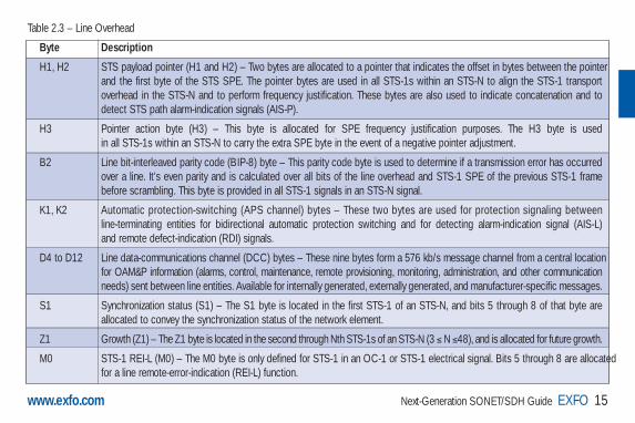
Table 2.3 – Line Overhead
Byte Description
H1, H2 STS payload pointer (H1 and H2) – Two bytes are allocated to a pointer that indicates the offset in bytes between the pointerand the first byte of the STS SPE. The pointer bytes are used in all STS-1s within an STS-N to align the STS-1 transport overhead in the STS-N and to perform frequency justification. These bytes are also used to indicate concatenation and to detect STS path alarm-indication signals (AIS-P).
H3 Pointer action byte (H3) – This byte is allocated for SPE frequency justification purposes. The H3 byte is used in all STS-1s within an STS-N to carry the extra SPE byte in the event of a negative pointer adjustment.
B2 Line bit-interleaved parity code (BIP-8) byte – This parity code byte is used to determine if a transmission error has occurredover a line. It’s even parity and is calculated over all bits of the line overhead and STS-1 SPE of the previous STS-1 frame before scrambling. This byte is provided in all STS-1 signals in an STS-N signal.
K1, K2 Automatic protection-switching (APS channel) bytes – These two bytes are used for protection signaling between line-terminating entities for bidirectional automatic protection switching and for detecting alarm-indication signal (AIS-L) and remote defect-indication (RDI) signals.
D4 to D12 Line data-communications channel (DCC) bytes – These nine bytes form a 576 kb/s message channel from a central locationfor OAM&P information (alarms, control, maintenance, remote provisioning, monitoring, administration, and other communicationneeds) sent between line entities. Available for internally generated, externally generated, and manufacturer-specific messages.
S1 Synchronization status (S1) – The S1 byte is located in the first STS-1 of an STS-N, and bits 5 through 8 of that byte are allocated to convey the synchronization status of the network element.
Z1 Growth (Z1) – The Z1 byte is located in the second through Nth STS-1s of an STS-N (3 ≤ N ≤48), and is allocated for future growth.
M0 STS-1 REI-L (M0) – The M0 byte is only defined for STS-1 in an OC-1 or STS-1 electrical signal. Bits 5 through 8 are allocatedfor a line remote-error-indication (REI-L) function.
Guide NEXT-GEN.3-ang: Guide Ethernet.1AN 5/7/07 11:31 AM Page 15

16 Next-Generation SONET/SDH Guide EXFO www.exfo.com
Table 2.3 – Line Overhead (continued)
Byte Description
M0 STS-1 REI-L (M0) – The M0 byte is only defined for STS-1 in an OC-1 or STS-1 electrical signal. Bits 5 through 8 are allocatedfor a line remote-error-indication (REI-L) function.
M1 STS-N REI-L (M1) – The M1 byte is located in the third STS-1 (in order of appearance in the byte-interleaved STS-N electricalor OC-N signal) in an STS-N (N ≤ 3), and is used for a REI-L function.
Z2 Growth (Z2) – The Z2 byte is located in the first and second STS-1s of an STS-3, and the first, second, and fourth through Nth STS-1s of an STS-N (12 ≤ N ≤ 48). These bytes are allocated for future growth.
E2 Orderwire byte – This orderwire byte provides a 64 kb/s voice channel between line entities.
• Path Overhead: In addition to user data, the SPE contains path overhead (POH) bytes; namely, high-order and low-order path overhead.
- Low-Order Path Overhead: In the case of a virtual signal, the VT POH (also known as low-order POH) contains four evenly distributed POH bytes per VT SPE, starting at the first byte of the VT SPE. VT POH provides means for communication between the point of creationof a VT SPE and its point of disassembly. Table 2.4a lists the VT POH bytes and their corresponding functions.
Table 2.4a – Low-Order Path Overhead
Byte Description
V5 This byte provides the same functions for the VT paths as the B3, C2 and G1 bytes provide for STS paths, including error checking, signal labeling, and path status indication.
J2 This byte is a VT path trace identifier used to transmit repetitive fixed-length messages (typically 16 or 64 bytes in sequence length).
Z6 This byte provides support for low-order tandem-connection monitoring.
Z7 This byte is used to enable APS signaling and extended RDI (ERDI) capability.
Guide NEXT-GEN.3-ang: Guide Ethernet.1AN 5/7/07 11:31 AM Page 16

Next-Generation SONET/SDH Guide EXFO 17www.exfo.com
- High-Order Path Overhead: The POH bytes, also known as STS POH or high-order POH, are processed at the SONET STS-1 terminatingequipment because they travel as part of the payload envelope. The SPE contains nine bytes of POH supporting functions such asperformance monitoring of the STS SPE, signal label, path status, and path trace. The path overhead is found in Rows 1 to 9 of the firstcolumn of the STS-1 SPE. Table 2.4b lists the POH bytes and their corresponding functions.
Table 2.4b – High-Order Path Overhead
Byte Description
J1 STS path trace byte – This user-programmable byte repetitively transmits a 64-byte, or 16-byte format string allowing the receiving terminal in a path to verify its continued connection to the intended transmitting terminal.
B3 STS path bit-interleaved parity code (Path BIP-8) byte – This is a parity code (even), used to determine if a transmission errorhas occurred over a path.
C2 STS path signal label byte – This byte is used to indicate the content of the STS SPE, including the status of the mapped payloads.
G1 Path status byte – This byte is used to convey the path-terminating status and performance back to the originating path-terminating equipment. Bits 1 through 4 are allocated for an STS Path REI function (REI-P). Bits 5, 6, and 7 of the G1 byte are allocated for an STS Path RDI (RDI-P) signal. Bit 8 of the G1 byte is currently undefined.
F2 Path user-channel byte – This byte is used for user communication between path elements.
H4 Virtual tributary (VT) multiframe indicator byte – This byte provides a generalized multiframe indicator for payload containers. At present, it is used for tributary unit structured payloads, as well as virtual concatenation functions.
Guide NEXT-GEN.3-ang: Guide Ethernet.1AN 5/7/07 11:31 AM Page 17

www.exfo.com18 Next-Generation SONET/SDH Guide EXFO
2.4.2 STM-1 Frame Format
The STM-1 frame is the basic transmission format forSDH. Figure 2.6 illustrates the basic SDH framestructure. The STM-1 frame consists of overhead plus avirtual container payload. The first nine columns of eachframe make up the section overhead (SOH), and the last261 columns make up the virtual container (VC)payload. The VC plus the pointers (H1, H2, and H3bytes) is called the administrative unit (AU). The VC hasits own frame structure of nine rows and 261 columns,and it carries both the path overhead (POH) and thecontainer. The first column is for path overhead, followedby the payload container, which can itself carry othercontainers. Within the section overhead, the first threerows are used for the regenerator section overhead, and the last five rows are used for the multiplex section overhead.
9 bytes 261 bytes
260 columns (bytes)VC-4
270 columns (bytes)
RegeneratorSection Overhead
RSOH
AU Pointer
MultiplexSection Overhead
MSOH
Au-4
C-4Data payloadPOH
1
3
4
5
9
9 rows(bytes)
Figure 2.6 STM-1 Frame Format
Guide NEXT-GEN.3-ang: Guide Ethernet.1AN 5/7/07 11:31 AM Page 18

Next-Generation SONET/SDH Guide EXFO 19www.exfo.com
SDH Overhead
The SDH overhead information has several layers(shown in Figure 2.7): the regenerator sectionoverhead, the multiplex section overhead, the high-order path overhead, and the low-order pathoverhead. The following sections detail the differentSDH overhead information:• Regenerator Section Overhead: This layer
contains only the information required for theelements located at both ends of a section.This might be two regenerators, a line-terminating equipment component and aregenerator, or two line-terminating equipmentcomponents. The regenerator section overheadis found in the first three rows of Columns 1through 9 of the STM-1 frame. Table 2.5 liststhe regenerator section overhead bytes andtheir corresponding functions.
A1 A1 A1
B1
D1
H1
B2 B2 B2
D4
D7
D10
S1
A2
E1
D2
H2
K1
D5
D8
D11
A2
1
A2
1
M1
J0
F1
D3
H3
K2
D6
D9
D12
E2
H3 H3
RSOH
9 rows
MSOH
J1
B3
C2
G1
F2
H4
F3
K3
N1
V5
J2
N2
K4
AU Pointer
9 Bytes
HO-POH
LO-POH
Figure 2.7 SDH Overhead Format
Guide NEXT-GEN.3-ang: Guide Ethernet.1AN 5/7/07 11:31 AM Page 19
20 Next-Generation SONET/SDH Guide EXFO www.exfo.com
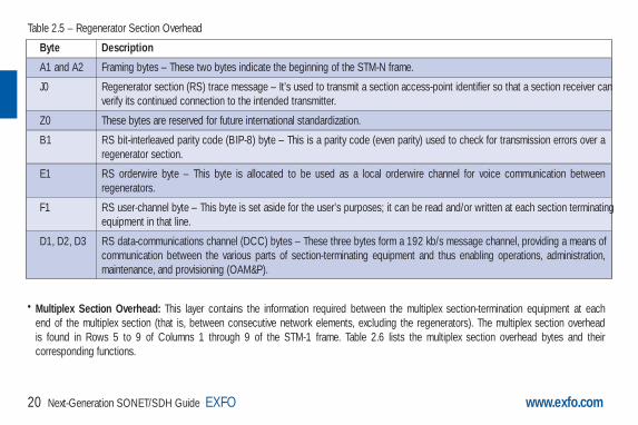
Table 2.5 – Regenerator Section Overhead
Byte Description
A1 and A2 Framing bytes – These two bytes indicate the beginning of the STM-N frame.
J0 Regenerator section (RS) trace message – It’s used to transmit a section access-point identifier so that a section receiver canverify its continued connection to the intended transmitter.
Z0 These bytes are reserved for future international standardization.
B1 RS bit-interleaved parity code (BIP-8) byte – This is a parity code (even parity) used to check for transmission errors over a regenerator section.
E1 RS orderwire byte – This byte is allocated to be used as a local orderwire channel for voice communication between regenerators.
F1 RS user-channel byte – This byte is set aside for the user’s purposes; it can be read and/or written at each section terminatingequipment in that line.
D1, D2, D3 RS data-communications channel (DCC) bytes – These three bytes form a 192 kb/s message channel, providing a means ofcommunication between the various parts of section-terminating equipment and thus enabling operations, administration,maintenance, and provisioning (OAM&P).
• Multiplex Section Overhead: This layer contains the information required between the multiplex section-termination equipment at each end of the multiplex section (that is, between consecutive network elements, excluding the regenerators). The multiplex section overhead is found in Rows 5 to 9 of Columns 1 through 9 of the STM-1 frame. Table 2.6 lists the multiplex section overhead bytes and theircorresponding functions.
Guide NEXT-GEN.3-ang: Guide Ethernet.1AN 5/7/07 11:31 AM Page 20

www.exfo.com Next-Generation SONET/SDH Guide EXFO 21
Table 2.6 – Multiplex Section Overhead
Byte Description
B2 Multiplex section (MS) bit-interleaved parity code (MS BIP-24) byte – Provides multiplex section error monitoring. The BIP-N x24 of an STM-N frame provides end-to-end error performance monitoring across an individual multiplex section and is calculatedover all bits of the previous STM-N frame, except for the first three rows of SOH.
K1, K2 Automatic protection switching (APS channel) bytes – These two bytes are used for multiplex section protection (MSP) signaling between multiplex level entities for bidirectional automatic protection switching and for communicating alarm indicationsignals (AISs) and remote defect indications (RDIs).
D4 to D12 MS data-communications channel (DCC) bytes – These nine bytes form a 576 kb/s message channel from a central locationfor OAM information (control, maintenance, remote provisioning, monitoring, administration and other communication needs).
S1 Synchronization status message byte (SSMB) – Bits 5 to 8 of this S1 byte are used to carry the synchronization messages.
M1 MS remote error indication – The M1 byte of an STM-1 or the first STM-1 of an STM-N is used for an MS layer remote error indication (MS-REI).
E2 MS orderwire byte – This orderwire byte provides a 64 kb/s voice channel between multiplex entities for an express orderwire.
• Higher-Order Path Overhead (VC-3/VC-4): The path overhead is assigned to, and transported with, the virtual container from the time it iscreated by path-terminating equipment until the payload is demultiplexed at the termination point in path-terminating equipment component.The path overhead is found in Rows 1 to 9 of the first column of the VC-4 or VC-3. Table 2.7 lists the higher-order path overhead bytes andtheir corresponding functions.
Guide NEXT-GEN.3-ang: Guide Ethernet.1AN 5/7/07 11:31 AM Page 21

22 Next-Generation SONET/SDH Guide EXFO www.exfo.com
Table 2.7 – Higher-Order Path Overhead (VC-3/VC-4)
Byte Description
J1 Higher-order VC-N path trace byte – This user-programmable byte repetitively transmits a 16-byte or 64-byte free-format stringallowing the receiving terminal in a path to verify its continued connection to the intended transmitting terminal.
B3 Path bit-interleaved parity code (Path BIP-8) byte – This is a parity code (even), used to determine if a transmission error hasoccurred over a path.
C2 Path signal label byte – This byte specifies the mapping type in the VC-N.
G1 Path status byte – This byte is used to convey the path-terminating status and performance back to the originating path-terminating equipment.
F2 Path user-channel byte – This byte is used for user communication between path elements.
H4 Position and sequence indicator byte – This byte provides a multiframe and sequence indicator for virtual VC-3/4 concatenation and a generalized position indicator for payloads.
F3 Path user-channel byte – This byte is allocated for communication purposes between path elements and is payload-dependent.
K3 APS signaling is provided in K3 bits 1-4, allocated for protection at the VC-4/3 path levels. K3 bits 5-8 are allocated for future use.
N1 Network operator byte – This byte is allocated to provide a higher-order tandem connection monitoring (HO-TCM) function.
• Lower-Order Path Overhead (VC-11/VC-12): These bytes are allocated to the VC-11/VC-12 POH. Table 2.8 lists the lower-order pathoverhead bytes and their corresponding functions.
Guide NEXT-GEN.3-ang: Guide Ethernet.1AN 5/7/07 11:31 AM Page 22

Next-Generation SONET/SDH Guide EXFO 23www.exfo.com
Table 2.8 – Lower-Order Path Overhead (VC-11/VC-12)
Byte Description
V5 VT path overhead byte.
J2 Used to repetitively transmit a lower-order access path identifier so that a path-receiving terminal can verify its continued connection to the intended transmitter. A 16-byte frame is defined for the transmission of path access-point identifiers. This 16-byte frame is identical to the 16-byte frame of the J1 and J0 bytes.
N2 Allocated for tandem connection monitoring for the VC2, VC-12, and VC-11 level.
K4 Bit 1 is used for multiframe alignment signals and extended signal labels, whereas Bit 2 is used for virtual concatenation.
2.5 Virtual Tributaries/ContainersAs mentioned, one of the advantages of the SONET/SDH standard is that it will transport all of the lower-rate signals by mapping them into“sections” of an STS-1 or STM-1 frame, called virtual tributaries in SONET and virtual container in SDH. In SONET, a virtual tributary informationis organized inside an STS-1 channel of SONET frames and routed through the network to a specified destination from a given source location.Each of the virtual tributary sections is independent of the others and can carry a different type of payload.
Guide NEXT-GEN.3-ang: Guide Ethernet.1AN 5/7/07 11:31 AM Page 23

2.5.1 SONET Virtual Tributaries
Currently, there are four virtual tributary sizes defined in SONET:
• VT1.5: Carries enough bandwidth to transport a DS-1 signal of 24 DS-0s at 64 kb/s. Each is contained in three 9-byte columns (27 bytes).A single VTG can carry 4 VT1.5s.
• VT2: Carries enough bandwidth to transport an E-1, 2.048 Mb/s signal. It is contained in four 9-byte columns (36 bytes).
• VT3: Carries enough bandwidth to transport a DS-1C signal. It is contained in six 9-byte columns (54 bytes).
• VT6: Carries enough bandwidth to transport a DS-2 signal. It is contained in twelve 9-byte columns (108 bytes).
The different-size tributary options are provided to maximize available bandwidth in an STS-1 channel. For example, if the end user requires thetransport of DS-1C signals requiring 3.152 Mb/s, a size VT3 virtual tributary would be the ideal solution, as opposed to a size VT6, which providesmuch more bandwidth than what is needed. Other common low-rate signals such as DS1, E1, and DS2 fit into virtual tributary types VT1.5, VT2,and VT6, respectively.
The virtual tributary structure contains three main components consisting of the payload pointer (VT payload pointer), path overhead (VT POH),and payload data bytes. Together, the path overhead and payload data form what is called the VT synchronous payload envelope (SPE). Each virtual tributary type has a unique VT SPE size. Although the number of payload bytes in the VT SPE differs for each virtual tributary size, the number of VT POH bytes and functionality of each is the same, regardless of the VT type.
24 Next-Generation SONET/SDH Guide EXFO www.exfo.com
Guide NEXT-GEN.3-ang: Guide Ethernet.1AN 5/7/07 11:31 AM Page 24

Next-Generation SONET/SDH Guide EXFO 25www.exfo.com
Figure 2.8 illustrates four VT POH bytes contained in any VTstructure separated by a fixed number of payload bytes. The first byteof the VT SPE is always the V5 VT POH byte. V5 is used to providetributary BIP-2 parity (provides error performance monitoring), REI-V(remote error indication used to indicate BIP-2 errors at originatingequipment), RFI-V (remote failure indication), signal label (indicatescontent of VT SPE), and RDI-V (remote defect indication)information.
2.5.2 SDH Virtual Tributaries
SDH, on the other hand, supports a concept called virtual containers(VC). Through the use of pointers and offset values, VCs can becarried in the SDH payload as independent data packages. VCs areused to transport lower-speed tributary signals. A basic SDH framehas a capacity of 155 Mb/s, which means that it can either transportone VC-4 virtual container or three VC-3 virtual containers. Thepayload of each of these containers can be one high-rate tributary ora combination of tributary unit groups that contain low-rate signals.
V5 (VT POH)
25 payload bytes
J2 (VT POH)
25 payload bytes
Z6 (VT POH)
25 payload bytes
Z7 (VT POH)
25 payload bytes
V5 (VT POH)
34 payload bytes
J2 (VT POH)
34 payload bytes
Z6 (VT POH)
34 payload bytes
Z7 (VT POH)
34 payload bytes
V5 (VT POH)
52 payload bytes
J2 (VT POH)
52 payload bytes
Z6 (VT POH)
52 payload bytes
Z7 (VT POH)
52 payload bytes
V5 (VT POH)
106 payload bytes
J2 (VT POH)
106 payload bytes
Z6 (VT POH)
106 payload bytes
Z7 (VT POH)
106 payload bytes
VT SPE — VT1.5 VT SPE — VT2 VT SPE — VT3 VT SPE — VT6
Figure 2.8 SONET Virtual Tributary Structures
Guide NEXT-GEN.3-ang: Guide Ethernet.1AN 5/7/07 11:31 AM Page 25

26 Next-Generation SONET/SDH Guide EXFO www.exfo.com
As for low-speed signals, VC-12 (and, likewise, VC-2 and VC-11) must be transported in other containers with a greater capacity (VC-3 or VC-4) before being introduced in the STM-1 frame. The containers with a greater capacity can transport up to 63 VC-12s in the STM-1frame. The VC-4 container has 63 pointers that find the location of each of the VC-12s transported with respect to the VC-4. The following arethe currently defined virtual container sizes in the SDH standard:
• VC-11: Carries enough bandwidth to transport 1.728 Mb/s. Each is contained in 9 rows, 3 columns (27 bytes).
• VC-12: Carries enough bandwidth to transport 2.304 Mb/s. Each is contained in 9 rows, 4 columns (36 bytes).
• VC-2: Carries enough bandwidth to transport 6.912 Mb/s. Each is contained in 9 rows, 12 columns (108 bytes).
• VC-3: Carries enough bandwidth to transport 48.960 Mb/s. Each is contained in 9 rows, 85 columns (765 bytes).
• VC-4: Carries enough bandwidth to transport 150.336 Mb/s. Each is contained in 9 rows, 261 columns (2,349 bytes).
Guide NEXT-GEN.3-ang: Guide Ethernet.1AN 5/7/07 11:31 AM Page 26

Why Next-Generation SONET/SDH?
Guide NEXT-GEN.3-ang: Guide Ethernet.1AN 5/7/07 11:31 AM Page 27

28 Next-Generation SONET/SDH Guide EXFO www.exfo.com
3. Why Next-Generation SONET/SDH?Simply stated, next-generation SONET/SDH has gained a significant momentum in the industry as its associated technologies have allowedSONET/SDH to evolve with the times and offer an efficient means of transporting packet-based services over the widely deployed SONET/SDH networks.
As described above, SONET/SDH standards have their roots in the multiplexing and transport of voice channels, as well as private line ATM andFrame Relay services; therefore, they have not been designed to transport data services such as Ethernet, resulting in several limiting factors whenattempting to transport packet-based services:
SONET/SDH transport rates are not ideally suited for transporting packet interfaces such as Ethernet and Fibre Channel: The lowest datarate that can be carried on SONET is 1.544 Mb/s. Slower rates can be carried, but it requires tying up the entire bandwidth capacity; i.e., 1.544 Mb/s. The rates go up from there (approximate values): 2 Mb/s, 3 Mb/s, 6 Mb/s, 34 Mb/s, 45 Mb/s, 139 Mb/s, 155 Mb/s, 622 Mb/s,2.5 Gb/s, and 10 Gb/s. Rates between those values could only be carried by using the next higher bandwidth, an inefficient arrangement. For example, Gigabit Ethernet circuits (at a bandwidth of 1 Gb/s) can only be carried on 2.5 Gb/s, thus wasting over half the available bandwidth.
SONET/SDH has no built-in capability for dynamically shifting bandwidth usage: In order to efficiently use bandwidth, it can be veryadvantageous to shift usage based on time of day or other factors. For example, a financial institution may need bandwidth only during business hours.If the organization were connected directly to a SONET/SDH circuit, that bandwidth would be tied up all the time, even during nights and weekends.
SONET/SDH has no common data mapping scheme: Frame Relay, ATM, and Packet-over-SONET (PoS) are the dominant service-layertechnologies for data service delivery over traditional SONET/SDH networks. More recently, Ethernet over LAPS (also known as X.86) hasemerged for Ethernet service delivery over SONET/SDH networks. The common issue with these technologies is that they are client-service-specific, and do not represent a common traffic adaptation scheme for a wide range of data services (i.e., Ethernet, Fibre Channel, IP/PPP, etc.).
Guide NEXT-GEN.3-ang: Guide Ethernet.1AN 5/7/07 11:31 AM Page 28

Next-Generation SONET/SDH Guide EXFO 29www.exfo.com
As mentioned earlier, Ethernet has become the Layer 2 technology of choice for both enterprise connectivity and access aggregation networks.As service providers had invested heavily in their SONET/SDH networks and they found the technology to be reliable, there was great incentiveto keep using the existing infrastructure to meet Ethernet demand.
As a consequence, in 1999, work was initiated within the ITU-T & ANSI standards bodies to define technologies that would help SONET/SDHevolve with the times and offer efficient means of transporting these packet-based services over the widely deployed SONET/SDH networks. Their answer: the definition and ratification of three key technologies that form the basis of next-generation SONET/SDH: generic framingprocedure (GFP), virtual concatenation (VCAT), and link-capacity-adjustment scheme (LCAS).
The following sections provide an in-depth look into these three key next-generation SONET/SDH technologies, outlining their key applications innext-generation networking.
Guide NEXT-GEN.3-ang: Guide Ethernet.1AN 5/7/07 11:31 AM Page 29

Generic Framing Procedure (GFP)
Guide NEXT-GEN.3-ang: Guide Ethernet.1AN 5/7/07 11:31 AM Page 30

Next-Generation SONET/SDH Guide EXFO 31www.exfo.com
4. Generic Framing Procedure (GFP)Generic framing procedure (GFP), defined in ITU recommendation G.7041/Y.1303, is a framing mechanism to transport packet-based clientsignals, such as Ethernet, Fibre Channel, ESCON, FICON, over fixed-data-rate optical channels. As such, GFP provides a single, flexiblemechanism to map these client signals into SONET/SDH and OTN networks, as shown in Figure 4.1 below.
Prior to the introduction of GFP, several methods had beenused to transport packet services over SONET/SDHnetworks. The first method was Asynchronous TransferMode (ATM) Adaptation Layer 5 (AAL 5) over SONET/SDH.ATM is a very efficient switching and multiplexing technology,whose transfer rates scale with SONET/SDH rates.However, ATM does not make the most efficient use ofbandwidth because the payload data is separated intogroups of 48 bytes, called cells, with an additional 5-byteheader of software overhead. It became immediatelyapparent that almost 10% of the bandwidth would be lost. In addition, certain types of data required even more ATM overhead.
Other methods have focused on using point-to-pointprotocol (PPP). The IP traffic coming to an Ethernet port isencapsulated over a PPP link and multiple ports can beencapsulated over multilink PPP (ML-PPP) links. By using anHDLC framing, the PPP traffic is transported over theSONET/SDH payload. These methods have beenstandardized within the IETF through the following Requests
Voice SANs VideoData (IP, IPX, MPLS, etc.)
Privatelines
Ethernet*
RPR
FR POS
ESC
ON*
FIC
ON*
DVI*
Fibr
e C
hann
el*
HDLC*
ATM GFP
SONET/SDH
WDM/OTN
Fiber
Figure 4.1 Client Signal Mapping over GFP
Guide NEXT-GEN.3-ang: Guide Ethernet.1AN 5/7/07 11:31 AM Page 31

32 Next-Generation SONET/SDH Guide EXFO www.exfo.com
for Comments (RFC): RFC 1662, RFC 1990 and RFC 2615. The ITU-T expanded this work by specifying the use of LAPS (very similar protocolto PPP/HDLC) and specifying IP over LAPS in X.85/Y.1321 and Ethernet over LAPS in X.86/Y1323. All these methods for encapsulating trafficsuffer from the weaknesses of HDLC framing; i.e., limited protection from frame corruption and the introduction of variable packet sizes becauseof its trailer.
GFP has been standardized to better optimize the transport of Ethernet and other data services over SONET/SDH networks, taking into accountboth the pros and cons of ATM and PPP/HDLC and leveraging two new emerging SONET/SDH capabilities, VCAT and LCAS, that will bediscussed later in this document.
4.1 GFP MappingTwo types of mapping are currently available for GFP: framed-mapped (GFP-F) and transparent-mapped (GFP-T), whose mappings keep the samebasic frame structure, as will be shown in the next sections. The decision on which mode to use is dependent on the underlying service to betransported.
Frame-Mapped GFP (GFP-F) is mapping mechanism in which one client signal frame is received and mapped in its entirety into one GFPframe. Therefore, with this adaptation mode, the GFP-F frame size is variable as it is directly related to the incoming client payload. In fact,with GFP-F, the entire client frame must be buffered in order to determine its length. GFP-F is usually used to support Layer 2 frames likeEthernet MAC that are tolerant to some latency. The ITU G.7041 defines the following frame-mapped user payloads supported through GFP-F:
• Frame-Mapped Ethernet
• Frame-Mapped PPP
• Frame-Mapped Multiple Access Protocol over SDH (MAPOS)
• Framed-Mapped IEEE 802.17 Resilient Packet Ring
• Frame-Mapped Fibre Channel FC-BBW
Guide NEXT-GEN.3-ang: Guide Ethernet.1AN 5/7/07 11:31 AM Page 32
Next-Generation SONET/SDH Guide EXFO 33
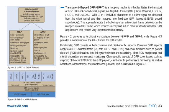
Transparent-Mapped GFP (GFP-T) is a mapping mechanism that facilitates the transportof 8B/10B block-coded client signals like Gigabit Ethernet (GbE), Fibre Channel, ESCON,FICON, and DVB-ASI. With GFP-T, individual characters of a client signal are decodedfrom the client signal and then mapped into fixed-size GFP frames (64B/65 codedsuperblocks). This approach avoids the buffering of an entire client frame before it can bemapped into a GFP frame, which reduces latency and in turn makes it ideally suited for SANapplications that require very low transmission latency.
Figure 4.2 provides a functional comparison between GFP-F and GFP-T, while Figure 4.3provides a comparison of the GFP frames for both modes.
Functionally, GFP consists of both common and client-specific aspects. Common GFP aspectsapply to all GFP-adapted traffic (i.e., both GFP-F and GFP-T) and cover functions such as packetdata unit (PDU) delineation, data link synchronization and scrambling, client PDU multiplexing, andclient-independent performance monitoring. Client-specific aspects of GFP cover issues such asmapping of the client PDU into the GFP payload, client-specific performance monitoring, as well asoperations, administration, and maintenance (OA&M). This is illustrated in Figure 4.1.
www.exfo.com
GFP-F and GFP-T Common Features
GFP-T
Multiple service support Efficiency tailored for client type
Bandwidth utilization Excellent error control
Fixed frame length N to 1 mapping of client packet Operates on arriving bytes Buffering not required No latency No MAC required (only 8B/10B) Optimized for Fibre channel (FC), FICON, ESCON, and Storage Area Networks (SANs)
GFP-FVariable frame length 1:1 mapping of client packet Operates on entire frame Buffering required Latency MAC awareness Optimized for IP, PPP, Ethernet, GbE and MPLS
Figure 4.2 GFP-T vs. GFP-F Features
Ethe
rnet
IP/P
PP
MAP
OS
RPR
FIC
ON
ESC
ON
Oth
ercli
ent
signa
ls
Fibr
eC
hann
el
GFP client-specific aspects(client-dependent)
GFP common aspects(client-independent)
Frame mapped Transparent mapped
SONET/SDH path OTN ODUk path
Figure 4.3 GFP-T vs. GFP-F Frames
Guide NEXT-GEN.3-ang: Guide Ethernet.1AN 5/7/07 11:31 AM Page 33
34 Next-Generation SONET/SDH Guide EXFO www.exfo.com
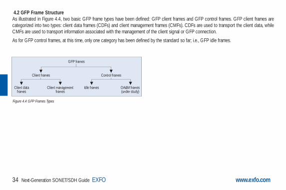
4.2 GFP Frame StructureAs illustrated in Figure 4.4, two basic GFP frame types have been defined: GFP client frames and GFP control frames. GFP client frames arecategorized into two types: client data frames (CDFs) and client management frames (CMFs). CDFs are used to transport the client data, whileCMFs are used to transport information associated with the management of the client signal or GFP connection.
As for GFP control frames, at this time, only one category has been defined by the standard so far; i.e., GFP idle frames.
GFP frames
Client frames Control frames
Client dataframes
Client managementframes
Idle frames OA&M frames(under study)
Figure 4.4 GFP Frames Types
Guide NEXT-GEN.3-ang: Guide Ethernet.1AN 5/7/07 11:31 AM Page 34

Next-Generation SONET/SDH Guide EXFO 35www.exfo.com
The GFP generic frame structure is presented inFigure 4.5.
Each GFP frame type consists of three maincomponents: the core header, the payload header,and the payload information field.
The core and payload headers form the GFP header,whereas the payload information field represents thecustomer traffic carrying the data services. The payloadheader carries information about the payload type(i.e., Ethernet, Fibre Channel, etc.) that it is carrying,while the core header carries information about thesize of the GFP frame itself.
Each header contains a header error correction(HEC) calculation, allowing for the correction ofsingle errors; that is, any errors that occur in the coreheader or in the payload header can potentially becorrected by the HEC, through the network element.This creates a very robust mapping scheme, whichensures that GFP frames can get transported acrossa network without customer traffic loss.
Core Header
Payload TypeIndentifier
(PTI) (3 bits)User Payload
Indentifier(UPI) (1 byte)
Type HEC (tHEC)(CRC-16, 2 bytes)
Channel ID(CID) (byte)
Spare( 1 byte)
Extension HEC (eHEC)(CRC-16, 2 bytes)
Payload FCSIndicator
(PFI) (1 bit)
Extension HeaderIdentifier
(EXI) (4 bits)
Payload Length Indicator(PLI)
(2 bytes)
Core HEC (cHEC)(CRC-16, 2 bytes)
Payload Area
Payload Header(4-64 bytes)
Payload InformationField
Payload FCS(Optional)(CRC-32)
4 bytes
0 to 65535 – X bytes
X = 4 to 64 bytes
Linear frames only
Figure 4.5 GFP Generic Frame Structure
Guide NEXT-GEN.3-ang: Guide Ethernet.1AN 5/7/07 11:31 AM Page 35
36 Next-Generation SONET/SDH Guide EXFO www.exfo.com
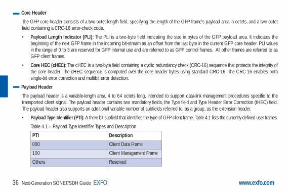
Core Header
The GFP core header consists of a two-octet length field, specifying the length of the GFP frame's payload area in octets, and a two-octetfield containing a CRC-16 error-check code.
• Payload Length Indicator (PLI): The PLI is a two-byte field indicating the size in bytes of the GFP payload area. It indicates thebeginning of the next GFP frame in the incoming bit-stream as an offset from the last byte in the current GFP core header. PLI valuesin the range of 0 to 3 are reserved for GFP internal use and are referred to as GFP control frames. All other frames are referred to asGFP client frames.
• Core HEC (cHEC): The cHEC is a two-byte field containing a cyclic redundancy check (CRC-16) sequence that protects the integrity ofthe core header. The cHEC sequence is computed over the core header bytes using standard CRC-16. The CRC-16 enables bothsingle-bit error correction and multibit error detection.
Payload Header
The payload header is a variable-length area, 4 to 64 octets long, intended to support data-link management procedures specific to thetransported client signal. The payload header contains two mandatory fields, the Type field and Type Header Error Correction (tHEC) field.The payload header also supports an additional variable number of subfields referred to, as a group, as the extension header.
• Payload Type Identifier (PTI): A three-bit subfield that identifies the type of GFP client frame. Table 4.1 lists the currently defined user frames.
Table 4.1 – Payload Type Identifier Types and Description
PTI Description
000 Client Data Frame
100 Client Management Frame
Others Reserved
Guide NEXT-GEN.3-ang: Guide Ethernet.1AN 5/7/07 11:31 AM Page 36

Next-Generation SONET/SDH Guide EXFO 37www.exfo.com
• Payload FCS Indicator (PFI): A one-bit subfield indicating the presence (1) or absence (0) of the payload FCS field. Table 4.2 liststhe currently defined PFI values.
Table 4.2 – Payload FCS Indicator Values and Description
PFI Description
0 FCS Absent
1 FCS Present
• Extension Header Identifier (EXI): A four-bit subfield identifying the type of GFP extension header. Three kinds of extension headersare currently defined.
Table 4.3 – Extension Header Identifier Values and Description
EXI Description Function
0000 Null Extension Header Indicates that no extension header is present.
0001 Linear Extension Header A two-octet extension header that supports sharing of the GFP payload acrossmultiple clients in a point-to-point configuration. The linear extension header consists ofan eight-bit channel ID (CID) field, used to indicate one of 256 communicationchannels (i.e. clients) at a GFP termination point, and an eight-bit spare fieldreserved for future use.
0010 Ring Extension Header The use of this field is under consideration. Similar to linear, the current proposalbeing considered is to allow the sharing of the GFP payload across multiple clients;however, this would only apply to ring configurations.
From 0011 to 1111 Reserved
Guide NEXT-GEN.3-ang: Guide Ethernet.1AN 5/7/07 11:31 AM Page 37

www.exfo.com38 Next-Generation SONET/SDH Guide EXFO
• User Payload Identifier (UPI): An eight-bit field identifying the type of payload conveyed in the GFP payload information field:
Table 4.4 – User Payload Identifier (UPI) Values and Description
UPI Client Data Client Management
0000 0000 Reserved and not available Reserved1111 11110000 0001 Mapped Ethernet Frame Client Signal Fail (Loss of Client Signal)
0000 0010 Mapped PPP Frame Client Signal Fail (Loss of Character Synchronization)
0000 0011 Transparent Fibre Channel
0000 0100 Transparent FICON
0000 0101 Transparent ESCON
0000 0110 Transparent GbE
0000 0111 Reserved for future use Reserved for future use
0000 1000 Frame-Mapped IEEE 802.17 Resilient Packet Ring
0000 1011 Frame-Mapped Fibre Channel FC-BBW0000 1100 Asynchronous Transparent Fibre Channel
0000 1101 through 1110 1111 Reserved for future standardization
1111 0000 through 1111 1110 Reserved for proprietary use
Guide NEXT-GEN.3-ang: Guide Ethernet.1AN 5/7/07 11:31 AM Page 38

Next-Generation SONET/SDH Guide EXFO 39www.exfo.com
• Type HEC (tHEC) Field: A two-octet field that contains a CRC-16 sequence to protect the integrity of the type field. The tHEC sequence is computed over the core header bytes using standard CRC-16. As with the cHEC, CRC-16 enables both single-bit error correction and multibit error detection.
• Channel Identifier (CID): A one-byte field that is only available when the EXI field is configured to Linear. The CID byte is used to indicate one of 256 communication channels at a GFP termination point.
• Spare: A one-byte field that is only available when the EXI fieldis configured to Linear. This field is reserved for future use.
• Extension HEC (eHEC): A two-byte field that contains aCRC-16 check sequence that protects the integrity of thecontents of the extension. CRC-16 enables both single-bitcorrection and multibit error detection.Figure 4.6 explains how (in GFP-F) the transmitterencapsulates one entire frame of the client data.
Payload Information Field
The payload area (also referred to as payload informationfield) contains the framed client signal. This variable-lengthfield may include from 0 to 65,535 – X octets, where X isthe size of the payload header (including the extensionheader, if present) and the payload FCS field (if present). Figure 4.3 above shows the GFP-T and GFP-T framestructures. As shown, both frame types share a commoncore header, payload header, and payload FCS (optional),and they differ in the way in which the client is mapped intothis payload area.
PLI
2 bytes
cHEC
2 bytes
Payloadheader
4 to 64 bytes
FCS(optional)4 bytes
Client PDU(PPP, IP, Ethernet, RPR, etc.)
0 to 65536 – X bytes where X = Payload header
PLI
2 bytes
cHEC
2 bytes
Payloadheader
4 to 64 bytes
FCS(optional)4 bytes
8 x 64B/65B + 16superblock bits# 1 # 2 #N-1 # N
64B/65B #1 1 CCL#1 CCI#1
n CCL#n CCI#nDCI#1
DCI#8-n
64B/65B #2
64B/65B #N-164B/65B #NF1 F2 ..._ F8
CRC-16 MSBCRC-16 LSB
GFPHeader
GFPFCS
GFPpayload
GFP-F frame
GFP-T frame
64B/65B superblock
(Flag bits carried inlast octet of the
superblock)
64B/65B block(minus flag bit)
Figure 4.6 GFP-F vs. GFP-T Frame Structure
Guide NEXT-GEN.3-ang: Guide Ethernet.1AN 5/7/07 11:31 AM Page 39
40 Next-Generation SONET/SDH Guide EXFO www.exfo.com
• Payload FCS (pFCS): This is an optional four-octet-long frame-checksequence. It contains a CRC-32 check sequence that is designed tovalidate the entire content of the payload area. The FCS fieldpresence is signaled by the PFI bit located in the Type field of thepayload header. The FCS does not correct any errors; it justindicates the presence of error(s).
In GFP-F, the transmitter encapsulates one entire frame of theclient data into one GFP frame. In this case, the basic framestructure of a GFP client frame is used, including the requiredpayload header.
In GFP-T, however, rather than buffering an entire client-dataframe, the individual characters of the client signal are demappedfrom the client block codes and then mapped into periodic fixed-length GFP frames. The transparent GFP client frame uses thesame structure as the frame-mapped GFP, including the requiredpayload header.
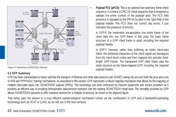
4.3 GFP SummaryGFP has been standardized to better optimize the transport of Ethernet and other data services over SONET, taking into account both the pros and consof ATM and PPP/HDLC framing mechanisms. As described in this section, GFP represents a robust mapping mechanism that allows for the mapping ofmultiple client-data types into SONET/SDH payload (SPEs). This technology has been embraced by network equipment and service providers as itprovides an efficient way of providing interoperable data-services transport over the existing SONET/SDH install base. The versatility provided by GFPallows SONET/SDH networks to offer transport services for a multiple of services, as shown in the adjacent figure.
That being said, the answer to a truly efficient packet-transport mechanism comes via the combination of GFP and a bandwidth-optimizingtechnology such as VCAT or LCAS, as we will see in the next sections.
Figure 4.7 Multiservice SONET/SDH Network
Guide NEXT-GEN.3-ang: Guide Ethernet.1AN 5/7/07 11:31 AM Page 40

Virtual Concatenation (VCAT)
Guide NEXT-GEN.3-ang: Guide Ethernet.1AN 5/7/07 11:31 AM Page 41
www.exfo.com42 Next-Generation SONET/SDH Guide EXFO
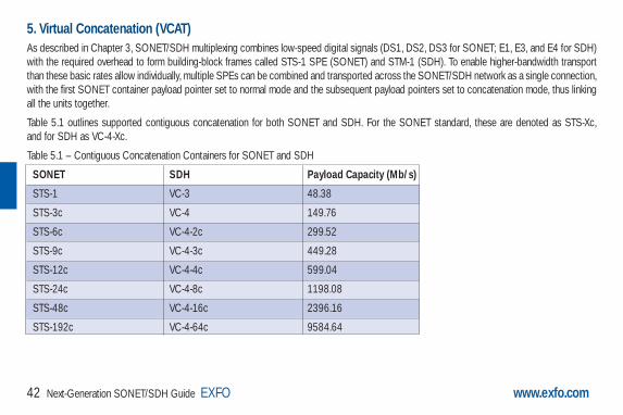
5. Virtual Concatenation (VCAT)As described in Chapter 3, SONET/SDH multiplexing combines low-speed digital signals (DS1, DS2, DS3 for SONET; E1, E3, and E4 for SDH)with the required overhead to form building-block frames called STS-1 SPE (SONET) and STM-1 (SDH). To enable higher-bandwidth transportthan these basic rates allow individually, multiple SPEs can be combined and transported across the SONET/SDH network as a single connection,with the first SONET container payload pointer set to normal mode and the subsequent payload pointers set to concatenation mode, thus linkingall the units together.
Table 5.1 outlines supported contiguous concatenation for both SONET and SDH. For the SONET standard, these are denoted as STS-Xc, and for SDH as VC-4-Xc.
Table 5.1 – Contiguous Concatenation Containers for SONET and SDH
SONET SDH Payload Capacity (Mb/s)
STS-1 VC-3 48.38
STS-3c VC-4 149.76
STS-6c VC-4-2c 299.52
STS-9c VC-4-3c 449.28
STS-12c VC-4-4c 599.04
STS-24c VC-4-8c 1198.08
STS-48c VC-4-16c 2396.16
STS-192c VC-4-64c 9584.64
Guide NEXT-GEN.3-ang: Guide Ethernet.1AN 5/7/07 11:31 AM Page 42

Next-Generation SONET/SDH Guide EXFO 43www.exfo.com
As described in Chapter 2, lower-rate virtual tributary signals have also been defined for both SONET and SDH, as shown in the table below:
Table 5.2 – Tributary Units for SONET and SDH
SONET SDH Payload Capacity (Mb/s)
VT 1.5 VC-11 1.6
VT 2 VC-12 2.17
VT 6 VC-2 6.78
Although contiguous concatenation has been successfully introduced and deployed for years, it poses some major deficiencies when attemptingto transport packet-based signals. First, in contiguous concatenation, the concatenated bandwidth requires the timeslots to be consecutive.Second, it also requires that the network elements involved in the transport of the traffic support this function from the source to the destinationnode, including every intermediate node. Third, data-service rates are not well matched to these defined containers, hence using GFP with currentcontiguous concatenation schemes results in sub-optimal use of the bandwidth, as Ethernet and Fibre Channel data rates are not properlymatched to these channels (e.g., 100M Ethernet service mapped over an STS-3c or VC4 results in approximately 33% of wasted bandwidth). To address these limitations, a complementary technology — virtual concatenation (VCAT) — was developed and later defined in ANSI T1.105, ITU G.707,and ITU G.783 recommendations. Two forms of virtual concatenation were defined; i.e., high-order and low-order VCAT. This introduced additionalflexibility to SONET/SDH by allowing for the non-contiguous concatenation of high-order or low-order payload frames to better scale therequirements for incremental client-data streams. This means that the concatenated payload does not need to be formed by consecutive timeslotsin the transport path. In addition, this new concatenation capability allows the network element involved in the transport of the traffic to be unawareof concatenated nature of the signal. As such, only the termination points in the transport path must support the VCAT functionality.
In essence, virtual concatenation is an inverse multiplexing procedure whereby the contiguous bandwidth is broken into individual SPEs at thesource transmitter and logically represents them in a virtual concatenation group (VCG). Control packets, which contain the necessary informationfor reassembling the original data stream at its destination PTE, are inserted in some of the currently unused SONET/SDH overhead bytes (H4 byte for high-order, and Z7 (SONET) and K4 (SDH) for low-order). This information contains the sequence order of the channels and a frame
Guide NEXT-GEN.3-ang: Guide Ethernet.1AN 5/7/07 11:31 AM Page 43

44 Next-Generation SONET/SDH Guide EXFO www.exfo.com
number, which is used as a time stamp. The VCG members are transported as individual SPEs across the SONET/SDH network with all the intelligencerequired to handle virtual concatenation located at the end points of the connections (i.e., at the path termination equipment, or PTE). The receiving end-point (PTE) is responsible for reassembling the original byte stream. This allows SONET/SDH channels to be routed independently through the networkwithout requiring any acknowledgement of the virtual concatenation. In this manner, virtually concatenated channels may be deployed on the existingSONET/SDH network with a simple end-point node upgrade.
As presented in the table below, VCAT provides a much more efficient use of the transport bandwidth for data user interfaces. With VCAT, an OC-48link can carry two full Gigabit Ethernet signals with 95% of the link used through seven virtual STS-3c/VC-4s each, instead of just one GigabitEthernet signal with 42% of the link used through an STS-48c/AU-4-16c.
Table 5.3 – Bandwidth Efficiency Using Virtual Concatenation
In summary, virtual concatenation enables SONET/SDH transport pipes to be filled more efficiently with data services by grouping individualSONET/SDH containers into a virtual high-bandwidth "link”, matched to the required service bandwidth. The following sections will provide a morein-depth look at the inner workings of high-order and low-order VCAT frame structures.
Service Bit Rate Utilization Without VCAT Utilization with VCATEthernet 10 Mb/s STS-1//V-3 (20%) VT1-5-7v (89%)/VC12-12v (92%)
Fast Ethernet 100 Mb/s STS-3c/VC-4 (67%) STS-1-2v/VC-3-2v (100%)
Gigabit Ethernet 1000 Mb/s STS-48c/VC-4-16c (42%) STS-3c-27v/VC-4-7v (95%)
Fibre Channel 200 Mb/s STS-12c/VC-4-4c (33%) STS-1-4v/VC-3-4v (100%)
Fibre Channel 1000 Mb/s STS-48c/VC-4-16 (42%) STS-3c-27v/VC-4-7v (95%)
ESCON 200 Mb/s STS-12c/VC-4-4c (33%) STS-1-4v/VC-3-4v (100%)
Guide NEXT-GEN.3-ang: Guide Ethernet.1AN 5/7/07 11:31 AM Page 44

Next-Generation SONET/SDH Guide EXFO 45www.exfo.com
5.1 High-Order Virtual Concatenation (HO VCAT)HO VCAT provides bandwidth for links that require speeds greater than 51.84 Mb/s, but do not lend themselves to one of the standard contiguousconcatenation bandwidth configurations. HO VCAT is realized under SONET and SDH by the PTE, which combines either multiple STS-1/STS-3cSPEs (for SONET) or VC-3/VC-4s (for SDH), therefore making it ideally suited for transport of 100M, Gigabit Ethernet, and Fibre Channel rates. HO VCAT rates are designated by STS-m-nv or VC-m-nv, where the nv indicates a multiple n of the STS-m/VC-m base rate.
5.1.1 HO VCAT Frame Structure
As mentioned, a HO VCG super-containercan be formed by using STS-1 or STS-3cin SONET and VC-3 (AU-3) or VC-4 (AU-4)in SDH. This means that a SONETvirtually concatenated payload STS-1/3c-Xvor an SDH VC-3/4-Xv can transportX*48384/149760 kb/s, as shown respectivelyin Figure 5.1 and Figure 5.2, assumingthe stuff bytes remain untouched.
J1
B3
C2
G1
F2
H4
F3
K3
N1
J1
B3
C2
G1
F2
H4
F3
K3
N1
1 X X x 84
STS-1-Xv SPEpayload capacity
1
1 30 59 871
9
1
9
fixed stuff
STS-1 SPE #1
STS-1 SPE #X
STS-1-Xv SPE
125 µs
125 µs
125 µs J1
B3
C2
G1
F2
H4
F3
K3
N1
J1
B3
C2
G1
F2
H4
F3
K3
N1
1 X X x 260
STS-3c-Xv SPEpayload capacity
1
1 2611
9
1
9STS-3c SPE #1
STS-3c SPE #X
STS-3c-Xv SPE
125 µs
125 µs
125 µs
Figure 5.1 STS-1/3c-Xv VCG
Guide NEXT-GEN.3-ang: Guide Ethernet.1AN 5/7/07 11:31 AM Page 45

46 Next-Generation SONET/SDH Guide EXFO www.exfo.com
In either case, the value of Xcan be between 1 and 256.Each SONET SPE or SDH VCused to create a VC containsits individual path overhead(POH). Among these bytes isthe H4 byte, used to specifythe virtual concatenationmultiframe indicator (MFI) andsequence indicator (SQ).
J1
B3
C2
G1
F2
H4
F3
K3
N1
J1
B3
C2
G1
F2
H4
F3
K3
N1
1 X X x 84
C-3-Xc
1
1 851
9
1
9VC-3 #1
VC-3 #X
VC-3 XV
125 µs
125 µs
125 µs
J1
B3
C2
G1
F2
H4
F3
K3
N1
J1
B3
C2
G1
F2
H4
F3
K3
N1
1 X X x 260
C-4-Xc
1
1 2611
9
1
9VC-4 #1
VC-4 #X
VC-4 XV
125 µs
125 µs
125 µs
Figure 5.2 VC-3/4-Xv
Guide NEXT-GEN.3-ang: Guide Ethernet.1AN 5/7/07 11:31 AM Page 46

Next-Generation SONET/SDH Guide EXFO 47www.exfo.com
5.1.2 HO VCAT Multiframe Indicator (MFI)
As illustrated in Figure 5.3, a two-stage multiframemechanism is used to cover differential delays of 0 µs to 256 ms. The two stages can be functionallyrepresented by a 12-bit counter. In the H4 structure,Bits 5 to 8 of H4 bytes are used to form MultiframeIndicator Stage 1 (MFI1). MFI1 is incremented forevery basic frame and counts from 0 to 15.Multiframe Indicator Stage 2 (MFI2) is an eight-bit counter based on Frame 0 (bits 1 to 4) andFrame 1 (bits 5 to 8). MFI2 is incremented onceevery time MFI1 completes a cycle from 0 to 15.MFI2 counts from 0 to 255. The result is a two-stagemultiframing process that yields a total of 4096 frames (16 x 256 = 4096) per 512-ms cycle(4096 x 125 µs = 512 ms).1
2
Bit 11
MFI2 MSB MFI2 LSB MFI1
MFI2
2 3 4 5 6 7 8 9 10 11 12Bit 2 Bit 3 Bit 4 Bit 5 Bit 6 Bit 7 Bit 8
1stmultiframe
number
1stmultiframe
number
1 1 1 0
1 1 1 1
0 0 1 0
0 0 1 1
0 1 0 0
0 1 0 1
0
0 1 1 1
1 0 0 0
1 0 0 1
1 0 1 1
1 1 0 0
1 1 0 1
1 1 1 0
1 1 1
0 0 0 0
0 0 0 1
0 0 1 0
0 0 0 0
0
14
15
2
3
4
5
6
7
8
9
10
11
12
13
14
15
0
2
n-1
n
n-10
Sequence indicator MSB (bits 1-4)Sequence indicator LSB (bits 5-8)
Reserved (”0000”)Reserved (”0000”)
Reserved (”0000”)Reserved (”0000”)
Reserved (”0000”)Reserved (”0000”)
Reserved (”0000”)Reserved (”0000”)
Reserved (”0000”)Reserved (”0000”)
Reserved (”0000”)Reserved (”0000”)
Reserved (”0000”)
2nd multiframe indicator MFI2 MSB(bits 1-4)
1st multiframe indicator MFI1 (bits 1-4)
2nd multiframe indicator MFI2 LSB(bits 5-8)
Sequence indicator SQ MSB (bits 1-4)Sequence indicator SQ LSB (bits 5-8)
2nd multiframe indicator MFI2 MSB(bits 1-4)2nd multiframe indicator MFI2 LSB(bits 5-8)
Two-Stage Multiframe Representation (12-bit counter)
Sequence(SQ)
H4Structure
H4 byte
1 0 1 0
0 1 1
0 0 1 1
Figure 5.3 H4 High-Order Path Multiframe Structure
Guide NEXT-GEN.3-ang: Guide Ethernet.1AN 5/7/07 11:31 AM Page 47

www.exfo.com48 Next-Generation SONET/SDH Guide EXFO
5.1.3 High-Order Path Sequence Indicator
In addition to the MFI, the H4 byte also carries the sequence indicator information. The sequenceindicators are assigned by the source node (PTE) and interpreted by destination node (PTE). The sequence indicator (SQ) identifies the order in which the STS-1/STS-3c of a SONET STS-1/STS-3c-Xv is assembled to create the contiguous container (STS-1/STS-3c-Xc), as demonstrated in Figure 5.4. Similarly, SQs are used to identify the order of VC-3/VC-4s usedto create the VC-3/4-Xc in SDH.
The eight-bit SQ, supporting a range from 0 to 255, is formed by using the H4 bytes (bits 1 to 4 of frame 14 and 15) in the first multiframe stage (MFI1), as shown in Figure 5.3. EachVCG member is assigned an SQ. Normally, the first timeslot associated to a VCG, composed ofSTS-1/3c-Xv or VC-3/4-Xv, is assigned number 0, the second one is assigned number 1, and soon for the remainder of the VCG, up to X-1. So, for a STS-1-21v the sequence indicator wouldgo from 0 to 20.
In the event that the terminating equipment is unable to recover the frame or the sequence, or ifthere is too much differential delay, the system is equipped to generate alarms (LOA and LOS)to the management system to highlight these conditions.
POH
POH
MFI-1 0
MFI-2 0
MFI-1 0
MFI-2 0
POH
POH
MFI-1 15
MFI-2 0
MFI-1 0
MFI-2 1
POH
POH
MFI-1 15
MFI-2 256
MFI-1 0
MFI-2 0
1 x
C-3/4-Xc (SDH)or
STS-1/3c-Xc (SONET)
VC-3/4-Xv (SDH)or
STS-1/3c-Xv (SONET)
POH
POH
MFI-1 0
MFI-2 0
MFI-1 1
MFI-2 0PO
HPO
H
MFI-1 15
MFI-2 0
MFI-1 0
MFI-2 1
POH
POH
MFI-1 15
MFI-2 256
MFI-1 0
MFI-2 0
Mult
ifram
e (M
F)
SQ:0SQ:(X-1)
Sequence (SQ)
X
Figure 5.4 Sequence Indicator in High-Order Path VCAT Multiframe
Guide NEXT-GEN.3-ang: Guide Ethernet.1AN 5/7/07 11:31 AM Page 48

Next-Generation SONET/SDH Guide EXFO 49www.exfo.com
5.2 Low-Order Virtual Concatenation (LO VCAT)LO VCAT provides bandwidth for links that require speeds greater than 1.6 Mb/s (VT 1.5/VC-12), but less than 51.84 Mb/s. LO VCATs are designatedby VT-1.5/2/6-nv for SONET and VC-11/12-nv for SDH.
LO VCAT is typically used for sub-rate 10M, sub-rate 100M, and 100 Mb/s Ethernet data services.
5.2.1 LO VCAT Frame Structure
As described above, low-order paths are used to form VCGs to transport payloads that do not efficiently fit into HO VCAT STS-1/3c or SDH VC-3/VC-4 containers. These LO VCAT payloads are defined in Table 1.
Table 5.4 – Low-Order Path Container Types
SONET SDH RATE CAPACITY
VT1.5 VC-11 1600 kb/s 1600 to 102400 kb/s
VT2 VC-12 2176 kb/s 2176 to 139264 kb/s
VT3 - 3328 kb/s 3328 to 212992 kb/s
VT6 VC-2 6784 kb/s 6784 to 434176 kb/s
A VCG can be created by using the SONET VTn-Xv or the SDH VC-11/12-Xv, where the value of X can range between 1 and 64 (see Figure 5.5and Figure 5.6).
Guide NEXT-GEN.3-ang: Guide Ethernet.1AN 5/7/07 11:31 AM Page 49
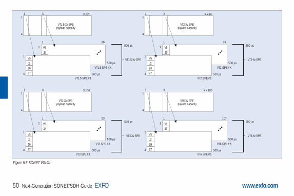
www.exfo.com50 Next-Generation SONET/SDH Guide EXFO
V5
J2
Z6
Z7
1
1
V5
J2
Z6
Z7
1 X X x 25
VT1.5-Xv SPEpayload capacity
1
4
1
4
26
VT1.5 SPE #1
VT1.5 SPE #X
VT1.5-Xv SPE
500 µs
500 µs
500 µs
V5
J2
Z6
Z7
1
1
V5
J2
Z6
Z7
1 X X x 52
VT3-Xv SPEpayload capacity
1
4
1
4
53
VT3 SPE #1
VT3 SPE #X
VT3-Xv SPE
500 µs
500 µs
500 µs
V5
J2
Z6
Z7
1
1
V5
J2
Z6
Z7
1 X X x 34
VT2-Xv SPEpayload capacity
1
4
1
4
36
VT2 SPE #1
VT2 SPE #X
VT2-Xv SPE
500 µs
500 µs
500 µs
V5
J2
Z6
Z7
1
1
V5
J2
Z6
Z7
1 X X x 106
VT6-Xv SPEpayload capacity
1
4
1
4
107
VT6 SPE #1
VT6 SPE #X
VT6-Xv SPE
500 µs
500 µs
500 µs
Figure 5.5 SONET VTn-Xv
Guide NEXT-GEN.3-ang: Guide Ethernet.1AN 5/7/07 11:31 AM Page 50

Next-Generation SONET/SDH Guide EXFO 51www.exfo.com
To define its multiframe, LO VCAT uses a similar concept as that described above for HO VCAT groups. For the LO VCGs, low-order path overheadbytes Z7 (bit 2) [SONET] and K4 (bit 2) [SDH] are used to support the multiframe structure and specify the MFI and SQ values.
5.2.2 LO VCAT Multiframe and Sequence Indicator (SQ)
Bit 2 of Z7/K4 is used to convey LO VCAT information. It forms a serial string of 32 bits (over 32 four-frame multiframes), as defined in ANSI T1.105 [19] and ITU G.707 (see Figure 5.7). This string is repeated every 16 ms (32 bits x 4 x 125 s/bit) or every 128 frames. This processis repeated until the frame count reaches 32. This means that the total number of frames for a full cycle is 128 frames x 32 = 4096 frames.
The following fields define the frame:
• Frame count is contained in Bits 1 to 5 of the 32-bit string.
• The sequence indicator is contained in Bits 6 to 11 of the 32-bit string.
• The remaining bits (12 to 32) are reserved for other applications. These bits must be set to 0 and must be ignored by the receiver when VCAT is activated without LCAS.
V5
J2
11
V5
J2
N2
K4
1 X X x 34
C-12-Xc
1
4
11
4
35
VC-12 #1
VC-12 #X
VC-12-Xv
500 µs
500 µs
500 µs
N2
K4
V5
J2
11
V5
J2
N2
K4
1 X X x 106
C-2-Xc
1
4
11
4
107
VC-2 #1
VC-2 #X
VC-2-Xv
500 µs
500 µs
500 µs
N2
K4
V5
J2
11
V5
J2
N2
K4
1 X X x 25
C-11-Xc
1
4
11
4
26
VC-11 #1
VC-11 #X
VC-11-Xv
500 µs
500 µs
500 µs
N2
K4
Figure 5.6 SDH VC-n-Xv
Guide NEXT-GEN.3-ang: Guide Ethernet.1AN 5/7/07 11:31 AM Page 51

52 Next-Generation SONET/SDH Guide EXFO www.exfo.com
The entire cycle is provided by a frame count that is divided into 32 steps of 16 ms, yielding a total of 512 ms for the length of the multiframe.
The sequence indicator identifies the sequence or the order in which the individual VTn or VC-n of the VTn-Xv or VC-n-Xv is assembled to form thecontiguous container VTn-Xc or VC-n-Xc, as displayed in Figure 5.5 and Figure 5.6, respectively. Each member of the VCG has a fixed uniquesequence indicator in the range of 0 to (X–1). The sequence indicator for the first VTn or VC-n within the VCG is 0, while the second VTn or VC-n uses sequence indicator 1, and so on up to the last member (SQ = X-1).
In the event that the terminating equipment is unable to recover the frame or the sequence, or if there is too much differential delay, the system isequipped to generate alarms to the management system to highlight these conditions.
5.3 VCAT Differential DelayVCAT payload can be split and sent along different paths through the network. Therefore, it is entirely possible that these different paths will notcover the same distance and may contain a different number of network elements along their route. This would mean that members of the VCGdo not reach the termination point (end PTE) at the same time. In order for the terminating equipment to reassemble the payload, it must be ableto compensate for the difference in payload arrival times. This arrival time difference is known as the differential delay.
Differential delay is the relative arrival time measurement between the members of a VCG. This means that in a next-generation SONET/SDHnetwork, buffering is required at the terminating end of a VCG connection in order to realign the data stream. For high-order VCAT paths, the differential delay is measured by examining the multiframe indicator (MFI) present in the path overhead of each VCG member. For low-orderVCAT paths, the frame-count information is used to determine differential delay.
1 2 3 4 5 6 7 8 9 10 11 12 13 14 15 16 17 18 19 20 21 22 23 24 25 26 27 28 29 30 31 32Bit Number
Frame Count Sequence Indicator Reserved BitsCTRL Packet
Z7/K2Structure
Figure 5.7 LOP Z7/K4 Bit 2 Multiframe Structure
Guide NEXT-GEN.3-ang: Guide Ethernet.1AN 5/7/07 11:31 AM Page 52

Next-Generation SONET/SDH Guide EXFO 53www.exfo.com
The VCAT standards define the maximum differential delay between members of a VCG to be 256 ms. However, given the amount of bufferingrequired at the terminating points, it is often the case that next-generation SONET/SDH PTEs support less than this maximum, hence making VCATtesting an important consideration when verifying the performance of these network elements.
5.4 VCAT SummaryIn short, virtual concatenation provides a means of creating “right-sized” SONET/SDH containers that better match the bandwidth requirements ofdata client signals such as Ethernet and Fibre Channel. In addition, the flexible nature of VCAT allows service providers to create these right-sizedpipes from the unused bandwidth/timeslots present in their network.
All the intelligence needed to create and handle a virtual concatenation is located at the end points of the connections (i.e., at the PTEs). The receiving end-point PTE is responsible for reassembling the original byte stream. This allows SONET/SDH channels to be routed independentlythrough the network without requiring any acknowledgement of the virtual concatenation. In this manner, virtually concatenated channels may bedeployed on the existing SONET/SDH network with a simple end-point upgrade.
Guide NEXT-GEN.3-ang: Guide Ethernet.1AN 5/7/07 11:31 AM Page 53

Link-Capacity Adjustment Scheme (LCAS)
Guide NEXT-GEN.3-ang: Guide Ethernet.1AN 5/7/07 11:31 AM Page 54

6. Link-Capacity Adjustment Scheme (LCAS)LCAS, as defined per ITU-T recommendation G.7042, is a complementary technology to virtual concatenation. LCAS allows for the dynamicchanging of the size of a VCAT group. To do so, signaling messages are exchanged within the same SONET/SDH overhead bytes used for VCAT(H4 for HO VCAT and Z7/K4 for LO VCAT) between the source PTE to the end-point PTE in order to change the number of tributaries being usedby a virtually concatenated group (VCG). For example, the number of tributaries can be increased or decreased in response to an identified changein service-bandwidth requirement, or in response to a fault condition of an existing VCG member.
LCAS works by ensuring synchronization betweenthe sender (PTE), referred to as the source node, andreceiver (PTE), referred to as the sink node, duringthe increase/decrease of the size of a virtuallyconcatenated circuit, in such a way that it doesn’tinterfere with the underlying client data service.Should failures occur on an individual member of agroup, the size of the group can be reducedtemporarily, instead of taking the entire group out ofservice (which would be the case if LCAS were notenabled – the entire VCG would be declared as"failed” in the event of a failure of one VCGmembers). With LCAS, once the defect is repaired,the group size can be restored to full bandwidthwithout affecting the underlying service.
Next-Generation SONET/SDH Guide EXFO 55www.exfo.com
ClientSignal
VT1.5-4v
Hitless increase from VT1.5-4v toVT1.5-5v using LCAS protocol
Existing VCG memberAdded VCG member
Figure 6.1 Increasing VCG Size Using LCAS
Guide NEXT-GEN.3-ang: Guide Ethernet.1AN 5/7/07 11:31 AM Page 55
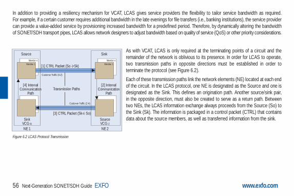
56 Next-Generation SONET/SDH Guide EXFO www.exfo.com
In addition to providing a resiliency mechanism for VCAT, LCAS gives service providers the flexibility to tailor service bandwidth as required. For example, if a certain customer requires additional bandwidth in the late evenings for file transfers (i.e., banking institutions), the service providercan provide a value-added service by provisioning increased bandwidth for a predefined period. Therefore, by dynamically altering the bandwidthof SONET/SDH transport pipes, LCAS allows network designers to adjust bandwidth based on quality of service (QoS) or other priority considerations.
As with VCAT, LCAS is only required at the terminating points of a circuit and theremainder of the network is oblivious to its presence. In order for LCAS to operate,two transmission paths in opposite directions must be established in order toterminate the protocol (see Figure 6.2).
Each of these transmission paths link the network elements (NE) located at each endof the circuit. In the LCAS protocol, one NE is designated as the Source and one isdesignated as the Sink. This defines an origination path. Another source/sink pair, in the opposite direction, must also be created to serve as a return path. Betweentwo NEs, the LCAS information exchange always proceeds from the Source (So) tothe Sink (Sk). The information is packaged in a control packet (CTRL) that containsdata about the source members, as well as transferred information from the sink.
SourceMember n
Member 1
[4] InternalCommunication
Path
SinkVCG-BNE 1
SinkMember n
Member 1
[2] InternalCommunication
Path
SourceVCG-ZNE 2
[1] CTRL Packet (So - Sk)
[3] CTRL Packet (Sk - So)
Customer Traffic (A-Z)
Customer Traffic (Z-A)
Transmission Paths
Figure 6.2 LCAS Protocol Transmission
Guide NEXT-GEN.3-ang: Guide Ethernet.1AN 5/7/07 11:31 AM Page 56

Next-Generation SONET/SDH Guide EXFO 57www.exfo.com
Figure 6.2 represents a NE1 source that sends a CTRL packet [1] to the NE2 sink. The NE2 sink receives the CTRL packet and processes it. Inaddition to the result of this processing, the detected status of its own members is shared with the NE2 source via an internal communication path [2].At this point, using the return path, the NE2 source sends its own CTRL packet [3], which contains its own CTRL information as well as the NE2sink information. The LCAS protocol loop is closed when the NE1 sink shares the information that is received from the NE2 sink to the NE1 sourcevia the internal communication path [4]. This information transfer is also done in the same manner if the described scenario originates from theNE2 Source.
6.1 LCAS Control PacketsBelow is the list of ITU-defined control packets for both directions of an LCAS signaling link.
FIXED Indicates that this end uses fixed bandwidth (non-LCAS mode).
ADD Indicates that this member is about to be added to the group.
NORM Indicates that there is no change; steady state.
IDLE Indicates that this member is not part of the group or about to be removed.
EOS Indicates the end of sequence; normal transmission.
DNU Means do not use payload; indicates that the Sk side reported FAIL status.
Table 6.1 – ITU-Defined LCAS Control Packets
Guide NEXT-GEN.3-ang: Guide Ethernet.1AN 5/7/07 11:31 AM Page 57

58 Next-Generation SONET/SDH Guide EXFO www.exfo.com
6.2 LCAS Example 1: Capacity IncreaseThe bandwidth of a VCG can be increased through the LCAS’ ability to enable in-service addition of one or more members in a VCG. This bandwidth increase is typically controlled by the user via a network management system. The steps detailed in Figure 6.3 are used to performthis bandwidth increase.
Table 6.2 – Sink to Source: Depicted as Message [3] in Figure 6.2.
Table 6.3 – Common LCAS Messages for Path [1] and [3].
MST Information from Sk to So about the status of all members of the same VCG. It reports the member status from Sk to Sowith two states: OK or FAIL (1 status bit per member). OK = 0, FAIL = 1. Since each control packet contains only a limited numberof bits for communicating the MST field, this information is spread across multiple control packets; i.e., an MST multiframe.
RS-Ack When a renumbering of the sequence numbers of the members sending in CTRL field NORM, DNU, EOS, or when achange of the number of these members is detected at the Sk, a notification to the So per VCG has to be performed bytoggling (i.e., change from 0 to 1 or from 1 to 0) the RS-Ack bit.
Both (Common)
CRC-8 To simplify the variation of the changes in the virtual concatenation overhead, a CRC is used to protect each control packet. The CRC check is performed on every control packet after it has been received, and the content is rejected if the test fails. If the control packet passes the CRC test, then its content is used immediately.
Guide NEXT-GEN.3-ang: Guide Ethernet.1AN 5/7/07 11:31 AM Page 58

Next-Generation SONET/SDH Guide EXFO 59www.exfo.com
STS-1 (1,1)/AU-3 (1,1), SQ = 0, GID = a, CTRL = NORM
STS-1 (1,3)/AU-3 (1,3), SQ = 1, GID = a, CTRL = NORM
STS-1 (2,1)/AU-3 (2,1), SQ = 2, GID = a, CTRL = NORM
STS-1 (2,3)/AU-3 (2,3), SQ = 3, GID = a, CTRL = EOS
STS-1 (3,2)/AU-3 (3.2), SQ = 255, GID = a, CTRL = IDLE
ClientSignal
STS-1 (1,1)/AU-3 (1,1), SQ = 0, GID = a, CTRL = NORM
STS-1 (1,3)/AU-3 (1,3), SQ = 1, GID = a, CTRL = NORM
STS-1 (2,1)/AU-3 (2,1), SQ = 2, GID = a, CTRL = NORM
STS-1 (2,3)/AU-3 (2,3), SQ = 3, GID = a, CTRL = NORM
STS-1 (3,2)/AU-3 (3.2), SQ = 4, GID = a, CTRL = EOS
ClientSignal
STS-1 (1,1)/AU-3 (1,1), SQ = 0, GID = a, CTRL = NORM
STS-1 (1,3)/AU-3 (1,3), SQ = 1, GID = a, CTRL = NORM
STS-1 (2,1)/AU-3 (2,1), SQ = 2, GID = a, CTRL = NORM
STS-1 (2,3)/AU-3 (2,3), SQ = 3, GID = a, CTRL = EOS
STS-1 (3,2)/AU-3 (3.2), SQ = 4, GID = a, CTRL = ADD
ClientSignal
STS-1 (1,1)/AU-3 (1,1), SQ = 0, GID = a, CTRL = NORM
STS-1 (1,3)/AU-3 (1,3), SQ = 1, GID = a, CTRL = NORM
STS-1 (2,1)/AU-3 (2,1), SQ = 2, GID = a, CTRL = NORM
STS-1 (2,3)/AU-3 (2,3), SQ = 3, GID = a, CTRL = NORM
STS-1 (3,2)/AU-3 (3.2), SQ = 4, GID = a, CTRL = EOS
ClientSignal
Step 1 Step 3
Step 2 Step 4
LCAS Bandwidth Increase, OC-12/STM-4 exemple
Figure 6.3 Bandwidth Increase
Guide NEXT-GEN.3-ang: Guide Ethernet.1AN 5/7/07 11:31 AM Page 59

60 Next-Generation SONET/SDH Guide EXFO www.exfo.com
• Step 0: A member needs to be added to an existing VCG that is LCAS-enabled. In this example, the member to add is STS-1[3,2], or AU-3[3,2].
• Step 1: The management system is used to configure the member at the source and sink NE.
- The source automatically sets the SQ to 255, the highest possible number at the source and the sink NE. (based on VCAT standard)
- The sink sets the MST to FAIL.
• Step 2: The management system configures LCAS state machine to ADD.
- In the source, the SQ is automatically set to 4, the next highest SQ available, and the CTRL is set to ADD.
- The source waits for the sink to send MST = OK for the member with SQ = 4. While waiting for this MST = OK message, the source willcontinue to send a CTRL = ADD for this member.
• Step 3: The source receives MST = OK for member SQ = 4.
- The source sends EOS to the last member added, indicating to the sink that this is indeed the last member of the VCG, and sends NORMfor the previously defined last member (of course, this is assuming that no fault occurs on this member during that time).
- The new member begins to carry traffic in the first frame after the last byte in the frame transporting CTRL = NORM/EOS change.
Note: If multiple members were added, all members would be set to NORM, except for the last one in the sequence, which would be set to EOS.
• Step 4: The sink detects the transition from ADD to NORM/EOS for the new member
- The sink sends RS-ACK to the source to acknowledge the new sequence.
- The sink sets the MST to be consistent with the new sequence.
- Following the proper delay compensation, the source is allowed to evaluate the new member status when it receives the RS-Ack.
Guide NEXT-GEN.3-ang: Guide Ethernet.1AN 5/7/07 11:31 AM Page 60

www.exfo.com Next-Generation SONET/SDH Guide EXFO 61
6.3 LCAS Example 2: Capacity ReductionThere are two methods for LCAS to support thecapacity reduction of a VCG: automatictemporary removal of one or more member(s)due to a network fault, or manual deprovisioningof one or more member(s) to permanentlyreduce the bandwidth supported by the VCG.
Automatic Temporary Removal
The temporary removal of a member isautomatically handled by the LCASprotocol, as presented in Figure 6.4 andassociated steps. This capability providesVCAT with its resiliency mechanism as thesize of the group can be reducedtemporarily, instead of taking the entiregroup out of service (which would be thecase for VCGs without LCAS enabled).Once the defect is repaired, the group sizecan be restored to full bandwidth withoutaffecting the underlying service.
STS-1 (1,1)/AU-3 (1,1), SQ = 0, GID = a, CTRL = NORM
STS-1 (1,3)/AU-3 (1,3), SQ = 1, GID = a, CTRL = NORM
STS-1 (2,1)/AU-3 (2,1), SQ = 2, GID = a, CTRL = NORM
STS-1 (2,3)/AU-3 (2,3), SQ = 3, GID = a, CTRL = NORM
STS-1 (3,2)/AU-3 (3,2), SQ = 4, GID = a, CTRL = EOS
ClientSignal
STS-1 (1,1)/AU-3 (1,1), SQ = 0, GID = a, CTRL = NORM
STS-1 (1,3)/AU-3 (1,3), SQ = 1, GID = a, CTRL = NORM
STS-1 (2,1)/AU-3 (2,1), SQ = 2, GID = a, CTRL = NORM
STS-1 (2,3)/AU-3 (2,3), SQ = 3, GID = a, CTRL = EOS
STS-1 (3,2)/AU-3 (3.2), SQ = 4, GID = a, CTRL = DNU
ClientSignal
STS-1 (1,1)/AU-3 (1,1), SQ = 0, GID = a, CTRL = NORM
STS-1 (1,3)/AU-3 (1,3), SQ = 1, GID = a, CTRL = NORM
STS-1 (2,1)/AU-3 (2,1), SQ = 2, GID = a, CTRL = NORM
STS-1 (2,3)/AU-3 (2,3), SQ = 3, GID = a, CTRL = EOS
STS-1 (3,2)/AU-3 (3.2), SQ = 4, GID = a, CTRL = DNU
ClientSignal
STS-1 (1,1)/AU-3 (1,1), SQ = 0, GID = a, CTRL = NORM
STS-1 (1,3)/AU-3 (1,3), SQ = 1, GID = a, CTRL = NORM
STS-1 (2,1)/AU-3 (2,1), SQ = 2, GID = a, CTRL = NORM
STS-1 (2,3)/AU-3 (2,3), SQ = 3, GID = a, CTRL = NORM
STS-1 (3,2)/AU-3 (3.2), SQ = 4, GID = a, CTRL = EOS
ClientSignal
Step 1 Step 1
Step 2 Step 2
LCAS Bandwidth Reduction (Temporary Removal) , OC-12/STM-4 example
Temporary Removal Restoration
FAULT CLEAR
FAULT
Figure 6.4 Bandwidth Reduction (Temporary Removal)
Guide NEXT-GEN.3-ang: Guide Ethernet.1AN 5/7/07 11:31 AM Page 61
62 Next-Generation SONET/SDH Guide EXFO www.exfo.com
Temporary Removal
• Step 1: A fault is detected at the sink for a member (i.e., STS-1 [3,2], AU-3 [3,2]).
- At the sink, the fault can take the form of a member status unavailable (MSU) or transport signal degraded (TSD). An MSU would be generated by an AIS or LOP for example. The TSD would be errors detected on the path crossing a certain threshold.
- If the source of these members was sending a NORM or EOS in this condition, the sink would start sending a MST = FAIL for the specific SQ.
- Typically, a hold-off timer can be configured to delay the reporting of MST = FAIL to avoid transient error occurrences.
• Step 2: Member removal
- At the sink NE and upon the detection of the MSU, the member would be removed immediately. However, if the failure is related to a TSD, the member would be removed only when the sink NE receives the DNU from the source NE.
- At the originating source NE a detection of the MST = FAIL will trigger the replacement of the NORM/EOS by a DNU condition. Within the remaining active member, the member with the highest SQ will send EOS in the CTRL field.
Restoration
• Step 1: Fault clears
- When the defect that caused the temporary removal is terminated and is detected at the sink, the sink will start sending a MST = OKfor that member.
- Upon detection of the MST = OK, the source will either replace the DNU condition by an NORM condition, or replace the DNU condition with an EOS condition, and the preceding member, which was sending CTRL code EOS, will send NORM in the CTRL field.
• Step 2: Payload activation
- The final step after recovering from a temporary removal is to start using the payload area of that member again. The first containerframe to contain payload data for the member is the container frame immediately following the container frame that contained the lastbit(s) of the control packet containing the first CTRL code (NORM or EOS) in the CTRL field for that member.
Guide NEXT-GEN.3-ang: Guide Ethernet.1AN 5/7/07 11:31 AM Page 62

Next-Generation SONET/SDH Guide EXFO 63www.exfo.com
Member Permanent Removal
The bandwidth of a VCG can be permanentlyreduced using the LCAS’ ability to enable in-service removal of one or more member(s) fromthe VCG. This bandwidth reduction is controlledby the user via a network management system.The steps detailed in Figure 6.5 are used toperform this reduction of bandwidth.
Note: The removal of a member must be doneat the source in order for the operation to behitless. If it is done at the sink first, the traffic willbe corrupted from the time the member isremoved (sink generates MST = FAIL) and thesink receives a DNU generated from the source.
STS-1 (1,1)/AU-3 (1,1), SQ = 0, GID = a, CTRL = NORM
STS-1 (1,3)/AU-3 (1,3), SQ = 1, GID = a, CTRL = NORM
STS-1 (2,1)/AU-3 (2,1), SQ = 2, GID = a, CTRL = NORM
STS-1 (2,3)/AU-3 (2,3), SQ = 3, GID = a, CTRL = NORM
STS-1 (3,2)/AU-3 (3,2), SQ = 4, GID = a, CTRL = EOS
ClientSignal
STS-1 (1,1)/AU-3 (1,1), SQ = 0, GID = a, CTRL = NORM
STS-1 (1,3)/AU-3 (1,3), SQ = 1, GID = a, CTRL = NORM
STS-1 (2,1)/AU-3 (2,1), SQ = 2, GID = a, CTRL = NORM
STS-1 (2,3)/AU-3 (2,3), SQ = 3, GID = a, CTRL = EOS
STS-1 (3,2)/AU-3 (3.2), SQ = 255, GID = a, CTRL = IDLE
ClientSignal
Step 1 Step 2/Step 3/Step 4
LCAS Bandwidth Reduction (Permanent Removal) , OC-12/STM-4 example
DELETE
Figure 6.5 Bandwidth Reduction (Permanent Removal)
Guide NEXT-GEN.3-ang: Guide Ethernet.1AN 5/7/07 11:31 AM Page 63
• Step 1: One or more member(s) need to be removed from an existing VCG. In this example, again we are using STS-1 [3,2], AU-3 [3,2].
- This operation must be initiated from a management system.
• Step 2: At the source, the management system deletes the member from the VCG.
- The CTRL field is set to IDLE, while the SQ is automatically set to 255.
- Depending on which member is deleted in the VCG, the SQ for the remaining members may be renumbered. For example, if the memberthat is removed is the highest number in the VCG, the members’ SQs will not be renumbered. However, if a member other than the lastis removed, then SQ renumbering will occur in line with the new order.
- The source will send a new CTRL word (changed from NORM to EOS) for the last member of the VCG.
• Step 3: At the sink, the CTRL word and SQ are received.
- When the CTRL = IDLE signal is detected, the MST for the member is set to FAIL and the RS-Ack is toggled.
• Step 4: At the sink, the management system deletes the member from the VCG.
64 Next-Generation SONET/SDH Guide EXFO www.exfo.com
Guide NEXT-GEN.3-ang: Guide Ethernet.1AN 5/7/07 11:31 AM Page 64

Next-Generation SONET/SDH: Testing Implications
Guide NEXT-GEN.3-ang: Guide Ethernet.1AN 5/7/07 11:31 AM Page 65

66 Next-Generation SONET/SDH Guide EXFO www.exfo.com
7. Next-Generation SONET/SDH: Testing ImplicationsWith these new technologies comes a new terminology for next-generation SONET/SDH-capable add-drop multiplexers (ADMs). ADMssupporting GFP, VCAT, and LCAS are known in the industry as multiservice provisioning platforms (MSPPs). By deploying MSPPs in their network,a service provider can now deliver packet-based transport services using their existing SONET/SDH infrastructure. As mentioned in Chapters 4, 5 and 6,the intelligence needed to support GFP, VCAT, and LCAS is located at the endpoints of the network; therefore, MSPPs need only be deployed atthe edge of the transport network, where services are created.
MSSPs offer obvious advantages to service providers as they help maximize the usage of the current install base with minimal capital expenditurewhile providing a new revenue stream to fuel growth for the coming years. However, with these new technologies come new deploymentchallenges. GFP, VCAT and LCAS add another layer of complexity to accommodate the transport of different data services. In many cases, thesenext-generation functionalities are delivered as enhancements to existing SONET/SDH ADMs. Nevertheless, for a service provider, whether it isdelivered by new network elements or enhancements to existing ADMs, this additional layer needs to be fully tested.
In this section, we will briefly discuss testing scenarios that must be considered for next-generation SONET/SDH networking to determine theproper operation of these MSPPs and, consequently, the proper operation of the next-generation data services being offered.
7.1 GFP Test Scenarios
Conformance Testing
The purpose of these tests is to verify MSPP conformance to GFP ITU-T G.7041 specifications. As we have seen, GFP is responsible formapping a wide range of clients (Ethernet, ESCON, FICON, etc.) onto the transport layer. Because of this, the GFP frame must have formatsand contents that match the payload type. Therefore, next-generation test equipment is used for the following purposes:
Guide NEXT-GEN.3-ang: Guide Ethernet.1AN 5/7/07 11:31 AM Page 66
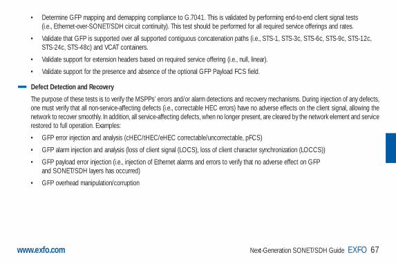
Next-Generation SONET/SDH Guide EXFO 67www.exfo.com
• Determine GFP mapping and demapping compliance to G.7041. This is validated by performing end-to-end client signal tests (i.e., Ethernet-over-SONET/SDH circuit continuity). This test should be performed for all required service offerings and rates.
• Validate that GFP is supported over all supported contiguous concatenation paths (i.e., STS-1, STS-3c, STS-6c, STS-9c, STS-12c, STS-24c, STS-48c) and VCAT containers.
• Validate support for extension headers based on required service offering (i.e., null, linear).
• Validate support for the presence and absence of the optional GFP Payload FCS field.
Defect Detection and Recovery
The purpose of these tests is to verify the MSPPs’ errors and/or alarm detections and recovery mechanisms. During injection of any defects,one must verify that all non-service-affecting defects (i.e., correctable HEC errors) have no adverse effects on the client signal, allowing thenetwork to recover smoothly. In addition, all service-affecting defects, when no longer present, are cleared by the network element and servicerestored to full operation. Examples:
• GFP error injection and analysis (cHEC/tHEC/eHEC correctable/uncorrectable, pFCS)
• GFP alarm injection and analysis (loss of client signal (LOCS), loss of client character synchronization (LOCCS))
• GFP payload error injection (i.e., injection of Ethernet alarms and errors to verify that no adverse effect on GFP and SONET/SDH layers has occurred)
• GFP overhead manipulation/corruption
Guide NEXT-GEN.3-ang: Guide Ethernet.1AN 5/7/07 11:31 AM Page 67

68 Next-Generation SONET/SDH Guide EXFO www.exfo.com
Performance Characterization
The purpose of these tests is to verify theMSPPs’ GFP mapping and demappingperformance and efficiency. For example, giventhe fact that GFP-F frame sizes, and hencemapping functions, are directly related to theclient signal frame size, it is important to verifythat the network elements present GFPmapper efficiency in the following areas:
• GFP payload pattern generation (use aninternal GFP PRBS pattern generator tovary the GFP payload information field from0 to 65,535 – X octets, where X is the sizeof the payload header (including theextension header, if present) and thepayload FCS field (if present).
• Verify the GFP mapping efficiency per client signal frame size; i.e., Ethernet packet sweep from minimum to maximum supported size (jumbo frame) of the client signal.
• GFP multiservice performance. For example, many GFP mapper interface cards support quality-of-service functions such as the ability toperform policing, scheduling, and classifying per client signal and service. Test equipment can be used to emulate this multiserviceenvironment using multiple stream (i.e., Ethernet) each with their own transmission rate and QoS settings (i.e., IP Tos, IP DiffServ, Ethernet802.1q priority tagging).
OC-n/STM-n Ethernet loop or connected to an Ethernet test module
Tests: • GFP mapping and demapping based on ITU-T G.7041, including support for extension headers (linear, ring) • GFP mapping with variable rate Ethernet signal inputs (i.e. packet sweeps) • GFP multiservice performance (mapper’s ability to perform policing, scheduling, and classifying per client signal and service) • GFP error injection and analysis (cHEC/tHEC/eHEC correctable/uncorrectable, pFCS) • GFP alarm injection and analysis: (LOCS, LOCCS) • GFP payload (i.e. Ethernet) error injection • GFP overhead manipulation • GFP optional payload FCS validation • GFP mapping efficiency (per client signal frame size)Purpose: • Verify NE’s conformance to GFP ITU-T specifications • Verify NE’s supported GFP functionaility – functional validation • Verify NE’s GFP mapper performance (i.e. characterization)
MSSP
Figure 7.1 GFP Test Scenarios
Guide NEXT-GEN.3-ang: Guide Ethernet.1AN 5/7/07 11:31 AM Page 68

Next-Generation SONET/SDH Guide EXFO 69www.exfo.com
7.2 VCAT Test Scenarios
Conformance Testing
The purpose of conformance testing is to verify that network elements receive and transmit in conformance to VCAT containers defined in ITU-T G.707 specifications.
As we have seen, virtual concatenation is a very efficient way to transmit data services over SONET/SDH networks. We know that severalcontainers are formed into a common payload (the virtual concatenation group or VCG). The tests described below check that setting up,expansion and reduction of a VCG has been accomplished without errors.
• HO VCAT container support (all valid combinations) – typically used for 100BaseT and Gigabit Ethernet
• LO VCAT container support (all valid combinations) – typically used for sub-rate 10/100BaseT, 10BaseT, and 100BaseT Ethernet services
• Validate the maximum number of VCG members supported (for all valid HO and LO container types)
Table 7.1 – Common HO and LO VCAT Container Types
HO PATH LO PATHSONET SDH SONET SDH
STS-1 VC-3 VT1.5 TU-11
STS-3c VC-4 VT2 TU-12
VT6 TU-3
TU-2
Guide NEXT-GEN.3-ang: Guide Ethernet.1AN 5/7/07 11:31 AM Page 69

70 Next-Generation SONET/SDH Guide EXFO www.exfo.com
Defect Detection and Recovery The purpose of these tests is to verify the network elements’ error and/or alarm detection and recovery mechanisms. During injection of anydefects, one must verify that defects are properly identified by the network element and, when they are no longer present, that they arecleared by the network element and service restored to full operation:
• VCAT alarm injection and analysis (LOM, OOM1, OOM2, SQM, LOA) - single-member alarm injection- multiple-member alarm injection
• For HO VCAT, high-order path error insertion and analysis; e.g., REI-P, B3 errors, etc.- single-member alarm injection- multiple-member alarm injection
• For LO VCAT, low-order path error insertion and analysis; e.g., REI-P, B3 errors, etc.- single-member alarm injection- multiple-member alarm injection
Note: These tests should be performed for both non-LCAS and LCAS-configured VCGs.
Guide NEXT-GEN.3-ang: Guide Ethernet.1AN 5/7/07 11:31 AM Page 70

Next-Generation SONET/SDH Guide EXFO 71www.exfo.com
Differential Delay Injection and Analysis
As described above, the ITU specification for VCAT statesthat a differential delay of up to 256 ms must be supportedon network elements in order for them to compensate for thedelay between arrival times of individual VCG members totheir destination (sink mode). However, given the amount ofbuffering required at the terminating points, it is often thecase that next-generation SONET/SDH PTEs support lessthan this maximum.
The purpose of differential delay injection tests and analyses isto verify the performance of these next-generation networkelements against the maximum differential delay that theysupport. Test equipment must then support both the injectionand analysis of differential delay per VCG member (both HOand LO VCAT). The test equipment should support a delay ofup to 256 ms, to cover for the maximum, and support a delayinjection resolution of at least 125 µs for HO, and 500 µs for LO.
OC-n/STM-n EthernetLoop
Tests:• HO VCAT container support (all valid combinations)• LO VCAT container support (all valid combinations)• VCAT alarm injection and analysis (LOM, OOM1, OOM2, SQM, LOA)• VCAT error insertion and analysis (all support SONET/SDH path errors – e.g. REI-P, B3, etc.)• VCAT error and alarm injection: single and multiple member injections• Sequence indicator manipulation and processing• Differential delay injection and analysis – per member (up to 256 ms) Purpose: • Verify NE’s conformance to LO and HO VCAT containers specified in ITU-T G.707• Verify NE’s performance with differential delay injection values specified in ITU-T G.707• Verify NE’s performance in the event of single and multiple alarm/errors events
MSSP
Figure 7.2 VCAT Test Scenarios
Guide NEXT-GEN.3-ang: Guide Ethernet.1AN 5/7/07 11:31 AM Page 71

72 Next-Generation SONET/SDH Guide EXFO www.exfo.com
7.3 LCAS Test Scenarios
Conformance Testing
The purpose of LCAS conformance testing is to verify that the MSPPs comply with the LCAS signaling mechanism defined in the ITU-T G.7042 specifications.
As we have seen, LCAS works by ensuring synchronization between the sender PTE (source) and receiver PTE (sink) during theincrease/decrease in size of a virtually concatenated circuit, in such a way that it doesn’t interfere with the underlying data service. Thissynchronization ensures that, in the event of VCG member failure, the size of the VCG can be reduced temporarily, instead of taking the entiregroup out of service (which would be the case if LCAS were not enabled). With LCAS, once the defect is repaired, the group size can berestored to full bandwidth, without affecting the underlying service. In addition to providing a resiliency mechanism for VCAT, LCAS gives usersthe flexibility to add and remove members to a VCG as needed.
LCAS testing should therefore be focused on ensuring that the following functions are supported on the network element:
• Manual addition and removal of VCG members (tested on all supported HO VCAT containers). Separate tests should be performed for addition and removal of first, last, and middle members. Multiple-member addition and removal should also be performed.
• Manual addition and removal of VCG members (tested on all supported LO VCAT containers). Separate tests should be performed for addition and removal of first, last, and middle members. Multiple-member addition and removal should also be performed.
• Behavior (detection and recovery) in the event of a failure on a VCG member (tested on all supported HO VCAT containers). See the VCAT Defect Detection and Recovery section on page 70 for a list of errors and alarms that should be used.
• Behavior (detection and recovery) in the event of a failure on a VCG member (tested on all supported HO VCAT containers). See the VCAT Defect Detection and Recovery section on page 70 for a list of errors and alarms that should be used.
Guide NEXT-GEN.3-ang: Guide Ethernet.1AN 5/7/07 11:31 AM Page 72

Next-Generation SONET/SDH Guide EXFO 73www.exfo.com
OC-n/STM-n
Tests:• Generate LCAS messages as source or sink either manually or automatically• Analyze LCAS messages/states and alarms• Validate LCAS functions (member adds, removes, failure recovery, etc.) for both HO and LO VCAT containersPurpose: • Verify NE’s conformance to LCAS as per ITU-T specification• Verify multivendor LCAS interoperability
MSSPMSSPMSSP
Figure 7.3 LCAS Test Scenarios
Guide NEXT-GEN.3-ang: Guide Ethernet.1AN 5/7/07 11:31 AM Page 73

74 Next-Generation SONET/SDH Guide EXFO www.exfo.com
7.4 Continuity and Performance Testing Prior to wide-scale deployment in live networks, next-generation services to be offered (10BaseT, 100BaseT, 1000BaseT, GigE, etc.) must beemulated and tested. In addition, given the fact that multivendor networks are now commonplace and that these technologies are still in theirearly stages, it is important that proper vendor interoperability tests are performed so as to mitigate risks prior to deployment.
The purpose of these tests is to verify the continuity and performance for all offered services. This is done by creating a test environment thatclosely matches live network topology and by using a next-generation test unit that supports both client signal interfaces and GFP, VCAT, andLCAS technologies. Continuity between source and sink nodes must be checked, in addition to verifying the maximum number of client signalsthat can be supported in this configuration, to ensure scalability of the network elements prior to wide-scale deployments.
7.5 Service Turn-Up TestingWith next-generation networks, field techniciansmust be equipped with versatile test equipment thatcan provide the necessary functions to turn up bothTDM circuits and next-generation packet-basedservices such as Ethernet and Fibre Channel.Service providers and equipment vendors cannotafford to supply each field technician with amultitude of disparate test equipment to performtheir daily duties. Their test units must be capable ofsupporting legacy TDM (electrical and optical) andnext-generation packet-based circuit turn-ups, as wellas common client signal test interfaces such as10/100/1000M Ethernet and Fibre Channel.
Tests:• Generate 10/100/1000M or Gigabit Ethernet traffic through DUTs• Generate and analysis Ethernet errors and alarms• Perform Through-Mode analysis of GFP frames, including alarms and errors• Verify mapping efficiency of data mapping (GFP) interface cards (using variable payload rate inputs)• Perform Through-Mode analysis of VCAT group used as container to the GFP-mapped Ethernet traffic (including differential delay analysis)Purpose: • End-to-end service validation (including multiservice service delivery – e.g. voice, video, data).• Multivendor MSPP interoperability validation
MSSP MSSP
SONET/SDH w/ GFPEthernet traffic
Figure 7.4 Next-Generation Service Continuity and Performance Testing
Guide NEXT-GEN.3-ang: Guide Ethernet.1AN 5/7/07 11:31 AM Page 74

Next-Generation SONET/SDH Guide EXFO 75www.exfo.com
Before going into a detailed description of the tests required to qualify TDM and next-generation circuits, it is important to understand that propertesting of any network — whether SONET or Ethernet, fiber or copper — should start from the bottom; that is, at the physical-layer level.
A comprehensive suite of physical-layer tests should be completed prior to any testing in the digital domain. Although we will not be addressingthese tests herein, it is essential to know what they are:
• Power loss
• Return loss
• Dispersion (for high-speed optical systems)
• Media profile (splice loss, attenuation, reflectance, etc)
Correctly performing these tests will ensure that future testing is not hindered by any problems in the underlying physical media, preventing thewaste of valuable turn-up time to search for hidden glitches.
For guidance on these and other physical-layer testing applications, please refer to EXFO’s website at www.exfo.com, or contact your local representative.
As with any circuit turn-up, typical tests involve performing a bit-error-rate testing for the end-to-end connection, whether the circuit is TDM or packet-based.
Guide NEXT-GEN.3-ang: Guide Ethernet.1AN 5/7/07 11:31 AM Page 75

76 Next-Generation SONET/SDH Guide EXFO www.exfo.com
The bit-error-rate (BER) test provides a complete qualification of the payload-carrying ability of the SONET/SDH circuit. As this is always an out-of-service type test, it is vital that a complete BER test be passed prior to user traffic being commissioned onto the system. Below is a simple,generalized view of this procedure:
1. Connect the test unit to the next-generation PTE of the appropriate client interface (Ethernet, FC, TDM).
2. Set up the test unit with the appropriate test configuration (i.e., Ethernet, FC, DSn/PDH, SONET/SDH) and desired BERT pattern.
3. Make sure the test unit reports no alarms or errors.
4. Let the test run for a pre-determined amount of time. The duration of the test can vary, as service turn-up requirements differ per service provider.A typical duration is 24 hours.
5. During and at the end of the test, consult the logger, preferably saving the results for post-test analysis.
Note:
• Alternatively to the BERT test, for Ethernet over SONET/SDH circuits, an RFC 2544 test is also recommended.
• For VCAT-configured next-generation circuits, VCAT differential delay analysis at the sink node would be required to ensure that he viewed differential delay for that VCG is well below the network elements stated maximum supported delay. This will help ensure that, over time, service degradation issues are not encountered over time. Please see diagram below for details.
Guide NEXT-GEN.3-ang: Guide Ethernet.1AN 5/7/07 11:31 AM Page 76

Next-Generation SONET/SDH Guide EXFO 77www.exfo.com
Optical splitter ortest unit (Through Mode)
Real-time differential delay analysis(VCAT circuits)
Metro NetworkNext-Gen SONET/SDH
Multiservice Ethernet: end-to-end performance• Multistream (one stream per service)• Throughput • Packet Latency• Packet Jitter• Frame Loss • RFC 2544
10/100/1000MGigabit EthernetFTB-8510 FTB-8510
Figure 7.5 Next-Generation Service Turn-Up
Guide NEXT-GEN.3-ang: Guide Ethernet.1AN 5/7/07 11:31 AM Page 77

7.6 Network TroubleshootingOnce next-generation services are deployed, service providersare left with the challenge of ensuring that their end-to-end dataservices perform according to signed service-level agreements.Post-deployment troubleshooting and maintenance activitiesmust not only include legacy SONET/SDH-layer visibility, butalso visibility at the higher GFP, VCAT and LCAS layers.
Service providers require a test solution that can identify andcorrelate any potential problems that can normally occurthroughout the network but, more importantly, across multiplelayers; namely, the physical, SONET/SDH, GFP, VCAT and data(Ethernet, Fibre Channel) layers. Why? Well, let us consider thefollowing example. Dribbling errors encountered on a point-to-pointEthernet-over-SONET/SDH circuit could be an issue with theclient signal mapping function of the PTE equipment. This problem
with the mapper could be a result of a degradation of the unit over time, or due to loading factors not experienced until recently (i.e., developed as moreclient traffic flows through the network.). Or, conversely, issues could have resulted through configuration errors of the VCG, or signaling errors with the LCAS protocol.
Regardless of the issue, service-provider field technicians must be equipped with the proper tools to diagnose network problems, ensuring thatdowntime is kept to a minimum.
78 Next-Generation SONET/SDH Guide EXFO www.exfo.com
Figure 7.6 TDM Circuit Turn-Up and Troubleshooting
Guide NEXT-GEN.3-ang: Guide Ethernet.1AN 5/7/07 11:31 AM Page 78

Next-Generation SONET/SDH Guide EXFO 79www.exfo.com
Real-time per-VCAT memberalarm and error analysis
Real-time per-layer alarm and error analysis
Errors or traffic loss
Optical splitter ortest unit (Through Mode)
Metro NetworkNext-Gen SONET/SDH
10/100/1000MGigabit Ethernet
Packet-Aware Transport:Troubleshooting and Maintenance• Multilayer error/alarm analysis: • SONET/SDH, GFP, VCAT, LCAS • Ethernet • Multivendor interoperability issues
Figure 7.7 Ethernet-over-SONET/SDH Troubleshooting and Maintenance
Guide NEXT-GEN.3-ang: Guide Ethernet.1AN 5/7/07 11:31 AM Page 79

Conclusion
Guide NEXT-GEN.3-ang: Guide Ethernet.1AN 5/7/07 11:31 AM Page 80

Next-Generation SONET/SDH Guide EXFO 81www.exfo.com
8. ConclusionNext-generation SONET/SDH deployment has come of age and has gained significant acceptance in metro network applications. More than halfof SONET/SDH network elements sold to date supported data-aware next-generation enhancements, including generic framing procedure (GFP),virtual concatenation (VCAT) and, in some cases, link-capacity adjustment scheme (LCAS).
Metro SONET/SDH now accounts for over 75% of SONET/SDH CAPEX spending by service providers, a substantial shift from 2000, when long-haulinstallations accounted for half of all elements purchased (sources: Dell’Oro).
There is solid logic behind this shift towards next-generation SONET/SDH. As Ethernet now dominates as the leading data transmission standard,less efficient packet-over-SONET schemes are being migrated to the more versatile and flexible next-generation standards described in this document.With service demand and, consequently, service-provider revenue growth shifting from these legacy TDM-based services to Ethernet-based services,next-generation SONET/SDH technologies offer the robustness, flexibility, and versatility to fulfill this growing market demand.
Guide NEXT-GEN.3-ang: Guide Ethernet.1AN 5/7/07 11:31 AM Page 81

Next-Generation Alarms Index
Guide NEXT-GEN.3-ang: Guide Ethernet.1AN 5/7/07 11:31 AM Page 82

Next-Generation SONET/SDH Guide EXFO 83www.exfo.com
9. VCAT Alarms
High-Order (HO VCAT):• OOM1 (out-of-multiframe of stage 1): The OOM1 is declared when an error is detected in the MFI1 sequence. The OOM1 state is cleared when
error-free MFI1 sequences are found in four consecutive STS-1/STS-3c or VC-3/VC-4 frames; then, an IM1 state is declared.• OOM2 (out-of-multiframe of stage 2): The OOM2 is declared when an error is detected in the MFI2 sequence or when the first multiframe stage is
in the OOM1 state. The OOM2 state is cleared when IM1 state is declared, while error-free MFI2 sequences are found in two consecutive first-stage multiframes; then, an IM2 state is declared.
• LOM (loss of multiframe): The LOM alarm is declared when an OOM1 or OOM2 is present while the whole H4 is not recovered within 40 to 80 STS-1/STS-3cor VC-3/VC-4 frames. The LOM state is cleared when both multiframe alignment processes are in the in-multiframe states IM1 (Stage 1) and IM2 (Stage 2).
• SQM (sequence indicator mismatch): An SQM is declared when the accepted sequence indicator (AcSQ) does not match the expected sequence indicator (ExSQ). The SQM state is cleared when the AcSQ matches the ExSQ.
• LOA (loss of alignment): An LOA defect is generated when the delay calculation process cannot perform the alignment of the considered members to a common multiframe start for any reason (e.g., LOA is detected if the differential delay exceeds the size of the alignment buffer). The LOA can also be declared if it crosses a user configurable threshold.
Low-Order (LO VCAT):• OOM1 (out-of-multiframe of stage 1): The OOM1 is declared when two consecutive frame alignment sequence (FAS) are detected in error.
This condition is cleared when one non-errored FAS is found.• OOM2 (out-of-multiframe of stage 2): The OOM2 is declared when the OOM1 is reached or when an error is encountered in the received and expected frame
count from bits 1-5 of the Z7(2)/K4(2) sequence. This condition is cleared when two consecutive error-free frame members are recovered.• LOM (loss of multiframe): The LOM alarm is declared when any of the two multiframe alignment processes is in the out-of-multiframe (OOM1 or OOM2)
state and the whole K4 (bit 1 and 2) two-stage multiframe is not recovered within 200 to 400 VC-11/12 or VT1.5/2 frames. This condition is cleared when both alignment processes are in-multiframe state IM1 (Stage 1) and IM2 (Stage 2).
• SQM (sequence indicator mismatch): An SQM is declared when the accepted sequence indicator (AcSQ) does not match the expected sequence indicator (ExSQ). The SQM state is cleared when the AcSQ matches the ExSQ.
Guide NEXT-GEN.3-ang: Guide Ethernet.1AN 5/7/07 11:31 AM Page 83

84 Next-Generation SONET/SDH Guide EXFO www.exfo.com
• LOA (loss of alignment): An LOA defect is generated when the delay calculation process cannot perform the alignment of the considered members to a common multiframe start for any reason (e.g., LOA is detected if the differential delay exceeds the size of the alignment buffer). The LOA can also be declared if it crosses a user configurable threshold.
LCAS Alarms:Source• Partial Loss of Capacity Transmission (PLCT): The PLCT alarm is declared when the PLCT threshold (PLCTThr) is reached under the conditions that
the number of active members is XAT > 0 and the number of provisioned members is XPT > 0. The threshold is defined as one or more member(s) in DNU (Do Not Use) state. The PLCT alarm is cleared when the number of members in DNU < PLCTThr.Note: XAT or XAR = Members that are in a NORM or EOS state (transporting traffic) in the transmit or receive directions.XPT or XPR = Members that are in NORM or DNU state (members that were successfully added in the VCG) in the transmit or receive directions.
• Total Loss of Capacity Transmission (TLCT): The TLCT alarm is declared when the number of active members is XAT = 0 and the number of provisioned members is XPT > 0. The TLCT alarm is cleared when the XAT > 0.
• Failure of Protocol Transmission (FOPT): The FOPT alarm is declared when UMST (Unexpected Member Status) is present. The FOPT alarm is cleared when no UMST is present.• Unexpected Member Status (UMST): The UMST alarm is declared when MST = OK for a member that does not carry the CTRL word ADD, NORM, EOS, or DNU.
Sink• Inconsistent SQ (SQNC): The SQNC alarm is declared when the members that carry the “NORM”, “DNU” or “EOS” message do not have a unique
sequence indicator. The SQNC is cleared when the “NORM”, “DNU” or “EOS” message has a unique SQ in the VCG.
• Partial Loss of Capacity Receive (PLCR): The PLCR alarm is declared when the PLCR threshold (PLCRThr) is reached under the conditions that the number of active members is XAR > 0 and the number of provisioned members is XPR > 0. The threshold is defined as one or more member(s) in FAIL state. The PLCR alarm is cleared when the number of members in MST GEN = FAIL < PLCRThr.
• Total Loss of Capacity Receive (TLCR): The TLCR alarm is declared when the number of active members is XAR = 0 and the number of provisioned members is XPR > 0. The TLCR alarm is cleared when the XAR > 0.
• Failure of Protocol Receive (FOPR): The FOPR alarm is declared when CRC or SQNC is present. The FOPR alarm is cleared when no CRC error or SQNC is present for the member(s).
Guide NEXT-GEN.3-ang: Guide Ethernet.1AN 5/7/07 11:31 AM Page 84
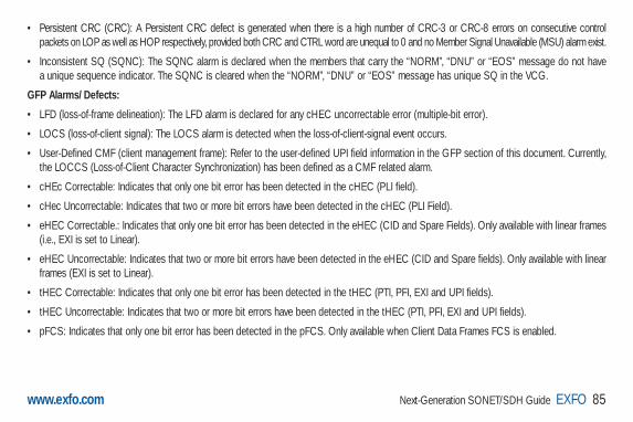
• Persistent CRC (CRC): A Persistent CRC defect is generated when there is a high number of CRC-3 or CRC-8 errors on consecutive control packets on LOP as well as HOP respectively, provided both CRC and CTRL word are unequal to 0 and no Member Signal Unavailable (MSU) alarm exist.
• Inconsistent SQ (SQNC): The SQNC alarm is declared when the members that carry the “NORM”, “DNU” or “EOS” message do not have a unique sequence indicator. The SQNC is cleared when the “NORM”, “DNU” or “EOS” message has unique SQ in the VCG.
GFP Alarms/Defects:
• LFD (loss-of-frame delineation): The LFD alarm is declared for any cHEC uncorrectable error (multiple-bit error).
• LOCS (loss-of-client signal): The LOCS alarm is detected when the loss-of-client-signal event occurs.
• User-Defined CMF (client management frame): Refer to the user-defined UPI field information in the GFP section of this document. Currently, the LOCCS (Loss-of-Client Character Synchronization) has been defined as a CMF related alarm.
• cHEc Correctable: Indicates that only one bit error has been detected in the cHEC (PLI field).
• cHec Uncorrectable: Indicates that two or more bit errors have been detected in the cHEC (PLI Field).
• eHEC Correctable.: Indicates that only one bit error has been detected in the eHEC (CID and Spare Fields). Only available with linear frames (i.e., EXI is set to Linear).
• eHEC Uncorrectable: Indicates that two or more bit errors have been detected in the eHEC (CID and Spare fields). Only available with linear frames (EXI is set to Linear).
• tHEC Correctable: Indicates that only one bit error has been detected in the tHEC (PTI, PFI, EXI and UPI fields).
• tHEC Uncorrectable: Indicates that two or more bit errors have been detected in the tHEC (PTI, PFI, EXI and UPI fields).
• pFCS: Indicates that only one bit error has been detected in the pFCS. Only available when Client Data Frames FCS is enabled.
Next-Generation SONET/SDH Guide EXFO 85www.exfo.com
Guide NEXT-GEN.3-ang: Guide Ethernet.1AN 5/7/07 11:31 AM Page 85

Acronyms Index
Guide NEXT-GEN.3-ang: Guide Ethernet.1AN 5/7/07 11:31 AM Page 86

Next-Generation SONET/SDH Guide EXFO 87www.exfo.com
10. Acronyms IndexADM: Add/Drop Multiplexer
AIS-L: Line Alarm Indication Signal
AIS-P: Path Alarm Indication Signal
APS: Automatic Protection Switching
AU: Administrative Unit
AUG: Administrative Unit Group
BER: Bit Error Rate
BERT: Bit-Error-Rate Test
CDF: Client Data Frame
cHEC: Core Header Error Check
CMF: Client Management Frame
CMF: Client Management Frames
DCC: Data Communications Channel
eHEC: Extension Header Error Check
EXI: Extension Header Identifier
GbE: Gigabit Ethernet
GFP: Generic Framing Procedure
GFP-F: Frame-Mapped
GFP-T: Transparent-Mapped
HO TCM: Higher-Order Tandem Connection Monitoring
HO VCAT: High-Order Virtual Concatenation
LCAS: Link-Capacity Adjustment Scheme
LFD: Loss-of-Frame Delineation
LOCS: Loss–of-Client Signal
LOH: Line Overhead
LOM: Loss of Multiframe
LO VCAT: Low-Order Virtual Concatenation
LTE: Line-Terminating Equipment
MAPOS: Frame-Mapped Multiple Access Protocol over SDH
MFI: Multiframe Indicator
ML-PPP: Multilink PPP
MS: Multiplex Section
MSPP: Multiservice Provisioning Platform
NE: Network Element
OAM&P: Operations, Administration, Maintenance, and Provisioning
OC: Optical Carrier
Guide NEXT-GEN.3-ang: Guide Ethernet.1AN 5/7/07 11:31 AM Page 87
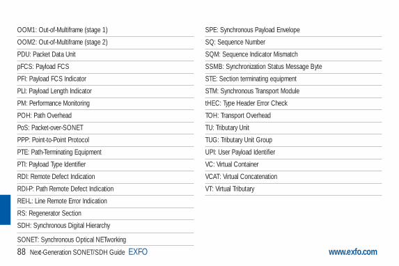
88 Next-Generation SONET/SDH Guide EXFO www.exfo.com
OOM1: Out-of-Multiframe (stage 1)
OOM2: Out-of-Multiframe (stage 2)
PDU: Packet Data Unit
pFCS: Payload FCS
PFI: Payload FCS Indicator
PLI: Payload Length Indicator
PM: Performance Monitoring
POH: Path Overhead
PoS: Packet-over-SONET
PPP: Point-to-Point Protocol
PTE: Path-Terminating Equipment
PTI: Payload Type Identifier
RDI: Remote Defect Indication
RDI-P: Path Remote Defect Indication
REI-L: Line Remote Error Indication
RS: Regenerator Section
SDH: Synchronous Digital Hierarchy
SONET: Synchronous Optical NETworking
SPE: Synchronous Payload Envelope
SQ: Sequence Number
SQM: Sequence Indicator Mismatch
SSMB: Synchronization Status Message Byte
STE: Section terminating equipment
STM: Synchronous Transport Module
tHEC: Type Header Error Check
TOH: Transport Overhead
TU: Tributary Unit
TUG: Tributary Unit Group
UPI: User Payload Identifier
VC: Virtual Container
VCAT: Virtual Concatenation
VT: Virtual Tributary
Guide NEXT-GEN.3-ang: Guide Ethernet.1AN 5/7/07 11:31 AM Page 88

References
Guide NEXT-GEN.3-ang: Guide Ethernet.1AN 5/7/07 11:31 AM Page 89
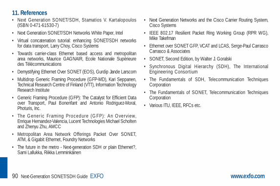
90 Next-Generation SONET/SDH Guide EXFO www.exfo.com
11. References• Next Generation SONET/SDH, Stamatios V. Kartalopoulos
(ISBN 0-471-61530-7) • Next Generation SONET/SDH Networks White Paper, Intel • Virtual concatenation tutorial: enhancing SONET/SDH networks
for data transport, Larry Choy, Cisco Systems • Towards carrier-class Ethernet based access and metropolitan
area networks, Maurice GAGNAIR, Ecole Nationale Supérieure des Télécommunications
• Demystifying Ethernet Over SONET (EOS), Gurdip Jande Larscom • Multidrop Generic Framing Procedure (GFP-MD), Kari Seppanen,
Technical Research Centre of Finland (VTT), Information TechnologyResearch Institute
• Generic Framing Procedure (GFP): The Catalyst for Efficient Dataover Transport, Paul Bonenfant and Antonio Rodriguez-Moral,Photuris, Inc.
• The Gener ic F raming Procedure (G F P) : An Overv iew, Enrique Hernandez-Valencia, Lucent Technologies Michael Scholtenand Zhenyu Zhu, AMCC
• Metropolitan Area Network Offerings Packet Over SONET,ATM, & Gigabit Ethernet, Foundry Networks
• The future in the metro - Next-generation SDH or plain Ethernet?,Sami Lallukka, Riikka Lemminkäinen
• Next Generation Networks and the Cisco Carrier Routing System,Cisco Systems
• IEEE 802.17 Resilient Packet Ring Working Group (RPR WG),Mike Takefman
• Ethernet over SONET GFP, VCAT and LCAS, Serge-Paul CarrascoCarrasco & Associates
• SONET, Second Edition, by Walter J. Goralski • Synchronous Digital Hierarchy (SDH), The International
Engineering Consortium • The Fundamentals of SDH, Telecommunication Techniques
Corporation • The Fundamentals of SONET, Telecommunication Techniques
Corporation • Various ITU, IEEE, RFCs etc.
Guide NEXT-GEN.3-ang: Guide Ethernet.1AN 5/7/07 11:31 AM Page 90

Next-Generation SONET/SDH Guide EXFO 91www.exfo.com
Notes
Guide NEXT-GEN.3-ang: Guide Ethernet.1AN 5/7/07 11:31 AM Page 91

92 Next-Generation SONET/SDH Guide EXFO www.exfo.com
Notes
Guide NEXT-GEN.3-ang: Guide Ethernet.1AN 5/7/07 11:31 AM Page 92