Embed Size (px)
Citation preview
2007-08
Field Training Report
Report submitted to-
Superintending Engineer, Masonary Dam Circle, CDO, Nashik
(23/06/2008-29/06/2008)
AÍkɤÉMü AÍpÉrÉÇiÉÉ, SaÉQûÏ kÉUhÉ qÉÇQûVû, lÉÉÍzÉMü
Superintending Engineer, Masonry Dam Circle, CDO, Nashik
MüÉrÉïMüÉUÏ AÍpÉrÉÇiÉÉ, SaÉQûÏ kÉUhÉ ÌuÉpÉÉaÉ ¢ü.4
Executive Engineer, Masonry Dam Division-IV, CDO, Nashik
xÉUVû xÉåuÉÉ pÉUiÉÏlÉå ÌlÉrÉÑ£üÏ ÌSsÉåsrÉÉ xÉWûÉrrÉMü MüÉrÉïMüÉUÏ AÍpÉrÉÇiÉÉ ´ÉåhÉÏ-1 AÍkÉMüÉîrÉÉÇxÉÉPûÏ ¤Éå§ÉÏrÉ mÉëÍzɤÉhÉ MüÉrÉï¢üqÉ, eÉsÉxÉÇmÉSÉ ÌuÉpÉÉaÉ
Field Training for Direct Recruits - Assistant Executive Engineer (Grade 1) of Water Resource Department.
MüÉsÉÉuÉkÉÏ: 23 iÉå 29 eÉÑlÉ 2008
Duration:23 to 29 June 2008
“¤Éå§ÉÏrÉ mÉëÍzɤÉhÉ AWûuÉÉsÉ” “FIELD TRAINING REPORT”
xÉÉSUMüiÉÉï-
mÉëÌuÉhÉ MüÉåsWåû, oÉÏ.D.(ÍxÉÎuWûsÉ), LqÉ.OåûMü. (AÉrÉ. AÉrÉ. OûÏ.- MüÉlÉmÉÔU)
(xÉWûÉrrÉMü MüÉrÉïMüÉUÏ AÍpÉrÉÇiÉÉ)
Submitted by-
Pravin Kolhe, BE (Civil), MTech (IIT-Kanpur) (Assistant Executive Engineer)
Field Training Report: Masonry Dam Division‐4, CDO, Nashik (23~29.06.2008)
Report Submitted by: Er. Pravin Kolhe, AEE (WRD) Page ii
Executive Summary
aharashtra Engineering Training Academy (META), Nashik organized training program for direct recruits - Assistant Executive Engineer & Assistant Engineer (Class I) of Water
Resource Department (WRD), in accordance with Maharashtra Engineering Service Examination-2004. As per schedule of training program, we were directed to undergo training under the guidance of Superintending Engineer- Shri. Rajendra Jaltare saheb, Masonry Dam Circle, Central Design Organization, Nashik.
The training program was scheduled for one week and started on 23rd June 2008 and we were directed to study about Design of Masonry dam and its components under the guidance of Executive Engineer- Shri. V.V. Sulakhe saheb. We interacted with him and he guided us on subjects related to masonry dam such as General layout of dam, design of overflow and non-overflow section, design of energy dissipation arrangement and RCC pier, Guide wall and spray wall, design of drainage galley, design of barrage, grouting, and future challenges such as Foundation of dam on soft soil, and strengthening of masonry dam.
This report includes the day-to-day details of training program at Masonry Dam Division No-4, Masonry Dam Circle, Central Design Organization, Nashik. While writing this report, I had gone through various design standards like Design Process Manual, IS Codes, Central Design Organization, Nashik Standards, CWC Standards etc and I had given these references in the appropriate locations. The report also contains the study and observations performed by me. I learned valuable knowledge regarding Design Procedure of masonry dam through guidance by officers as well as reference material.
M
Field Training Report: Masonry Dam Division‐4, CDO, Nashik (23~29.06.2008)
Report Submitted by: Er. Pravin Kolhe, AEE (WRD) Page iii
Acknowledgement
take this opportunity to express my gratitude to those whose active help and support make this report possible in the present form.
First of all, I express my sincere gratitude to Shri. Rajendra Jaltare, Superintending Engineer, Masonry Dam Circle, Central Design Organization, Nashik for insisting in me the drive to work hard and for inculcating in me the discipline to think clearly.
It is the endless guidance and constant encouragement of Er. V.V. Sulakhe Saheb, Executive Engineer (Masonry Dam Division-IV) and I would like to express my heartfelt gratitude to him and his staff for providing me necessary technical information. He shared his valuable experiences with us and it was the most enjoyable part of training.
My special thanks to deputy engineer’s- Shri. L.G. Joshi, and Shri. S.S. Challawar for their active help and valuable guidance. All the reports and reference materials were available for my study purpose.
Definitely the knowledge, I received during this training session was a lifetime experience and it will serve as a foundation for my career in Water Resources Department.
Last, but not least, I wish to express my gratitude towards my parents- Shivaji and Rohini, my grandparents- Rangnath and Sitabai, my uncle Raosaheb and aunty Radhika who sacrificed a lot to give me a good education.
- Pravin Kolhe BE (Civil), MTech (IITK) (Assistant Executive Engineer)
I
Table of Content
Chapter 1. About Central Design Organization, Nashik ................................................................... 3
1.1 Establishment of Central Design Organization, Nashik ........................................................ 3
1.2 Activities of CDO ................................................................................................................................... 3
1.3 Organizational Structure ................................................................................................................... 4
Chapter 2 Masonry Dam Circle ................................................................................................................... 5
2.1 Organizational Setup of Masonry Dam Circle ........................................................................... 5
2.2 Role of Earth Dam Circle .................................................................................................................... 5
2.3 Major achievement of Masonry Dam Circle ............................................................................... 6
2.3 Masonry Dam Circle is Consultant to- .......................................................................................... 7
2.4 Field Data For Gravity Dams ............................................................................................................ 7
2.5 Major Projects Designed by Masonry Dam Circle .................................................................... 8
2.5 Lift irrigation Schemes Designed by Masonry Dam Circle ................................................... 8
Chapter 3 General Layout of Masonry Dam .......................................................................................... 9
3.1 General Layout of dam ....................................................................................................................... 9
3.1.1 Procedure to be followed- ......................................................................................................... 9
3.1.2 Layout of Gravity (Masonry) dam .......................................................................................... 9
3.2 Design of Overflow Section ............................................................................................................ 10
3.2.1 Design of Ogee Type Spillway ............................................................................................... 10
3.3 Design of Non-Overflow Section .................................................................................................. 11
3.4 Energy Dissipation Arrangement ................................................................................................. 11
3.4.1 Type of EDA ................................................................................................................................... 12
3.4.2 Factors Affecting Selection of Type of EDA ...................................................................... 12
3.5 Drainage Gallery and Sump Well ................................................................................................. 12
3.5.1 Layout of Drainage Gallery ..................................................................................................... 13
3.6 Sump Well ............................................................................................................................................. 13
3.7 Adits ......................................................................................................................................................... 13
3.8 Spillway Pier ......................................................................................................................................... 13
3.9 Divide Walls/ Guide Walls/ Spray walls ................................................................................... 14
3.9.1 Divide Walls .................................................................................................................................. 14
Field Training Report: Masonry Dam Division-4, CDO, Nashik (23~29.06.2008)
Report Submitted By: Er. Pravin Kolhe, AEE, (WRD) Page 2
3.9.2 Guide Walls .................................................................................................................................... 14
3.9.3 Spray walls .................................................................................................................................... 14
3.10 Instrumentation ............................................................................................................................... 14
3.11 Foundation Grouting ....................................................................................................................... 15
Chapter 4. Design of Barrage Layout and Strengthening of Dam .............................................. 16
4.1 Introduction ......................................................................................................................................... 16
4.2 Field Data ............................................................................................................................................... 16
4.3 Design Procedure ............................................................................................................................... 16
4.4 Loading Considerations ................................................................................................................... 17
4.5 Necessity of Strengthening of Dam ............................................................................................ 17
4.5.1 Design Concepts .......................................................................................................................... 17
4.5.2 Signs of Distress ......................................................................................................................... 17
4.5.3 Raising of Dams ........................................................................................................................... 18
4.6 Investigation ........................................................................................................................................ 18
4.7 Methods of Strengthening .............................................................................................................. 18
Chapter 6. Conclusion .................................................................................................................................. 19
Field Training Report: Masonry Dam Division-4, CDO, Nashik (23~29.06.2008)
Report Submitted By: Er. Pravin Kolhe, AEE, (WRD) Page 3
Chapter 1. About Central Design Organization, Nashik
1.1 Establishment of Central Design Organization, Nashik
Development programme to harness the available irrigation potential and also to increase the power resources were undertaken by the state of Maharashtra, India on a larger scale after independence by construction of dams and hydro power projects. To cope up with the need of providing designs of earth and gravity dams. Central Designs Organization (C.D.O) was established in 1957 by the Government of Maharashtra.
The CDO at that time had to start from scratch, but because of continuing efforts of the Engineers working in the CDO, the Organization is now recognized nationwide as a pioneer Design Organization in the field of Dam Design. Organization was strengthened for undertaking design of Hydro Electric Projects. It has now established its own design practices from the experience gained from the designs prepared and executed for last 51 years which has stood the test of the time and which are commensurate with the relevant BIS Code and USBR provisions.
CDO is located at Nashik a central place connected with rail and road. It has its own building and residential quarters for the staff. The pioneer research institute of the state, Maharashtra Engineering Research Institute (MERI) is located in the same premises, which is complementary for the Design. 1.2 Activities of CDO
Design of irrigation project /Design of Hydro Electric Project / Design of Lift Irrigation Scheme.
Hydrology, Yield, Flood, Simulation studies and Flood routing. Detailed design of Earth dam, Gravity dam and its junctions. Design of different types of spillways / Energy dissipation arrangements. Instrumentation. Design of various types of Outlets. Design of all types of Gates. Design of various types of Major Canal Structures. Design of Hydro Electric Projects. Design of lift Irrigation Schemes. Review of old dams and suggesting remedial measures, if required. Scrutiny of Project Report for C.W.C. Clearance. Working on different Committees of BIS for preparation of various
standards. Consultancy services for Semi Government / Private Sectors.
Field Training Report: Masonry Dam Division-4, CDO, Nashik (23~29.06.2008)
Report Submitted By: Er. Pravin Kolhe, AEE, (WRD) Page 4
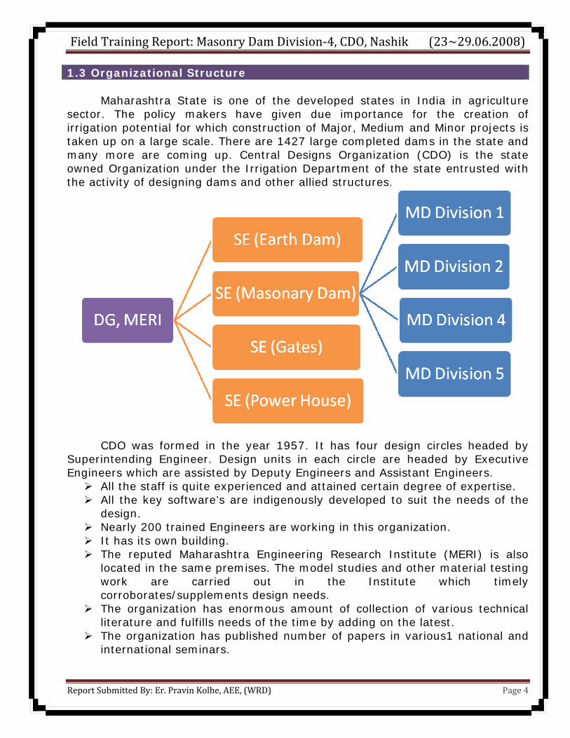
1.3 Organizational Structure
Maharashtra State is one of the developed states in India in agriculture sector. The policy makers have given due importance for the creation of irrigation potential for which construction of Major, Medium and Minor projects is taken up on a large scale. There are 1427 large completed dams in the state and many more are coming up. Central Designs Organization (CDO) is the state owned Organization under the Irrigation Department of the state entrusted with the activity of designing dams and other allied structures.
CDO was formed in the year 1957. It has four design circles headed by Superintending Engineer. Design units in each circle are headed by Executive Engineers which are assisted by Deputy Engineers and Assistant Engineers.
All the staff is quite experienced and attained certain degree of expertise. All the key software’s are indigenously developed to suit the needs of the
design. Nearly 200 trained Engineers are working in this organization. It has its own building. The reputed Maharashtra Engineering Research Institute (MERI) is also
located in the same premises. The model studies and other material testing work are carried out in the Institute which timely corroborates/supplements design needs.
The organization has enormous amount of collection of various technical literature and fulfills needs of the time by adding on the latest.
The organization has published number of papers in various1 national and international seminars.
Field Training Report: Masonry Dam Division-4, CDO, Nashik (23~29.06.2008)
Report Submitted By: Er. Pravin Kolhe, AEE, (WRD) Page 5
Chapter 2 Masonry Dam Circle
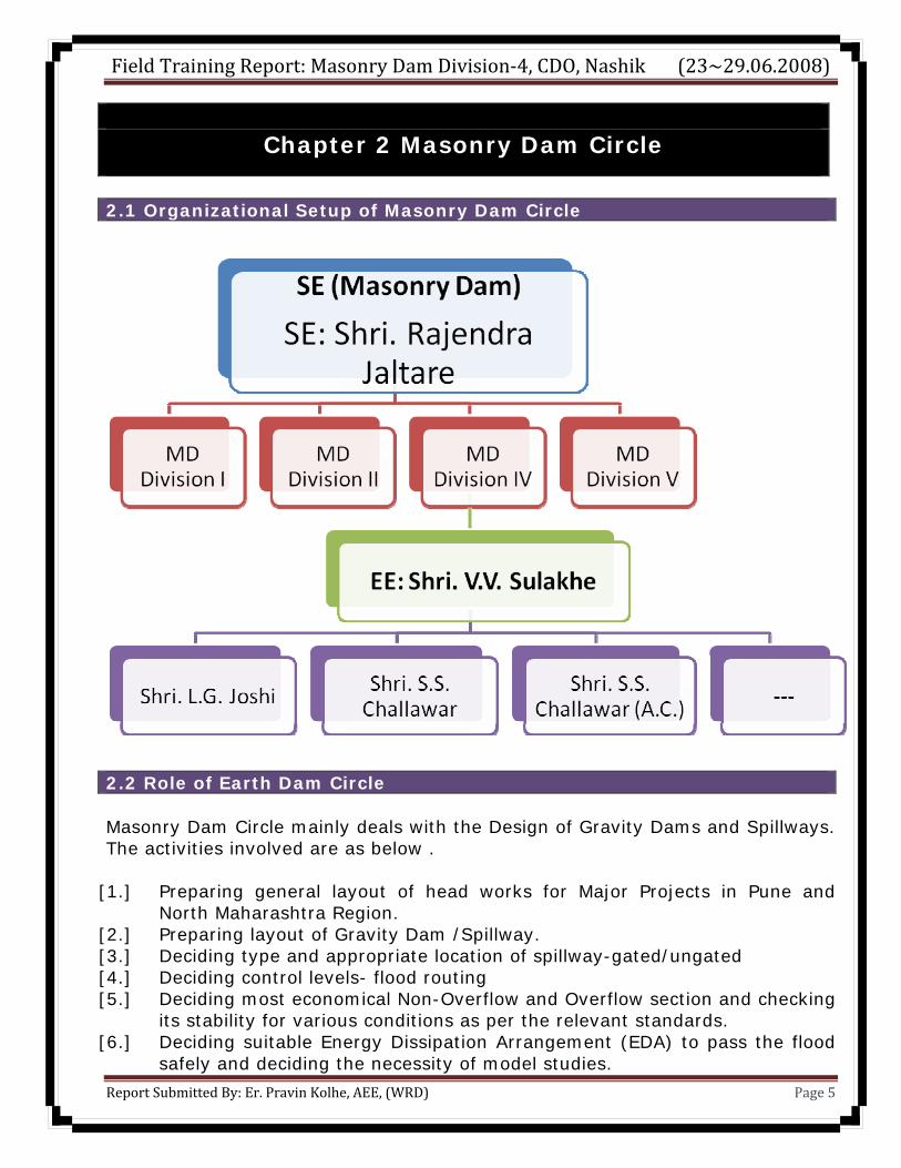
2.1 Organizational Setup of Masonry Dam Circle
2.2 Role of Earth Dam Circle Masonry Dam Circle mainly deals with the Design of Gravity Dams and Spillways. The activities involved are as below .
[1.] Preparing general layout of head works for Major Projects in Pune and North Maharashtra Region.
[2.] Preparing layout of Gravity Dam /Spillway. [3.] Deciding type and appropriate location of spillway-gated/ungated [4.] Deciding control levels- flood routing [5.] Deciding most economical Non-Overflow and Overflow section and checking
its stability for various conditions as per the relevant standards. [6.] Deciding suitable Energy Dissipation Arrangement (EDA) to pass the flood
safely and deciding the necessity of model studies.
Field Training Report: Masonry Dam Division-4, CDO, Nashik (23~29.06.2008)
Report Submitted By: Er. Pravin Kolhe, AEE, (WRD) Page 6
[7.] Detailed design of all components of Gravity Dam and EDA a. Gallery and adits b. Lift well and stair case c. Crest d. Glacie e. Drainage arrangement f. Piers and Bridge g. Spray wall h. Guide wall i. Tail channel and protective arrangement
[8.] Design of junction between Earthen Dam and Gravity Dam. [9.] Provision of various types of instruments.
[10.] Review of Old Gravity Dam and suggesting strengthening measures like buttressing and full backing/ cable strengthening.
[11.] Suggesting remedial measures for the various problems faced by the Gravity Dams seepage etc.
[12.] Checking of the project report to be submitted to Central Water Commission for clearance of Amravati region and North Maharashtra region.
[13.] Deciding the suitability of foundation of dam , mapping of foundation and preparing geological reports from the Subsurface investigations ,through geological unit headed by the Senior Geologist.
[14.] Providing consultancy services to Semi Government and Private Organisations.
[15.] Working of various committees of Beauro of Indian Standards (BIS) for updating the standards.
All the data required for the design needs to be supplied by the field, offices. 2.3 Major achievement of Masonry Dam Circle • Successfully carried out design of 85 m. high Masonry Dam. • Introduced colgrout masonry construction for Gravity Dam. • Provided designs for strengthening of 12 old Gravity Dams. • Morning Glory Type spillway for Kasarde project near Kolhapur. • Side Channel spillway for Chapdoh project near Yeotmal. • Design of Lift irrigation Schemes . • Standardisation of K.T. Weir of different road (slab) width. • Design of K.T. Weir in permeable strata with concrete diaphragm. • Design of K.T. Weir with raft on impermeable soil strata. • Design of Labyrinth type weir. • Design of Barrages on Tapi river.

Field Training Report: Masonry Dam Division-4, CDO, Nashik (23~29.06.2008)
Report Submitted By: Er. Pravin Kolhe, AEE, (WRD) Page 7
2.3 Masonry Dam Circle is Consultant to- Maharashtra Industrial Development Corporation, Maharashtra State Electricity Board, Maharashtra Jeewan Pradhikaran. Mumbai Municipal Corporation, Nashik Municipal Corporation, M/s Tata Power Company, Sahara India Housing Corporation Ltd., Mumbai. M/s Nippon Denro Co. Ltd., Bombay Sub-urban Electricity Board. 2.4 Field Data For Gravity Dams
1) Administratively approved Project Report 2) Copy of approved / proposed general layout 3) Gross storage 4) Live storage 5) Dead storage 6) Dependability 7) Control levels 8) Flood. 9) Other salient features.
Details of spillway. Pier resting on foundation or overflow. Gated/un-gated End Pier resting on OF/ NOF/ Divide wall. If gated, no. & size of gates. Design inflow flood Length of spillway. Corresponding outflow No. of piers Type of junction. Width of pier. Type of EDA.
10) Block contour plan showing the proposed dam alignment and project layout covering an area 300 m. upstream and downstream of approved alignment.
11) Dam site studies. 12) Geological Report including bore hole data with logging including
water-in-take at various depths. a. Bores on L-section of dam. b. Bore holes for spillway, approach and tail channel. c. Bore holes at outlet location.
13) Soil properties for proposed earth dam. Borrow area plan showing quantities of embankment material available.
14) Hydraulic Data- a. L-Section and contour plan of tail channel (with rock contours)
showing bed slopes. b. Tail water curve for various discharges.
Field Training Report: Masonry Dam Division-4, CDO, Nashik (23~29.06.2008)
Report Submitted By: Er. Pravin Kolhe, AEE, (WRD) Page 8
c. Area capacity curve drawn by area reduction method. Area and the capacity on the basin for about 2m above the probable M.W.L.
d. Upstream constraints for fixation of M.W.L. and downstream constraints for flood releases.
e. River carrying capacity. 15) Information about provision of construction and river sluices.
2.5 Major Projects Designed by Masonry Dam Circle 1. Arunawati 2. Bagh 3. Bhawanthadi 4. Bembla5. Bhama Askhed 6. Bhandardara 7. Bhatsa 8. Bhima 9. Bhima Sina (Joint Canal)
10.Chaskaman 11. Dhombalkwadi 12. Dudhganga
13.Ghod 14. Girna 15. Godavari (Dharna) 16. Gosikhurd17. Gunjawani 18. Human 19. Itiadoh 20. Jayakwadi 21. Jayakwadi (ll) 22. Jigaon 23. Kadava (Karanjawan) 24. Kadwa 25. Kai 26. Kalisarar 27. Khadakpurna 28. Khadakwasla 29. Khodshi gated weir
30. Krishna 31. Krishna Canal (Extension)
32. Kukdi
33. Lendi 34. Lower penganga 35. Lower Dudhana 36. Lower Tapi 37. Lower Terna 38. Lower Wardha 39. Lower Wunna 40. Manjra 41. Mula 42. Nandur
Madhameshwar 43. Neera Deoghar 44. Neera L.B.C.
45. Pench 46. Punad 47.Purna (Siddeshwar/yeldari)
48. Pus
49. Sangola Branch Canal
50. Sina Kolegaon 51. Surya 52. Talamba
53. Tarali 54.Temghar 55. Tillari 56.Tulshi57. Tultuli 58. Upper Penganga 59. Upper Wardha 60. Upper
Godawari 61. Upper Prawara 62. Upper Tapi st-I 63. Urmodi 64. Veer
65. Vishnupuri 66. Waghur 67. Wan 68. Warangaon Talvel
69. Warna 2.5 Lift irrigation Schemes Designed by Masonry Dam Circle 1. Barshi 2.Bhagpur 3. Bodwad 4. Dahigaon 5. Ekrukh 6. Janai Shirasai 7.Jilhekathapur 8.Krishna Koyana 9.Kurha Wadoda 10.Purandhar 11.Shirapur 12.Sina Madha 13. Tembhu
Field Training Report: Masonry Dam Division-4, CDO, Nashik (23~29.06.2008)
Report Submitted By: Er. Pravin Kolhe, AEE, (WRD) Page 9
Chapter 3 General Layout of Masonry Dam
3.1 General Layout of dam
The deputy engineer in charge of work will be responsible for preparing the layout based on the field data and to prepare data sheet approved from Executive Engineer. Executive Engineer will verify the field data with its source. Assumptions to be made in absence of data shall be approved from Superintending Engineer, who will submit the same to competent authority for approval. 3.1.1 Procedure to be followed-
1. Preparation of data sheet and approval of Executive Engineer. 2. Location of spillway based on bore data, suitability of EDA1, tail channel
layout, economical studies and approach to the spillway. 3. Type of dam based on economy and resources. 4. Siltation Studies as per CBIP2 Technical Report No. 19. 5. Flood Studies as per IS: 11223-1985. 6. Type of spillway: Gated/Un-gated. 7. Free Board as per IS:6512-1984 and IS:10635-1993. 8. Control Levels such as MDDL, Sill Level/Power Outlet Level, FRL, MWL, TBL.
3.1.2 Layout of Gravity (Masonry) dam Following are important components while deciding the layout of masonry dam-
1. Non-Overflow Section/Overflow Section (IS:10135-1985) 2. Monolith Arrangement (IS:11155-1994) 3. Pier (IS:13551-1992) 4. Type of EDA (IS:10137-1982)
a. Horizontal Stilling Basin b. Roller Bucket (Slotted/Solid) c. Flip Bucket
5. Guide Wall and Spray Wall (IS:12720-1989) 6. Grouting
a. Consolidation Grouting b. Curtain Grouting
7. Gallery (IS:10135-1985) 8. Junction
1 Energy Dissipation Arrangement 2 Central Board for Irrigation and Power
Field Training Report: Masonry Dam Division-4, CDO, Nashik (23~29.06.2008)
Report Submitted By: Er. Pravin Kolhe, AEE, (WRD) Page 10
9. Contraction Joints (IS:12200-1987) 10. Instrumentation (IS:7436-1976) 11. Bridge 12. Construction Sluice 13. Earth Dam (Designed by Earth Dam Circle of CDO, Nashik) 14. Head Regulator
3.2 Design of Overflow Section Essential Field data for design of OF1 section-
1. Finalization of design flood 2. Geological report and foundation level 3. Finalization of construction material 4. Finalization of Control levels 5. Fetch Calculations and Free Board 6. Other data like, river bed slope, contour map, flood ordinates etc.
OF sections are provided in the spillway portion of masonry/concrete dam. There are following two types of OF sections commonly adopted in Maharashtra-
I. Ogee Type (IS: 6934-1973) II. Narrow/Broad Crest Weir.
3.2.1 Design of Ogee Type Spillway 1. Hydraulic Design IS:6934-1973 2 Profile of Ogee Type OF Section USBR-Design of
Small Dams, Chapter IX
3 Structural Design 3.1 Dead Load
IS:6512-1984- “Criteria for Design
of Solid Gravity Dams”
3.2 Reservior and tail water load 3.3 Uplift Pressure 3.4 Earthquake Forces 3.5 Earth and Silt Pressure 3.6 Ice Pressure 3.7 Wind Pressure 3.8 Wave Pressure 3.9 Thermal Loads 4 Load Combinations for Design Purpose IS:6512-1984 5 Stability Analysis 6 Check for Sliding and Overturning IS:6512-1984 7 Foundation IS:11155-1995 8 Foundation Treatment CDO/MD/GRT-1988 9 Crest for Ogee Section IS:11155-1995 1Over Flow
Field Training Report: Masonry Dam Division-4, CDO, Nashik (23~29.06.2008)
Report Submitted By: Er. Pravin Kolhe, AEE, (WRD) Page 11
10 Construction Material Circular:09.07.200211 Glacis Concrete IS:11155-1995 12 Provision of Drainage Gallery IS:10135-1985 13 Fillet Provision Concrete Dam by
R.S. Varshney 14 Foundation Anchors for Protection against
vibration
15 Width of Full on upstream 16 Approach Conditions 17 Cold Joint 18 Contraction Joints and Monoliths IS:12200-2000 and
IS:11155-1995 19 Instrumentation
3.3 Design of Non-Overflow Section Selection of NOF depends upon the site condition. Normally an irrigation or hydropower project envisages construction of composite dam. Major part of dam consist of earthen embankment and masonry/concrete masonry /concrete part mainly consist of two components as under-
1. OF section to pass the design flood 2. NOF/Divide Wall and Wing Wall to retain the adjoining earthen
embankment. As per Government of Maharashtra Marathi circular dt. 09.07.2002, construction of UCR masonry for dam is totally banned. Hence NOF portion as per further directives in circular, colgrout masonry can be constructed if best quality natural sand is available and quantum of work is comparatively small. This implies that either complete dam is to be constructed with u/s septum in M15 CC1 with backing portion in colgrout masonry or concrete of grade not less than M10 CC. 3.4 Energy Dissipation Arrangement Following field data is required-
1. Tail Water Rating Curve 2. Bore Hole Data 3. Geological Report 4. Block Contour Plan at the location of EDA 5. Downstream river carrying capacity of parent channel, if spillway is located
in gorge. 6. Block contour plan showing alignment of Tail Channel upto confluence. 7. L-Section of tail channel up to confluence showing GL.
1 Cement Concrete
Field Training Report: Masonry Dam Division-4, CDO, Nashik (23~29.06.2008)
Report Submitted By: Er. Pravin Kolhe, AEE, (WRD) Page 12
3.4.1 Type of EDA
3.4.2 Factors Affecting Selection of Type of EDA
1. Frequency and Intensity of Design Flood. 2. The degree of protection (to be provided for very high floods) 3. Type of dam and its spillway 4. Proximity of Power house tailrace and other structures 5. Nature of foundation 6. Velocity and nature of flow. 7. Elevation of tail water at various discharges. 8. Safety of existing structures on downstream. 9. Any special consideration such as deep pool of water in close proximity of
dam on its downstream. 3.5 Drainage Gallery and Sump Well The necessity of foundation and inspection gallery will be decided based on the following criteria-
1. Foundation gallery shall be provided in the body of dam where height of water column (FRL) above normal foundation level is more than 20m. (measured up to crest level in the case of un-gated spillway)
2. For water head more than 40m up to 60 m inspection gallery shall be provided.
Field Training Report: Masonry Dam Division-4, CDO, Nashik (23~29.06.2008)
Report Submitted By: Er. Pravin Kolhe, AEE, (WRD) Page 13
3. For every 20 m increase in the head beyond 60 m additional inspection gallery shall be provided.
3.5.1 Layout of Drainage Gallery Following provisions shall be made as per IS: 12966-Part II-1990 and present CDO code of practice-
1. Size : 1.5 x 2.3 m Thickness : 0.75 m 2. Floor level: 1.5 to 2 m above the Foundation RL 3. Trade of step = 250 mm and rise = 200 mm, if slope of the
foundation is steeper than 17. Landing shall be provided for every 5 m rise in the formation level. Provision of MS angles of 25 mm shall be made as noses to the steps to avoid damage during hauling of machinery.
4. Gutter : 300 x 300 mm on upstream side of floor of gallery.
5. Location: Minimum distance from upstream face of dam to upstream inner face of gallery shall be 5% of water head or 3 m (minimum)
6. Provision of lift, if height exceeds 40 m. 7. PVC water stop as per IS:12200-2000
3.6 Sump Well
Capacity of sump well shall be worked out on the basis of seepage collected in the gallery in 30 minutes at the rate of 0.3 Cum/100 m length /meter average head and efforts shall be made to drain out gallery by gravity. Gallery shall be designed as per IS:10135-1985 and as per IS:12966 (Part II)-1990. 3.7 Adits
1. Adits shall be provided for access to the gallery from downstream side. 2. Size: 1.5 x 2.3 m 3. Design criteria is similar to that of Galleries 4. Easy access to the inspection gallery and foundation gallery shall be
ensured 5. For dams having more than one gallery, provision of staircase cum lift well
shall be in invariably made at suitable locations. 6. In case of ‘V’ shaped gorges, where layout of adit requires cutting provision
of staircase/shaft shall be made. 3.8 Spillway Pier
Field Training Report: Masonry Dam Division-4, CDO, Nashik (23~29.06.2008)
Report Submitted By: Er. Pravin Kolhe, AEE, (WRD) Page 14
The design of spillway pier shal be undertaken after receiving radial gate general layout prepared by Gates Circle of Central Design Organization, Nashik. Spillway pier shall be desiged in accordance with IS:6512-1984, IS:13551-1992, IS:SP 55-1993, IS 456-2000. M20 CC grade is recommended to Government and shall be adopted after Government approval. 3.9 Divide Walls/ Guide Walls/ Spray walls 3.9.1 Divide Walls Divide walls are provided for separating spillway from earth dam. This wall is parallel to earth dam profile so that earth work will not enter in to flow of Spillway and approach channel. The wall shall rest on sound foundation rock. This is important part of dam so important factor is to be taken as per that of Overflow and Non-overflow. 3.9.2 Guide Walls Guide walls are provided on sides of EDA. Similarly guide walls are provided to guide the flows in approach and tail channels and protect the banks if necessary. The walls shall rest on sound foundation rock. Importance factor should be taken as One. 3.9.3 Spray walls Spray walls are provided to obstruct the outflanking of outflow of spillway. Spray walls are resting on overflow or adjacent non-overflow and guide walls and at the top they are obutted to end piers. 3.10 Instrumentation From considerations of usefulness of data obtainable, importance of data and cost aspects the measurement required can be grouped in two categories.
1) Obligatory measurements :- 2) Optional Measurements
1) Obligatory Measurements
Following Types of measurements are required to be done as Obligatory in case of masonry/concrete dams.
a. Uplift pressure measurement, arrangement to give information regarding uplift.
b. Seepage measurements on D/s. and in galleries. c. Temperature of the interior of the dam as determined by thermometers d. Displacement measurement.
Field Training Report: Masonry Dam Division-4, CDO, Nashik (23~29.06.2008)
Report Submitted By: Er. Pravin Kolhe, AEE, (WRD) Page 15
2) Optional measurements :-
Certain optional measurements would be warranted for high dams and for dams with a special considerations in respect of unusual design, difficult & doubtful foundations for monitoring and verification of design criteria.
a. Rock and foundation deformation. b. Tilt. c. Stress d. Strain e. Pore pressure f. Seismicity
Instruments are classified in to mechanical, hydraulic, Pneumatic, Electrical/ Electronic (resistance type & vibrating wire type) Optical and Fibre Optic sensors type based on working principle. Separate or combination of these are also used when required.
3.11 Foundation Grouting Very often seams and faults or band of shattered rock extending to large depths may be encountered during drilling or excavation of foundation. Such weak material will not take appreciated load and the structure will have transfer the load to the firm rock on the two sides of the weak zone by spanning over it, thus leading to stress concentrations both in the foundation rock and the structure. Sine it is not practicable to remove the weak material to its fall depth. The technique used to consolidate the foundation rock is pressure grouting. Pressure grouting technique is the process of injecting suitable cementituous slurries or similar material into inaccessible places for the purpose of seams, cracks and fissures or filling voids. While the principal used of this process is to fill openings in a structural mass and render it impervious to percolating water. It is also used to improve the strength and elastic properties of the material into which it is injected. The principal purpose of foundation grouting is to establish an effective barrier against flow of water. Thereby preventing leakage and reducing the hydrostatic uplift pressure under the structure. Another purpose is to fill the voids in the near surface rock under the structure and thus secure more uniform and monolithic foundation.
Field Training Report: Masonry Dam Division-4, CDO, Nashik (23~29.06.2008)
Report Submitted By: Er. Pravin Kolhe, AEE, (WRD) Page 16
Chapter 4. Design of Barrage Layout and
Strengthening of Dam
4.1 Introduction It is a barrier provided with a series of gates over its entire length across the river to store water & regulate the water level and pattern of flow upstream. Location for a barrage shall be decided on the consideration of its suitability for the purpose it has to serve. e.g. for irrigation purpose. The head works shall be planned in such away that full command may be obtained by a barrage of reasonable height. At the location of barrage, the river reach should be straight as far as possible so that velocities shall be uniform and the sectional area of upstream of barrage is fairley constant. The banks should be preferably high, well defined and inerrodable. The alignment of a barrage should be such as to ensure normal and uniform flow through all barrage bays as far as possible. Therefore perpendicular alignment is preferable to skew alignment. 4.2 Field Data For study of field data, the following points shall be observed which are essentially required for the design of barrage.
1. Contour plan at the location of Barrage, showing details viz. Command, roads etc.
2. Geological Report based on bore data (with water intake test results & core recovery) on barrage alignment and upstream & downstream of barrage as specified for that particular barrage site.
3. Detail survey showing c/s of the river upstream & downstream of the barrage & ‘L’ section of river for a distance as specified for that particular barrage site.
4. Submergence Plan at F.R.L. & M.W.L. 5. Design flood (Inflow Hydrograph). 6. Availability of construction material. 7. General Layout of Barrage approved by competent field authority with due
cognizance of above referred points. 4.3 Design Procedure Barrage structure proper essentially has following components.
Field Training Report: Masonry Dam Division-4, CDO, Nashik (23~29.06.2008)
Report Submitted By: Er. Pravin Kolhe, AEE, (WRD) Page 17
1. Spillway portion with vetical lift gates with sill necessarily at average river bed level.
2. Divide wall or N.O.F. on either side of spillway as per site situation. 3. Pier & Bridge . 4. E.D.A. arrangement to pass spilled over water by dissipating energy to the
downstream river portion. Components of barrage :-
1. Spillway. 2. Divide wall 3. Key Wall 4. Non overflow section 5. Pier 6. Bridge 7.
4.4 Loading Considerations Various wheel loads and dimensions as per IRC code of practice for Road Bridges - section II are to be considered as under- i) Class AA ii) Class B iii) Service Gate crane loading iv) Goliath crane loading. 4.5 Necessity of Strengthening of Dam The different conditions in which the strengthening of dams is required are as below. 4.5.1 Design Concepts
Many of the old dams ware designed without considering uplift force and / or earthquake force. In some cases the earthquake forces considered are inadequate. These dams with present design norms, are found to be unsafe. Such dams though they may not have shown signs of any distress, will have to be strengthened so as to increase their serviceable life, and to avoid any sudden danger of failure, causing loss of life and property. While raising of the dam to increase storage capacity, the existing dam needs to be strengthened. 4.5.2 Signs of Distress
Due to inadequate design assumptions or failure to achieve the stipulated strength or loss of strength due to aging or due to some unknown geological and / or other factors like increased seismic activities a dam may show sudden or progressive signs of distress indicated by increase in leakages, excessive
Field Training Report: Masonry Dam Division-4, CDO, Nashik (23~29.06.2008)
Report Submitted By: Er. Pravin Kolhe, AEE, (WRD) Page 18
deflections, spouts of jets from downstream face and visible cracks etc. In such cases, emergency measures and then permanent strengthening measures are required to be taken.
4.5.3 Raising of Dams
Some dams become unserviceable due to silting or in some cases the capacity has to be increased. To restore the original capacity of reservoir or to increase the capacity, some times it is economical and feasible to raise the old dam. While raising, the dam may need strengthening. 4.6 Investigation When it is decided that the dam need strengthening, the following investigations are required to be carried out to decide the method of strengthening.
1. Density of old dam is required to be ascertained as it is very important parameter in the design of gravity dam. Care should be taken that the density taken should be worst as this portion of dam would be vulnerable.
2. The compressive and tensile strength of the dam shall be decided by testing the sample cores. In case it is not possible to take out cores, then Non-destructive test by measuring wave-velocity may be carried out. Based on these strength values, the methods and criteria for strengthening can be fixed.
3. In case of distress such as cracking or excessive leakages, the detailed investigations such as the extent of cracking, the source of leakage etc. needs to be made very carefully to decide upon further treatment. Depending upon the signs of distress and the stress picture in pseudostatic analysis if it is found necessary, dynamic analysis is to be carried out.
4. The instrumentation data if available also shall be studied. 5. Any other relevant investigations depending upon the situation shall be
carried out, particulars for deciding earthquake parameters, if the area is seismically active, etc.
4.7 Methods of Strengthening
I. Post-tensioning cables. II. Earth backing.
III. Providing drainage gallery. IV. Masonry or concrete backing.
Field Training Report: Masonry Dam Division-4, CDO, Nashik (23~29.06.2008)
Report Submitted By: Er. Pravin Kolhe, AEE, (WRD) Page 19
Chapter 6. Conclusion
The training session at Masonry Dam Division-4 of Masonry Dam
Circle, Central Design Organization, Nashik, was the most enjoyable
session for me. I joined Masonry Dam Division-4 on 23rd June 2008
under the guidance of Executive Engineer - Shri. V.V. Sulakhe
saheb and interacted with him along with the staff of division.
Training session ended on 29th June 2008 and this report includes the
summary of the training.
I learned the procedure of Design of Masonry Dam, Design of
barrage and its components and strengthening of dam.
It was nice experience for me since I could realize the
importance of Masonry Dam Design Division.
At last, I am thankful to Superintending Engineer- Shri.
Rajendra Jaltare, Saheb, Executive Engineer- Shri. V.V. Sulakhe
saheb, and Sub-Divisional Engineer Shri. L.G. Joshi & Shri. S.S.
Challawar and all the staff of division for providing me an
opportunity to enjoy the thrill of design and providing all the
necessary documents and related procedure.
Pravin Kolhe BE (Civil), MTech (IIT-K). Assistant Executive Engineer, Water Resource Department,
Government of Maharashtra.