Embed Size (px)
Citation preview

Issued November 2009 12497
DATA SHEET
TR SERIES OVERLOAD
RELAYS Based on D&C Catalog 19th Edition Revised No. 01

TR-5-1N/3 TR-N3/3
TR-N12H/3
AF-1383
AF00-141
AF88-1379
AF00-139
AF00-143
AF00-282
TR–0N �H/3A
Frame size0N to N14
OperationBlank: Standard operationL: Long time operationQ: Quick operation
ResetBlank: Manual resetA: Auto reset
No. of heater elementsBlank: 2-element (TR)
3-element (TK, TR-Q)3: 3-element (TR)
MountingBlank: On-contactor
mountingH: Separate mounting
TR-N6/3
TR-0N/3
TR-N8/3
■ Type number nomenclature
Thermal Overload RelaysTR seriesGeneral information
Standard type thermal overloadrelays
■ Description• Highly reliable thermal overloadrelaysFUJI thermal overload relays aredesigned to provide overload protectionto meet the thermal characteristics oflow voltage induction motors.Adjustable thermal overload relays givemotors positive overcurrent protection.The starter contacts cannot be heldclosing under overload conditions.However, once the bimetal element hascooled, the reset button can bedepressed and the motor can berestarted in the normal manner.Ordinarily this reset is carried outmanually but the starter can bechanged over to ‘automatic reset’ bymeans of a screw-driver.• FUJI thermal overload relay issubjected to stringent testing in thefactory to check performance andactual values are calibrated with themarkings on the adjustable dial.Consequently, they provide a positiveprotection.• Relays are also provided withambient temperature compensators, sothat their performance will bemaintained in spite of temperaturechanges. The ambient temperature isregulated for 20°C.• The heater elements are availablefor either 2- or 3-pole use.
Long time operating typeIn the case of loads having large inertiamoments such as blowers, winders orcentrifuges the starting time isextended.This will cause the standard-typethermal overload relay to operateduring starting so isolating the motor.If necessary FUJI will supply thermalrelays with saturable reactors. (Time-delay type).
Quick operating type overload relaysThe windings of submersible pump andcompressor motors normally have asmaller overload capacity than those ofstandard motors, since they aregenerally cooled by the water and othermedium being pumped. Q typeoverload relays will operate morequickly than the standard type in theface of a locked rotor current.
■ Features• Isolated NO and NC contacts can be
used with different potentials.• Gold-flashed silver contact assures
high contact reliability (TR-0N/3 toN14/3).
• Stable operating characteristicsprotect motors from burnout due tooverload or locked rotor currents.
• Easy setting of current value with acalibrated dial.
• Both manual and auto reset available.A manual trip button is provided tofacilitate sequence testing.
• Mechanical trip indication• Trip-free mechanism is provided.• Reset release button and trip indicator
are optional accessories.
■ WarningAll FUJI thermal overload relays havebeen tested and calibrated at thefactory.They should not be tampered with orstripped down at the job site since thiswould affect their accuracy. A specialfeature of the FUJI starter series is theease by which the relay current ratingscan be varied to match therequirements of the load.The changeover is effected by simplyturning a dial to the new value required.The range of adjustment isapproximately 100%–125%–150% anddetails are given overleaf.
■ Ordering informationSpecify the following:1. Ordering code2. Setting range code
Basic typeTR: Standard typeTK: With phase-loss protective device
Based on D&C Catalog 19th Edition Revised No. 01
12497
Page 1 of 11
Description Type Ordering Used withcode thermal overload relay
Reset release Lead length 300 mm SZ-R1 TZ1R1 TR-0N/3, TR-5-1N/3, TK-0N, TK-5-1N500 mm SZ-R2 TZ1R2700 mm SZ-R3 TZ1R3 TR-N10 to N14, TK-N10 to N14
Lead length 300 mm SZ-R4 TZ2R4 TR-N2/3 to N8/3, TK-N2 to N8500 mm SZ-R5 TZ2R5700 mm SZ-R6 TZ2R6
Trip indicator 100–110V AC 50/60Hz SZ-L100 TZ1L100 TR-0N/3, TR-5-1N/3, TK-0N, TK-5-1N200–220V AC 50/60Hz SZ-L200 TZ1L200 TR-N10 to N14, TK-N10 to N14
Easier checking 100–110V AC 50/60Hz SZ-L100N2 TZ2L100N2 TR-N2/3 to N8/3, TK-N2 to N8of trip status 200–220V AC 50/60Hz SZ-L200N2 TZ2L200N2Dial cover SZ-DA SZ1DA TR-0N/3, TR-5-1N/3, TK-0N, TK-5-1NFor protection against the current setting being changed in error TR-N2/3 to N14/3, TK-N2 to N14Base unit for separate mounting SZ-HB TZ1HB TR-0N/3, TK-0NThe unit can be screw-mounted and rail-mounted. SZ-HC TZ1HC TR-5-1N/3, TK-5-1N
SZ-HD TZ2HD TR-N2/3, TK-N2SZ-HE TZ2HE TR-N3/3, TK-N3
Terminal cover SZ-T10 SZ1T10 Base unit for separate mounting SZ-HBSZ-T11 SZ1T11 Base unit for separate mounting SZ-HCSZ-T14 SZ2T14 For separate mounting TR-N2H/3, TK-N2HSZ-T15 SZ2T15 For separate mounting TR-N3H/3, TK-N3HSZ-RN6T SZ2RN6T For separate mounting TR-N6H/3, TK-N6HSZ-T12 TZ1T12 TR-0N/3, TK-0NSZ-T13 TZ1T13 TR-5-1N/3, TK-5-1NSZ-T16 SZ2T16 TR-N2/3, TK-N2SZ-T17 SZ2T17 TR-N3/3, TK-N2
■ Features● Manual tripThese relays can be manually tripped forsequence inspection by pressingmanual trip bar (TR-0N/3, TR-5-1N/3).A sequence inspection will be performedwhen the test button is pulled out. Whenthe test button is pressed in, only the NCcontact will turn OFF. The original statuswill be restored when the test button isthen released.(TR-N2/3 to N8/3)
● Trip-free mechanismEven if the reset button is carelesslypressed, this relay trips without trouble(Trip-free mechanism).
● Easy visual checking of operatingstatus
Trip indicator and manual trip bar permitvisual check of tripping status.
● Dial ampere settingThe setting dial uses a RC (RatedCurrent) marking which is set to themotor full load current.
AF88-1383 TR-0N/3
AF90-743 TR-N3/3
■ Versatile optional accessoriesTrip indicator
AF00-291
AF00-585
Base unit for separate mounting
■ Optional accessories
Reset button
Manualtrip bar
Main circuitterminal
Auxiliarycontactterminal(1NO + 1NC)
Currentsetting dial
Current settingdial
Reset button
Thermal Overload RelaysTR series
Auxiliarycontactterminal(1NO + 1NC)
Main circuitterminal
AF00-159
Test button
Tripindicator
You can reset theserelays remotely on thefront panels ofswitchboards.
Reset release
12497
Based on D&C Catalog 19th Edition Revised No. 01 Page 2 of 11
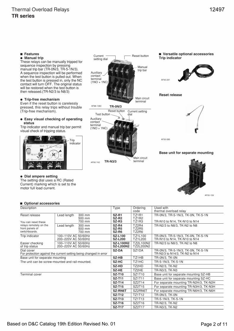
■ Selection guide/Standard type
On-contactor 3-element TR-0N/3 TR-5-1N/3 TR-N2/3 TR-N3/3mounting (TR13DW) (TR20DW) (TR35BDW) (TR65BDW)
2-element TR-0N TR-5-1N TR-N2 TR-N3(TR13NW) (TR20NW) (TR35BNW) (TR65BNW)
Separate 3-element TR-0NH/3 TR-5-1NH/3 TR-N2H/3 TR-N3H/3mounting (TR13DH) (TR20DH) (TR35BDH) (TR65BDW)
2-element TR-0NH TR-5-1NH TR-N2H TR-N3H(TR13NH) (TR20NH) (TR35BNH) (TR65BNW)
Contactor to be combined SC-03 SC-0 SC-4-0 SC-4-1 SC-N1 SC-N2 SC-N2S SC-N3SC-05 SC-5-1
Ampere Code A 0.1 – 0.15 0.1 – 0.15 0.1 – 0.15 0.1 – 0.15setting range B 0.13 – 0.2 0.13 – 0.2 0.13 – 0.2 0.13 – 0.2(A) C 0.15 – 0.24 0.15 – 0.24 0.15 – 0.24 0.15 – 0.24
D 0.2 – 0.3 0.2 – 0.3 0.2 – 0.3 0.2 – 0.3E 0.24 – 0.36 0.24 – 0.36 0.24 – 0.36 0.24 – 0.36F 0.3 – 0.45 0.3 – 0.45 0.3 – 0.45 0.3 – 0.45G 0.36 – 0.54 0.36 – 0.54 0.36 – 0.54 0.36 – 0.54H 0.48 – 0.72 0.48 – 0.72 0.48 – 0.72 0.48 – 0.72J 0.64 – 0.96 0.64 – 0.96 0.64 – 0.96 0.64 – 0.96K 0.8 – 1.2 0.8 – 1.2 0.8 – 1.2 0.8 – 1.2L 0.95 – 1.45 0.95 – 1.45 0.95 – 1.45 0.95 – 1.45M 1.4 – 2.2 1.4 – 2.2 1.4 – 2.2 1.4 – 2.2N 1.7 – 2.6 1.7 – 2.6 1.7 – 2.6 1.7 – 2.6P 2.2 – 3.4 2.2 – 3.4 2.2 – 3.4 2.2 – 3.4R 2.8 – 4.2 2.8 – 4.2 2.8 – 4.2 2.8 – 4.2S 4 – 6 4 – 6 4 – 6 4 – 6 4 – 6 4 – 6T 5 – 8 5 – 8 5 – 8 5 – 8 5 – 8 5 – 8U 6 – 9 6 – 9 6 – 9 6 – 9 6 – 9 6 – 9V 7 – 11 7 – 11 7 – 11 7 – 11 7 – 11 7 – 11 7 – 11 7 – 11W 9 – 13 9 – 13 9 – 13 9 – 13 9 – 13 9 – 13 9 – 13X 12 – 18 12 – 18 12 – 18 12 – 18 12 – 18 12 – 18Q 16 – 22B 18 – 26 18 – 26 18 – 26 18 – 26E 24 – 36 24 – 36 24 – 36 24 – 36F 28 – 40 28 – 40I 32 – 42G 34 – 50 34 – 50J 45 – 65 45 – 65O 48 – 68L 53 – 80*M 65 – 95*I 85 – 105*
Specify the settingrange code whenordering.
On-contactor 3-element TR-N5/3 TR-N6/3 TR-N7/3 TR-N8/3 TR-N10/3 TR-N12/3 TR-N14/3mounting (TR80BDW) (TR1CBDW) (TR1FBDW) (TR1JBDW) (TR2CBDW) (TR4ABDW) (TR8ABDW)
2-element TR-N5 TR-N6 TR-N7 TR-N8 TR-N10 TR-N12 TR-N14(TR80BNW) (TR1CBNW) (TR1FBNW) (TR1JBNW) (TR2CBNW) (TR4ABNW) (TR8ABNW)
Separate 3-element – TR-N6H/3 – – TR-N10H/3 TR-N12H/3 TR-N14H/3mounting (TR1CBDW) (TR2CBDH) (TR4ABDH) (TR8ABDH)
2-element – TR-N6H – – TR-N10H TR-N12H TR-N14H(TR1CBNW) (TR2CBNH) (TR4ABNH) (TR8ABNH)
Contactor to be combined SC-N4 SC-N5 SC-N6 SC-N7 SC-N8 SC-N10 SC-N11 SC-N12 SC-N14
Ampere Code B 18 – 26 18 – 26setting range E 24 – 36 24 – 36(A) F 28 – 40 28 – 40
G 34 – 50 34 – 50J 45 – 65 45 – 65 45 – 65 45 – 65L 53 – 80 53 – 80 53 – 80 53 – 80M 65 – 95 65 – 95 65 – 95 65 – 95I 85 – 105N 85 – 125 85 – 125 85 – 125 85 – 125P 110 – 160* 110 – 160 110 – 160 110 – 160 110 – 160 110 – 160R 125 – 185 125 – 185 125 – 185 125 – 185S 160 – 240 160 – 240 160 – 240T 200 – 300 200 – 300U 240 – 360 240 – 360V 300 – 450 300 – 450W 400 – 600
Notes: • TR-N10/3 to N14/3 types are provided with CTs.• Max. setting ranges of these starters are as shown in the table on the right.• When ordering the thermal overload relays for starter use,
select the applicable setting range.Motor starter Maximum applicable heater range (A)
200–240V 380–440V
SW-03/3H 7–11 6–9SW-4-0/3H 12–18 12–18SW-N1/3H 24–36 24–36SW-N2S/3H 34–50 34–50SW-N4/3H 53–80 53–80SW-N6/3H 85–125 85–125
( ): Basic ordering code (When ordering phase-loss protective type,enter the version code E instead of D)
* : Separate mounting only
Thermal Overload RelaysTR seriesStandard type
12497
Based on D&C Catalog 19th Edition Revised No. 01 Page 3 of 11

■ Selection guide/Long time operating type
( ): Basic ordering code* : Separate mounting only
On-contactor 3-elementmounting
2-element
Separate 3-elementmounting
2-element
Contactor to be combined
Ampere Code Bsetting range E(A) F
GJLM
NPRSTUV
W
Specify the settingrange code whenordering.
Thermal Overload RelaysTR seriesLong time operating type
On-contactor 3-element – – TR-N2L/3 TR-N3L/3mounting (TR35BFW) (TR65BFW)
2-element – – TR-N2L TR-N3L(TR35BLW) (TR65BLW)
Separate 3-element TR-0NLH/3 TR-5-1NLH/3 TR-N2LH/3 TR-N3LH/3mounting (TR13FH) (TR20FH) (TR35BFH) (TR65BFH)
2-element TR-0NLH TR-5-1NLH TR-N2LH TR-N3LH(TR13LH) (TR20LH) (TR35BLH) (TR65BLH)
Contactor to be combined SC-03 SC-0 SC-4-0 SC-4-1 SC-N1 SC-N2 SC-N2S SC-N3SC-05 SC-5-1
Ampere Code L 0.95 – 1.45 0.95 – 1.45 0.95 – 1.45 0.95 – 1.45setting range M 1.4 – 2.2 1.4 – 2.2 1.4 – 2.2 1.4 – 2.2(A) N 1.7 – 2.6 1.7 – 2.6 1.7 – 2.6 1.7 – 2.6
P 2.2 – 3.4 2.2 – 3.4 2.2 – 3.4 2.2 – 3.4R 2.8 – 4.2 2.8 – 4.2 2.8 – 4.2 2.8 – 4.2
S 4 – 6 4 – 6 4 – 6 4 – 6 4 – 6 4 – 6T 5 – 8 5 – 8 5 – 8 5 – 8 5 – 8 5 – 8U 6 – 9 6 – 9 6 – 9 6 – 9 6 – 9 6 – 9V 7 – 11 7 – 11 7 – 11 7 – 11 7 – 11 7 – 11 7 – 11 7 – 11W 9 – 13 9 – 13 9 – 13 9 – 13 9 – 13 9 – 13 9 – 13
X 12 – 18 12 – 18 12 – 18 12 – 18 12 – 18 12 – 18B 18 – 26 18 – 26 18 – 26 18 – 26E 24 – 36 24 – 36 24 – 36F 28 – 40 28 – 40G 34 – 50 34 – 50J 45 – 65L 53 – 80*M 65 – 95*
Notes:Maximum setting ranges of the these starters are as shown in the table below.Select the applicable setting range when ordering the thermal overload relays for starter use.
Motor starter Maximum applicable heater range (A)200–240V 380–440V
SW-03/2L, 3L 7–11 6–9SW-N2S/2L, 3L 34–50 34–50SW-N4/2L, 3L 53–80 53–80SW-N6/2L, 3L 85–125 85–125
TR-N5L/3 TR-N6L/3 TR-N7L/3 TR-N10L/3 TR-N12L/3 TR-N14L/3(TR80BFW) (TR1CBFW) (TR1FBFW) (TR2CBFW) (TR4ABFW) (TR8ABFW)TR-N5L TR-N6L TR-N7L TR-N10L TR-N12L TR-N14L(TR80BLW) (TR1CBLW) (TR1FBLW) (TR2CBLW) (TR4ABLW) (TR8ABLW)
– TR-N6LH/3 – TR-N10LH/3 TR-N12LH/3 TR-N14LH/3(TR1CBFH) (TR2CBFH) (TR4ABFH) (TR8ABFH)
– TR-N6LH – TR-N10LH TR-N12LH TR-N14LH(TR1CBLH) (TR2CBLH) (TR4ABLH) (TR8ABLH)
SC-N4 SC-N5 SC-N6 SC-N7 SC-N8 SC-N10 SC-N11 SC-N12 SC-N14
18 – 26 18 – 2624 – 36 24 – 3628 – 40 28 – 4034 – 50 34 – 5045 – 65 45 – 65 45 – 65 45 – 6553 – 80 53 – 80 53 – 80 53 – 80
65 – 95 65 – 95 65 – 95
85 – 125 85 – 125 85 – 125 85 – 125110 – 160* 110 – 160 110 – 160 110 – 160 110 – 160 110 – 160
125 – 185 125 – 185 125 – 185 125 – 185160 – 240 160 – 240 160 – 240
200 – 300 200 – 300240 – 360 240 – 360300 – 450 300 – 450
400 – 600
12497
Based on D&C Catalog 19th Edition Revised No. 01 Page 4 of 11
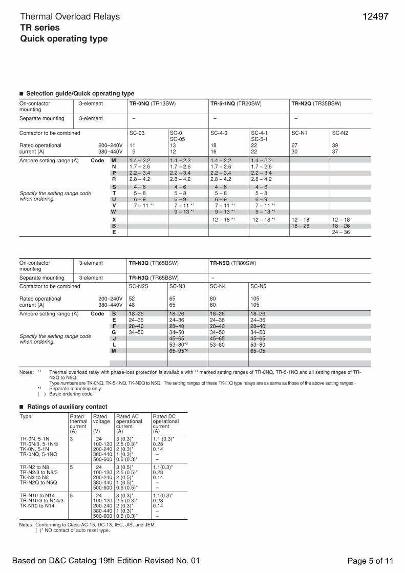
Type Rated Rated Rated AC Rated DCthermal voltage operational operationalcurrent current current(A) (V) (A) (A)
TR-0N, 5-1N 3 24 3 (0.3)* 1.1 (0.3)*TR-0N/3, 5-1N/3 100-120 2.5 (0.3)* 0.28TK-0N, 5-1N 200-240 2 (0.3)* 0.14TR-0NQ, 5-1NQ 380-440 1 (0.3)* –
500-600 0.6 (0.3)* –
TR-N2 to N8 5 24 3 (0.5)* 1.1(0.3)*TR-N2/3 to N8/3 100-120 2.5 (0.5)* 0.28TK-N2 to N8 200-240 2 (0.5)* 0.14TR-N2Q to N5Q 380-440 1 (0.5)* –
500-600 0.6 (0.5)* –
TR-N10 to N14 5 24 3 (0.3)* 1.1(0.3)*TR-N10/3 to N14/3 100-120 2.5 (0.3)* 0.28TK-N10 to N14 200-240 2 (0.3)* 0.14
380-440 1 (0.3)* –500-600 0.6 (0.3)* –
TR-N3Q (TR65BSW) TR-N5Q (TR80SW)
TR-N3Q (TR65BSW) –
SC-N2S SC-N3 SC-N4 SC-N5
52 65 80 10548 65 80 105
18–26 18–26 18–26 18–2624–36 24–36 24–36 24–3628–40 28–40 28–40 28–4034–50 34–50 34–50 34–50
45–65 45–65 45–6553–80*2 53–80 53–8065–95*2 65–95
On-contactor 3-elementmounting
Separate mounting 3-element
Contactor to be combined
Rated operational 200–240Vcurrent (A) 380–440V
Ampere setting range (A) Code BEFGJLM
■ Selection guide/Quick operating type
Specify the setting range codewhen ordering.
Specify the setting range codewhen ordering.
Notes: *1 Thermal overload relay with phase-loss protection is available with *1 marked setting ranges of TR-0NQ, TR-5-1NQ and all setting ranges of TR-N2Q to N5Q.Type numbers are TK-0NQ, TK-5-1NQ, TK-N2Q to N5Q. The setting ranges of these TK-�Q type relays are as same as those of the above setting ranges.
*2 Separate mounting only.( ) Basic ordering code
On-contactor 3-elementmounting
Separate mounting 3-element
Contactor to be combined
Rated operational 200–240Vcurrent (A) 380–440V
Ampere setting range (A) Code MNPR
STUVW
XBE
TR-0NQ (TR13SW) TR-5-1NQ (TR20SW) TR-N2Q (TR35BSW)
– – –
SC-03 SC-0 SC-4-0 SC-4-1 SC-N1 SC-N2SC-05 SC-5-1
11 13 18 22 27 39 9 12 16 22 30 37
1.4 – 2.2 1.4 – 2.2 1.4 – 2.2 1.4 – 2.21.7 – 2.6 1.7 – 2.6 1.7 – 2.6 1.7 – 2.62.2 – 3.4 2.2 – 3.4 2.2 – 3.4 2.2 – 3.42.8 – 4.2 2.8 – 4.2 2.8 – 4.2 2.8 – 4.2
4 – 6 4 – 6 4 – 6 4 – 6 5 – 8 5 – 8 5 – 8 5 – 8 6 – 9 6 – 9 6 – 9 6 – 9 7 – 11 *1 7 – 11 *1 7 – 11 *1 7 – 11 *1
9 – 13 *1 9 – 13 *1 9 – 13 *1
12 – 18 *1 12 – 18 *1 12 – 18 12 – 1818 – 26 18 – 26
24 – 36
■ Ratings of auxiliary contact
Notes: Conforming to Class AC-15, DC-13, IEC, JIS, and JEM.( )* NO contact of auto reset type.
Thermal Overload RelaysTR seriesQuick operating type
12497
Based on D&C Catalog 19th Edition Revised No. 01 Page 5 of 11
Thermal Overload RelaysTR series
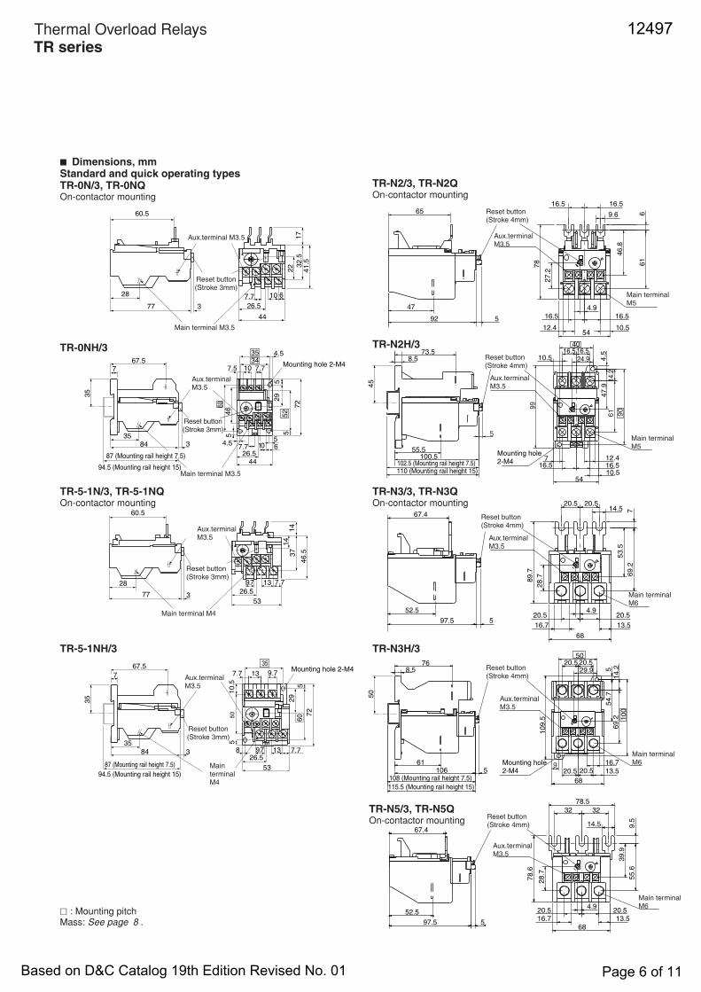
■ Dimensions, mmStandard and quick operating typesTR-0N/3, TR-0NQOn-contactor mounting
TR-0NH/3
TR-N2/3, TR-N2QOn-contactor mounting
TR-5-1N/3, TR-5-1NQOn-contactor mounting
TR-N3/3, TR-N3QOn-contactor mounting
TR-5-1NH/3
TR-N5/3, TR-N5QOn-contactor mounting
TR-N3H/3
TR-N2H/3
60.5
28
77 31
72
2 32
.54
1.5
7.7
26.5
44
10 6
35
67.5
84 3
5
4.5
26.544
7.7 65
5
72
4.5
7.5 10 7.7
29
5
46
Mounting hole 2-M4
Mounting hole 2-M4
Mounting hole 2-M4
7
60
3435
52
60.5
28
77 3
14
14
37
46
.5
9.7
26.5
53
13 7.7
35
67.5
84 3
5
826.5
53
7.713
72
137.7
5
50
7 9.7
29
9.7
35
60
10
.5
12.4
4.9
9.6 6
16.516.5
54
92
47
65
5 16.516.5
61
78
27
.2
46
.8
10.5
73.5
61
16.5
90
40
14
.2
16.5
4.510.58.5
7
5410.516.516.5
24.9
47
.9
12.4100.555.5
5
99
13.516.7
4.9
14.5
28
.7
67.4
20.520.5
20.520.5
89
.7
7
53
.5
69
.2
597.5
52.5
68
16.713.5106 5 20.520.5
20.520.5
10
0
54
.7
29.9
61
8.576
68
10
9.5
5
50
69
.21
4.2
4.9
14.5
28
.7
78.5
13.516.7
78
.6
39
.9
55
.6
3232
9.5
20.520.5
68
52.5
67.4
97.5 5
9
Aux.terminal M3.5 Aux.terminal M3.5
Aux.terminal M3.5
Aux.terminal M3.5
Aux.terminal M3.5
Aux.terminal M3.5
Aux.terminal M3.5
Reset button(Stroke 3mm)
Reset button(Stroke 4mm)
Reset button(Stroke 4mm)
Reset button(Stroke 4mm)
Reset button(Stroke 4mm)
Reset button(Stroke 4mm)
Reset button(Stroke 3mm)
Reset button(Stroke 3mm)
Main terminal M3.5
Main terminal M5
Main terminal M5
Main terminal M6
Main terminal M6
Main terminal M3.5
Main terminal M4
87 (Mounting rail height 7.5)
94.5 (Mounting rail height 15)102.5 (Mounting rail height 7.5)110 (Mounting rail height 15)
Aux.terminal M3.5
Main terminal M6
108 (Mounting rail height 7.5)
115.5 (Mounting rail height 15)
Mounting hole 2-M4Aux.terminal M3.5
Reset button(Stroke 3mm)
Main terminal M4
87 (Mounting rail height 7.5)
94.5 (Mounting rail height 15)
10
35
35
45
50
� : Mounting pitchMass: See page 8 .
12497
Based on D&C Catalog 19th Edition Revised No. 01 Page 6 of 11
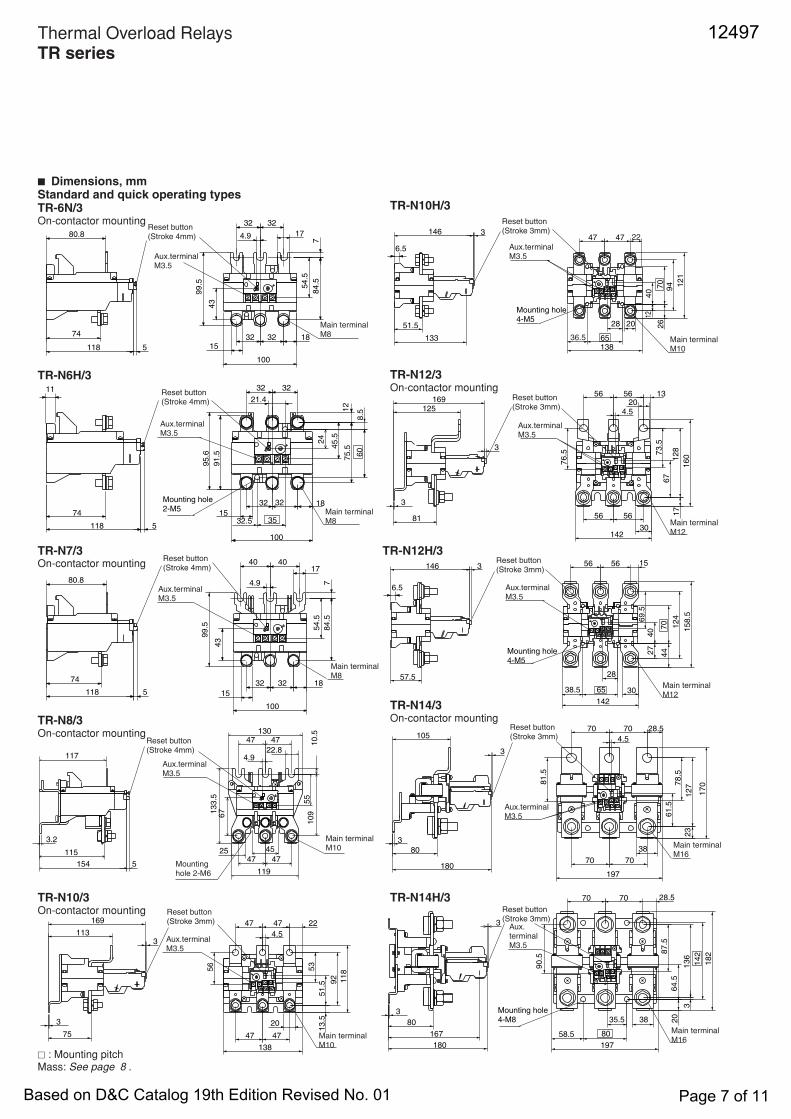
■ Dimensions, mmStandard and quick operating typesTR-6N/3On-contactor mounting
TR-N10H/3
TR-N6H/3
133
94
40
4747
12
1
262851.5
12
20
146
70
65138
3
4.5
56
20
67
13
16
0
17
76
.5
169125
3
3
73
.5
5656
12
8
5681
14230
28
4427
40
69
.5
15
8.5
70 12
4
5656146
30
142
65
3
57.57
8.5
18070
12
7
7070105
38
17
0
80
4.5
23
197
3
3
28.5
61
.5
81
.5
70
90
.5
87
.5
20
64
.5
180
80
35.5
31
36
7070
38
14
2
18
2
167
197
3
3
80
36.5
22
15
38.5
28.5
58.5
Mounting hole 4-M5
Aux.terminal M3.5
Reset button(Stroke 3mm)
Main terminal M10
Aux.terminal M3.5
Aux.terminal M3.5
Reset button(Stroke 3mm)
Main terminal M12
Mounting hole 4-M5
Reset button(Stroke 3mm)
Main terminal M12
Aux.terminal M3.5
Reset button(Stroke 3mm)
Main terminal M16
Mounting hole 4-M8
Aux.terminal M3.5
Reset button(Stroke 3mm)
Main terminal M16
6.5
6.5
74
80.8
11
118 5
4.9 17
43
1815
3232
54.5
84.5
99.5
7
3232
100
74
118 5
24
21.4
60
35
45.5
12
75.5
91.5
95.6
3232
18
1532.5
3232
100
8.5
4.9
17
43
18
15
99.5 54.5
84.5
4040
7
3232
100
74
80.8
118 5
118
47
13.5
4.5
75
20
51.5
53
47
92
47
47
3
169
3113
138
22
56
Mounting hole 2-M5
Aux.terminal M3.5
Aux.terminal M3.5
Aux.terminal M3.5
Aux.terminal M3.5
Reset button(Stroke 4mm)
Reset button(Stroke 3mm)
Reset button(Stroke 4mm)
Reset button(Stroke 4mm)
Main terminal M8
Main terminal M10
Main terminal M8
Main terminal M8
45
3.2
130
67
22.8
4747
4.9
119
254747
10.5
154
115
5
117
133.5
109
55
Reset button(Stroke 4mm)
Aux.terminalM3.5
Mountinghole 2-M6
Main terminalM10
TR-N8/3On-contactor mounting
TR-N7/3On-contactor mounting
TR-N10/3On-contactor mounting
TR-N12/3On-contactor mounting
TR-N12H/3
TR-N14/3On-contactor mounting
TR-N14H/3
Thermal Overload RelaysTR series
� : Mounting pitchMass: See page 8 .
12497
Based on D&C Catalog 19th Edition Revised No. 01 Page 7 of 11
1
72
39.5
88.5 3
44
35 4.5
10 7.77.5
10
0
90
54
54
72
0
107.7 6
4922.5
83
1
72
39.5
88.5 3
10
0
90
54
45
0
9.7 8
35
18.588
8 13 10
539
Mounting hole 4-M4
Mounting hole 4-M4
Aux.terminal M3.5
Aux.terminal M3.5
Reset button(Stroke 3mm)
Reset button(Stroke 3mm)
Main terminal M4
Main terminal M3.5
13
4728
M5
12
4.5
6592
54
.5
68
8
46.5
51
9.616.516.5
12835
5
27
4.91635(2/T1,6/T3)
14
46.5
73.5
61.5
55.5
128
27
28
5100.5
35
16.5
90
40
16.5
4.510.5
59.5
42.5
137
35
88
25
47.5
12
8.5
(2/T1,6/T3)
M5Main terminal
Main terminal
(For 2 element type 4/T2)
(For 3 element type 4/T2)
(For 2 element type 4/T2)
(For 3 element type 4/T2)
Mounting hole2-M4
Reset button(Stroke 4mm)
Reset button(Stroke 4mm)
Aux. terminalM3.5
Aux. terminalM3.5
53
16
45
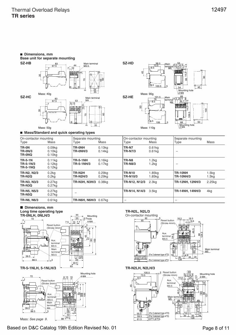
■ Mass/Standard and quick operating types
■ Dimensions, mmLong time operating typeTR-0NLH, 0NLH/3
TR-N2L, N2L/3On-contactor mounting
TR-5-1NLH, 5-1NLH/3 TR-N2LH, N2LH/3
Mass: 40g
Mass: 50g
Mass: 90g
Mass: 110g
SZ-HB
SZ-HC
SZ-HD
SZ-HE
8367.5
7
44107
Main terminal M3.5
9
70
2
52 60
3534
35
Main terminal M4
8367.5
7
53138
10
.57
02
60
35
35
L35L23L11
99 9
0
4054100.5
16.5
8.5
14
.2
54
7 4.5
5
98.573.5
8.5
2-M4Mounting hole
M5
Main terminal
12.410.5
45
Main terminal
1 L1 3 L2 5 L3
68
20.576
10
0
50
689
51
09
.51
4.2
101.5
8.5
8.5106 5
16.7M6
2-M4Mounting hole
13.5
50
■ Dimensions, mmBase unit for separate mounting
Thermal Overload RelaysTR series
On-contactor mounting Separate mounting On-contactor mounting Separate mountingType Mass Type Mass Type Mass Type Mass
TR-0N 0.09kg TR-0NH 0.13kg TR-N7 0.61kgTR-0N/3 0.10kg TR-0NH/3 0.14kg TR-N7/3 0.61kg –TR-0NQ 0.10kg
TR-5-1N 0.11kg TR-5-1NH 0.16kg TR-N8 1.2kgTR-5-1N/3 0.12kg TR-5-1NH/3 0.17kg TR-N8/3 1.2kg –TR-5-1NQ 0.12kg
TR-N2, N2/3 0.2kg TR-N2H 0.29kg TR-N10 1.85kg TR-10NH 1.5kgTR-N2Q 0.2kg TR-N2H/3 0.29kg TR-N10/3 1.85kg TR-10NH/3 1.5kg
TR-N3, N3/3 0.27kg TR-N3H, N3H/3 0.38kg TR-N12, N12/3 2.3kg TR-12NH, 12NH/3 2.25kgTR-N3Q 0.27kg
TR-N5, N5/3 0.27kg – TR-N14, N14/3 3.5kg TR-14NH, 14NH/3 4kgTR-N5Q 0.27kg
TR-N6, N6/3 0.61kg TR-N6H, N6H/3 0.67kg – –
Mass: See page 9.
12497
Based on D&C Catalog 19th Edition Revised No. 01 Page 8 of 11
M8
17
3232
74
68
100
18
193232
144.5
54.5
109.5
74.9
25
5
80
80.8118
32
100.5
8.5
141
12
24
60
45.5
8
32
15
3232
25
5
74
1880
100
118
74M8
M8
40 4054.5
109.5
74
68
100
165
165
1819
3232
717
144.5
4.9
5
25
118
80
80.8
19
22.5
3532.5
165
Main terminal
Main terminal
Main terminal
(For 2 element type 4/T2)
(For 2 element type 4/T2)
(For 2 element type 4/T2)
Mounting hole2-M5
Reset button(Stroke 4mm)
Reset button(Stroke 4mm)
Reset button(Stroke 4mm)
Aux. terminalM3.5
Aux. terminalM3.5
Aux. terminalM3.5
Approx.
Approx.
Approx.
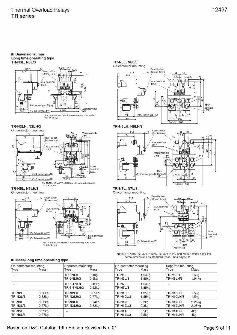
TR-N6L, N6L/3On-contactor mounting
■ Dimensions, mmLong time operating typeTR-N3L, N3L/3
TR-N6LH, N6LH/3
Note: TR-N10L, N10LH, N12NL, N12LH, N14L and N14LH types have thesame dimensions as standard types. See pages 8.
■ Mass/Long time operating type
On-contactor mounting Separate mounting On-contactor mounting Separate mountingType Mass Type Mass Type Mass Type Mass
– TR-0NLH 0.4kg TR-N6L 1.54kg TR-N6LH 1.6kgTR-0NLH/3 0.5kg TR-N6L/3 1.85kg TR-N6LH/3 1.91kg
– TR-5-1NLH 0.42kg TR-N7L 1.54kg –TR-5-1NLH/3 0.52kg TR-N7L/3 1.85kg
TR-N2L 0.56kg TR-N2LH 0.65kg TR-N10L 1.85kg TR-N10LH 1.5kgTR-N2L/3 0.68kg TR-N2LH/3 0.77kg TR-N10L/3 1.85kg TR-N10LH/3 1.5kg
TR-N3L 0.63kg TR-N3LH 0.74kg TR-N12L 2.3kg TR-N12LH 2.25kgTR-N3L/3 0.77kg TR-N3LH/3 0.88kg TR-N12L/3 2.3kg TR-N12LH/3 2.25kg
TR-N5L 0.63kg – TR-N14L 3.5kg TR-N14LH 4kgTR-N5L/3 0.77kg TR-N14L/3 3.5kg TR-N14LH/3 4kg
28
M6Main terminal
Main terminal
Main terminal
97.5 5 20.5
52.5
(For 3 element type 4/T2)
(For 2 element type 4/T2)
(For 2 element type 4/T2)
(For 3 element type 4/T2)
(For 3 element type 4/T2)
41
*1 140
14.5
53.5
798.5
*2 1
34
58
516
20.5
41
30
67.4
56.5
76
2844
20.520.5
100
54.7
30
6569
8.5
5
30
5
50
41 41
*2 1
46
*1 140
61
99
106
14
53.5
Mounting hole2-M4
M6
M6
29.5
32
60.5
123
52.5 41140
40
85
9.5
58
516
32
41
14.567.4
56.5
97.5 5
For TR-N3L/3 and TR-N3L type with setting of 45 to 65A*1: 149, *2: 137
28
Reset button(Stroke 4mm)
Reset button(Stroke 4mm)
Reset button(Stroke 4mm)
Aux. terminalM3.5
Aux. terminalM3.5
Aux. terminalM3.5
*2
For TR-N3LH/3 and TR-N3LH type with setting of 45 to 65A*1: :149, *2: 149
For TR-N3LH/3 and TR-N3LH type with setting of 45 to 65A*1: 149, *2: 126
*1
(For 2 element type 4/T2)
60.5
16
50
TR-N7L, N7L/3On-contactor mounting
TR-N5L, N5LH/3On-contactor mounting
Thermal Overload RelaysTR series
TR-N3LH, N3LH/3On-contactor mounting
12497
Based on D&C Catalog 19th Edition Revised No. 01 Page 9 of 11

Thermal Overload RelaysTR series
0.8 1 1.5 2 3 4 5 6 7 8 9 10 15
1
0.8
0.6
0.4
10
8
6
4
3
2
30
20
2
3
5
810
20
30
50
1
0.8
0.6
0.4
10
8
6
4
3
2
40
30
20
2
3
5
810
20
30
50
0.8 1 1.5 2 3 4 5 6 7 8 9 10 15
1
0.8
0.6
0.4
10
8
6
4
3
2
4030
20
2
3
5
810
20
30
50
0.8 1 1.5 2 3 4 5 6 7 8 9 10 15
Multiple of current setting XIn (A) Multiple of current setting XIn (A) Multiple of current setting XIn (A)
60
Min
ute
Trippin
g tim
e
0.3
Second
Min
ute
Trippin
g tim
e
Second
Min
ute
Trippin
g tim
e
Second
0.3
40
60
0.3
60
TR-N2 to N8TR-N2/3 to N8/3TR-N2H, N3H, N6HTR-N2H/3, N3H/3, N6H/3
2-element 3-element 2-element(with CTs)
3-element(with CTs)
■ Characteristic curves● Standard typeTR-0N, 5-1N,TR-0N/3, 5-1N/3,TR-0NH, 5-1NH,TR-0NH/3, 5-1NH/3
TR-N10 to N14,TR-N10/3 to N14/3,TR-N10H to N14HTR-N10H/3 to N14H/3
TR-N10 to N14TR-N10/3 to N14/3TR-N10H to N14HTR-N10H/3 to N14H/3
(NO) (NC)
(NO) (NC)
97 95
98 96 2/T1 4/T2 6/T3
(NO) (NC)
(NO) (NC)
97 95
98 96 2/T1 4/T2 6/T3
1/L1 3/L2 5/L3 1/L1 3/L2 5/L3 1/L1 3/L2 5/L397 95
(NO) (NC)
(NO) (NC)98 96 2/T1 4/T2 6/T3
(NO) (NC)
(NO) (NC)
97 95
98 96 2/T1 4/T2 6/T3
1/L1 3/L2 5/L3
These curves show cold starting characteristics.
SZ-DA
2
14
SZ-R1SZ-R2SZ-R3
8
6.5
16
12
9
SZ-R4SZ-R5SZ-R6
12 8
Locking nutM10
Locking nutM10
Resetbutton
Resetbutton
L
L
23.5
6.5
Panel drilling 10.5 to 11
SZ-L100SZ-L200
SZ-L100N2SZ-L200N2
113.5
26
Approx.4408 3
Approx.4508
11
26
Approx.250
Panel drilling 10.5 to 11
9
Type
SZ-R1
SZ-R1
SZ-R1
L
300
500
700
Type
SZ-R4
SZ-R5
SZ-R6
L
300
500
700
Approx.140
■ Dimensions, mmOptional accessoriesTrip indicator Reset release button
Dial cover
■ Wiring diagrams● Standard typeTR-0N to N8TR-0N/3 to N8/3TR-0NH, 5-1NH, N2H, N3H, N6HTR-0NH/3, 5-1NH/3, N2H/3, N3H/3, N6H/3
12497
Based on D&C Catalog 19th Edition Revised No. 01 Page 10 of 11

■ Characteristic curves These curves show cold starting characteristics● Long time operating type (When setting at the center dial current)TR-0NL, 5-1NLTR-0NL/3, 5-1NL/3TR-0NLH, 5-1NLHTR-0NLH/3, 5-1NLH/3
TR-N2L to N7LTR-N2L/3 to N7L/3TR-N2LH, N3LH, N6LHTR-N2LH/3, N3LH/3, N6LH/3
TR-N10L to N14LTR-N10L/3 to N14L/3TR-N10LH to N14LHTR-N10LH/3 to N14LH/3
● Quick operating typeTR-0NQ, 5-1NQ
● Quick operating typeTR-0NQ, 5-1NQTR-N2Q, N3Q, N5Q
3-element
0.8 1 1.5 2 3 4 5 6 7 8 9 10 15
1
0.8
0.6
0.4
10
8
6
4
3
2
4030
20
2
3
5
810
20
30
50
80
0.8 1 1.5 2 3 4 5 6 7 8 9 10 15
1
0.8
0.6
0.4
10
8
6
4
3
2
4030
20
2
3
5
810
20
30
50
0.8 1 1.5 2 3 4 5 6 7 8 9 10 15
Multiple of current setting
1
0.8
0.6
0.4
10
8
6
4
3
2
4030
20
2
3
5
810
20
30
50
xIn (A) Multiple of current setting xIn (A) Multiple of current setting xIn (A)
60
0.3
Trip
pin
g tim
e
Min
ute
Se
con
d
Trip
pin
g tim
e
Min
ute
Se
con
d
Trip
pin
g tim
e
Min
ute
Se
con
d
0.3
60
0.3
60
0.8 1 1.5 2 3 4 5 6 7 8 9 10 15
1
0.8
0.6
0.4
10
8
6
4
3
2
4030
20
2
3
5
810
20
30
50
0.8 1 1.5 2 3 4 5 6 7 8 9 10 15
1
0.8
0.6
0.4
10
8
6
4
3
2
4030
20
2
3
5
810
20
30
50
Multiple of current setting xIn (A) Multiple of current setting xIn (A)
Trip
pin
g t
ime
Min
ute
Se
con
d
Trip
pin
g t
ime
Min
ute
Se
con
d
0.3
60
0.3
60
TR-N2Q, N3Q, N5Q
(NO) (NC)
(NO) (NC)
97 95
98 96 2/T1 4/T2 6/T3
1/L1 3/L2 5/L3
Thermal Overload RelaysTR series
■ Wiring diagrams● Long time operating typeTR-0NL to N7LTR-0NL/3 to N7L/3TR-0NLH, 5-1NLH, N2LH, N3LH, N6LHTR-0NLH/3, 5-1NLH/3, N2LH/3, N3LH/3, N6LH/3
TR-N10L to N14LTR-N10L/3 to N14L/3TR-N10LH to N14LHTR-N10LH/3 to N14LH/32-element(with CTs)
3-element(with CTs)
3-element2-element
97 95(NO) (NC)
(NO) (NC)
(NO) (NC)
(NO) (NC)
98 96
97 95
98 96 2/T1 4/T2 6/T3
1/L1 3/L2 5/L3
2/T1 4/T2 6/T3
1/L1 3/L2 5/L3(NO) (NC)
(NO) (NC)
97 95
98 96 2/T1 4/T2 6/T3
1/L1 3/L2 5/L3 1/L1 3/L2 5/L3(NO) (NC)
(NO) (NC)
97 95
98 96 2/T1 4/T2 6/T3
12497
Based on D&C Catalog 19th Edition Revised No. 01 Page 11 of 11