Embed Size (px)
Citation preview
CP 311
S-DIAS CPU Module
Date of creation: 22.06.2016 Version date: 26.11.2019 Article number: 20-004-311-E
Publisher: SIGMATEK GmbH & Co KG
A-5112 Lamprechtshausen
Tel.: +43/6274/4321
Fax: +43/6274/4321-18
Email: [email protected]
WWW.SIGMATEK-AUTOMATION.COM
Copyright © 2016
SIGMATEK GmbH & Co KG
Translation from German
All rights reserved. No part of this work may be reproduced, edited using an electronic system, duplicated or
distributed in any form (print, photocopy, microfilm or in any other process) without the express permission.
We reserve the right to make changes in the content without notice. The SIGMATEK GmbH & Co KG is not
responsible for technical or printing errors in the handbook and assumes no responsibility for damages that occur
through use of this handbook.
S-DIAS CPU MODULE CP 311
26.11.2019 Page 1
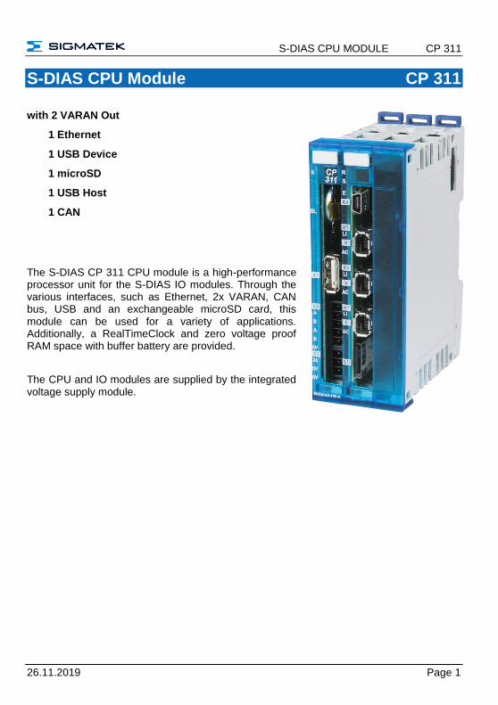
S-DIAS CPU Module CP 311
with 2 VARAN Out
1 Ethernet
1 USB Device
1 microSD
1 USB Host
1 CAN
The S-DIAS CP 311 CPU module is a high-performance processor unit for the S-DIAS IO modules. Through the various interfaces, such as Ethernet, 2x VARAN, CAN bus, USB and an exchangeable microSD card, this module can be used for a variety of applications. Additionally, a RealTimeClock and zero voltage proof RAM space with buffer battery are provided.
The CPU and IO modules are supplied by the integrated voltage supply module.
CP 311 S-DIAS CPU MODULE
Page 2 26.11.2019
Contents
1 Technical Data ........................................................................ 5
1.1 Performance Data ......................................................................... 5
1.2 Standard Configuration ................................................................ 6
1.3 Electrical Requirements ............................................................... 7
1.3.1 Module Supply (Input) ......................................................................... 7
1.3.2 S-DIAS Bus Supply (Output) ............................................................... 7
1.4 Miscellaneous ............................................................................... 9
1.5 Environmental Conditions ........................................................... 9
2 Mechanical Dimensions ........................................................10
3 Connector Layout ..................................................................11
3.1 Status LEDs Interface Part......................................................... 12
3.2 Status LEDs Supply Part ............................................................ 12
3.3 Connectors .................................................................................. 13
3.4 Applicable Connector Cables .................................................... 15
3.5 Applicable Connectors ............................................................... 16
3.6 Label Field ................................................................................... 17
4 CAN Bus Setup ......................................................................18
4.1 CAN Bus Station Number .......................................................... 18
4.2 Number of CAN Bus Participants ............................................. 18
4.3 CAN Bus Data Transfer Rate ..................................................... 18
4.4 CAN Bus Termination ................................................................. 19
S-DIAS CPU MODULE CP 311
26.11.2019 Page 3
5 Buffer Battery ........................................................................ 20
6 Wiring Guidelines .................................................................. 21
7 Storage Media ........................................................................ 22
8 Process Diagram ................................................................... 23
9 Status and Error Messages .................................................. 24
10 Application Exceptions ......................................................... 32
10.1 The File System Does Not Support Safe Writing via SRAM ... 32
10.2 Data Breakpoint .......................................................................... 32
11 Wiring Guidelines .................................................................. 33
11.1 Shielding ...................................................................................... 34
11.2 ESD Protection ............................................................................ 34
12 Strain Relief ........................................................................... 35
13 Recommended Shielding for VARAN .................................. 36
13.1 Wiring from the Control Cabinet to an External VARAN component ................................................................................... 37
13.2 Wiring Outside of the Control Cabinet ..................................... 38
13.3 Shielding for Wiring Within the Control Cabinet ..................... 39
13.4 Connecting Noise Generating Components ............................ 40
13.5 Shielding Between Two Control Cabinets ............................... 41
14 Working with and on the CP 311 .......................................... 41
CP 311 S-DIAS CPU MODULE
Page 4 26.11.2019
15 Mounting .................................................................................42
S-DIAS CPU MODULE CP 311
26.11.2019 Page 5
1 Technical Data
1.1 Performance Data
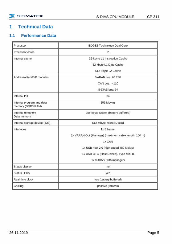
Processor EDGE2-Technology Dual Core
Processor cores 2
Internal cache 32-kbyte L1 Instruction Cache
32-kbyte L1 Data Cache
512-kbyte L2 Cache
Addressable I/O/P modules VARAN bus: 65.280
CAN bus: > 110
S-DIAS bus: 64
Internal I/O no
Internal program and data
memory (DDR3 RAM)
256 Mbytes
Internal remanent
Data memory
256-kbyte SRAM (battery buffered)
Internal storage device (IDE) 512-Mbyte microSD card
Interfaces 1x Ethernet
2x VARAN Out (Manager) (maximum cable length: 100 m)
1x CAN
1x USB host 2.0 (high speed 480 Mbit/s)
1x USB-OTG (Host/Device), Type Mini B
1x S-DIAS (with manager)
Status display no
Status LEDs yes
Real-time clock yes (battery buffered)
Cooling passive (fanless)
CP 311 S-DIAS CPU MODULE
Page 6 26.11.2019
1.2 Standard Configuration
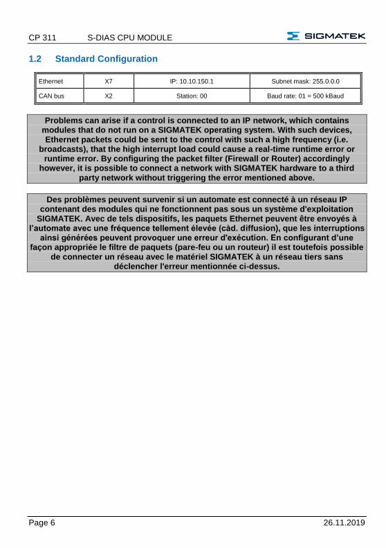
Ethernet X7 IP: 10.10.150.1 Subnet mask: 255.0.0.0
CAN bus X2 Station: 00 Baud rate: 01 = 500 kBaud
Problems can arise if a control is connected to an IP network, which contains modules that do not run on a SIGMATEK operating system. With such devices, Ethernet packets could be sent to the control with such a high frequency (i.e.
broadcasts), that the high interrupt load could cause a real-time runtime error or runtime error. By configuring the packet filter (Firewall or Router) accordingly
however, it is possible to connect a network with SIGMATEK hardware to a third party network without triggering the error mentioned above.
Des problèmes peuvent survenir si un automate est connecté à un réseau IP contenant des modules qui ne fonctionnent pas sous un système d'exploitation
SIGMATEK. Avec de tels dispositifs, les paquets Ethernet peuvent être envoyés à l’automate avec une fréquence tellement élevée (càd. diffusion), que les interruptions
ainsi générées peuvent provoquer une erreur d'exécution. En configurant d’une façon appropriée le filtre de paquets (pare-feu ou un routeur) il est toutefois possible
de connecter un réseau avec le matériel SIGMATEK à un réseau tiers sans déclencher l'erreur mentionnée ci-dessus.
S-DIAS CPU MODULE CP 311
26.11.2019 Page 7
1.3 Electrical Requirements
1.3.1 Module Supply (Input)
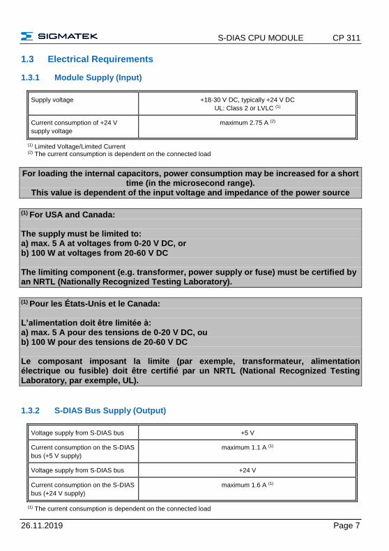
Supply voltage +18-30 V DC, typically +24 V DC
UL: Class 2 or LVLC (1)
Current consumption of +24 V
supply voltage
maximum 2.75 A (2)
(1) Limited Voltage/Limited Current (2) The current consumption is dependent on the connected load
For loading the internal capacitors, power consumption may be increased for a short time (in the microsecond range).
This value is dependent of the input voltage and impedance of the power source
(1) For USA and Canada: The supply must be limited to: a) max. 5 A at voltages from 0-20 V DC, or b) 100 W at voltages from 20-60 V DC The limiting component (e.g. transformer, power supply or fuse) must be certified by an NRTL (Nationally Recognized Testing Laboratory).
(1) Pour les États-Unis et le Canada: L’alimentation doit être limitée à: a) max. 5 A pour des tensions de 0-20 V DC, ou b) 100 W pour des tensions de 20-60 V DC Le composant imposant la limite (par exemple, transformateur, alimentation électrique ou fusible) doit être certifié par un NRTL (National Recognized Testing Laboratory, par exemple, UL).
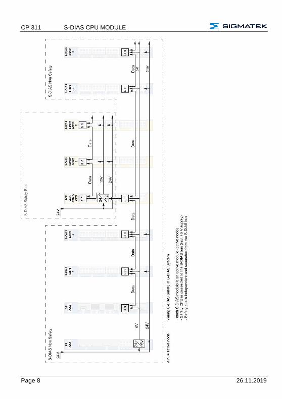
1.3.2 S-DIAS Bus Supply (Output)
Voltage supply from S-DIAS bus +5 V
Current consumption on the S-DIAS
bus (+5 V supply)
maximum 1.1 A (1)
Voltage supply from S-DIAS bus +24 V
Current consumption on the S-DIAS
bus (+24 V supply)
maximum 1.6 A (1)
(1) The current consumption is dependent on the connected load
CP 311 S-DIAS CPU MODULE
Page 8 26.11.2019
S-DIAS CPU MODULE CP 311
26.11.2019 Page 9
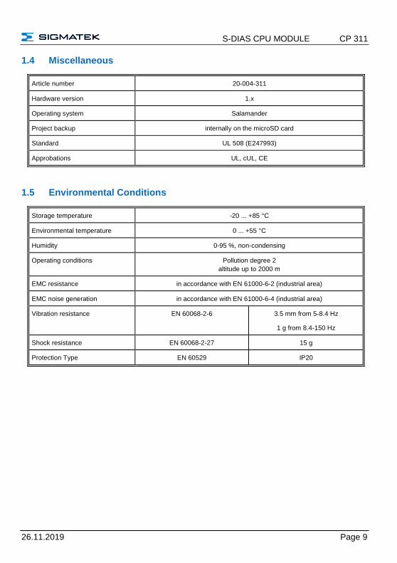
1.4 Miscellaneous
Article number 20-004-311
Hardware version 1.x
Operating system Salamander
Project backup internally on the microSD card
Standard UL 508 (E247993)
Approbations UL, cUL, CE
1.5 Environmental Conditions
Storage temperature -20 ... +85 °C
Environmental temperature 0 ... +55 °C
Humidity 0-95 %, non-condensing
Operating conditions Pollution degree 2
altitude up to 2000 m
EMC resistance in accordance with EN 61000-6-2 (industrial area)
EMC noise generation in accordance with EN 61000-6-4 (industrial area)
Vibration resistance EN 60068-2-6 3.5 mm from 5-8.4 Hz
1 g from 8.4-150 Hz
Shock resistance EN 60068-2-27 15 g
Protection Type EN 60529 IP20
CP 311 S-DIAS CPU MODULE
Page 10 26.11.2019
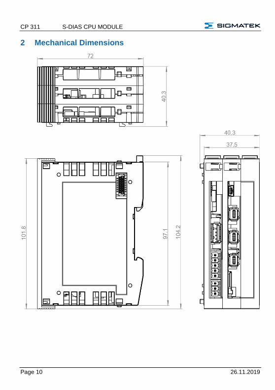
2 Mechanical Dimensions
S-DIAS CPU MODULE CP 311
26.11.2019 Page 11
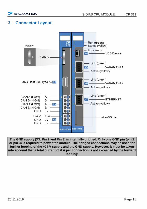
3 Connector Layout
The GND supply (X3: Pin 2 and Pin 3) is internally bridged. Only one GND pin (pin 2 or pin 3) is required to power the module. The bridged connections may be used for further looping of the +24 V supply and the GND supply. However, it must be taken
into account that a total current of 6 A per connection is not exceeded by the forward looping!
CP 311 S-DIAS CPU MODULE
Page 12 26.11.2019
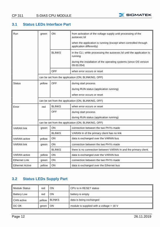
3.1 Status LEDs Interface Part
Run green ON from activation of the voltage supply until processing of the
autoexec.lsl
when the application is running (except when controlled through
application differently)
BLINKS in the CLI, while processing the autoexec.lsl until the application is
running
during the installation of the operating systems (since OS version
09.03.054)
OFF when error occurs or reset
can be set from the application (ON, BLINKING, OFF)
Status yellow OFF during start process
during RUN status (application running)
when error occurs or reset
can be set from the application (ON, BLINKING, OFF)
Error red BLINKS when error occurs or reset
OFF during start process
during RUN status (application running)
can be set from the application (ON, BLINKING, OFF)
VARAN link green ON connection between the two PHYs made
BLINKS VARAN In of the primary client has no link
VARAN active yellow ON data is exchanged over the VARAN bus
VARAN link green ON connection between the two PHYs made
BLINKS there is no connection between VARAN In and the primary client.
VARAN active yellow ON data is exchanged over the VARAN bus
Ethernet Link green ON connection between the two PHYs made
Ethernet Active yellow ON data is exchanged over the Ethernet bus
3.2 Status LEDs Supply Part
Module Status red ON CPU is in RESET status
Battery Low red ON battery is empty
CAN active yellow BLINKS data is being exchanged
DC OK green ON module is supplied with a voltage > 18 V
S-DIAS CPU MODULE CP 311
26.11.2019 Page 13
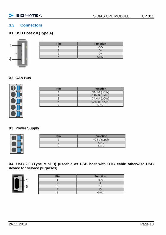
3.3 Connectors
X1: USB Host 2.0 (Type A)
X2: CAN Bus
X3: Power Supply
X4: USB 2.0 (Type Mini B) (useable as USB host with OTG cable otherwise USB device for service purposes)
Pin Function
1 +5 V 2 D- 3 D+ 4 GND
Pin Function
1 CAN A (LOW) 2 CAN B (HIGH) 3 CAN A (LOW) 4 CAN B (HIGH) 5 GND
Pin Function
1 +24 V supply 2 GND 3 GND
Pin Function
1 +5 V 2 D- 3 D+ 4 ID 5 GND
CP 311 S-DIAS CPU MODULE
Page 14 26.11.2019
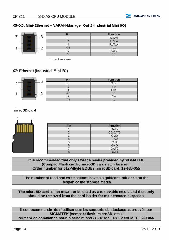
X5+X6: Mini-Ethernet – VARAN-Manager Out 2 (Industrial Mini I/O)
n.c. = do not use
X7: Ethernet (Industrial Mini I/O)
microSD card
It is recommended that only storage media provided by SIGMATEK (CompactFlash cards, microSD cards etc.) be used.
Order number for 512-Mbyte EDGE2 microSD card: 12-630-055
The number of read and write actions have a significant influence on the lifespan of the storage media.
The microSD card is not meant to be used as a removable media and thus only should be removed from the card holder for maintenance purposes.
Il est recommandé de n’utiliser que les supports de stockage approuvés par SIGMATEK (compact flash, microSD, etc.).
Numéro de commande pour la carte microSD 512 Mo EDGE2 est le: 12-630-055
Pin Function
1 Tx/Rx+ 2 Tx/Rx- 3 Rx/Tx+
4-5 n.c. 6 Rx/Tx-
7-8 n.c.
Pin Function
1 Tx+ 2 Tx- 3 Rx+
4-5 n.c. 6 Rx-
7-8 n.c.
Pin Function
1 DAT2 2 CD/DAT3 3 CMD 4 +3V3 5 CLK 6 GND 7 DAT0 8 DAT1
S-DIAS CPU MODULE CP 311
26.11.2019 Page 15
Le nombre de cycles de lecture et d'écriture a l’influence notable sur la durée de vie des supports de stockage.
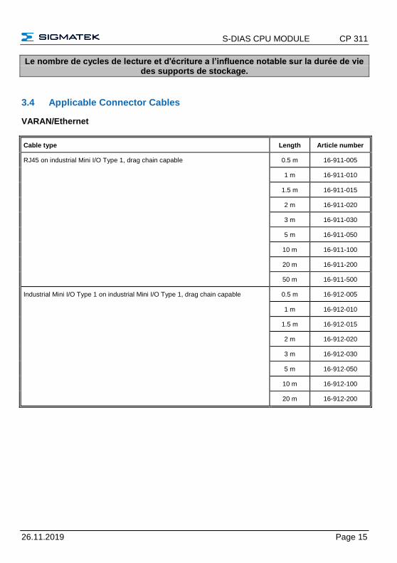
3.4 Applicable Connector Cables
VARAN/Ethernet
Cable type Length Article number
RJ45 on industrial Mini I/O Type 1, drag chain capable 0.5 m 16-911-005
1 m 16-911-010
1.5 m 16-911-015
2 m 16-911-020
3 m 16-911-030
5 m 16-911-050
10 m 16-911-100
20 m 16-911-200
50 m 16-911-500
Industrial Mini I/O Type 1 on industrial Mini I/O Type 1, drag chain capable 0.5 m 16-912-005
1 m 16-912-010
1.5 m 16-912-015
2 m 16-912-020
3 m 16-912-030
5 m 16-912-050
10 m 16-912-100
20 m 16-912-200
CP 311 S-DIAS CPU MODULE
Page 16 26.11.2019
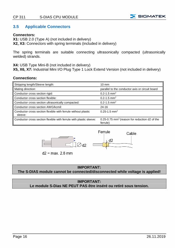
3.5 Applicable Connectors
Connectors: X1: USB 2.0 (Type A) (not included in delivery) X2, X3: Connectors with spring terminals (included in delivery) The spring terminals are suitable connecting ultrasonically compacted (ultrasonically welded) strands. X4: USB Type Mini-B (not included in delivery) X5, X6, X7: Industrial Mini I/O Plug Type 1 Lock Extend Version (not included in delivery) Connections:
Stripping length/Sleeve length: 10 mm
Mating direction: parallel to the conductor axis or circuit board
Conductor cross section rigid: 0.2-1.5 mm2
Conductor cross section flexible: 0.2-1.5 mm2
Conductor cross section ultrasonically compacted: 0.2-1.5 mm2
Conductor cross section AWG/kcmil: 24-16
Conductor cross section flexible with ferrule without plastic sleeve:
0.25-1.5 mm2
Conductor cross section flexible with ferrule with plastic sleeve: 0.25-0.75 mm2 (reason for reduction d2 of the ferrule)
IMPORTANT: The S-DIAS module cannot be connected/disconnected while voltage is applied!
IMPORTANT: Le module S-Dias NE PEUT PAS être inséré ou retiré sous tension.
S-DIAS CPU MODULE CP 311
26.11.2019 Page 17
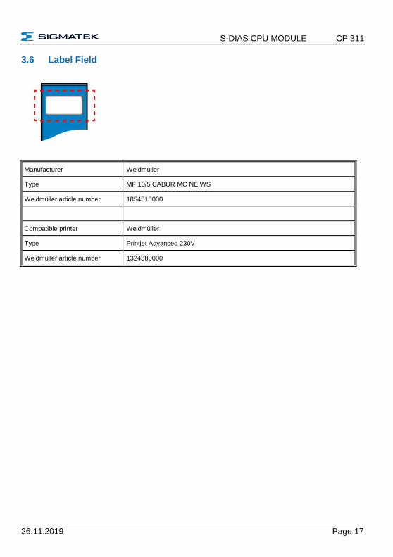
3.6 Label Field
Manufacturer Weidmüller
Type MF 10/5 CABUR MC NE WS
Weidmüller article number 1854510000
Compatible printer Weidmüller
Type Printjet Advanced 230V
Weidmüller article number 1324380000
CP 311 S-DIAS CPU MODULE
Page 18 26.11.2019
4 CAN Bus Setup
This section explains how to correctly configure the CAN bus. The following parameters must first be set: Station number and data transfer rate.
4.1 CAN Bus Station Number
Each CAN bus station is assigned its own station number. With this station number, data can be exchanged with other stations connected to the bus. In a CAN bus system however, each station number can only be assigned once!
4.2 Number of CAN Bus Participants
The maximum number of participants on the CAN bus depends on the cable length, termination resistance, data transfer rate and the drivers used in the participants.
With a termination resistance of 120 , at least 110 participants are possible.
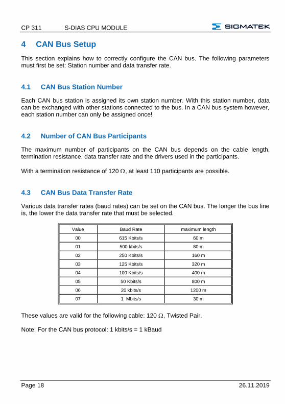
4.3 CAN Bus Data Transfer Rate
Various data transfer rates (baud rates) can be set on the CAN bus. The longer the bus line is, the lower the data transfer rate that must be selected.
Value Baud Rate maximum length
00 615 Kbits/s 60 m
01 500 kbits/s 80 m
02 250 Kbits/s 160 m
03 125 Kbits/s 320 m
04 100 Kbits/s 400 m
05 50 Kbits/s 800 m
06 20 kbits/s 1200 m
07 1 Mbits/s 30 m
These values are valid for the following cable: 120 , Twisted Pair. Note: For the CAN bus protocol: 1 kbits/s = 1 kBaud
S-DIAS CPU MODULE CP 311
26.11.2019 Page 19
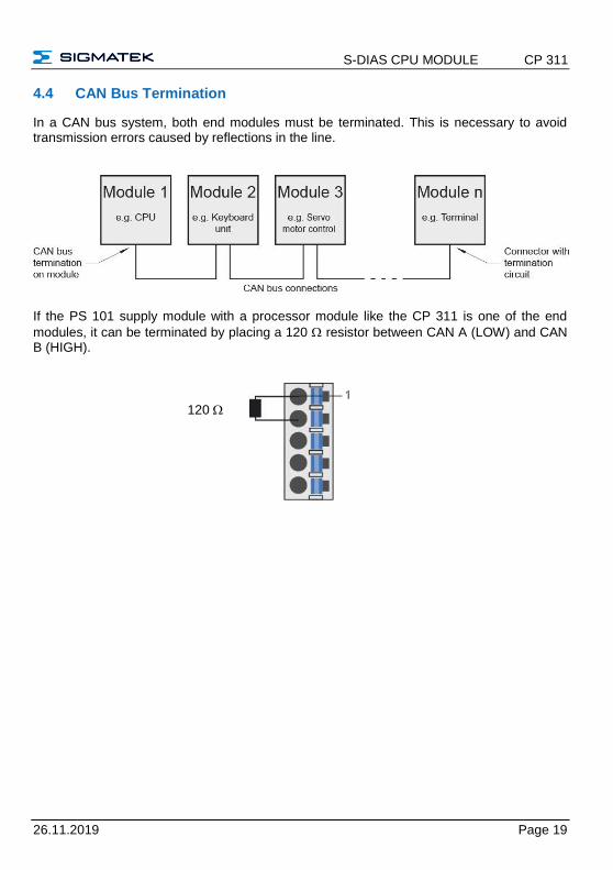
4.4 CAN Bus Termination
In a CAN bus system, both end modules must be terminated. This is necessary to avoid transmission errors caused by reflections in the line.
If the PS 101 supply module with a processor module like the CP 311 is one of the end
modules, it can be terminated by placing a 120 resistor between CAN A (LOW) and CAN B (HIGH).
120
CP 311 S-DIAS CPU MODULE
Page 20 26.11.2019
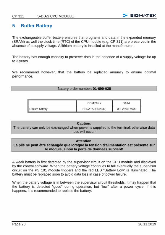
5 Buffer Battery
The exchangeable buffer battery ensures that programs and data in the expanded memory (SRAM) as well the clock time (RTC) of the CPU module (e.g. CP 311) are preserved in the absence of a supply voltage. A lithium battery is installed at the manufacturer.
The battery has enough capacity to preserve data in the absence of a supply voltage for up to 3 years.
We recommend however, that the battery be replaced annually to ensure optimal performance.
Battery order number: 01-690-028
COMPANY DATA
Lithium battery RENATA (CR2032) 3.0 V/235 mAh
Caution: The battery can only be exchanged when power is supplied to the terminal; otherwise data
loss will occur!
Attention: La pile ne peut être échangée que lorsque la tension d'alimentation est présente sur
le module, sinon la perte de données survient!
A weak battery is first detected by the supervisor circuit on the CPU module and displayed by the control software. When the battery voltage continues to fall eventually the supervisor circuit on the PS 101 module triggers and the red LED "Battery Low" is illuminated. The battery must be replaced soon to avoid data loss in case of power failure. When the battery voltage is in between the supervisor circuit thresholds, it may happen that the battery is detected "good" during operation, but "low" after a power cycle. If this happens, it is recommended to replace the battery.
S-DIAS CPU MODULE CP 311
26.11.2019 Page 21
6 Wiring Guidelines
The input filters, which suppress noise signals, allow operation in harsh environmental conditions. A careful wiring method is also recommended to ensure error-free function.
The following guidelines should be observed:
• Avoid parallel connections between input lines and load-bearing circuits.
• Protective circuits for all relays (RC networks or free-wheeling diodes)
• Correct wiring to ground
The ground bus should be connected to the control cabinet when possible!
Si possible la terre doit être connectée à l'armoire de commande!
IMPORTANT: The S-DIAS module cannot be connected/disconnected while voltage is applied!
IMPORTANT: Le module S-DIAS NE PEUT PAS être inséré ou retiré sous tension.
CP 311 S-DIAS CPU MODULE
Page 22 26.11.2019
7 Storage Media
It is recommended that only storage media provided by SIGMATEK (CompactFlash cards, microSD cards etc.) be used.
The number of read and write actions have a significant influence on the lifespan of the storage media.
Il est recommandé d’utiliser uniquement les supports de stockage fournis par SIGMATEK (Cartes CompactFlash, cartes microSD, etc). Le nombre de lectures et
d'écritures ont un effet significatif sur la durée de vie du support de stockage.
S-DIAS CPU MODULE CP 311
26.11.2019 Page 23
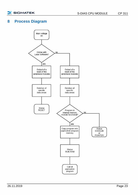
8 Process Diagram
CP 311 S-DIAS CPU MODULE
Page 24 26.11.2019
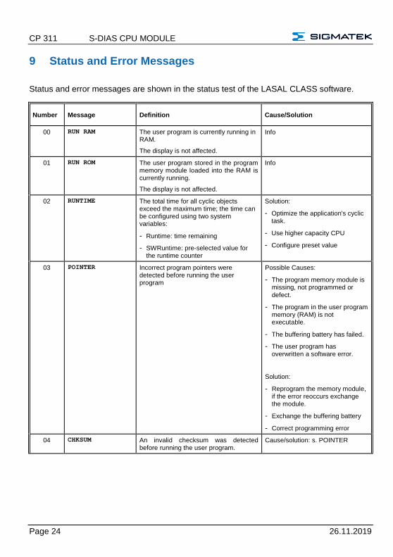
9 Status and Error Messages
Status and error messages are shown in the status test of the LASAL CLASS software.
Number Message Definition Cause/Solution
00 RUN RAM The user program is currently running in RAM.
The display is not affected.
Info
01 RUN ROM The user program stored in the program memory module loaded into the RAM is currently running.
The display is not affected.
Info
02 RUNTIME The total time for all cyclic objects exceed the maximum time; the time can be configured using two system variables:
- Runtime: time remaining
- SWRuntime: pre-selected value for the runtime counter
Solution:
- Optimize the application's cyclic task.
- Use higher capacity CPU
- Configure preset value
03 POINTER Incorrect program pointers were detected before running the user program
Possible Causes:
- The program memory module is missing, not programmed or defect.
- The program in the user program memory (RAM) is not executable.
- The buffering battery has failed.
- The user program has overwritten a software error.
Solution:
- Reprogram the memory module, if the error reoccurs exchange the module.
- Exchange the buffering battery
- Correct programming error
04 CHKSUM An invalid checksum was detected before running the user program.
Cause/solution: s. POINTER
S-DIAS CPU MODULE CP 311
26.11.2019 Page 25
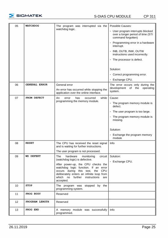
05 WATCHDOG The program was interrupted via the watchdog logic.
Possible Causes:
- User program interrupts blocked over a longer period of time (STI command forgotten)
- Programming error in a hardware interrupt.
- INB, OUTB, INW, OUTW instructions used incorrectly.
- The processor is defect.
Solution:
- Correct programming error.
- Exchange CPU.
06 GENERAL ERROR General error
An error has occurred while stopping the application over the online interface.
The error occurs only during the development of the operating system.
07 PROM DEFECT An error has occurred while programming the memory module.
Cause:
- The program memory module is defect.
- The user program is too large.
- The program memory module is missing.
Solution:
- Exchange the program memory module
08 RESET The CPU has received the reset signal and is waiting for further instructions.
The user program is not processed.
Info
09 WD DEFEKT The hardware monitoring circuit (watchdog logic) is defective.
After power-up, the CPU checks the watchdog logic function. If an error occurs during this test, the CPU deliberately enters an infinite loop from which no further instructions are accepted.
Solution:
- Exchange CPU.
10 STOP The program was stopped by the programming system.
11 PROG BUSY Reserved
12 PROGRAM LENGTH Reserved
13 PROG END A memory module was successfully programmed.
Info
CP 311 S-DIAS CPU MODULE
Page 26 26.11.2019
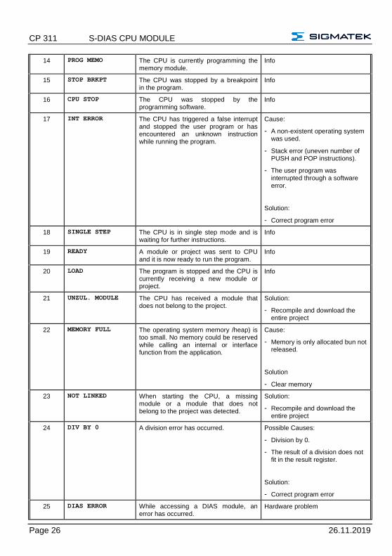
14 PROG MEMO The CPU is currently programming the memory module.
Info
15 STOP BRKPT The CPU was stopped by a breakpoint in the program.
Info
16 CPU STOP The CPU was stopped by the programming software.
Info
17 INT ERROR The CPU has triggered a false interrupt and stopped the user program or has encountered an unknown instruction while running the program.
Cause:
- A non-existent operating system was used.
- Stack error (uneven number of PUSH and POP instructions).
- The user program was interrupted through a software error.
Solution:
- Correct program error
18 SINGLE STEP The CPU is in single step mode and is waiting for further instructions.
Info
19 READY A module or project was sent to CPU and it is now ready to run the program.
Info
20 LOAD The program is stopped and the CPU is currently receiving a new module or project.
Info
21 UNZUL. MODULE The CPU has received a module that does not belong to the project.
Solution:
- Recompile and download the entire project
22 MEMORY FULL The operating system memory /heap) is too small. No memory could be reserved while calling an internal or interface function from the application.
Cause:
- Memory is only allocated bun not released.
Solution
- Clear memory
23 NOT LINKED When starting the CPU, a missing module or a module that does not belong to the project was detected.
Solution:
- Recompile and download the entire project
24 DIV BY 0 A division error has occurred. Possible Causes:
- Division by 0.
- The result of a division does not fit in the result register.
Solution:
- Correct program error
25 DIAS ERROR While accessing a DIAS module, an error has occurred.
Hardware problem
S-DIAS CPU MODULE CP 311
26.11.2019 Page 27
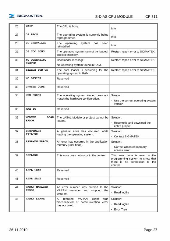
26 WAIT The CPU is busy. Info
27 OP PROG The operating system is currently being reprogrammed. Info
28 OP INSTALLED The operating system has been reinstalled. Info
29 OS TOO LONG The operating system cannot be loaded; too little memory.
Restart; report error to SIGMATEK.
30 NO OPERATING
SYSTEM Boot loader message.
No operating system found in RAM.
Restart; report error to SIGMATEK.
31 SEARCH FOR OS The boot loader is searching for the operating system in RAM.
Restart; report error to SIGMATEK.
32 NO DEVICE Reserved
33 UNUSED CODE Reserved
34 MEM ERROR The operating system loaded does not match the hardware configuration.
Solution:
- Use the correct operating system version
35 MAX IO Reserved
36 MODULE LOAD
ERROR The LASAL Module or project cannot be loaded.
Solution:
- Recompile and download the entire project
37 BOOTIMAGE
FAILURE A general error has occurred while loading the operating system.
Solution:
- Contact SIGMATEK
38 APPLMEM ERROR An error has occurred in the application memory (user heap).
Solution:
- Correct allocated memory access error
39 OFFLINE This error does not occur in the control. This error code is used in the programming system to show that there is no connection to the control.
40 APPL LOAD Reserved
41 APPL SAVE Reserved
44 VARAN MANAGER
ERROR An error number was entered In the VARAN manager and stopped the program.
Solution:
- Read logfile
45 VARAN ERROR A required VARAN client was disconnected or communication error has occurred.
Solution:
- Read logfile
- Error Tree
CP 311 S-DIAS CPU MODULE
Page 28 26.11.2019
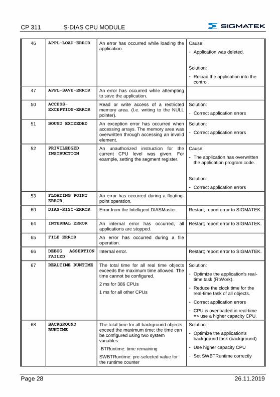
46 APPL-LOAD-ERROR An error has occurred while loading the application.
Cause:
- Application was deleted.
Solution:
- Reload the application into the control.
47 APPL-SAVE-ERROR An error has occurred while attempting to save the application.
50 ACCESS-
EXCEPTION-ERROR Read or write access of a restricted memory area. (I.e. writing to the NULL pointer).
Solution:
- Correct application errors
51 BOUND EXCEEDED An exception error has occurred when accessing arrays. The memory area was overwritten through accessing an invalid element.
Solution:
- Correct application errors
52 PRIVILEDGED
INSTRUCTION An unauthorized instruction for the current CPU level was given. For example, setting the segment register.
Cause:
- The application has overwritten the application program code.
Solution:
- Correct application errors
53 FLOATING POINT
ERROR An error has occurred during a floating-point operation.
60 DIAS-RISC-ERROR Error from the Intelligent DIASMaster. Restart; report error to SIGMATEK.
64 INTERNAL ERROR An internal error has occurred, all applications are stopped.
Restart; report error to SIGMATEK.
65 FILE ERROR An error has occurred during a file operation.
66 DEBUG ASSERTION
FAILED Internal error. Restart; report error to SIGMATEK.
67 REALTIME RUNTIME The total time for all real time objects exceeds the maximum time allowed. The time cannot be configured.
2 ms for 386 CPUs
1 ms for all other CPUs
Solution:
- Optimize the application's real-time task (RtWork).
- Reduce the clock time for the real-time task of all objects.
- Correct application errors
- CPU is overloaded in real-time => use a higher capacity CPU.
68 BACKGROUND
RUNTIME The total time for all background objects exceed the maximum time; the time can be configured using two system variables:
-BTRuntime: time remaining
SWBTRuntime: pre-selected value for the runtime counter
Solution:
- Optimize the application's background task (background)
- Use higher capacity CPU
- Set SWBTRuntime correctly
S-DIAS CPU MODULE CP 311
26.11.2019 Page 29
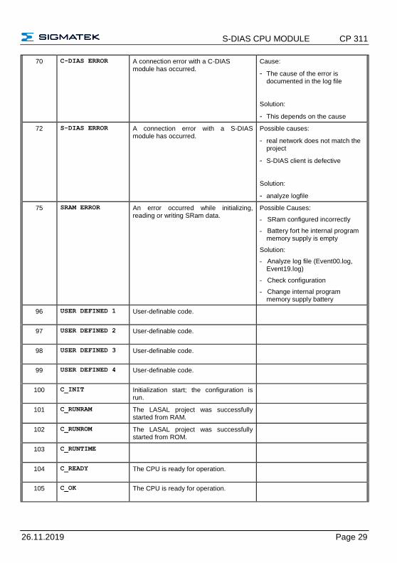
70 C-DIAS ERROR A connection error with a C-DIAS module has occurred.
Cause:
- The cause of the error is documented in the log file
Solution:
- This depends on the cause
72 S-DIAS ERROR A connection error with a S-DIAS module has occurred.
Possible causes:
- real network does not match the project
- S-DIAS client is defective
Solution:
- analyze logfile
75 SRAM ERROR An error occurred while initializing, reading or writing SRam data.
Possible Causes:
- SRam configured incorrectly
- Battery fort he internal program memory supply is empty
Solution:
- Analyze log file (Event00.log, Event19.log)
- Check configuration
- Change internal program memory supply battery
96 USER DEFINED 1 User-definable code.
97 USER DEFINED 2 User-definable code.
98 USER DEFINED 3 User-definable code.
99 USER DEFINED 4 User-definable code.
100 C_INIT Initialization start; the configuration is run.
101 C_RUNRAM The LASAL project was successfully started from RAM.
102 C_RUNROM The LASAL project was successfully started from ROM.
103 C_RUNTIME
104 C_READY The CPU is ready for operation.
105 C_OK The CPU is ready for operation.
CP 311 S-DIAS CPU MODULE
Page 30 26.11.2019
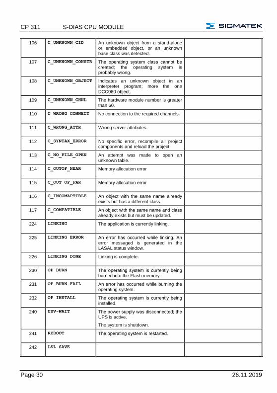
106 C_UNKNOWN_CID An unknown object from a stand-alone or embedded object, or an unknown base class was detected.
107 C_UNKNOWN_CONSTR The operating system class cannot be created; the operating system is probably wrong.
108 C_UNKNOWN_OBJECT Indicates an unknown object in an interpreter program; more the one DCC080 object.
109 C_UNKNOWN_CHNL The hardware module number is greater than 60.
110 C_WRONG_CONNECT No connection to the required channels.
111 C_WRONG_ATTR Wrong server attributes.
112 C_SYNTAX_ERROR No specific error, recompile all project components and reload the project.
113 C_NO_FILE_OPEN An attempt was made to open an unknown table.
114 C_OUTOF_NEAR Memory allocation error
115 C_OUT OF_FAR Memory allocation error
116 C_INCOMAPTIBLE An object with the same name already exists but has a different class.
117 C_COMPATIBLE An object with the same name and class already exists but must be updated.
224 LINKING The application is currently linking.
225 LINKING ERROR An error has occurred while linking. An error messaged is generated in the LASAL status window.
226 LINKING DONE Linking is complete.
230 OP BURN The operating system is currently being burned into the Flash memory.
231 OP BURN FAIL An error has occurred while burning the operating system.
232 OP INSTALL The operating system is currently being installed.
240 USV-WAIT The power supply was disconnected; the UPS is active.
The system is shutdown.
241 REBOOT The operating system is restarted.
242 LSL SAVE
S-DIAS CPU MODULE CP 311
26.11.2019 Page 31
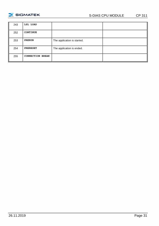
243 LSL LOAD
252 CONTINUE
253 PRERUN The application is started.
254 PRERESET The application is ended.
255 CONNECTION BREAK
CP 311 S-DIAS CPU MODULE
Page 32 26.11.2019
10 Application Exceptions
10.1 The File System Does Not Support Safe Writing via SRAM
If files are stored, modified or written on the microSD card from the user program, these files must always be stored with a fixed maximum size. Since changes in size and the simultaneous shutdown of the voltage supply can corrupt the file system, a later change in the file size is not allowed.
10.2 Data Breakpoint
This CPU does not support the data breakpoint feature.
S-DIAS CPU MODULE CP 311
26.11.2019 Page 33
11 Wiring Guidelines
The input filters, which suppress noise signals, allow operation in harsh environmental conditions. A careful wiring method is also recommended to ensure error-free function.
The following guidelines should be observed:
• Avoid parallel connections between input lines and load-bearing circuits.
• Protective circuits for all relays (RC networks or free-wheeling diodes)
• Correct wiring to ground
The ground bus should be connected to the control cabinet when possible!
IMPORTANT: The S-DIAS module cannot be connected/disconnected while voltage is applied!
CP 311 S-DIAS CPU MODULE
Page 34 26.11.2019
11.1 Shielding
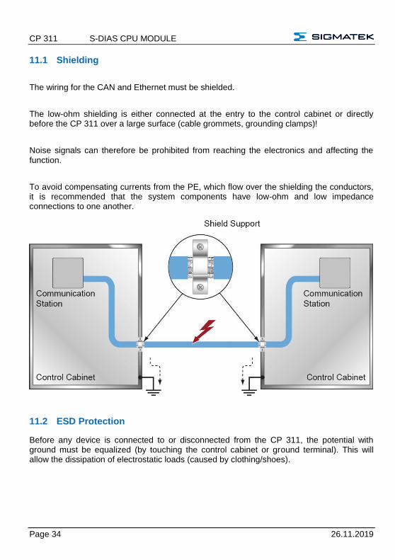
The wiring for the CAN and Ethernet must be shielded.
The low-ohm shielding is either connected at the entry to the control cabinet or directly before the CP 311 over a large surface (cable grommets, grounding clamps)!
Noise signals can therefore be prohibited from reaching the electronics and affecting the function.
To avoid compensating currents from the PE, which flow over the shielding the conductors, it is recommended that the system components have low-ohm and low impedance connections to one another.
11.2 ESD Protection
Before any device is connected to or disconnected from the CP 311, the potential with ground must be equalized (by touching the control cabinet or ground terminal). This will allow the dissipation of electrostatic loads (caused by clothing/shoes).
S-DIAS CPU MODULE CP 311
26.11.2019 Page 35
12 Strain Relief
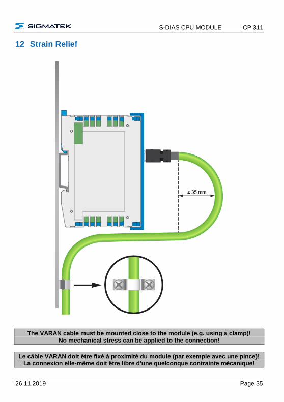
The VARAN cable must be mounted close to the module (e.g. using a clamp)! No mechanical stress can be applied to the connection!
Le câble VARAN doit être fixé à proximité du module (par exemple avec une pince)! La connexion elle-même doit être libre d'une quelconque contrainte mécanique!
CP 311 S-DIAS CPU MODULE
Page 36 26.11.2019
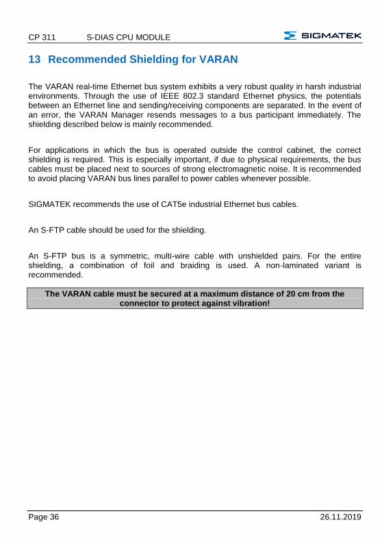
13 Recommended Shielding for VARAN
The VARAN real-time Ethernet bus system exhibits a very robust quality in harsh industrial environments. Through the use of IEEE 802.3 standard Ethernet physics, the potentials between an Ethernet line and sending/receiving components are separated. In the event of an error, the VARAN Manager resends messages to a bus participant immediately. The shielding described below is mainly recommended.
For applications in which the bus is operated outside the control cabinet, the correct shielding is required. This is especially important, if due to physical requirements, the bus cables must be placed next to sources of strong electromagnetic noise. It is recommended to avoid placing VARAN bus lines parallel to power cables whenever possible.
SIGMATEK recommends the use of CAT5e industrial Ethernet bus cables.
An S-FTP cable should be used for the shielding.
An S-FTP bus is a symmetric, multi-wire cable with unshielded pairs. For the entire shielding, a combination of foil and braiding is used. A non-laminated variant is recommended.
The VARAN cable must be secured at a maximum distance of 20 cm from the connector to protect against vibration!
S-DIAS CPU MODULE CP 311
26.11.2019 Page 37
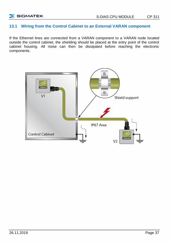
13.1 Wiring from the Control Cabinet to an External VARAN component
If the Ethernet lines are connected from a VARAN component to a VARAN node located outside the control cabinet, the shielding should be placed at the entry point of the control cabinet housing. All noise can then be dissipated before reaching the electronic components.
CP 311 S-DIAS CPU MODULE
Page 38 26.11.2019
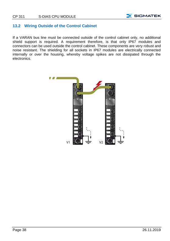
13.2 Wiring Outside of the Control Cabinet
If a VARAN bus line must be connected outside of the control cabinet only, no additional shield support is required. A requirement therefore, is that only IP67 modules and connectors can be used outside the control cabinet. These components are very robust and noise resistant. The shielding for all sockets in IP67 modules are electrically connected internally or over the housing, whereby voltage spikes are not dissipated through the electronics.
S-DIAS CPU MODULE CP 311
26.11.2019 Page 39
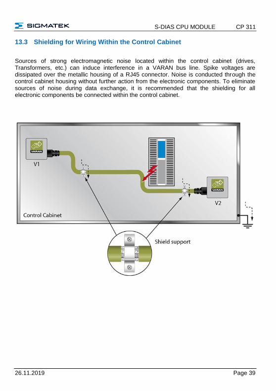
13.3 Shielding for Wiring Within the Control Cabinet
Sources of strong electromagnetic noise located within the control cabinet (drives, Transformers, etc.) can induce interference in a VARAN bus line. Spike voltages are dissipated over the metallic housing of a RJ45 connector. Noise is conducted through the control cabinet housing without further action from the electronic components. To eliminate sources of noise during data exchange, it is recommended that the shielding for all electronic components be connected within the control cabinet.
CP 311 S-DIAS CPU MODULE
Page 40 26.11.2019
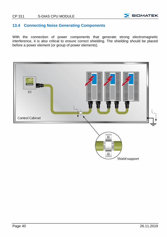
13.4 Connecting Noise Generating Components
With the connection of power components that generate strong electromagnetic interference, it is also critical to ensure correct shielding. The shielding should be placed before a power element (or group of power elements).
S-DIAS CPU MODULE CP 311
26.11.2019 Page 41
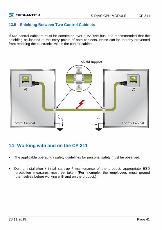
13.5 Shielding Between Two Control Cabinets
If two control cabinets must be connected over a VARAN bus, it is recommended that the shielding be located at the entry points of both cabinets. Noise can be thereby prevented from reaching the electronics within the control cabinet.
14 Working with and on the CP 311
• The applicable operating / safety guidelines for personal safety must be observed.
• During installation / initial start-up / maintenance of the product, appropriate ESD protection measures must be taken (For example: the employees must ground themselves before working with and on the product.)
CP 311 S-DIAS CPU MODULE
Page 42 26.11.2019
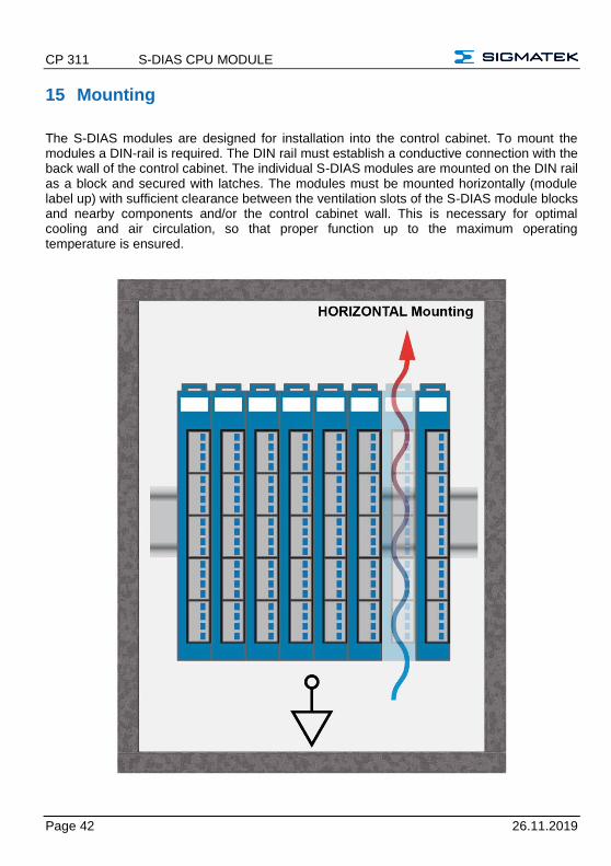
15 Mounting
The S-DIAS modules are designed for installation into the control cabinet. To mount the modules a DIN-rail is required. The DIN rail must establish a conductive connection with the back wall of the control cabinet. The individual S-DIAS modules are mounted on the DIN rail as a block and secured with latches. The modules must be mounted horizontally (module label up) with sufficient clearance between the ventilation slots of the S-DIAS module blocks and nearby components and/or the control cabinet wall. This is necessary for optimal cooling and air circulation, so that proper function up to the maximum operating temperature is ensured.
S-DIAS CPU MODULE CP 311
26.11.2019 Page 43
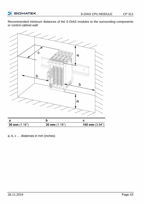
Recommended minimum distances of the S-DIAS modules to the surrounding components or control cabinet wall:
a, b, c … distances in mm (inches)
CP 311 S-DIAS CPU MODULE
Page 44 26.11.2019
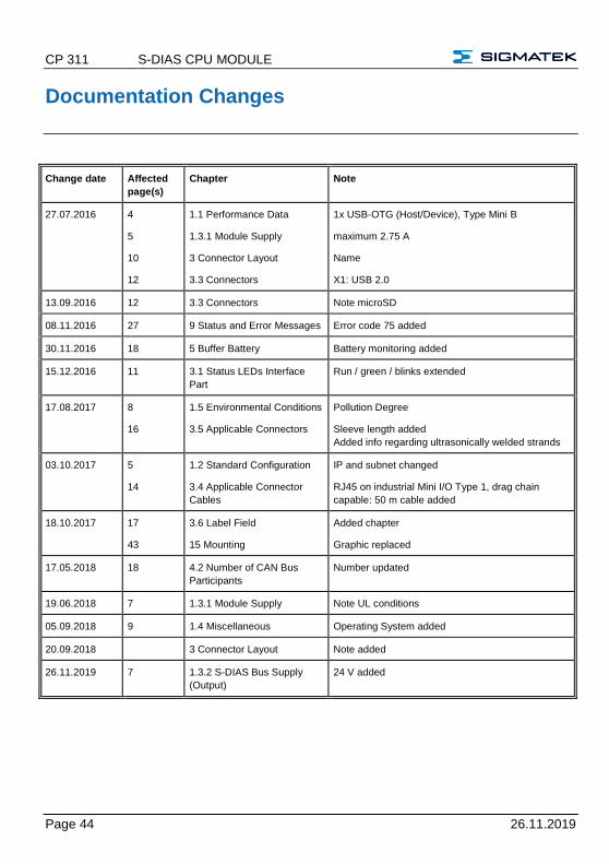
Documentation Changes
Change date Affected
page(s)
Chapter Note
27.07.2016 4
5
10
12
1.1 Performance Data
1.3.1 Module Supply
3 Connector Layout
3.3 Connectors
1x USB-OTG (Host/Device), Type Mini B
maximum 2.75 A
Name
X1: USB 2.0
13.09.2016 12 3.3 Connectors Note microSD
08.11.2016 27 9 Status and Error Messages Error code 75 added
30.11.2016 18 5 Buffer Battery Battery monitoring added
15.12.2016 11 3.1 Status LEDs Interface
Part
Run / green / blinks extended
17.08.2017 8
16
1.5 Environmental Conditions
3.5 Applicable Connectors
Pollution Degree
Sleeve length added
Added info regarding ultrasonically welded strands
03.10.2017 5
14
1.2 Standard Configuration
3.4 Applicable Connector
Cables
IP and subnet changed
RJ45 on industrial Mini I/O Type 1, drag chain
capable: 50 m cable added
18.10.2017 17
43
3.6 Label Field
15 Mounting
Added chapter
Graphic replaced
17.05.2018 18 4.2 Number of CAN Bus
Participants
Number updated
19.06.2018 7 1.3.1 Module Supply Note UL conditions
05.09.2018 9 1.4 Miscellaneous Operating System added
20.09.2018 3 Connector Layout Note added
26.11.2019 7 1.3.2 S-DIAS Bus Supply
(Output)
24 V added