Embed Size (px)
Citation preview

Preface, Contents
Technical Description1
Installation and Commissioning 2
Configuration with STEP 7 3
Data Exchange between the User Program and AS-i Slaves 4
Using the Command Interface5
Diagnostics and Interrupts of theCP 343−2
6
Dealing with Problems /Error Displays
7
Appendix
AS-Interface Protocol Implemen-tation Conformance Statement A
References and Literature B
Notes on the CE Mark C
Glossary D
Index
Release 08/2008C79000−G8976−C149−04
CP 343−2 / CP 343−2 PAS−Interface Master
Manual
SIMATIC NET
The following supplements (Edition 08/2010) belong to this documentation
1 Technical description 1.10 AS-Interface operation with 24 V voltage (AS-i Power24V)
5 Using the command interface 5.1 Description of FC "ASI_3422" (supplements 5.2 Description of the AS-i-slave commands (supplements)
7 Dealing with problems / error displays 7.1 Replacing a defective AS-i slave/automatic address programming 7.2 Error displays/remedying errors (incompatibilities)

2CP 343−2 / CP 343−2 P AS−Interface Master
Release 08/2008
C79000−G8976−C149−04
Classification of Safety-Related NoticesThis manual contains notices which you should observe to ensure your own perso-nal safety, as well as to protect the product and connected equipment. These noti-ces are highlighted in the manual by a warning triangle and are marked as followsaccording to the level of danger:
!Danger
indicates that death or severe personal injury will result if proper precautions arenot taken.
!Warning
indicates that death or severe personal injury can result if proper precautions arenot taken.
!Caution
with warning triangle indicates that minor personal injury can result if properprecautions are not taken.
Caution
without warning triangle indicates that damage to property can result if properprecautions are not taken.
Notice
indicates that an undesirable result or status can result if the relevant notice isignored.
Note
highlights important information on the product, using the product, or part of thedocumentation that is of particular importance and that will be of benefit to theuser.

3CP 343−2 / CP 343−2 P AS−Interface Master Release 08/2008
C79000−G8976−C149−04
Trademarks
SIMATIC�, SIMATIC HMI� and SIMATIC NET� are registered trademarks ofSIEMENS AG.
Third parties using for their own purposes any other names in this document whichrefer to trademarks might infringe upon the rights of the trademark owners.
Safety Instructions Regarding your Product:
Before you use the product described here, read the safety instructions below tho-roughly.
Qualified Personnel
Only qualified personnel should be allowed to install and work on this equipment.Qualified persons are defined as persons who are authorized to commission, toground, and to tag circuits, equipment, and systems in accordance with establis-hed safety practices and standards.
Correct Usage of Hardware Products
Note the following:
!Warning
This device and its components may only be used for the applications described inthe catalog or the technical description, and only in connection with devices orcomponents from other manufacturers which have been approved orrecommended by Siemens.
This product can only function correctly and safely if it is transported, stored, setup, and installed correctly, and operated and maintained as recommended.
Before you use the supplied sample programs or programs you have writtenyourself, make certain that no injury to persons nor damage to equipment canresult in your plant or process.
EU Directive: Do not start up until you have established that the machine on whichyou intend to run this component complies with the directive 98/37/EG.
Correct Usage of Software Products
Note the following:
!Warning
This software may only be used for the applications described in the catalog or thetechnical description, and only in connection with software products, devices, orcomponents from other manufacturers which have been approved orrecommended by Siemens.
Before you use the supplied sample programs or programs you have writtenyourself, make certain that no injury to persons nor damage to equipment canresult in your plant or process.

4CP 343−2 / CP 343−2 P AS−Interface Master
Release 08/2008
C79000−G8976−C149−04
Prior to Startup
Prior to startup, note the following:
Caution
Prior to startup, note the information and follow the instructions in the latest docu-mentation. You will find the ordering data for this documentation in the relevantcatalogs or contact your local Siemens office.
We have checked the contents of this manual for agreement with the hard-ware and software described. Since deviations cannot be precluded entirely,we cannot guarantee full agreement. However, the data in this manual arereviewed regularly and any necessary corrections included in subsequenteditions. Suggestions for improvement are welcomed.
Disclaimer of LiabilityCopyright � Siemens AG 2001−2008 All rights reserved
The reproduction, transmission or use of this document or its contents is notpermitted without express written authority . Offenders will be liable fordamages. All rights, including rights created by patent grant or registration ofa utility model or design, are reserved.
Siemens AGIndustry AutomationIndustrial CommunicationPostfach 4848, D-90327 Nuernberg Technical data subject to change.
Siemens Aktiengesellschaft G79000−G8976−C149−03

5CP 343−2 / CP 343−2 P AS−Interface Master Release 08/2008
C79000−G8976−C149−04
Preface
Purpose of the Manual
This manual supports you when using the following modules:
� CP 343-2
� CP 343-2 P
It contains information about how the PLC can address AS-i actuators and AS-isensors via this module.
What’s new?
The CP 343-2 (6GK7 343-2AH01-0XA0) and the CP 343-2 P(6GK7 343-2AH11-0XA0) as of firmware version V3.0 support all combinedtransaction type slaves (CTT slaves) according to AS-i Specification V3.
For these CPs as of firmware version V3.0, configuration of the CTT slaves issupported as of STEP 7 version 5.4 SP4. The command interface has beenexpanded to allow the transfer of CTT2 strings.
The following AS-i CPs do not support CTT slaves complying with AS-ispecification V3:
� 6GK7 343-2AH00-0XA0
� 6GK7 343-2AH10-0XA0
As of STEP 7 version 5.3 SP3, the selection of Siemens slaves is supported in theslave project engineering.
This issue of the manual also includes several corrections.
The notes on installation have been integrated in the manual. The productinformation bulletin no longer ships with the product.

Preface
6CP 343−2 / CP 343−2 P AS−Interface Master
Release 08/2008
C79000−G8976−C149−04
We recommend the following procedure when...
... You want an overall picture of the AS-Interface.
− First read ‘AS-Interface − Introduction and Basic Information’ (on theaccompanying product CD). This contains general information about theAS-Interface, abbreviated to AS-i in the following chapters.
... You want to set up an AS-i system and include the CP 343-2 module in it:
− You will find the relevant information about connecting and operating theCP 343-2 in Chapter 1, 2 and 3.
... You want to know how to operate the CP 343-2 from the PLC:
− Read Chapter 4.
− Chapter 5 explains the command interface.
Requirements
To understand this manual, you require the following:
� Basic knowledge of SIMATIC S7, STEP 7
� Familiarity with the manual ‘AS-Interface − Introduction and Basic Information’(on the accompanying product CD).
CD with sample program
The accompanying CD contains a sample program for operating the CP 343-2.
FAQs
You will find FAQs on Siemens AS-i products on the Internet on the Service andSupport pages of Industry Automation at the following address:
http://support.automation.siemens.com/WW/view/en/10805888
�

7CP 343−2 / CP 343−2 P AS−Interface Master Release 08/2008
C79000−G8976−C149−04
Contents
Preface 5. . . . . . . . . . . . . . . . . . . . . . . . . . . . . . . . . . . . . . . . . . . . . . . . . . . . . . . . . . . . . . . .
1 Technical Description 10. . . . . . . . . . . . . . . . . . . . . . . . . . . . . . . . . . . . . . . . . . . . . . . . . .
1.1 General Notes on Operation − Safety Warnings 11. . . . . . . . . . . . . . . . . .
1.2 Overview of the Module 12. . . . . . . . . . . . . . . . . . . . . . . . . . . . . . . . . . . . . . .
1.2.1 Uses of the Module 12. . . . . . . . . . . . . . . . . . . . . . . . . . . . . . . . . . . . . . . . . . .
1.2.2 The Product 14. . . . . . . . . . . . . . . . . . . . . . . . . . . . . . . . . . . . . . . . . . . . . . . . .
1.3 Technical Specifications of the Module 15. . . . . . . . . . . . . . . . . . . . . . . . . .
1.4 Approvals 16. . . . . . . . . . . . . . . . . . . . . . . . . . . . . . . . . . . . . . . . . . . . . . . . . . .
1.5 Displays and Operator Controls of the CP 343-2 17. . . . . . . . . . . . . . . . . .
1.6 Configuring using Buttons 22. . . . . . . . . . . . . . . . . . . . . . . . . . . . . . . . . . . . .
1.7 Modes 23. . . . . . . . . . . . . . . . . . . . . . . . . . . . . . . . . . . . . . . . . . . . . . . . . . . . . .
1.8 Permitted Slots for the CP 343-2 in the SIMATIC S7-300 and in the ET 200M 23. . . . . . . . . . . . . . . . . . . . . . . . . . . . . . . . . . . . . . . . . . . . . . . . .
1.9 Addressing the CP 343-2 in the S7 Automation System 24. . . . . . . . . . .
2 Installation and Commissioning 25. . . . . . . . . . . . . . . . . . . . . . . . . . . . . . . . . . . . . . . . .
2.1 Safety Warnings 25. . . . . . . . . . . . . . . . . . . . . . . . . . . . . . . . . . . . . . . . . . . . .
2.2 Installing and Commissioning the CP 26. . . . . . . . . . . . . . . . . . . . . . . . . . . .
3 Configuration with STEP 7 28. . . . . . . . . . . . . . . . . . . . . . . . . . . . . . . . . . . . . . . . . . . . . .
3.1 General Information on Configuring the CP 343-2 with STEP 7 28. . . . .
3.2 STEP 7 Basic Configuration 28. . . . . . . . . . . . . . . . . . . . . . . . . . . . . . . . . . .
3.3 Extra Configuration of the CP 3 43-2 P 30. . . . . . . . . . . . . . . . . . . . . . . . . .
3.3.1 Configuring in STEP 7 − Operating Parameters 30. . . . . . . . . . . . . . . . . .
3.3.2 Configuring AS-i Slaves 31. . . . . . . . . . . . . . . . . . . . . . . . . . . . . . . . . . . . . . .
3.4 Uploading the Actual Configuration to the PG (CP 3 43-2 P only) 38. . .
4 Data Exchange between User Program and AS−i Slaves 39. . . . . . . . . . . . . . . . . .
4.1 Exchanging AS−i Binary Values with Standard or A Slaves 39. . . . . . . . .
4.1.1 Addressing the Standard or A Slaves with the PLC 40. . . . . . . . . . . . . . .
4.1.2 Accessing Binary Data of Standard or A Slaves 42. . . . . . . . . . . . . . . . . .
4.2 Exchanging AS-i Binary Values with B Slaves 44. . . . . . . . . . . . . . . . . . . .
4.2.1 How the PLC Addresses the Slaves 45. . . . . . . . . . . . . . . . . . . . . . . . . . . .
4.2.2 Accessing Binary Data of B Slaves 46. . . . . . . . . . . . . . . . . . . . . . . . . . . . .
4.3 Points to Note about Binary Data of Analog Slaves 47. . . . . . . . . . . . . . .

Contents
8CP 343−2 / CP 343−2 P AS−Interface Master
Release 08/2008
C79000−G8976−C149−04
4.3.1 Point to Note About Analog Slaves 47. . . . . . . . . . . . . . . . . . . . . . . . . . . . .
4.3.2 Points to Note About AS-i Safety Slaves 47. . . . . . . . . . . . . . . . . . . . . . . . .
4.4 Transferring AS-i Analog Values 47. . . . . . . . . . . . . . . . . . . . . . . . . . . . . . . .
4.4.1 Addressing Analog Values of AS-i Slaves 48. . . . . . . . . . . . . . . . . . . . . . . .
4.4.2 Programming Examples 52. . . . . . . . . . . . . . . . . . . . . . . . . . . . . . . . . . . . . . .
5 Using the Command Interface 53. . . . . . . . . . . . . . . . . . . . . . . . . . . . . . . . . . . . . . . . . . .
5.1 Description of FC “ASI_3422” 53. . . . . . . . . . . . . . . . . . . . . . . . . . . . . . . . . .
5.2 Description of the AS-i Slave Commands 59. . . . . . . . . . . . . . . . . . . . . . . .
5.2.1 Set_Permanent_Parameter 62. . . . . . . . . . . . . . . . . . . . . . . . . . . . . . . . . . . .
5.2.2 Get_Permanent_Parameter 63. . . . . . . . . . . . . . . . . . . . . . . . . . . . . . . . . . . .
5.2.3 Write_Parameter 64. . . . . . . . . . . . . . . . . . . . . . . . . . . . . . . . . . . . . . . . . . . . .
5.2.4 Read_Parameter 65. . . . . . . . . . . . . . . . . . . . . . . . . . . . . . . . . . . . . . . . . . . . .
5.2.5 Store_Actual_Parameters 66. . . . . . . . . . . . . . . . . . . . . . . . . . . . . . . . . . . . .
5.2.6 Set_Extended_Permanent_Configuration 67. . . . . . . . . . . . . . . . . . . . . . . .
5.2.7 Get_Extended_Permanent_Configuration 68. . . . . . . . . . . . . . . . . . . . . . . .
5.2.8 Store_Actual_Configuration 69. . . . . . . . . . . . . . . . . . . . . . . . . . . . . . . . . . . .
5.2.9 Read_Extended_Actual_Configuration 70. . . . . . . . . . . . . . . . . . . . . . . . . .
5.2.10 Set_LPS 71. . . . . . . . . . . . . . . . . . . . . . . . . . . . . . . . . . . . . . . . . . . . . . . . . . . .
5.2.11 Set_Offline_Mode 72. . . . . . . . . . . . . . . . . . . . . . . . . . . . . . . . . . . . . . . . . . . .
5.2.12 Select Autoprogramming 73. . . . . . . . . . . . . . . . . . . . . . . . . . . . . . . . . . . . . .
5.2.13 Set_Operation_Mode 74. . . . . . . . . . . . . . . . . . . . . . . . . . . . . . . . . . . . . . . . .
5.2.14 Change_AS-I_Slave_Address 75. . . . . . . . . . . . . . . . . . . . . . . . . . . . . . . . . .
5.2.15 Get_AS-i_Slave_Status 76. . . . . . . . . . . . . . . . . . . . . . . . . . . . . . . . . . . . . . .
5.2.16 Get_LPS, Get_LAS, Get_LDS, Get_Flags 77. . . . . . . . . . . . . . . . . . . . . . .
5.2.17 Get_Extended_Total_Configuration 80. . . . . . . . . . . . . . . . . . . . . . . . . . . . .
5.2.18 Store_Extended_Total_Configuration 85. . . . . . . . . . . . . . . . . . . . . . . . . . . .
5.2.19 Write_Extended_Parameter_List 90. . . . . . . . . . . . . . . . . . . . . . . . . . . . . . .
5.2.20 Read_Extended_Parameter_Echo_List 91. . . . . . . . . . . . . . . . . . . . . . . . . .
5.2.21 Read_Write_CTT2_request 92. . . . . . . . . . . . . . . . . . . . . . . . . . . . . . . . . . . .
5.2.22 Read_Version_ID 93. . . . . . . . . . . . . . . . . . . . . . . . . . . . . . . . . . . . . . . . . . . .
5.2.23 Read_AS-i_Slave_ID 94. . . . . . . . . . . . . . . . . . . . . . . . . . . . . . . . . . . . . . . . .
5.2.24 Read_AS-i_Slave_Extended_ID1 95. . . . . . . . . . . . . . . . . . . . . . . . . . . . . . .
5.2.25 Write_AS-i_Slave_Extended_ID1 96. . . . . . . . . . . . . . . . . . . . . . . . . . . . . . .
5.2.26 Read_AS-i_Slave_Extended_ID2 97. . . . . . . . . . . . . . . . . . . . . . . . . . . . . . .
5.2.27 Read_AS-i_Slave_I/O 98. . . . . . . . . . . . . . . . . . . . . . . . . . . . . . . . . . . . . . . . .
5.2.28 Get_LPF 99. . . . . . . . . . . . . . . . . . . . . . . . . . . . . . . . . . . . . . . . . . . . . . . . . . . .
5.2.29 Write_AS-i_Slave_Parameter_String 100. . . . . . . . . . . . . . . . . . . . . . . . . . . .
5.2.30 Read_AS-i_Slave_Parameter_String 101. . . . . . . . . . . . . . . . . . . . . . . . . . . .
5.2.31 Read_AS-i_Slave_ID_String 102. . . . . . . . . . . . . . . . . . . . . . . . . . . . . . . . . . .
5.2.32 Read_AS-i_Slave_Diagnostic_String 103. . . . . . . . . . . . . . . . . . . . . . . . . . . .

Contents
9CP 343−2 / CP 343−2 P AS−Interface Master Release 08/2008
C79000−G8976−C149−04
6 Diagnostics and Interrrupts of the CP 343-2 104. . . . . . . . . . . . . . . . . . . . . . . . . . . . .
6.1 Overview 104. . . . . . . . . . . . . . . . . . . . . . . . . . . . . . . . . . . . . . . . . . . . . . . . . . . .
6.2 Interrupt Events 104. . . . . . . . . . . . . . . . . . . . . . . . . . . . . . . . . . . . . . . . . . . . . .
6.3 Sequence of Diagnostic Interrupt Processing 105. . . . . . . . . . . . . . . . . . . . .
6.4 Response to Interrupts in Different CP Operating States 106. . . . . . . . . . .
6.5 Local Data of the Diagnostic Organization Block (OB82) 106. . . . . . . . . . .
6.6 Reading the Diagnostic Data Record DS 1 108. . . . . . . . . . . . . . . . . . . . . . .
6.7 Programming Example 109. . . . . . . . . . . . . . . . . . . . . . . . . . . . . . . . . . . . . . . .
6.8 Diagnostic Interrupts: Some Examples 110. . . . . . . . . . . . . . . . . . . . . . . . . .
7 Dealing with Problems / Error Displays 11. . . . . . . . . . . . . . . . . . . . . . . . . . . . . . . . . .
7.1 Replacing a Defective AS-i Slave/Automatic Address Programming 111.
7.2 Error Displays/Remedying Errors 112. . . . . . . . . . . . . . . . . . . . . . . . . . . . . . .
A AS−Interface Protocol Implementation Conformance Statement (PICS) 11. . . . . . . . . . . . . . . . . . . . . . . . . . . . . . . . . . . . . . .
B References and Literature 1. . . . . . . . . . . . . . . . . . . . . . . . . . . . . . . . . . . . . . . . . . . . . .
C Notes on the CE Mark 1. . . . . . . . . . . . . . . . . . . . . . . . . . . . . . . . . . . . . . . . . . . . . . . . . .
D Glossary 12. . . . . . . . . . . . . . . . . . . . . . . . . . . . . . . . . . . . . . . . . . . . . . . . . . . . . . . . . . . . . .
Index 12. . . . . . . . . . . . . . . . . . . . . . . . . . . . . . . . . . . . . . . . . . . . . . . . . . . . . . . . . . . . . . . . . .

10CP 343−2 / CP 343−2 P AS−Interface Master
Release 08/2008
C79000−G8976−C149−04
1 Technical Description
This chapter describes the features of the module and familiarizes you with thebasic functions of the AS-i master module CP 343-2.
You will learn the following:
� The PLC systems on which the AS-Interface can be operated with theCP 343-2 / CP 343-2 P.
� Which displays and operator controls are available on the CP 343-2 /CP 343-2 P.
� Which modes are supported by the CP 343-2 / CP 343-2 P.
� Which options are available with the button configuration
� How addressing is handled on the CPU
Notice
The two device types CP 343-2 and CP 343-2 P are largely identical in terms offunctionality. The CP 343-2 P however has additional options for configuration andparameter assignment during startup (see Section 2.1).
The CP 343-2 P module is not therefore intended as a replacement for theCP 343-2 that can still be ordered!
Note
In the description below a distinction between the types CP 343-2 and CP 343-2 Pis made only where their performance characteristics differ.
Otherwise, unless specifically indicated, the name CP 343-2 (or CP) stands forboth device types CP 343-2 and CP 343-2 P

1 Technical Description
11CP 343−2 / CP 343−2 P AS−Interface Master Release 08/2008
C79000−G8976−C149−04
1.1 General Notes on Operation − Safety Warnings
Using the CP
You can use the CP 343-2 in the following automation systems:
� S7-300 − central configuration
� S7-300 − distributed configuration via ET 200M (IM153)
You can also connect the CP to an S7-400H via a redundant ET 200M.
Caution
To ensure protection from electrostatic discharge, the module may only beoperated when the front panel is closed.
When operating the module, implement the measures for preventing build up ofelectrostatic charges. For information on this topic, refer to the S7-300 devicemanual /4/.
You will find further information on conditions for use in Chapter 2.
!Warning
WARNING − EXPLOSION HAZARD: DO NOT DISCONNECT EQUIPMENTWHEN A FLAMMABLE OR COMBUSTIBLE ATMOSPHERE IS PRESENT.
!Warning
When used under hazardous conditions:
� If the cable or conduit entry point exceeds 70�C or the branching point ofconductors exceeds 80�C, special precautions must be taken: If the equipmentis operated in an air ambient of 50�C ... 60�C, only use cables with admittedmaximum operating temperature of at least 80�C.
� Provisions shall be made to prevent the rated voltage from being exceeded bytransient disturbances of more than 40%. This criterion is fulfilled, if suppliesare derived from SELV (Safety Extra Low Voltage) only.
Restrictions
Access to AS-i analog values using data records 140 to 147 and to the binaryvalues of the B slaves using data record 150 is not possible with the CPU 318 witha firmware version V1.1.3 or earlier.

1 Technical Description
12CP 343−2 / CP 343−2 P AS−Interface Master
Release 08/2008
C79000−G8976−C149−04
1.2 Overview of the Module
1.2.1 Uses of the Module
The CP 343-2 module can be operated in the automation systems (AS or PLC) ofthe S7-300 series and in the ET 200M system. It allows the connection of an AS-ichain to the programmable controllers listed above.
Using the CP 343-2, you can access the inputs and outputs on the AS-i slavesfrom the PLC. Depending on the slave type, you can access binary values oranalog values.
All AS-i slaves complying with AS-i specification V3.0 can be operated except forslaves complying with slave profile 7.1 and 7.2.
Binary actuators/sensors without
Branch of the AS-icable
AS-i power supply unit
Active module(with slave ASIC)Passive module
(without slave ASIC)
AS-i cable
Binary sensors/actuatorswith slave ASIC
CP 343-2S7−300
slave ASIC
Actuator/sensorwith direct connection
Figure 1-1 Using the CP 343-2 Master Module in the S7-300

1 Technical Description
13CP 343−2 / CP 343−2 P AS−Interface Master Release 08/2008
C79000−G8976−C149−04
Binary actuators/sensors without
Branch of the AS-icable
AS-i power supply unit
Active module(with slave ASIC)Passive module
(without slave ASIC)
AS-i cable
Binary sensors/actuatorswith slave ASIC
CP 343-2
slave ASIC
Actuator/sensorwith direct connection
ET 200M(IM 153) *)
PROFIBUS
Figure 1-2 Distributed Use of the Master Module CP 343-2 in the ET 200M
*) The CP 343-2 / CP 343-2 P is not released for operation in the IM 153-3.

1 Technical Description
14CP 343−2 / CP 343−2 P AS−Interface Master
Release 08/2008
C79000−G8976−C149−04
1.2.2 The Product
The product consists of the following:
1. One of the modules of the following type:
− CP 343-2 Order number 6GK7 343-2AH01-0XA0
− CP 343-2 P Order number 6GK7 343-2AH11-0XA0
2. Backplane bus connector
3. Labeling strips
4. CD with sample programs and documentation
The STEP 7 block FC “ASI_3422” (version 2.0) required for extended operationof the CP 343-2 is included on this CD.
Note
The 20-pin front connector for attaching to the AS-i cable is not supplied with theCP 343-2. You will find the order number of the front connector in the CatalogIK PI.

1 Technical Description
15CP 343−2 / CP 343−2 P AS−Interface Master Release 08/2008
C79000−G8976−C149−04
1.3 Technical Specifications of the Module
The CP 343-2 / CP 343-2 P module has the following characteristics:
Table 1-1 Technical Specifications
Feature Explanation/Values
Bus cycle time 5 ms with 31 slaves
10 ms for 62 slaves with the extendedaddressing mode
Depending on the slave profile, analog valueshave longer update times.
Configuration Using buttons on the front panel or withSTEP 7(download of the configuration withFC “ASI_3422”, see section 5.1)
Supported AS-i master profiles M4
Connection of the AS-i cable Via S7-300 front connector with screwcontacts (20-pin)
Current load between contact 17 and 19 andbetween 18 and 20 maximum 4 A
Address area 16 I bytes and 16 Q bytes in the analog areaof the S7-300
Current consumption from SIMATICbackplane bus
Power supply SIMATIC backplane bus
Current consumption from the AS-i cable
Power supply from the AS-i cable
max. 200 mA
5 V DC
max. 100 mA
DC 29.5 to 31.6 V, according to the AS–ispecification
Ambient conditions
� Operating temperature
� Transportation and storage temperature
� Relative humidity
� 0..60�C (horizontal installation of the S7standard rail)
� 0..40�C (vertical installation of the S7standard rail)
−40�C to +70�C
max. 95% at +25�C
Construction
� Module format
� Dimensions (W x H x D) in mm
� Weight
Compact module S7-300, single width
40 x 125 x 115
approx. 200 g

1 Technical Description
16CP 343−2 / CP 343−2 P AS−Interface Master
Release 08/2008
C79000−G8976−C149−04
1.4 Approvals
Table 1-2 Description of the Approvals
c-UL-us UL 508
CSA C22.2 No. 142
c-UL-us for hazardous locations ANSI / ISA 12.12.01, CSA C22.2 No. 213−M1987
CL. 1, Div. 2 GP.A.B.C.D T4
CL. 1, Zone 2, GP.IIC, T4
CL. 1, Zone 2, AEx nC IIC T4
FM FM 3611
CL. 1, Div. 2 GP.A.B.C.D T4
CL. 1, Zone 2, GP.IIC. T4
Ta: 0...+60°C
C-TICK AS/NZS 2064 (Class A)
CE EN 61000-6-2, EN 61000-6-4 (replacesEN 50081-2)
ATEX Zone 2 EN 60079-15:2005, EN 60079−0:2006
II 3 G Ex nA II T4
KEMA 08 ATEX 0003X
Note
The current approvals are printed on the module.

1 Technical Description
17CP 343−2 / CP 343−2 P AS−Interface Master Release 08/2008
C79000−G8976−C149−04
1.5 Displays and Operator Controls of the CP 343-2
The following diagram shows the front panel of the CP 343-2 with its indicators andoperator controls. The front connector for connecting the AS-i cable is below thecover on the front of the CP 343-2.
AS-i+ (brown)
AS-i− (blue)20
191817
SFRUN
APF
CERAUPCM
B20+
10+
SET
98
76
5
43
2
1
0
Contacts 17, 19 and 18, 20 are jumpered internally on the CP 343-2.
Figure 1-3 Front Connector Pin Assignment and Labeling on the CP 343-2
The CP 343-2 has internal contacts for two AS-i cables that are jumpered internallyon the CP. This allows the CP 343-2 to be “looped” into the AS-i cable.
Notice
The load capacity of the contacts is a maximum of 4 A. If this value is exceededon the AS-i cable, the CP 343-2 must not be “looped into” the AS-i cable but mustbe connected by a separate cable (only one pair of contacts used on theCP 343-2).
For further information on connecting the AS-i cable, refer to Section 2.2.

1 Technical Description
18CP 343−2 / CP 343−2 P AS−Interface Master
Release 08/2008
C79000−G8976−C149−04
Meaning of the Indicators and Operator Controls:
LED Meaning
SF System fault.
The LED is lit when:� The CP 343-2 is in the protected mode and an AS-i configuration error has
occurred (for example slave failed)� The CP detects an internal fault (for example EEPROM defective)� In response to a button command, the CP cannot execute the required mode
change at the present time (for example, because there is a slave withaddress 0).
RUN Indicates that the CP has started up correctly.
APF AS-i Power Fail.
This indicates that the voltage supplied to the AS-i cable by the AS-i powersupply unit is too low or there is a complete power outage.
CER Configuration Error.
This LED indicates whether the slave configuration detected on the AS-i cablematches the configuration configured on the CP (LPS). If they do not match, theCER LED is lit.
The CER LED is lit in the following situations:� When a configured AS-i slave does not exist on the AS-i cable
(for example failure of the slave).
� When a slave exists on the AS-i cable but it has not been configured
� When an attached slave has different configuration data (I/O configuration, ID code)from the slave configured on the CP.
� When the CP is in the offline phase.
AUP Autoprog available.
In the protected mode of the CP, this indicates that automatic addressprogramming of a slave is possible. Automatic address programming makes iteasier to replace a defective slave on the AS-i cable (for more detailedinformation, see Chapter 5.2.12).
CM Configuration Mode.
This LED indicates the mode.
Indicator on: configuration mode
Indicator on: protected mode

1 Technical Description
19CP 343−2 / CP 343−2 P AS−Interface Master Release 08/2008
C79000−G8976−C149−04
LED Meaning
� Configuration Mode
The configuration mode is used during AS-i installation and commissioning. In the configuration mode, the CP 343-2 can exchange data with every AS-islave connected to the AS-i cable (except for the AS-i slave with address ‘0’).Any AS-i slaves that are added later are detected immediately by the masterand activated and included in the cyclic data exchange. When installation and startup is completed, the CP 343-2 can be switched tothe protected mode using the SET button. Any AS-i slaves active at this pointare therefore configured. The following data of the AS-i slaves is stored in non-volatile memory on theCP 343-2:
− the PLC addresses
− the ID codes
− the I/O configuration
� Protected Mode
In the protected mode, the CP 343-2 exchanges data only with the configuredAS-i slaves. In this sense, “configured” means that the slave addresses andthe configuration data stored on the CP 343-2 match the values of existingAS-i slaves.
SET Button
The SET button is required for configuring the CP 343-2 in standard operation. Thebutton is only activated when the PLC is in the STOP mode.
If the CP 343-2 is in the configuration mode (CM LED lit), the CP 343-2 isconfigured automatically when the button is pressed. Configuration involves thefollowing steps:
1. The CP 343-2 saves the existing slave configuration as indicated by the LEDsof the active slaves as the expected configuration.
2. The CP 343-2 then changes to the protected mode.
If the CP 343-2 is in the protected mode (“CM” LED is not lit), pressing the buttonon the CP switches to the configuration mode.
For information on the method, refer to Section 1.6.
Display of the Detected and Activated AS-i Slaves
The detected and activated slaves are indicated by the LEDs 0 to 9 and the LEDs10+, 20+, B. The activated slaves are displayed in groups of ten. The switchover istime-controlled. The LEDs labeled 10+, 20+ indicate which group of 10 is currentlydisplayed by LEDs 0 to 9. If the “B” LED is lit, this indicates that the detected andactivated slaves are slaves from the extended address area B.

1 Technical Description
20CP 343−2 / CP 343−2 P AS−Interface Master
Release 08/2008
C79000−G8976−C149−04
Characteristics of the Slave Display
� If the CP 343-2 is in the configuration mode, all detected AS-i slaves aredisplayed.
� If the CP 343-2 is in the protected mode, all activated AS-i slaves areindicated by the LED being permanently lit. Failed or existing but unconfiguredAS-i slaves are indicated by the corresponding LED flashing.
B BExample 1
Indicates that the slaves withaddresses 1, 2 and 5 are detectedand activated.
Example 2
Indicates that the slaves withaddresses 20, 21 and 22 aredetected and activated.
Figure 1-4 Examples of the Display of Detected and Activated AS-i Slaves on the Front Panel of theCP 343-2

1 Technical Description
21CP 343−2 / CP 343−2 P AS−Interface Master Release 08/2008
C79000−G8976−C149−04
B BExample 3
Indicates that the slave withaddress 31B is detected andactivated.
Example 4
Indicates that the slaves withaddresses 10B and 17B aredetected and activated.
Figure 1-5 Examples of the Display of Detected and Activated AS-i Slaves on the Front Panel of theCP 343-2

1 Technical Description
22CP 343−2 / CP 343−2 P AS−Interface Master
Release 08/2008
C79000−G8976−C149−04
1.6 Configuring using Buttons
Preparation for Button Configuration
Make sure that the following situation applies:
� The PLC CPU must be switched to STOP.
� The CP 343-2 and all AS-i slaves must be connected to the AS-interface andsupplied with power.
� The AS-i slaves must have unique addresses other than “0”.
Setting the Configuration with Buttons
1. Check whether the CP 343-2 is in “configuration mode” (”CM” LED is lit).
If the ”CM” LED is not lit, change the CP 343-2 to the configuration mode withthe “SET” button.
2. Check whether all the slaves connected to the AS-interface exist and aredisplayed.
3. Press the SET button. This configures the CP 343-2; in other words, thedetected actual configuration is stored as the default in the non-volatileEEPROM. At the same time, the CP 343-2 is changed to the protected mode;the “CM” LED goes off. (See Section 1.5 > SET button)
The “CER” LED also goes off since following configuration, the “expectedconfiguration” stored on the CP 343-2 matches the “actual configuration” on theAS-Interface.
Note
Changing from the configuration mode to the protected mode is only possiblewhen there is no AS-i slave with address 0 connected to the AS-Interface. If aslave 0 is connected, the “SF” LED lights up when the SET button is pressed.
If you run a button configuration when there is no AS-i power supply (APF state) orwhen no AS-i slaves are connected, all the internal lists are set to their defaultvalues. In particular, all the AS-i parameters are set to = F Hex and theAutoAddress_Enable bit is set to = 1.
Notice
The following applies to the CP 3 43-2 P: A configuration of the AS-i slaves set bySTEP 7 and downloaded to the S7 station is transferred to the CP 3 43-2 P by theCPU during startup. Any configuration set with the buttons is then overwritten.

1 Technical Description
23CP 343−2 / CP 343−2 P AS−Interface Master Release 08/2008
C79000−G8976−C149−04
1.7 Modes
The CP recognizes two modes:
� Configuration mode
� Protected mode
Configuration mode
The configuration mode is used during AS-i installation and startup.
You can change the CP module from protected mode (productive operation) toconfiguration mode with the ”SET” button. (“CM” LED is lit, see Section 1.6).
In Configuration mode, the CP can exchange data with every AS-i slave connectedto the AS-i cable. Any AS-i slaves that are added later are detected immediately bythe master, activated and included in the cyclic data exchange.
Protected mode
In protected mode, the CP exchanges data only with the configured AS-i slaves.
After configuring with the “SET” button, activate protected mode by pressing the”SET” button again, the “CM” LED goes off.
1.8 Permitted Slots for the CP 343-2 in the SIMATIC S7-300and in the ET 200M
In principle, the CP can be installed in all the slots for I/O modules in the S7-300and ET 200M.
There may, however, be restrictions depending on the CPU or power supply unitbeing used in terms of the following:
� The expandability with several racks (multi-tier expansion of the PLC only withthe CPU 314 and higher),
� The electrical configuration, in other words the total current consumption fromthe S7 backplane bus.
For more detailed information, refer to the relevant SIMATIC system manuals /4/.

1 Technical Description
24CP 343−2 / CP 343−2 P AS−Interface Master
Release 08/2008
C79000−G8976−C149−04
1.9 Addressing the CP 343-2 in the S7 Automation System
The CP 343-2 can be addressed by the PLC like an analog module with 16 inputbytes and 16 output bytes. The CP occupies 16 input bytes and 16 output bytes inthe I/O address space of the S7 automation system (analog area on the AS).
Of the 16 bytes I/O address area of the CP 343-2, 31 x 4 bits are used for thebinary data of the AS-i standard slaves or A slaves. The remaining four bits arereserved for later applications.
The base address n of this address area is fixed as follows by the slot of theCP 343-2.
Rack 0
Module PS CPU IM CP CP CP CP CP CP CP CP
Slot number 1 2 3 4 5 6 7 8 9 10 11
Base address 1 2 3 256 272 288 304 320 336 352 368
Rack 1
Module IM CP CP CP CP CP CP CP CP
Slot number 3 4 5 6 7 8 9 10 11
Base address 384 400 416 432 448 464 480 496
Rack 2
Module IM CP CP CP CP CP CP CP CP
Slot number 3 4 5 6 7 8 9 10 11
Base address 512 528 544 560 576 592 608 624
Rack 3
Module IM CP CP CP CP CP CP CP CP
Slot number 3 4 5 6 7 8 9 10 11
Base address 640 656 672 688 704 720 736 752
Note
In most CPUs (for example, the CPU 315-2DP, 318), the slot-oriented addressingcan be modified with STEP 7 configuration (HW Config).
In particular, with the freely configurable CPUs, it is possible to address thestandard AS-i slaves or the A/B slaves with A addresses from the extendedaddress area via the process image of the inputs and outputs.

25CP 343−2 / CP 343−2 P AS−Interface Master Release 08/2008
C79000−G8976−C149−04
2 Installation and Commissioning
This chapter explains how to install and commission the module.
2.1 Safety Warnings
!Warning
When used under hazardous conditions (zone 2), the devices must be installed inan enclosure.
To comply with ATEX95 (EN 60079-15), this enclosure must meet therequirements of at least IP54 in compliance with EN 60529.
WARNING − EXPLOSION HAZARD: DO NOT DISCONNECT EQUIPMENTWHEN A FLAMMABLE OR COMBUSTIBLE ATMOSPHERE IS PRESENT.
!Warning� ”WARNING” − Explosion Hazard − Do not disconnect while circuit is live unless
area is known to be non-hazardous.
� ”WARNING” − Explosion Hazard − Substitution of components may impairsuitability for Class I, Division 2 or Zone 2.
� ”This equipment is suitable for use in Class I, Division 2, Groups A, B, C, D;Class I, Zone 2, Group IIC or non-hazardous locations.
!Warning
The device is designed for operation with safety extra-low voltage (SELV). Thismeans that only safety extra-low voltages (SELV) complying withIEC950/EN60950/ VDE0805 may be connected to the power supply terminals.
The power unit for supplying the device must comply with NEC Class 2 as descri-bed by the National Electrical Code(r) (ANSI/NFPA 70).
The power of all connected power units in total must correspond to a limited powersource (LPS).
If the cable to the external power unit is very long and liable to energy spikes, con-nect a surge protection element.
!Caution
Please keep to the ESD guidelines when installing and operating the CP.
Connect the CP only when the power supply is turned off.

2 Installation and Commissioning
26CP 343−2 / CP 343−2 P AS−Interface Master
Release 08/2008
C79000−G8976−C149−04
Ground/Chassis Ground Concept
Notice
To achieve the noise immunity of the CP 343-2 / CP 343-2 P the AS and AS-ipower supply unit must be correctly grounded.
Please note the instructions regarding the grounding and chassis ground conceptin the SIMATIC S7 installation guidelines; see “SIMATIC S7 Automation SystemS7-300 − Installation: installation manual” /4/.
2.2 Installing and Commissioning the CP
Installation
The CP can be installed in a SIMATIC S7-300 or an ET 200M.
Notice
The CP 343-2 / CP 343-2 P is not released for operation in the IM 153-3.
Step Explanation / Meaning
Note
Only wire up the S7-300 with the power switched off!
Follow the steps as described in detail in /4/ when wiring between the power supply and the CPU.
1. Install the CP on the S7 standard rail. Slots 4 to 11 are permitted for the CP in racks 0 to 3(connected by IM 360/361).
Proceed as in the sections dealing with setup andwiring, described in detail in /1/.
2. Establish the connection via the enclosed busconnector to the backplane bus.
3. Then secure the CP by the screws in its casing.
4. Connect the AS-i cable to the terminals on thefront connector of the CP.
Contact is made at terminal pairs 17 and 19 or 18and 20 of the front connector. Terminals 17 and 19and terminals 18 and 20 are electrically connectedwithin the CP.
The assignment of the terminal pair and the polarityare indicated on the front panel of the CP.
The second terminal pair (18/20) is intended forconnecting the AS-i power supply unit or a branchof the AS-i cable. This allows the CP to be “looped”into the AS-i cable. The AS-i power supply unit can,however, be connected to any point on the AS-icable.

2 Installation and Commissioning
27CP 343−2 / CP 343−2 P AS−Interface Master Release 08/2008
C79000−G8976−C149−04
!Caution
The load capacity of the AS-i contacts is a maximum of 4 A. If this value isexceeded on the AS-i cable, the CP must not be “looped into” the AS-i cable butmust be connected by a separate cable( only one pair of CP terminals used).
Step Explanation / Meaning
5. Turn on the power supply for the SIMATICstation and the AS-i system.
6. The remaining steps in commissioning involvedownloading the configuration data.
For details on configuration, refer to Section 1.6and 3.
�

28CP 343−2 / CP 343−2 P AS−Interface Master
Release 08/2008
C79000−G8976−C149−04
3 Configuration with STEP 7
This chapter explains how to configure the CP with STEP 7 as of V5.2.
You will learn the following:
� What basic configuration will need to create for the CP 343–2 and CP 343–2 P
� What other configuration options the CP 343–2 P provides
3.1 General Information on Configuring the CP 343-2 withSTEP 7
Significance of the Configuration in STEP 7
Configuration in STEP 7 is necessary for the use of the CP 343-2 in an S7-300.Here, a distinction must be made between the obligatory basic configuration andthe optional slave configuration for the CP 343–2 P.
The following applies to the CP 343–2 P:While configuration with the buttons as described in Section 1.6 simply allowsquerying of the current actual configuration, by configuring in STEP 7, you cancreate a defined configuration regardless of the actual configuration and downloadit to the CP.
Note
The information on the basic configuration in Section 3.2 applies both to theCP 343-2 and to the CP 343-2 P.
The information in Section 3.3 relates only to the CP 343-2 P!
3.2 STEP 7 Basic Configuration
Entering the AS-i Master into the S7-300 Station in HW Config
The CP 343-2 / CP 3 43-2 P is taken from the hardware catalog in STEP 7HW Config just like any other module and placed in the required slot in the rack ofthe S7-300 station.
After you have inserted the CP 343-2 / CP 3 43-2 P, there are still no AS-i slavesconfigured. In this default setting, the rules of “button configuration” apply initially(see Section 1.6).

3 Configuration with STEP 7
29CP 343−2 / CP 343−2 P AS−Interface Master Release 08/2008
C79000−G8976−C149−04
Configuring Properties of the CP 343-2 / CP 343-2 P
To view general information, addresses, and operating parameters and to configureor modify them, change to the Properties dialog of the CP 343-2 / CP 343-2 P.
� “General” Tab
Here, you can change the name of the CP.
� “Addresses” Tab
Reserved length:
� In the default setting, 16 bytesare reserved;
Start addresses:must be identical for inputs andoutputs.

3 Configuration with STEP 7
30CP 343−2 / CP 343−2 P AS−Interface Master
Release 08/2008
C79000−G8976−C149−04
3.3 Extra Configuration of the CP 3 43-2 P
Note
The information in Section 3.3 relates only to the CP 343-2 P!
3.3.1 Configuring in STEP 7 − Operating Parameters
� ”Operating Parameters” tab
The diagnostic interrupt can be se-lected here for the protected mode.
Automatic address programming ifa slave is replaced: If an AS-i slave is replaced (due toa fault), the address is programmedautomatically with the factory set-ting address ”0” for a replacementslave of the same type.
If this reaction is not desired, for ex-ample for safety reasons, the op-tion can be deselected here.
The settings you have made up to now in the Properties dialog are adequate to beable to access the AS-i slaves from the user program. If you want to set a moredetailed AS-i configuration with STEP 7, follow the steps below.

3 Configuration with STEP 7
31CP 343−2 / CP 343−2 P AS−Interface Master Release 08/2008
C79000−G8976−C149−04
3.3.2 Configuring AS-i Slaves
Notice
A configuration of the AS-i slaves set by STEP 7 and downloaded to the S7 stationis transferred from the CPU to the CP 343-2 P when the S7 station starts up. Anyconfiguration set with the buttons is then overwritten.
To configure a specific slave configuration, select the “Slave Configuration” tab.
Double-click on the row in the displayed table in which you want to enter an AS-islave with the corresponding address; this opens the Properties dialog for AS-islaves.
Take the AS-i slaves from the drop-down list. Three basic types of AS-i slave areavailable:
� AS-i A/B Slave Universal
AS-i slave with extended addressing mode
� AS-i Standard Slave Universal or AS-i Analog Slave
AS-i slave for the standard address area; if you use this slave type, you cannotplace an AS-i A/B slave at the same address in the B address area.
3 Configuration with STEP 7
32CP 343−2 / CP 343−2 P AS−Interface Master
Release 08/2008
C79000−G8976−C149−04
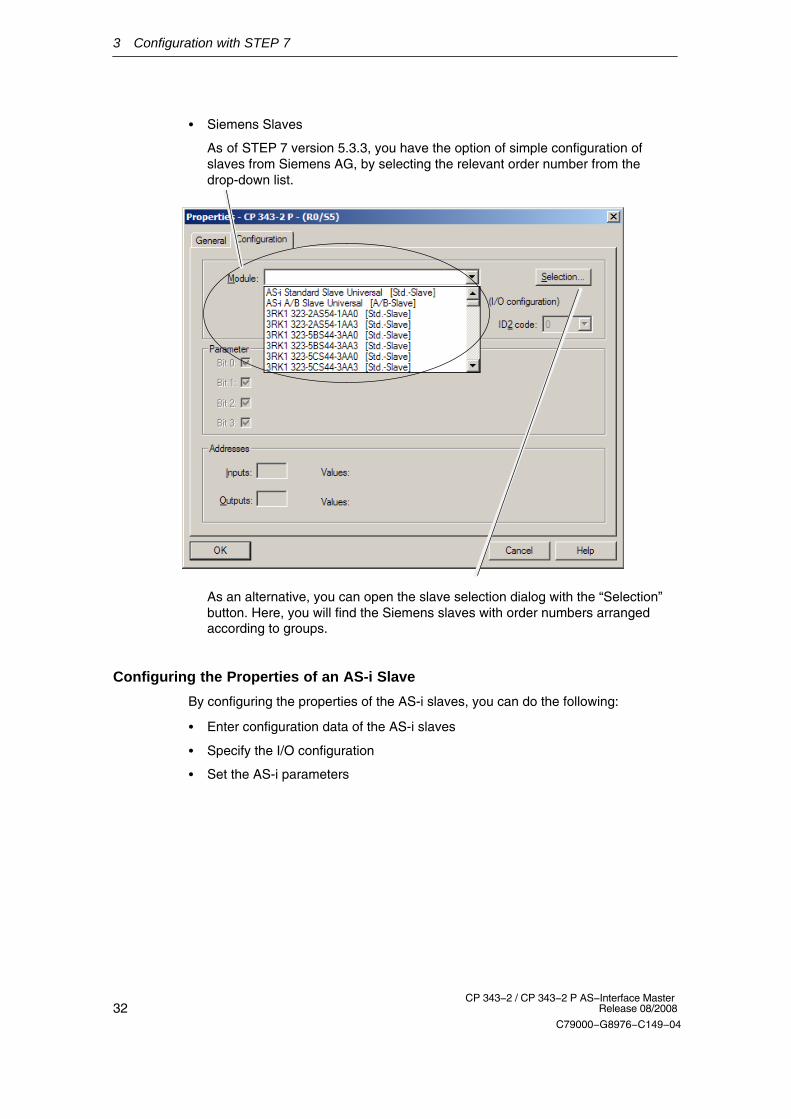
� Siemens Slaves
As of STEP 7 version 5.3.3, you have the option of simple configuration ofslaves from Siemens AG, by selecting the relevant order number from thedrop-down list.
As an alternative, you can open the slave selection dialog with the “Selection”button. Here, you will find the Siemens slaves with order numbers arrangedaccording to groups.
Configuring the Properties of an AS-i Slave
By configuring the properties of the AS-i slaves, you can do the following:
� Enter configuration data of the AS-i slaves
� Specify the I/O configuration
� Set the AS-i parameters

3 Configuration with STEP 7
33CP 343−2 / CP 343−2 P AS−Interface Master Release 08/2008
C79000−G8976−C149−04
Standard AS-i Slave
The AS-i standard slave can only be placed at an AS-i address in the A area. Thisaddress is then no longer available in the B area.
1) For AS−i slaves that do not support the ID1/ID2codes, the values F (hexadecimal) must beentered.
As an option, start-upparameters can be permittedhere;
Whether this parameter canbe used depends on theslave type.
Enter the following vendor information forthe AS-i slaves in this area:
� I/O configuration: standardizedmeaning;
� ID code: standardized meaning;
� ID1/2 code: Extended ID code as ofAS-i Specification 2.11).

3 Configuration with STEP 7
34CP 343−2 / CP 343−2 P AS−Interface Master
Release 08/2008
C79000−G8976−C149−04
Configuring Analog Slaves as Standard Slaves
If you want to configure an analog slave with more than two channels, use the AS-istandard slave.
You then set the properties of the analog interface using the combination of the I/Oconfiguration and the three ID codes. Please refer to the operating instructions ofthe AS-i slave you are using for information on the parameter settings.
These parameters are set in accordance with the DP standard V1.
Example:
General I/O configuration for analogslaves.
1) For AS-i slaves that do not support the ID1/ID2codes, the values FH must be entered.
ID codes for analog slaves as listedin the relevant operating instructions.
Here, for example:
� ID code: 3h
� ID1: Fh (is not evaluated)1)
� ID2: 5h = 2-channel analog slave

3 Configuration with STEP 7
35CP 343−2 / CP 343−2 P AS−Interface Master Release 08/2008
C79000−G8976−C149−04
AS-i A/B Slave
The AS-i A/B slave can either be placed at an AS-i address in the A or B area. TheB area can be used only when no AS-i standard slave is placed in the A area.
As an option, start-up para-meters can be permitted he-re;
Whether this parameter canbe used depends on the sla-ve type.
Only 3 bits are available forA/B slaves!
The 4th bit is required for theaddress switchover.
The parameters in this area specifythe slave profile.
As well as the I/O configuration:
� ID code: standardized meaning;
� ID1/2 code: Expanded ID codeas of AS-i Specification 2.1.
AS−i analog slaves with expanded address area
If you use an analog slave with only 2 channels, you can configure this as an AS-iA/B slave in the expanded address area. Configuration is as described above inthe section “AS-i A/B slave”.

3 Configuration with STEP 7
36CP 343−2 / CP 343−2 P AS−Interface Master
Release 08/2008
C79000−G8976−C149−04
Slaves Complying with AS-i Specification V3
AS-i slaves complying with AS-i Specification V3 (combined transaction type (CTT)2−5) are supported by the CP as of firmware version V3.0. You can access theanalog values of these slaves using data records 140 to 147.
Notice
In the corresponding digital values, STEP 7 does not indicate the correct numberof bits. Access to the user data by the user program is nevertheless always possi-ble.
The following screenshot shows an example of the “Slave Configuration” tab in theProperties dialog of a module with configured CTT slaves:
“Slave Configuration” tab in the Properties dialog of a CP 343–2 P (example): Notall bits of the I/O addresses of the CTT slaves are relevant!

3 Configuration with STEP 7
37CP 343−2 / CP 343−2 P AS−Interface Master Release 08/2008
C79000−G8976−C149−04
Table 3-1 shows the relevant bits of the CTT slaves.
Table 3-1
Slave in theexample(see figure)
Type, IO.ID.ID2 Relevant bits Non-relevant bits
Slave 1A CTT2, S−7.5.5 I0.0...I0.1
Q0.2...Q0.3
I0.2...I0.3
Q0.0...Q0.1
Slave 2A CTT2, S−7.A.5 I1.4...I1.5
Q1.6
I1.6...I1.7
Q1.4...Q1.5
Slave 3A CTT2, S−B.A.5 − All bits irrelevant. Data access usingdata record 140...147
Slave 4A CTT3, S−7.A.7 I2.4...I2.7
Q2.4...Q2.7 *)−
−
Slave 5A CTT3, S−7.A.A − All bits irrelevant. Data access usingdata record 140...147
Slave 6A CTT4, S−7.A.8
Q3.6
I3.4...I3.7
Q3.4, Q3.5
Slave 7A CTT4, S−7.A.9 − All bits irrelevant. Data access usingdata record 140...147
Slave 8A, 9A,10A, 11A
CTT5, S−6.0.x − All bits irrelevant. Data access usingdata record 140...147
*) Bit Q2.7 is not shown but can be used.
Note
Slaves with IO code 6 and ID code 0 occupy several AS-i addresses. The IO andID code specified by the vendor must be configured for each occupied AS-i ad-dress.

3 Configuration with STEP 7
38CP 343−2 / CP 343−2 P AS−Interface Master
Release 08/2008
C79000−G8976−C149−04
3.4 Uploading the Actual Configuration to the PG(CP 3 43-2 P only)
Aims
You can upload the current actual configuration over the CP 343–2 P to the openSTEP 7 project.
This allows you to
� read in a complex configuration and use it as a basis for a further configurationin STEP 7
� check a current configuration.
Note
The uploaded configuration is always the current actual configuration. This candeviate from the configuration set with the buttons and stored on the AS-i master ,for example when an AS-i slave is added or removed using the buttonconfiguration function.
When you download the configuration defined in the STEP 7 project to theCP 343-2, the configuration detected by the button configuration function isoverwritten.
Follow the steps below
Preparation: Create the basic configuration and download to the station:
1. Create a basic configuration by inserting the CP 343-2 P in an S7-300 stationwithout AS-i slaves in HW Config.
2. Download this basic configuration to the S7-300 station using HW Config.
Uploading:
3. Select the “AS-i Slave Options” tab in the Properties dialog of the CP.
4. Click the “Download to PG” button and, if a warning is displayed, simply confirmit.
An existing configuration in the STEP 7 project is overwritten. Before the newconfiguration is adopted, you must first confirm the warning.
5. Change to the “Slave Configuration” tab to view the actual configuration andedit it if necessary.
Tip:
To use the function for information despite an existing configuration in STEP 7, youcan upload the actual configuration and then after checking it, quit the dialog withthe “Cancel” button.�

39CP 343−2 / CP 343−2 P AS−Interface Master Release 08/2008
C79000−G8976−C149−04
4 Data Exchange between User Program andAS−i Slaves
This chapter provides you with the information you require to access the data ofthe AS-i slaves from the PLC user program via the CP 343-2. The chapter explainsthe transfer of the following:
� Binary values of the standard or A slaves via the PLC I/Os
� Binary values of the B slaves by reading or writing data record 150
� Analog values of the AS-i analog slaves complying with profile 7.3/7.4 byreading or writing data records 140−147
For information on using the data record numbers with the CPU 318, refer to“Restrictions” in Section 1.1.
4.1 Exchanging AS−i Binary Values with Standard or ASlaves
Interface between PLC CPU and CP 343-2
You can access the binary values of AS-i standard slaves or A slaves in the userprogram using suitable STEP 7 I/O commands.
PLC CPU
AS-islave 2
AS-islave 1
AS-islave31
ÍÍÍÍÍÍÍÍÍÍÍÍ
ÎÎÎÎÎÎÎÎÎÎÎÎ
Standard / Aslaves
ÍÍÍÍÍÍÎÎÎÎÎÎÍÍÍÍÍÍÎÎÎ
ÍÍÍÎÎÎÎÎÎ
Backplane bus AS-Interface
CP 343-2
I/O commands
(e.g. L PIW 288)
I/O commands
(e.g. T PQD 260) .
.
.
Figure 4-1

4 Data Exchange between User Program and AS−i Slaves
40CP 343−2 / CP 343−2 P AS−Interface Master
Release 08/2008
C79000−G8976−C149−04
4.1.1 Addressing the Standard or A Slaves with the PLC
Each standard or A slave on the AS-i cable is assigned four bits (a nibble) by theCP 343-2. The PLC can write (slave output data) and read (slave input data) thisnibble. This allows bi-directional slaves to be accessed.
The first four input bits (first nibble) are reserved for using FC “ASI_3422”. If youdo not use an FC, the first four input bits alternate between the values 8H and EHapproximately every 2.5 seconds. The first four output bits (first nibble) have nosignificance for the CP 343-2.
Assignment:
I/O byte number Bit 7−4 Bit 3−0n+0 reserved Slave 1 or 1A
Bit 3 | Bit 2 | Bit 1 | Bit 0
n+1 Slave 2 or 2A Slave 3 or 3An+2 Slave 4 or 4A Slave 5 or 5An+3 Slave 6 or 6A Slave 7 or 7An+4 Slave 8 or 8A Slave 9 or 9An+5 Slave 10 or 10A Slave 11 or 11An+6 Slave 12 or 12A Slave 13 or 13An+7 Slave 14 or 14A Slave 15 or 15An+8 Slave 16 or 16A Slave 17 or 17An+9 Slave 18 or 18A Slave 19 or 19An+10 Slave 20 or 20A Slave 21 or 21An+11 Slave 22 or 22A Slave 23 or 23An+12 Slave 24 or 24A Slave 25 or 25An+13 Slave 26 or 26A Slave 27 or 27An+14 Slave 28 or 28A Slave 29 or 29An+15 Slave 30 or 30A
Bit 3 | Bit 2 | Bit 1 | Bit 0Slave 31 or 31ABit 3 | Bit 2 | Bit 1 | Bit 0
n = base address
The table shows the assignment of the CP 343-2 interface for standard and Aslaves (where n is the base address of the I/O address area occupied by theCP 343-2). The assignment of the slave I/O bits to the I/O byte of the PLC canalso be seen in the table.
Special Feature of AS-i Analog Slaves
If you use AS-i analog slaves complying with profile 7.3 /7.4, the following applies:
� The input nibbles of these AS-i slaves are set to the value “0” by the CP 343-2;
� The output nibbles of these AS-i slaves are ignored by the CP 343-2;

4 Data Exchange between User Program and AS−i Slaves
41CP 343−2 / CP 343−2 P AS−Interface Master Release 08/2008
C79000−G8976−C149−04
Example of a Configuration
Figure 2−2 shows an example of the PLC CPU addressing 4 standard or A slaves.The base addresses m = 256 for the I/O data are configured in STEP 7.
The bits relevant for the user program are shown on a gray background. The bitsshown on a white background are irrelevant for the user program since no AS-islave bits are assigned here.
DP master
16Input bytes
0456701234567
1
.
.
.271
.
..
4 I module
Slave no. 2 Slave no. 3 Slave no. 4
Slave no. 31
AS-i slaves4 I module 4 I/4 O module2 I/2 O module 4 O module
258
271
256256
257
258
slave 1 slave 1
slave 2 slave 3
slave 30
slave 4 slave 5
slave 2 slave 3
slave 4 slave 5
slave 30 slave 31
Bit 0Bit 1Bit 2Bit 3
Bit 0
Bit 0
Bit 0
Bit 0
Bit 0
Bit 0
Bit 0 Bit 0
Bit 0
Bit 0Bit 0
Bit 0
Bit 1
Bit 1
Bit 1
Bit 1
Bit 1
Bit 1
Bit 1
Bit 1
Bit 1
Bit 1
Bit 1
Bit 1
Bit 3
Bit 2
Bit 2Bit 2
Bit 2
Bit 2 Bit 2
Bit 2
Bit 2
Bit 2
Bit 2
Bit 2
Bit 2
Bit 2
Bit 3
Bit 3
Bit 3
Bit 3
Bit 3
Bit 3
Bit 2
Bit 3 Bit 3
Bit 3
Bit 3Bit 3
Bit 3 Bit 1 Bit 0Bit 1 Bit 0
Output bytes16
Bit 2
slave 31Bit 0Bit 1Bit 3
257
7 6 5 4 3 2 1 0
Figure 4-2
In the figure above, for example, the 2I/2O module (AS-i slave number 3 with twoinputs and two outputs) occupies bits 0 and 1 in input byte 1 and bits 2 and 3 inoutput byte 1.
The assignment of the AS-i terminals of the AS-i bus modules to the data bits ofthe input/output bytes is shown below based on the example of slave number 3:
1 0 Bit no.Input byte 1
Terminal 1 on AS-i bus module
Terminal 2 on AS-i bus module
3 2 Bit no.Output byte 1
Terminal 3 on AS-i bus module
Terminal 4 on AS-i bus module

4 Data Exchange between User Program and AS−i Slaves
42CP 343−2 / CP 343−2 P AS−Interface Master
Release 08/2008
C79000−G8976−C149−04
4.1.2 Accessing Binary Data of Standard or A Slaves
The bits of the AS-i slaves are accessed using S7 load and transfer commands,such as:
L PIW XL PID XT PQW XT PQD X
X stands for the byte address on the CP 342-2.
Note
The internal system allows access only to even byte addresses in words or doublewords. The byte transfer commands L PIB X and T PQB X are not permitted inconjunction with the CP 342-2.
Example:
Correct: L PIW 260Wrong: T PQB 260Wrong: L PIW 257

4 Data Exchange between User Program and AS−i Slaves
43CP 343−2 / CP 343−2 P AS−Interface Master Release 08/2008
C79000−G8976−C149−04
If you require bit access to slave data, you can, for example, use the strategyshown in the following program example of a CP with base address 256:
Table 4-1
STL Explanation
//Read in binary input data of standard/A slavesL PID 256T DB20.DBD 0L PID 260T DB20.DBD 4L PID 264T DB20.DBD 8L PID 268T DB20.DBD 12
Examples: binary access to standard / A slavesA DB20.DBX 0.1A DB20.DBX 3.0= DB20.DBX 47.3
//Output binary output data of standard/A slavesL DB20.DBD 32T PQD 256L DB20.DBD 36T PQD 260L DB20.DBD 40T PQD 264L DB20.DBD 44T PQD 268
//Slave 1, terminal 2//Slave 7, terminal 1//Slave 31, terminal 4
Note
If you use a PLC CPU with configurable I/O addresses (for example, 315-2DP),you can also access the 16 bytes of I/O data directly via the process image usingsingle commands.

4 Data Exchange between User Program and AS−i Slaves
44CP 343−2 / CP 343−2 P AS−Interface Master
Release 08/2008
C79000−G8976−C149−04
4.2 Exchanging AS-i Binary Values with B Slaves
Interface between PLC CPU and CP 343-2
You access the binary values of B slaves in the user program using the systemfunction blocks SFC 58 / SFC 59 (”write_data_record” / “read_data_record”). Forthis function, you always use data record number 150.
PLC CPU
AS-islave 2B
AS-i slave1B
AS-i slave31B
ÍÍÍÍÍÍÍÍÍÍÍÍ
ÎÎÎÎÎÎÎÎÎÎÎÎ
Standard / Bslaves
ÍÍÍÍÍÍÎÎÎÎÎÎÍÍÍÍÍÍÎÎÎ
ÍÍÍÎÎÎÎÎÎ
Backplane bus AS-Interface
CP 343-2
SFC 58 “WR_REC”
DSNR 150
SFC 59 “RD_REC”
DSNR 150
Data areas forbinary outputs
.
.
.
Data areas forbinary inputs
Figure 4-3

4 Data Exchange between User Program and AS−i Slaves
45CP 343−2 / CP 343−2 P AS−Interface Master Release 08/2008
C79000−G8976−C149−04
4.2.1 How the PLC Addresses the Slaves
The CP 343-2 manages the binary data of the B slaves in two 16-byte long areas(one area for the input data and one area for the output data). The structure ofthese areas corresponds to the structure of the binary data for the standard or Aslaves.
Assignment:
I/O byte number Bit 7−4 Bit 3−0n+0 reserved Slave 1B
Bit 3 | Bit 2 | Bit 1 | Bit 0
n+1 Slave 2B Slave 3Bn+2 Slave 4B Slave 5Bn+3 Slave 6B Slave 7Bn+4 Slave 8B Slave 9Bn+5 Slave 10B Slave 11Bn+6 Slave 12B Slave 13Bn+7 Slave 14B Slave 15Bn+8 Slave 16B Slave 17Bn+9 Slave 18B Slave 19Bn+10 Slave 20B Slave 21Bn+11 Slave 22B Slave 23Bn+12 Slave 24B Slave 25Bn+13 Slave 26B Slave 27Bn+14 Slave 28B Slave 29Bn+15 Slave 30B
Bit 3 | Bit 2 | Bit 1 | Bit 0Slave 31BBit 3 | Bit 2 | Bit 1 | Bit 0
n = base address

4 Data Exchange between User Program and AS−i Slaves
46CP 343−2 / CP 343−2 P AS−Interface Master
Release 08/2008
C79000−G8976−C149−04
4.2.2 Accessing Binary Data of B Slaves
The following sample program illustrates access to the binary data of B slaves.
Table 4-2
STL Explanation
//Read in binary input data of the B slaves:CALL SFC 59REQ :=TRUEIOID :=B#16#54LADDR :=W#16#100RECNUM :=B#16#96RET_VAL :=MW10BUSY :=M9.0RECORD :=P#DB20.DBX16.0 Byte 16
//Examples: Binary access to B slaves:A DBX 17.4S DBX 49.6A DBX 17.0R DBX 49.6
//Output binary output data of the B slaves:CALL SFC 58REQ :=TRUEIOID :=B#16#54LADDR :=W#16#100RECNUM :=B#16#96RECORD :=P#DB20.DBX48.0 Byte 16RET_VAL :=MW12BUSY :=M9.1
//RD_REC//Permanent trigger//Fixed value//CP address (here 256 dec.)//DSNR=150 (binary data B slaves)
//Dest. area binary data
//Slave 2B, terminal 1//Slave 2B, terminal 3//Slave 3B, terminal 1//Slave 3B, terminal 3
//WR_REC//Permanent trigger//Fixed value//CP address (here 256 dec.)//DSNR=150 (binary data B slaves)//Source area binary data

4 Data Exchange between User Program and AS−i Slaves
47CP 343−2 / CP 343−2 P AS−Interface Master Release 08/2008
C79000−G8976−C149−04
4.3 Points to Note about Binary Data of Analog Slaves
4.3.1 Point to Note About Analog Slaves
If you use slaves complying with CTT 1−5, all or some I/O bits may be used forspecial transfer functions.
The following applies to these protocol bits:
� In the input direction, the CP sets the value “0”.
� In the output direction, the CP ignores the bits;
How to access AS-i analog slaves is described in Section 4.4.
4.3.2 Points to Note About AS-i Safety Slaves
The CP sets the input bits
� 0 and 1 = 0 if the contact at F−IN1 is open;
� 0 and 1 = 1 if the contact at F−IN1 is closed;
� 2 and 3 = 0 if the contact at F−IN2 is open;
� 2 and 3 = 1 if the contact at F−IN2 is closed;
4.4 Transferring AS-i Analog Values
Notice
The following descriptions apply only to AS−i slaves whose data is stored in theanalog area. Analog value transfer in compliance with AS-i slave profile 7.1/7.2 isnot supported by the CP 343-2. In this case, analog value transfer must be imple-mented in your software.
Analog Interface between the PLC CPU and CP 343-2
You can operate up to 31 AS-i slaves each with up to 4 analog input or 4 analogoutput values.
You can operate up to 62 analog slaves in the A/B area each with up to 2 analoginput or analog output values.
You access the analog values of AS-i analog slaves in the user program using thesystem function blocks SFC 58 / SFC 59 (“write_data_record” /“read_data_record”). For this function, you use data record numbers 140−147.

4 Data Exchange between User Program and AS−i Slaves
48CP 343−2 / CP 343−2 P AS−Interface Master
Release 08/2008
C79000−G8976−C149−04
PLC CPU
AS-islave 2
AS-islave 1
AS-islave n
Analogslaves
ÍÍÍÍÍÍÎÎÎÎÎÎ
AS-Interface
write_record
� DSNR 140−147
Data area foranalogoutput values
Data area foranalog inputvalues
read_record
� DSNR 140−147
ÍÍÍÍÍÍÎÎÎÎÎÎ
ÍÍÍÍÍÍÎÎÎÎÎÎ
Data records140−147 foranalogvaluesoutputs
Data records140−147 foranalogvalues inputs
ÍÍÍÍÍÍÍÍ
ÎÎÎÎÎÎÎÎÎÎÎÎ
CP 343-2
Figure 4-4
4.4.1 Addressing Analog Values of AS-i Slaves
Mapping the Analog Values in the Data Records
For each data record number, you can use data record lengths between 2 bytesand max. 128 bytes.
An 8-byte area is used for each slave address to address four analog channels.
Table 4-3 below shows which data record is used to transfer the analog values ofwhich AS-i slave. The way in which the analog values of the analog slave arearranged is shown in Table 4-4.
The tables can be used both for the analog inputs and for the analog outputs.

4 Data Exchange between User Program and AS−i Slaves
49CP 343−2 / CP 343−2 P AS−Interface Master Release 08/2008
C79000−G8976−C149−04
Table 4-3 Accessing Analog Values using Data Records
Byte addresses occupied by analog values in the data record
AS-i slaveaddress
DS 140 DS 141 DS 142 DS 143 DS 144 DS 145 DS 146 DS 147
1 0−7
2 8−15
3 16−23
4 24−31
5 32−39 0−7
6 40−47 8−15
7 48−55 16−23
8 56−63 24−31
9 64−71 32−39 0−7
10 72−79 40−47 8−15
11 80−87 48−55 16−23
12 88−95 56−63 24−31
13 96−103 64−71 32−39 0−7
14 104−111 72−79 40−47 8−15
15 112−119 80−87 48−55 16−23
16 120−127 88−95 56−63 24−31
17 96−103 64−71 32−39 0−7
18 104−111 72−79 40−47 8−15
19 112−119 80−87 48−55 16−23
20 120−127 88−95 56−63 24−31
21 96−103 64−71 32−39 0−7
22 104−111 72−79 40−47 8−15
23 112−119 80−87 48−55 16−23
24 120−127 88−95 56−63 24−31
25 96−103 64−71 32−39 0−7
26 104−111 72−79 40−47 8−15
27 112−119 80−87 48−55 16−23
28 120−127 88−95 56−63 24−31
29 96−103 64−71 32−39 0−7
30 104−111 72−79 40−47 8−15
31 112−119 80−87 48−55 16−23

4 Data Exchange between User Program and AS−i Slaves
50CP 343−2 / CP 343−2 P AS−Interface Master
Release 08/2008
C79000−G8976−C149−04
Table 4-4 Address Area for the Analog Values of an AS-i Slave
Byte no. (start address + offset) Analog value channel
Start address + 0 Channel 1 / high byte
Start address + 1 Channel 1 / low byte
Start address + 2 Channel 2 / high byte
Start address + 3 Channel 2 / low byte
Start address + 4 Channel 3 / high byte
Start address + 5 Channel 3 / low byte
Start address + 6 Channel 4 / high byte
Start address + 7 Channel 4 / low byte
Analog A/B slaves with 2 channels occupy only half the address area. The Aslaves, in this case, occupy bytes 0−3 and the B slaves bytes 4−7.
Examples / notes on reading Table 4-3:
1. Configuration: analog slaves have AS-i addresses 1−6
You use data record 140 and specify 48 as the data record length.
2. Configuration: 1 analog slave with AS-i address 7 is used
You use data record 141 and specify 24 as the data record length.
3. Configuration: the entire address area for 31 analog slaves is used
You use data record 140 and specify 128 as the data record length. This coversanalog slaves 1−16.
For the other analog slaves 17−31, you use data record 144 in a second joband specify 120 as the data record length.
4. Configuration: analog slaves are located in the address area 29−31
You use data record 147 and specify 24 as the data record length.
Representation of the analog values
The analog values are interpreted according to slave profile 7.3 or 7.4 as 16-bitvalues in two’s compliment.
The transparent values are interpreted as two independent bytes.
For further information regarding the range of values, the measurement range andthe accuracy please refer to the relevant documentation of the analog slaves.
4 Data Exchange between User Program and AS−i Slaves
51CP 343−2 / CP 343−2 P AS−Interface Master Release 08/2008
C79000−G8976−C149−04
Special cases when transferring analog values in the output direction
� The following applies in the output direction:
� With firmware version V2.x, the AS−i master interrupts the transfer of theanalog output values when the CPU is in STOP. How the analog slave reactsdepends on the particular device.
� As of firmware V3.0, the AS−i master sends the substitute value ”0” to all slaveswhen the CPU is in STOP.
Special cases when transferring analog values in the input direction
� In the input direction the AS−i returns the substitute value 7FFFh when
− The AS−i slave has failed or does not exist
− The channel number is not supported by the analog slave
− The analog slave signals “Value Invalid”
According to AS−i Specification 3.0, these are slaves with the following profiles:6.0.A to 6.0.C7.3.4 to 7.3.77.3.B to 7.3.F7.4.1 to 7.4.F7.A.97.A.8 (ID1 = 6)7.A.8 (ID1 = 7)7.A.5 and 7.5.5 and B.A.5
� Transparent data:
In the input direction, the AS−i master returns the substitute value 0h when theanalog slave supplies transparent data and when
− This analog slave has failed
− This analog slave signals “Value Invalid”
According to the AS−i Specification 3.0, these are slaves with the followingprofiles:6.0.2 to 6.0.47.3.0 to 7.3.37.3.8 to 7.3.A7.A.A7.A.8 (ID1 = 3,4,5)
Note
If the CP 343-2 is used in the ET 200M, only a limited number ofread_data_record and write_data_record jobs can be active at the same time onthe S7 CPU. The maximum number of jobs depends on the S7 CPU.
If more jobs are triggered, these are terminated with the error 80C3h (temporarylack of resources). The rejected job must then be repeated.

4 Data Exchange between User Program and AS−i Slaves
52CP 343−2 / CP 343−2 P AS−Interface Master
Release 08/2008
C79000−G8976−C149−04
4.4.2 Programming Examples
Table 4-5
STL Explanation
//Read in analog input data for slave 5:Call SFC 59REQ :=TRUEIOID :=B#16#54LADDR :=W#16#100RECNUM :=B#16#8DRET_VAL :=MW14BUSY :=M9.2RECORD :=P#DB20.DBX64.0 BYTE 8
//Examples: processing analog values:L DB20DBW 64+ 400T DB20.DBW 88T DB20.DBW 106
//Output analog output data for slave 5..8:CALL SFC 58REQ :=TRUEIOID :=B#16#54LADDR :=W#16#100RECNUM :=B#16#8DRECORD :=P#DB20.DBX80.0 Byte 32RET_VAL ::=MW16BUSY :=M9.3
//RD_REC//Permanent trigger//Fixed value//CP address (here 256 dec.)//DSNR=141 (analog data slave 5...)
//Dest. area analog input data
//Slave 5, input channel 1
//Slave 6, output channel 1//Slave 8, output channel 2
//WR_REC//Permanent trigger//Fixed value//CP address (here 256 dec.)//DSNR=141 (analog data slave 5...)//Source area analog output data
�

53CP 343−2 / CP 343−2 P AS−Interface Master Release 08/2008
C79000−G8976−C149−04
5 Using the Command Interface
Via the command interface, you can control the response of the AS-i mastercompletely from within your user program.
This chapter contains the information you require to access the command interfaceof the CP 343-2.
5.1 Description of FC “ASI_3422”
Meaning
In SIMATIC S7, a convenient command interface is available with FC ASI_3422.
By calling FC ASI_3422, you can handle both the transfer of the command and theacceptance of the response data. After it has been called, FC ASI_3422 instigatesand handles the “write_record” and “read_record” calls independently.
Points to Note
� You will find FC ASI_3422 at the following locations:
− In the STEP 7 block library “SIMATIC_NET_CP” (as of STEP 7 V5.4 SP4)
− On the accompanying product CD
� You must use version 2.0 or higher of the FC ASI_3422
� FC ASI_3422 must be interrupted during execution! FC calls must not beprogrammed in priority classes that can interrupt each other (for example by acall in OB1 and in OB35).
� If the CP 343-2 is used in the ET 200M, only a limited number ofread_data_record and write_data_record jobs can be active at the same timeon the S7 CPU. The maximum number of jobs depends on the S7 CPU.If more than the maximum number of jobs are triggered, they are terminatedwith the error 80C3h (temporary lack of resources). The rejected job must thenbe repeated.

5 Using the Command Interface
54CP 343−2 / CP 343−2 P AS−Interface Master
Release 08/2008
C79000−G8976−C149−04
Call Interface
ACT DONE
ASI_3422
STARTUP ERROR
STATUS
BOOL
BOOL
DWORD
BOOL
BOOL
LADDR
SEND
WORD
ANY
RECVANY
DWORD
Table 6-1 Formal Parameters
Name Para Type Data Type Memory Area Remarks
ACT I BOOL I,Q,M,D,L,constant As long as ACT = 1, commandprocessing is started provided noother call is being processed.
STARTUP I BOOL I,Q,M,D,L,constant A CPU startup is indicated to the FCby STARTUP = 1. After the function isrun through the first time, STARTUPmust be reset by the user.
LADDR I WORD I,Q,M,D,L,constant Base address of the CP 343-2 in theS7 address space.
The module base address is specifiedduring STEP 7 configuration.
SEND I ANY I,Q,M,D,L Send buffer
The parameter references a memoryarea in which the command must bespecified by the user.
for example: P#DB20.DBX 20.0 byte10
RECV I ANY I,Q,M,D,L Receive buffer
This buffer is only relevant forcommands that supply responsedata. The parameter references amemory area in which the commandresponse is stored. The lengthinformation in the ANY pointerspecified here is irrelevant. The FCitself obtains the length of theresponse data.
for example: P#DB30.DBX 20.0 byte1
DONE Q BOOL Q,M,D,L DONE = 1 signals ’job completedwithout error’.
ERROR Q BOOL Q,M,D,L ERROR = 1 signals ’job terminatedwith error’.

5 Using the Command Interface
55CP 343−2 / CP 343−2 P AS−Interface Master Release 08/2008
C79000−G8976−C149−04
Table 6-1 Formal Parameters, continued
Name RemarksMemory AreaData TypePara Type
STATUS I/Q DWORD M,D 1st word: Job status / error code (seeTable 6-2);
For ’job terminated with error’, anerror code is generated that describesthe error in greater detail.
2nd word: Required by the FC forinternal purposes and must not bemodified.
Note:
For FC calls to different logicaladdresses (LADDR), different doublewords must be used for the STATUSparameter.
Commands in the User Program
To work with commands, include the following in your user program:
1. In the warm restart branch of your S7 user program, call FC ASI_3422 oncewith the parameter value STARTUP = TRUE.
2. Specify the command call in a send buffer in the user program. You transfer thissend buffer with the SEND call parameter.
3. Depending on the command type you will also require a response buffer. Youtransfer this response buffer with the RECV call parameter. For statusinformation, the response buffer is not required for this FC interface.
4. Activate the job with the parameter ACT=1
5. You then query the parameters DONE, ERROR and STATUS. For handlingthese parameters in the user program, note the signal sequence of theparameters explained below.
The CD that ships with the CP contains sample programs.
Signal Sequence of the Formal Parameters ACT, DONE, ERROR and STATUS
A command call is started by ACT = 1. During the processing of the job, the firstword of STATUS has the value 8181H. This indicates that a job is being processed.On completion of the job, the user is informed of the result in the DONE or ERRORparameters.
If no error occurred, DONE is set. In jobs involving response data from the CP343-2, these are available in the receive buffer specified for RECV. In this case,0000H is entered in the first word of STATUS.
If an error occurred, ERROR is set. In this case, no receive data are available fromthe CP 343-2 for jobs with response data. To identify the error in greater detail, anerror code is entered in the first word of STATUS.

5 Using the Command Interface
56CP 343−2 / CP 343−2 P AS−Interface Master
Release 08/2008
C79000−G8976−C149−04
The DONE, ERROR and STATUS parameters remain unchanged until the next jobis processed.
ACT
DONE
ERROR
STATUS 8181h 0000h 8181h 0000h 8181h
8381h
8181h
0000h
8181h
0000h
Figure 6-1
Table 6-2 Error Coding
DONE ERROR STATUS Meaning
1 0 0000H Job completed without error
0 1 8090H Address in LADDR invalid
0 1 8092H A type other than BYTE is specified in the ANY reference.
0 1 8093H This SFC is not permitted for the module selected withLADDR and IOID. (S7-300 modules are permitted forS7-300, S7-400 modules for S7-400, S7-DP modules forS7-300 and S7-400.)
0 1 80A0H Negative acknowledgment when reading from AS-i master.
0 1 80A1H Negative acknowledgment when writing to AS-i master
0 1 80A2H DP protocol error at Layer 2
0 1 80A3H DP protocol error involving user interface/user
0 1 80A4H Communication problems on K bus
0 1 80B0H AS-i master does not recognize the data record
0 1 80B1H Specified data record length incorrect
0 1 80B2H The configured slot is not in use.
0 1 80B3H Actual module type does not match the expected moduletype in SDB1
0 1 80C0H Data record cannot be read
0 1 80C1H The specified data record is currently being processed
0 1 80C2H There is a job pileup
0 1 80C3H Resource (memory) in use
0 1 80C4H Communication error
0 1 80C5H Distributed I/Os not available

5 Using the Command Interface
57CP 343−2 / CP 343−2 P AS−Interface Master Release 08/2008
C79000−G8976−C149−04
Table 6-2 Error Coding, continued
DONE MeaningSTATUSERROR
0 1 80C6H Data record transfer aborted due to priority class abort(warm restart or background) of the distributed I/Os.
0 0 8181H Job active (no error)
0 1 8182H ID from block execution with STARTUP=TRUE (not anerror)
0 1 8184H Data type of the RECV formal parameter illegal
0 1 8185H Communications errors with the AS−i master
0 1 8381H The AS-i slave address is incorrect
0 1 8382H The AS-i slave is not activated (not in LAS).
0 1 8383H Error on the AS-Interface
0 1 8384H Command not permitted in the current status of the AS-imaster.
0 1 8385H An AS-i slave with address 0 exists.
8386H The AS-i slave has illegal configuration data (I/O or IDcodes).
0 1 83A1H The addressed AS-i slave was not found on theAS-Interface.
0 1 83A2H An AS-i slave with address 0 exists.
0 1 83A3H An AS-i slave with the new address already exists on theAS-Interface.
0 1 83A4H The AS-i slave address cannot be deleted.
0 1 83A5H The AS-i slave address cannot be set.
0 1 83A6H The AS-i slave address cannot be stored permanently.
0 1 83A7H Error reading the extended ID1 code.
0 1 83A8H The target address is not plausible (for example a B slaveaddress was used for a standard slave).
0 1 83B1H A length error occurred transferring a string.
0 1 83B2H A protocol error occurred transferring a string.
0 1 83F8H The job number or the job parameter is unknown.
0 1 83F9H The AS-i master has detected an EEPROM error.
0 1 8F22H Area length area reading a parameter
8F23H Area length error writing a parameter
This error code indicates that a parameter is entirely orpartly outside the address area or that the length of a bitarray of an ANY parameter cannot be divided by 8.
0 1 8F24H Area error reading a parameter
8F25H Area error writing a parameter
This error codes indicates that a parameter is located in anarea that is illegal for a system function.
0 1 8F28H Alignment error reading a parameter

5 Using the Command Interface
58CP 343−2 / CP 343−2 P AS−Interface Master
Release 08/2008
C79000−G8976−C149−04
Table 6-2 Error Coding, continued
DONE MeaningSTATUSERROR
8F29H Alignment error writing a parameter
This error code indicates that the reference to a parameteris a bit address other than 0.
0 1 8F30H The parameter is in the write-protected global DB
8F31H The parameter is in the write-protected instance DB
This error code indicates that a parameter is located in awrite-protected data block.
0 1 8F32H The DB number in the parameter is too high
0 1 8F3AH The parameter contains the number of a DB that is notloaded
0 1 8F42H An access error has occurred while the system attemptedto read out a parameter from the peripheral area of theinputs.
0 1 8F43H An access error occurred while the system was attemptingto write a parameter to the peripheral area of the outputs
0 1 8F44H This parameter code indicates that read access to aparameter was denied
0 1 8F45H This error code indicates that write access to a parameterwas denied
0 1 8F7FH Internal error

5 Using the Command Interface
59CP 343−2 / CP 343−2 P AS−Interface Master Release 08/2008
C79000−G8976−C149−04
5.2 Description of the AS-i Slave Commands
Overview
This section describes the command calls that can be sent by the user program tothe CP 343-2. With these command calls, the CP 343-2 provides the completefunctionality of the master profile M4 of the AS-i master specification. How to usethe jobs is explained in the descriptions of the individual jobs, the PICS appendixand the explanations in /1/ and /2/.
Table 6-3 AS-i Slave Commands
Name Parameter Return Coding
Set_Permanent_Parameter −> described in section 5.2.1
Slave address,parameter
0 0 H
Get_Permanent_Parameter −> described in Section 5.2.2
Slave address Parameter 0 1 H
Write_Parameter −> described in section 5.2.3
Slave address,parameter
Parameter echo(optional)
0 2 H
Read_Parameter −> described in section 5.2.4
Slave address Parameter value 0 3 H
Store_Actual_Parameters −> described in section 5.2.5
0 4 H
Set_Extended_Permanent_Configuration −> described in section 5.2.6
Slave address
Configuration datato be created
2 5 H
Get_Extended_Permanent_Configuration −> described in section 5.2.7
Slave address Specified configuration 2 6 H
Store_Actual_Configuration −> described in Section 5.2.8
0 7 H
Get_Extended_Actual_Configuration −> described in Section 5.2.9
Slave address Actual configuration 2 8 H
Set_LPS −> described in section 5.2.10
LPS 2 9 H
Set_Offline_Mode −> described in section 5.2.11
Mode 0 A H
Select_Autoprogramming −> described in section 5.2.12
Mode 0 B H
Set_operation_mode −> described in section 5.2.13
Mode 0 C H
Change_AS-i_Slave_Address −> described in Section 5.2.14
Address 1,Address2
0 D H
Get_AS-i_Slave_Status −> described in Section 5.2.15
Slave address Error record of the AS-islave
0 F H

5 Using the Command Interface
60CP 343−2 / CP 343−2 P AS−Interface Master
Release 08/2008
C79000−G8976−C149−04
Table 6-3 AS-i Slave Commands, continued
Name CodingReturnParameter
Get_LPS, Get_LAS, Get_LDS, Get_Flags −> described in section 5.2.16
LDS, LAS, LPS, flags 3 0 H
Get_Extended_Total_Configuration −> described in section 5.2.17
Actual configuration,current parameters,LAS, flags
3 9 H
Store_Extended_Total_Configuration −> described in section 5.2.18
Totalconfiguration
3 A H
Write_Extended_Parameter_List −> described in Section 5.2.19
Parameter list 3 C H
Read_Extended_Parameter_Echo_List −> described in section 5.2.20
Parameter echo list 3 3 H
Read_write_CTT2_request −> Description see Section 5.2.21
Slave addressCTT2 string
CTT2 string 4 4 H
Read_Version_ID −> described in section 5.2.22
Version string 1 4 H
Read_AS-i_Slave_ID −> described in section 5.2.23
Slave address ID code 1 7 H
Read_AS-i_Slave_Extended_ID1 −> described in section 5.2.24
Slave address Extended ID1 code 3 7 H
Write_AS-i_Slave_Extended_ID1 −> described in section 5.2.25
Extended ID1 code 3 F H
Read_AS-i_Slave_Extended_ID2 −> described in section 5.2.26
Slave address Extended ID2 code 3 8 H
Read_AS-i_Slave_I/O −> described in section 5.2.27
Slave address I/O configuration 1 8 H
Get_LPF −> described in section 5.2.28 LPF
3 E H
Write_AS-i_Slave_Parameter_String −> described in section 5.2.29
Slave address,parameter string
4 0 H
Read_AS-i_Slave_Parameter_String −> described in section 5.2.30
Slave address Parameter string 4 1 H
Read_AS-i_Slave_ID_String −> described in section 5.2.31
Slave address ID string 4 2 H
Read_AS-i_Slave_Diagnostic_String −> described in section 5.2.32
Slave address Diagnostic string 4 3 H
General Structure of the Send Buffer
The basic structure of the send buffer for commands is shown below. The bytesonly relevant with certain commands are shown on a gray background.

5 Using the Command Interface
61CP 343−2 / CP 343−2 P AS−Interface Master Release 08/2008
C79000−G8976−C149−04
Byte Meaning
q+0 Command number
q+1 Job data
q+... Job dataq = base address of the send buffer on the DP master
General Structure of the Receive Buffer
The basic structure of the response buffer is shown below. The bytes only relevantwith certain commands are shown on a gray background.
Byte Meaning
n+0 Response data
n+1 Response data
n+... Response datan = base address of the response buffer on the DP master
General Structure of the AS-i Slave Address
If an AS-i slave is addressed in a command or in a response, the address isstructured as shown below:
Bit 7 Bit 6 Bit 5 Bit 4 Bit 0
S bit Slave address
Where the S(elect) bit for selecting the slave type is specified as follows:
� S bit = 0Standard AS-i slave or AS-i slave with extended addressing mode in addressarea A
� S bit = 1AS-i slave with extended addressing mode in address area B

5 Using the Command Interface
62CP 343−2 / CP 343−2 P AS−Interface Master
Release 08/2008
C79000−G8976−C149−04
5.2.1 Set_Permanent_Parameter
Meaning
With this call, a parameter value for the specified AS-i slave is configured on theCP 343-2. The value is stored permanently in the EEPROM of the CP 343-2.
The configured parameter is not transferred immediately by the CP 343-2 to theAS-i slave. The configured parameter value is only transferred when the AS-i slaveis activated after turning on the power supply on the CP 343-2.
This call is not permitted for AS-i slaves that comply with the AS-i slave standardprofile 7.4. For these AS-i slaves, the AS-i master handles the AS-i slaveparameter assignment itself. In this case, the configured parameters are alwaysset to FH.
Notice
If you configure the AS-i slaves with HW Config, using the call described here isgenerally unnecessary
If you do use the call, you will overwrite the corresponding configuration dataoriginating from the button configuration or the configuration set with HW Config.
Structure of the Job Data in the Send Buffer
Byte Meaning
Bit 7 Bit 4 Bit 3 Bit 0
0 Command number: 00 H1 Slave address
2 0 Parameter

5 Using the Command Interface
63CP 343−2 / CP 343−2 P AS−Interface Master Release 08/2008
C79000−G8976−C149−04
5.2.2 Get_Permanent_Parameter
Meaning
With this call, a slave-specific parameter value stored on the EEPROM of the CP343-2 is read.
Structure of the Job Data in the Send Buffer
Byte Meaning
0 Command number: 01 H1 Slave address
Structure of the Response Data in the Receive Buffer
Byte Meaning
Bit 7 Bit 4 Bit 3 Bit 0
0 0 configured parameters

5 Using the Command Interface
64CP 343−2 / CP 343−2 P AS−Interface Master
Release 08/2008
C79000−G8976−C149−04
5.2.3 Write_Parameter
Purpose of the Command
The AS-i slave parameter value transferred with the command is passed on to theaddressed AS-i slave.
The parameter is stored on the CP 343-2 only temporarily and is not entered as aconfigured parameter in the EEPROM!
The AS-i slave transfers its current parameter value in the response (parameterecho). This can deviate from the value that has just been written according to theAS-i master specification (/2/). The AS-i slave response is returned as a parameterecho in the response data.
This call is not permitted for AS-i slaves that comply with the AS-i slave standardprofile 7.4. For these slaves, the AS-i master handles the AS-i slave parameterassignment itself.
Structure of the Job Data in the Send Buffer
Byte Meaning
Bit 7 Bit 4 Bit 3 Bit 0
0 Command number: 02 H1 Slave address
2 0 Parameter
Structure of the Response Data in the Receive Buffer
Byte Meaning
Bit 7 Bit 4 Bit 3 Bit 0
0 0 Parameter echo

5 Using the Command Interface
65CP 343−2 / CP 343−2 P AS−Interface Master Release 08/2008
C79000−G8976−C149−04
5.2.4 Read_Parameter
Meaning
This call returns the current parameter value (actual parameter) of an AS-i slavesent by the CP 343-2.
This value must not be confused with the parameter echo that is supplied by theAS-i slave as a response to the write_parameter job.
Structure of the Job Data in the Send Buffer
Byte Meaning
0 Command number: 03 H1 Slave address
Structure of the Response Data in the Receive Buffer
Byte Meaning
Bit 7 Bit 4 Bit 3 Bit 0
0 0 Parameter

5 Using the Command Interface
66CP 343−2 / CP 343−2 P AS−Interface Master
Release 08/2008
C79000−G8976−C149−04
5.2.5 Store_Actual_Parameters
Meaning
With this call, the configured parameters stored on the EEPROM are overwrittenwith the current, permanently stored (actual) parameters; in other words, theparameters of all the AS-i slaves are configured.For AS-i slaves that comply with the AS-i slave standard profile 7.4, the AS-imaster manages the AS-i slave parameter assignment itself. The configuredparameters for these AS-i slaves always have the value FH.
Structure of the Job Data in the Send Buffer
Byte Meaning
0 Command number: 04 H

5 Using the Command Interface
67CP 343−2 / CP 343−2 P AS−Interface Master Release 08/2008
C79000−G8976−C149−04
5.2.6 Set_Extended_Permanent_Configuration
Meaning
This call sets the following configuration data for the addressed AS-i slave.
� I/O configuration
� ID code
� Extended ID1 code
� Extended ID2 code
The configuration data are stored permanently on the EEPROM of the CP 343-2and are used as the expected configuration by the AS-i master in the protectedmode. The configuration data are specified by the manufacturer of the AS-i slave.The meaning of the configuration data is described in /2/.
If the addressed AS-i slave does not support an extended ID code 1/2, the valueFH must be specified.
When this command is executed, the AS-i master changes to the of fline phase andthen changes back to the normal mode (warm restart on the AS-i master).
This call is not made in the protected mode.
Notice
If you configure the AS-i slaves with HW Config, using the call described here isgenerally unnecessary
If you do use the call, you will overwrite the corresponding configuration dataoriginating from the button configuration or the configuration set with HW Config.
Structure of the Job Data in the Send Buffer
Byte Meaning
Bit 7 Bit 4 Bit 3 Bit 0
0 Command number 25 H1 Slave address
2 ID code I/O configuration
3 Extended ID1 code Extended ID2 code

5 Using the Command Interface
68CP 343−2 / CP 343−2 P AS−Interface Master
Release 08/2008
C79000−G8976−C149−04
5.2.7 Get_Extended_Permanent_Configuration
Meaning
This call reads the following configuration data (configured data) of an addressedAS-i slave stored on the EEPROM of the AS-i master .
� I/O configuration
� ID code
� Extended ID1 code
� Extended ID2 code
The configuration data are specified by the manufacturer of the AS-i slave. Themeaning of the configuration data is described in /2/.
Structure of the Job Data in the Send Buffer
Byte Meaning
0 Command number 26H
1 Slave address
Structure of the Response Data in the Receive Buffer
Byte Meaning
Bit 7 Bit 4 Bit 3 Bit 0
0 ID code I/O configuration
1 Extended ID1 code Extended ID2 code
2 0
3 0

5 Using the Command Interface
69CP 343−2 / CP 343−2 P AS−Interface Master Release 08/2008
C79000−G8976−C149−04
5.2.8 Store_Actual_Configuration
Purpose of the Command
With this call, the (actual) configuration data (I/O configuration, ID code, extendedID1 code and extended ID2 code) of all AS-i slaves are stored permanently in theEEPROM as the (expected) configuration data. The list of activated AS-i slaves(LAS) is adopted in the list of permanent AS-i slaves (LPS).
When this command is executed, the AS-i master changes to the of fline phase andthen changes back to the normal mode (warm restart on the AS-i master).
The call is not executed in the protected mode.
Notice
If you configure the AS-i slaves with HW Config, using the call described here isgenerally unnecessary
If you do use the call, you will overwrite the corresponding configuration dataoriginating from the button configuration or the configuration set with HW Config.
Structure of the Job Data in the Send Buffer
Byte Meaning
0 Command number: 07 H

5 Using the Command Interface
70CP 343−2 / CP 343−2 P AS−Interface Master
Release 08/2008
C79000−G8976−C149−04
5.2.9 Read_Extended_Actual_Configuration
Purpose of the Command
With this call, the following configuration data of an addressed AS-i slave obtainedby the AS-i master on the AS-Interface are read.
� I/O configuration
� ID code
� Extended ID1 code
� Extended ID2 code
The configuration data are specified by the manufacturer of the AS-i slave. Themeaning of the configuration data is described in /2/.
Structure of the Job Data in the Send Buffer
Byte Meaning
0 Command number 28 H1 Slave address
Structure of the Response Data in the Receive Buffer
Byte Meaning
Bit 7 Bit 4 Bit 3 Bit 0
0 ID code I/O configuration
1 Extended ID1 code Extended ID2 code
2 reserved
3 reserved

5 Using the Command Interface
71CP 343−2 / CP 343−2 P AS−Interface Master Release 08/2008
C79000−G8976−C149−04
5.2.10 Set_LPS
Purpose of the Command
With this call, the list of configured AS-i slaves is transferred for permanent storagein the EEPROM of the master.
When this command is executed, the AS-i master changes to the of fline phase andthen changes back to the normal mode (warm restart on the AS-i master).
The call is not executed in the protected mode.
Notice
If you configure the AS-i slaves with HW Config, using the call described here isgenerally unnecessary
If you do use the call, you will overwrite the corresponding configuration dataoriginating from the button configuration or the configuration set with HW Config.
Structure of the Job Data in the Send Buffer
Byte Meaning
Bit 7 Bit 6 Bit 5 Bit 4 Bit 3 Bit 2 Bit 1 Bit 0
0 Command number 29 H1 00H
2 0 Slave 1 Slave 2 Slave 3 Slave 4 Slave 5 Slave 6 Slave 7
3 Slave 8 Slave 9 Slave 10 Slave 11 Slave 12 Slave 13 Slave 14 Slave 15
4 Slave 16 Slave 17 Slave 18 Slave 19 Slave 20 Slave 21 Slave 22 Slave 23
5 Slave 24 Slave 25 Slave 26 Slave 27 Slave 28 Slave 29 Slave 30 Slave 31
6 0 Slave 1B Slave 2B Slave 3B Slave 4B Slave 5B Slave 6B Slave 7B
7 Slave 8B Slave 9B Slave10B
Slave 11B Slave12B
Slave13B
Slave14B
Slave15B
8 Slave16B
Slave17B
Slave18B
Slave19B
Slave20B
Slave21B
Slave22B
Slave23B
9 Slave2B4
Slave25B
Slave26B
Slave27B
Slave28B
Slave29B
Slave30B
Slave31B
The bits in the LPS data have the following meaning: 0: AS-i slave not configured1: AS-i slave configured.

5 Using the Command Interface
72CP 343−2 / CP 343−2 P AS−Interface Master
Release 08/2008
C79000−G8976−C149−04
5.2.11 Set_Offline_Mode
Meaning
This call switches between the online and offline mode.
The online mode is the normal operating situation for the AS-i master. Here, thefollowing jobs are processed cyclically:
� During the data exchange phase, the fields of the output data are transferred tothe slave outputs for all AS-i slaves in the LAS. The addressed AS-i slavestransfer the values of the slave inputs to the master when the transfer was freeof errors.
� This is followed by the inclusion phase in which there is a search for the existingAS-i slaves and newly added AS-i slaves are entered in the LDS or LAS.
� In the management phase, jobs from the user such as writing parameters areexecuted.
In the offline mode, the CP 343-2 only processes jobs from the user. (Jobs thatinvolve the immediate addressing of an AS-i slave are rejected with an error.)There is no cyclic data exchange with the AS-i slaves.
The OFFLINE=TRUE bit is not permanently stored; in other words, following awarm/hot restart, the CP 343-2 is once again in the online mode.
Structure of the Job Data in the Send Buffer
Byte Meaning
Bit 7 Bit 1 Bit 0
0 Command number: 0AH
1 0 Mode
(0=online1=offline)

5 Using the Command Interface
73CP 343−2 / CP 343−2 P AS−Interface Master Release 08/2008
C79000−G8976−C149−04
5.2.12 Select Autoprogramming
Meaning
This call can enable or disable the “automatic address programming” function (seealso Section 7.1).
The AUTO_ADDR_ENABLE bit is stored permanently; in other words, it isretained after a warm/hot restart on the AS-i master.
Structure of the Job Data in the Send Buffer
Byte Meaning
Bit 7 Bit 1 Bit 0
0 Command number: 0BH
1 0 Value for AUTO_ADDR_ENABLE
1= Automatic address program-ming enabled
0= Automatic address program-ming disabled

5 Using the Command Interface
74CP 343−2 / CP 343−2 P AS−Interface Master
Release 08/2008
C79000−G8976−C149−04
5.2.13 Set_Operation_Mode
Purpose of the Command
This call changes the module between the configuration mode and the protectedmode.
In the protected mode, only AS-i slaves are activated that are entered in the LPSand whose expected and actual configurations match, in other words, when the I/Oconfiguration and ID codes of the detected AS-i slaves are identical to theconfigured values.
In the configuration mode, all detected AS-i slaves (except for AS-i slave “0”) areactivated. This also applies to AS-i slaves in which there are differences betweenthe expected and actual configuration.
The “OPERATION MODE” bit is stored permanently; in other words, it is retainedfollowing a cold/warm restart.
When you change from the configuration mode to the protected mode, there is awarm restart on the AS-i master (change to the of fline phase followed by a changeto the online mode).
Notice
If an AS-i slave with address 0 is entered in the LDS, the CP 343-2 module cannot change from the configuration mode to the protected mode.
Structure of the Job Data in the Send Buffer
Byte Meaning
Bit 7 Bit 1 Bit 0
0 Command number: 0CH
1 0 Operating mode
0= Protected mode
1=Configuration mode

5 Using the Command Interface
75CP 343−2 / CP 343−2 P AS−Interface Master Release 08/2008
C79000−G8976−C149−04
5.2.14 Change_AS-I_Slave_Address
Purpose of the Command
With this call, the AS-i address of an AS-i slave can be modified.
This call is mainly used to add a new AS-i slave with the default address “0” to theAS-Interface. In this case, the address is changed from “AS-i slave address old”=0to AS-i slave address new”.
This change can only be made when the following conditions are fulfilled:
1. An AS-i slave with “AS-i slave address old” exists.
2. If the old AS-i slave address is not equal to 0, then an AS-i slave with address 0cannot be connected at the same time.
3. The “AS-i slave address new” must have a valid value.
4. An AS-i slave with “AS-i slave address new” must not exist.
Note: When the AS-I slave address is changed, the AS-i slave is not reset, in otherwords, the output data of the AS-i slave are retained until new data are received atthe new address.
Structure of the Job Data in the Send Buffer
Byte Meaning
0 Command number: 0DH
1 Slave address old
2 Slave address new

5 Using the Command Interface
76CP 343−2 / CP 343−2 P AS−Interface Master
Release 08/2008
C79000−G8976−C149−04
5.2.15 Get_AS-i_Slave_Status
Meaning
With this call, the status register of the addressed AS-i slave can be read out.
Depending on the type of AS-i slave, the flags of the status register have thefollowing meaning:
StatusBit
AS-i slave complying with standard 2.0 AS-i slave complying with standard2.1
S 0 Address volatile Address/ID code volatile
This flag is set when
� the internal slave routine for permanent storage of the AS-i slave address isactive. This can take up to 15 ms and must not be interrupted by a furtheraddressing call.
� the AS-i internal slave address comparison recognizes that the storedaddress is not the same as the entry in the address register.
S 1 Parity error detected
This flag is set when the AS-i slave hasrecognized a parity error in a receivedframe since the last “read and deletestatus” job.
I/O error detected
An AS-i slave can set this flagwhen it has detected and error (forexample wire break) in the attachedI/Os.
S 2 End bit error detected
This flag is set when the AS-i slave hasrecognized an end bit error in a framesince the last “read and delete status” job.
reserved
S 3 Read error in non-volatile memory
This bit is set when the AS-i slave has detected a read error when reading thenon-volatile memory.
Structure of the Job Data in the Send Buffer
Byte Meaning
0 Command number: 0FH
1 Slave address
Structure of the Response Data in the Receive Buffer
Byte Meaning
Bit 7 Bit 4 Bit 3 Bit 2 Bit 1 Bit 0
0 0 S 3 S 2 S 1 S 0

5 Using the Command Interface
77CP 343−2 / CP 343−2 P AS−Interface Master Release 08/2008
C79000−G8976−C149−04
5.2.16 Get_LPS, Get_LAS, Get_LDS, Get_Flags
Meaning
With this call, the following entries are read out of the CP 343-2:
� The list of active AS-i slaves (LAS)
� The list of detected AS-i slaves (LDS)
� The list of permanent AS-i slaves (LPS)
� The flags according to the AS-i slave specification
Structure of the Job Data in the Send Buffer
Byte Meaning
0 Command number: 30H
Structure of the Response Data in the Receive Buffer
Byte Meaning
Bit 7 Bit 6 Bit 5 Bit 4 Bit 3 Bit 2 Bit 1 Bit 0
0 reserved LAS slave1
LAS slave2
LAS slave3
LAS slave4
LAS slave5
LAS slave6
LAS slave7
1 LAS slave8
LAS slave9
LAS slave10
LAS slave11
LAS slave12
LAS slave13
LAS slave14
LAS slave15
2 LAS slave16
LAS slave17
LAS slave18
LAS slave19
LAS slave20
LAS slave21
LAS slave22
LAS slave23
3 LAS slave24
LAS slave25
LAS slave26
LAS slave27
LAS slave28
LAS slave29
LAS slave30
LAS slave31
4 reserved LAS slave1B
LAS slave2B
LAS slave3B
LAS slave4B
LAS slave5B
LAS slave6B
LAS slave7B
5 LAS slave8B
LAS slave9B
LAS slave10B
LAS slave11B
LAS slave12B
LAS slave13B
LAS slave14B
LAS slave15B
6 LAS slave16B
LAS slave17B
LAS slave18B
LAS slave19B
LAS slave20B
LAS slave21B
LAS slave22B
LAS slave23B
7 LAS slave24B
LAS slave25B
LAS slave26B
LAS slave27B
LAS slave28B
LAS slave29B
LAS slave30B
LAS slave31B
8 LDS slave0
LDS slave1
LDS slave2
LDS slave3
LDS slave4
LDS slave5
LDS slave6
LDS slave7
9 LDS slave8
LDS slave9
LDS slave10
LDS slave11
LDS slave12
LDS slave13
LDS slave14
LDS slave15
10 LDS slave16
LDS slave17
LDS slave18
LDS slave19
LDS slave20
LDS slave21
LDS slave22
LDS slave23

5 Using the Command Interface
78CP 343−2 / CP 343−2 P AS−Interface Master
Release 08/2008
C79000−G8976−C149−04
Byte Meaning
Bit 0Bit 1Bit 2Bit 3Bit 4Bit 5Bit 6Bit 7
11 LDS slave24
LDS slave25
LDS slave26
LDS slave27
LDS slave28
LDS slave29
LDS slave30
LDS slave31
12 reserved LDS slave1B
LDS slave2B
LDS slave3B
LDS slave4B
LDS slave5B
LDS slave6B
LDS slave7B
13 LDS slave8B
LDS slave9B
LDS slave10B
LDS slave11B
LDS slave12B
LDS slave13B
LDS slave14B
LDS slave15B
14 LDS slave16B
LDS slave17B
LDS slave18B
LDS slave19B
LDS slave20B
LDS slave21B
LDS slave22B
LDS slave23B
15 LDS slave24B
LDS slave25B
LDS slave26B
LDS slave27B
LDS slave28B
LDS slave29B
LDS slave30B
LDS slave31B
16 reserved LPS slave1
LPS slave2
LPS slave3
LPS slave4
LPS slave5
LPS slave6
LPS slave7
17 LPS slave8
LPS slave9
LPS slave10
LPS slave11
LPS slave12
LPS slave13
LPS slave14
LPS slave15
18 LPS slave16
LPS slave17
LPS slave18
LPS slave19
LPS slave20
LPS slave21
LPS slave22
LPS slave23
19 LPS slave24
LPS slave25
LPS slave26
LPS slave27
LPS slave28
LPS slave29
LPS slave30
LPS slave31
20 reserved LPS slave1B
LPS slave2B
LPS slave3B
LPS slave4B
LPS slave5B
LPS slave6B
LPS slave7B
21 LPS slave8B
LPS slave9B
LPS slave10B
LPS slave11B
LPS slave12B
LPS slave13B
LPS slave14B
LPS slave15B
22 LPS slave16B
LPS slave17B
LPS slave18B
LPS slave19B
LPS slave20B
LPS slave21B
LPS slave22B
LPS slave23B
23 LPS slave24B
LPS slave25B
LPS slave26B
LPS slave27B
LPS slave28B
LPS slave29B
LPS slave30B
LPS slave31B
24 Flag 1
25 Flag 2
26 reserved
27 reserved
28 reserved
29 reserved
30 reserved
31 reserved
Meaning of the Bits in Bytes 0 to 23
� Bit = 0 :The AS-i slave is not activated, detected, or configured
� Bit = 1 :The AS-i slave is activated, detected, or configured

5 Using the Command Interface
79CP 343−2 / CP 343−2 P AS−Interface Master Release 08/2008
C79000−G8976−C149−04
Flag 1 Flag 2Bit Number Meaning Bit Number Meaning
0 OFFLINE_READY 0 OFFLINE1 APF 1 INTERNAL2 NORMAL_MODE 2 EEPROM_OK3 CONFIG_MODE 3 AUTO_ADDR_ENABLE4 AUTO_ADDR_AVAIL 4 PERIPHERY_FAULT5 AUTO_ADDR_ASSIGN 5 reserved6 LDS_0 6 reserved7 CONFIG_OK 7 MPO startup
Meaning of the Flags
Flag Meaning
OFFLINE_READY The flag is set when the offline phase is active.
APF This flag is set when the voltage on the AS-i cable is too low.
NORMAL_MODE This flag is set when the CP 343-2 is in the normal mode.
(The flag is set when the CP is in the normal mode.)
CONFIG_MODE The flag is set in the configuration mode and reset in the protected mode.
AUTO_ADDR_AVAIL This flag is set when the automatic address programming can be executed(in other words, exactly one AS-i slave is currently out of operation).
AUTO_ADDR_ASSIGN This flag is set when the automatic address programming is possible (inother words, AUTO_ADDR_ENABLE = 1 and there is no “incorrect” slaveconnected to the AS-i Interface).
LDS_0 This flag is set when an AS-i slave exists with address 0.
CONFIG_OK This flag is set when the desired (configured) and actual configurationmatch.
OFFLINE This flag is set when the mode is to changed to OFFLINE or this mode hasalready been adopted.
EEPROM_OK This flag is set when the test of the internal EEPROM did not detect anyerrors.
AUTO_ADDR_ENABLE This flag indicates whether the automatic address programming is enabled(BIT = 1) or disabled (BIT = 0) by the user.
INTERNAL This flag is always set.
PERIPHERY_FAULT This flag is set when at least one AS-i slave is signaling a peripheral fault.
MPO startup The “master_power_on_startup” flag is set after the power supply of theAS-i slave master has been turned on. If the master is later changed to OFFLINE, the bit is reset.

5 Using the Command Interface
80CP 343−2 / CP 343−2 P AS−Interface Master
Release 08/2008
C79000−G8976−C149−04
5.2.17 Get_Extended_Total_Configuration
Meaning
With this command, the following data are read from the CP 343-2:
� The list of active AS-i slaves (LAS) This indicates which of the connected AS-islaves are activated.
� The current configuration data of the connected AS-i slaves (I/O configurationand ID code).
� The current parameters of the AS-i slaves (actual parameters)
� The current flags.
This command can, for example, be used to find out the configuration of thestations connected to the AS-i cable after installation. The configuration data readin can, if necessary, be modified and saved on the CP 343-2 as the expectedconfiguration using the command ‘Configure Total System’ (see Section 5.2.18).
Structure of the Job Data in the Send Buffer
Byte Meaning
0 Command number: 39H
Structure of the Response Data in the Receive Buffer
Byte Meaning
Bit 7 Bit 6 Bit 5 Bit 4 Bit 3 Bit 2 Bit 1 Bit 0
0 00H
1 00H
2 reserved LAS slave1
LAS slave2
LAS slave3
LAS slave4
LAS slave5
LAS slave6
LAS slave7
3 LAS slave8
LAS slave9
LAS slave10
LAS slave11
LAS slave12
LAS slave13
LAS slave14
LAS slave15
4 LAS slave16
LAS slave17
LAS slave18
LAS slave19
LAS slave20
LAS slave21
LAS slave22
LAS slave23
5 LAS slave24
LAS slave25
LAS slave26
LAS slave27
LAS slave28
LAS slave29
LAS slave30
LAS slave31
6 reserved LAS slave1B
LAS slave2B
LAS slave3B
LAS slave4B
LAS slave5B
LAS slave6B
LAS slave7B
7 LAS slave8B
LAS slave9B
LAS slave10B
LAS slave11B
LAS slave12B
LAS slave13B
LAS slave14B
LAS slave15B

5 Using the Command Interface
81CP 343−2 / CP 343−2 P AS−Interface Master Release 08/2008
C79000−G8976−C149−04
Byte Meaning
Bit 0Bit 1Bit 2Bit 3Bit 4Bit 5Bit 6Bit 7
8 LAS slave16B
LAS slave17B
LAS slave18B
LAS slave19B
LAS slave20B
LAS slave21B
LAS slave22B
LAS slave23B
9 LAS slave24B
LAS slave25B
LAS slave26B
LAS slave27B
LAS slave28B
LAS slave29B
LAS slave30B
LAS slave31B
10 ID_CODE slave 0 I/O configuration slave 011 Ext ID1 slave 0 Ext ID2 slave 012 ID_CODE slave 1 I/O configuration slave 113 Ext ID1 slave 1 Ext ID2 slave 114 ID_CODE slave 2 I/O configuration slave 215 Ext ID1 slave 2 Ext ID2 slave 216 ID_CODE slave 3 I/O configuration slave 317 Ext ID1 slave 3 Ext ID2 slave 318 ID_CODE slave 4 I/O configuration slave 419 Ext ID1 slave 4 Ext ID2 slave 420 ID_CODE slave 5 I/O configuration slave 521 Ext ID1 slave 5 Ext ID2 slave 522 ID_CODE slave 6 I/O configuration slave 623 Ext ID1 slave 6 Ext ID2 slave 624 ID_CODE slave 7 I/O configuration slave 725 Ext ID1 slave 7 Ext ID2 slave 726 ID_CODE slave 8 I/O configuration slave 827 Ext ID1 slave 8 Ext ID2 slave 828 ID_CODE slave 9 I/O configuration slave 929 Ext ID1 slave 9 Ext ID2 slave 930 ID_CODE slave 10 I/O configuration slave 1031 Ext ID1 slave 10 Ext ID2 slave 1032 ID_CODE slave 11 I/O configuration slave 1133 Ext ID1 slave 11 Ext ID2 slave 1134 ID_CODE slave 12 I/O configuration slave 1235 Ext ID1 slave 12 Ext ID2 slave 1236 ID_CODE slave 13 I/O configuration slave 1337 Ext ID1 slave 13 Ext ID2 slave 1338 ID_CODE slave 14 I/O configuration slave 1439 Ext ID1 slave 14 Ext ID2 slave 1440 ID_CODE slave 15 I/O configuration slave 1541 Ext ID1 slave 15 Ext ID2 slave 1542 ID_CODE slave 16 I/O configuration slave 1643 Ext ID1 slave 16 Ext ID2 slave 1644 ID_CODE slave 17 I/O configuration slave 1745 Ext ID1 slave 17 Ext ID2 slave 1746 ID_CODE slave 18 I/O configuration slave 1847 Ext ID1 slave 18 Ext ID2 slave 1848 ID_CODE slave 19 I/O configuration slave 1949 Ext ID1 slave 19 Ext ID2 slave 1950 ID_CODE slave 20 I/O configuration slave 2051 Ext ID1 slave 20 Ext ID2 slave 2052 ID_CODE slave 21 I/O configuration slave 2153 Ext ID1 slave 21 Ext ID2 slave 21

5 Using the Command Interface
82CP 343−2 / CP 343−2 P AS−Interface Master
Release 08/2008
C79000−G8976−C149−04
54 ID_CODE slave 22 I/O configuration slave 2255 Ext ID1 slave 22 Ext ID2 slave 2256 ID_CODE slave 23 I/O configuration slave 2357 Ext ID1 slave 23 Ext ID2 slave 2358 ID_CODE slave 24 I/O configuration slave 2459 Ext ID1 slave 24 Ext ID2 slave 2460 ID_CODE slave 25 I/O configuration slave 2561 Ext ID1 slave 25 Ext ID2 slave 2562 ID_CODE slave 26 I/O configuration slave 2663 Ext ID1 slave 26 Ext ID2 slave 2664 ID_CODE slave 27 I/O configuration slave 2765 Ext ID1 slave 27 Ext ID2 slave 2766 ID_CODE slave 28 I/O configuration slave 2867 Ext ID1 slave 28 Ext ID2 slave 2868 ID_CODE slave 29 I/O configuration slave 2969 Ext ID1 slave 29 Ext ID2 slave 2970 ID_CODE slave 30 I/O configuration slave 3071 Ext ID1 slave 30 Ext ID2 slave 3072 ID_CODE slave 31 I/O configuration slave 3173 Ext ID1 slave 31 Ext ID2 slave 3174 reserved reserved75 reserved reserved76 ID_CODE slave 1B I/O configuration slave 1B77 Ext ID1 slave 1B Ext ID2 slave 1B78 ID_CODE slave 2B I/O configuration slave 2B79 Ext ID1 slave 2B Ext ID2 slave 2B80 ID_CODE slave 3B I/O configuration slave 3B81 Ext ID1 slave 3B Ext ID2 slave 3B82 ID_CODE slave 4B I/O configuration slave 4B83 Ext ID1 slave 4B Ext ID2 slave 4B84 ID_CODE slave 5B I/O configuration slave 5B85 Ext ID1 slave 5B Ext ID2 slave 5B86 ID_CODE slave 6B I/O configuration slave 6B87 Ext ID1 slave 6B Ext ID2 slave 6B88 ID_CODE slave 7B I/O configuration slave 7B89 Ext ID1 slave 7B Ext ID2 slave 7B90 ID_CODE slave 8B I/O configuration slave 8B91 Ext ID1 slave 8B Ext ID2 slave 8B92 ID_CODE slave 9B I/O configuration slave 9B93 Ext ID1 slave 9B Ext ID2 slave 9B94 ID_CODE slave 10B I/O configuration slave 10B95 Ext ID1 slave 10B Ext ID2 slave 10B96 ID_CODE slave 11B I/O configuration slave 11B97 Ext ID1 slave 11B Ext ID2 slave 11B98 ID_CODE slave 12B I/O configuration slave 12B99 Ext ID1 slave 12B Ext ID2 slave 12B100 ID_CODE slave 13B I/O configuration slave 13B101 Ext ID1 slave 13B Ext ID2 slave 13B102 ID_CODE slave 14B I/O configuration slave 14B103 Ext ID1 slave 14B Ext ID2 slave 14B
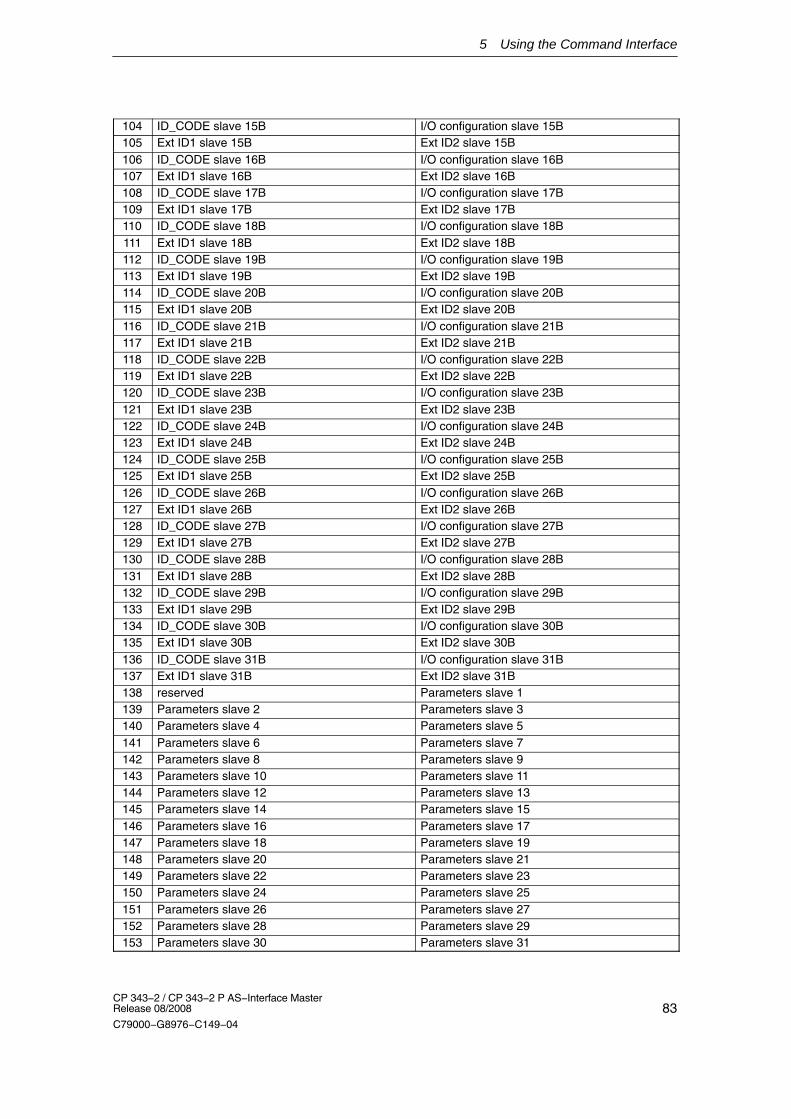
5 Using the Command Interface
83CP 343−2 / CP 343−2 P AS−Interface Master Release 08/2008
C79000−G8976−C149−04
104 ID_CODE slave 15B I/O configuration slave 15B105 Ext ID1 slave 15B Ext ID2 slave 15B106 ID_CODE slave 16B I/O configuration slave 16B107 Ext ID1 slave 16B Ext ID2 slave 16B108 ID_CODE slave 17B I/O configuration slave 17B109 Ext ID1 slave 17B Ext ID2 slave 17B110 ID_CODE slave 18B I/O configuration slave 18B111 Ext ID1 slave 18B Ext ID2 slave 18B112 ID_CODE slave 19B I/O configuration slave 19B113 Ext ID1 slave 19B Ext ID2 slave 19B114 ID_CODE slave 20B I/O configuration slave 20B115 Ext ID1 slave 20B Ext ID2 slave 20B116 ID_CODE slave 21B I/O configuration slave 21B117 Ext ID1 slave 21B Ext ID2 slave 21B118 ID_CODE slave 22B I/O configuration slave 22B119 Ext ID1 slave 22B Ext ID2 slave 22B120 ID_CODE slave 23B I/O configuration slave 23B121 Ext ID1 slave 23B Ext ID2 slave 23B122 ID_CODE slave 24B I/O configuration slave 24B123 Ext ID1 slave 24B Ext ID2 slave 24B124 ID_CODE slave 25B I/O configuration slave 25B125 Ext ID1 slave 25B Ext ID2 slave 25B126 ID_CODE slave 26B I/O configuration slave 26B127 Ext ID1 slave 26B Ext ID2 slave 26B128 ID_CODE slave 27B I/O configuration slave 27B129 Ext ID1 slave 27B Ext ID2 slave 27B130 ID_CODE slave 28B I/O configuration slave 28B131 Ext ID1 slave 28B Ext ID2 slave 28B132 ID_CODE slave 29B I/O configuration slave 29B133 Ext ID1 slave 29B Ext ID2 slave 29B134 ID_CODE slave 30B I/O configuration slave 30B135 Ext ID1 slave 30B Ext ID2 slave 30B136 ID_CODE slave 31B I/O configuration slave 31B137 Ext ID1 slave 31B Ext ID2 slave 31B138 reserved Parameters slave 1139 Parameters slave 2 Parameters slave 3140 Parameters slave 4 Parameters slave 5141 Parameters slave 6 Parameters slave 7142 Parameters slave 8 Parameters slave 9143 Parameters slave 10 Parameters slave 11144 Parameters slave 12 Parameters slave 13145 Parameters slave 14 Parameters slave 15146 Parameters slave 16 Parameters slave 17147 Parameters slave 18 Parameters slave 19148 Parameters slave 20 Parameters slave 21149 Parameters slave 22 Parameters slave 23150 Parameters slave 24 Parameters slave 25151 Parameters slave 26 Parameters slave 27152 Parameters slave 28 Parameters slave 29153 Parameters slave 30 Parameters slave 31

5 Using the Command Interface
84CP 343−2 / CP 343−2 P AS−Interface Master
Release 08/2008
C79000−G8976−C149−04
154 reserved Parameters slave 1B155 Parameters slave 2B Parameters slave 3B156 Parameters slave 4B Parameters slave 5B157 Parameters slave 6B Parameters slave 7B158 Parameters slave 8B Parameters slave 9B159 Parameters slave 10B Parameters slave 11B160 Parameters slave 12B Parameters slave 13B161 Parameters slave 14B Parameters slave 15B162 Parameters slave 16B Parameters slave 17B163 Parameters slave 18B Parameters slave 19B164 Parameters slave 20B Parameters slave 21B165 Parameters slave 22B Parameters slave 23B166 Parameters slave 24B Parameters slave 25B167 Parameters slave 26B Parameters slave 27B168 Parameters slave 28B Parameters slave 29B169 Parameters slave 30B Parameters slave 31B170 Flag 1171 Flag 2172 reserved... .....
218 reserved
Flag 1 Flag 2Bit Number Meaning Bit Number Meaning
0 OFFLINE_READY 0 OFFLINE1 APF 1 INTERNAL2 NORMAL_MODE 2 EEPROM_OK3 CONFIG_MODE 3 AUTO_ADDR_ENABLE4 AUTO_ADDR_AVAIL 4 PERIPHERY_FAULT5 AUTO_ADDR_ASSIGN 5 reserved6 LDS_0 6 reserved7 CONFIG_OK 7 MPO startup
The meaning of the flags is the same as for the Get_LPS, Get_LAS, Get_LDS,Get_Flags job.

5 Using the Command Interface
85CP 343−2 / CP 343−2 P AS−Interface Master Release 08/2008
C79000−G8976−C149−04
5.2.18 Store_Extended_Total_Configuration
Meaning
With this call, the required total configuration of the AS interface is transferred tothe AS-i master and stored permanently in the EEPROM as the expectedconfiguration. This configures the CP 343-2. The following data are transferred:
� The list of configured AS-i slaves specifying the AS-i slaves that can beactivated by the AS-i master in the protected mode.
� The list of configuration data specifying the ID codes and I/O configurations theAS-i slaves must have.
� The list of AS-i slave parameters configured on the AS-i master and stored innon-volatile memory. These parameters are transferred to the AS-i slaves whenthe AS-i master starts up.
� The flags that determine the operating status of the AS-i master following startup.
Up to firmware version V2.x, this call is not executed in protected mode.
As of firmware version V3.0, the call is permitted both in protected and inconfiguration mode.
For AS-i slaves that comply with the standard profile 7.4, the AS-i master managesthe parameter assignment itself. The parameter values for slaves complying withstandard profile 7.4 specified in the call are ignored by the AS-i master.
Structure of the Job Data in the Send Buffer
Byte Meaning
Bit 7 Bit 6 Bit 5 Bit 4 Bit 3 Bit 2 Bit 1 Bit 0
0 Command number: 3Ah
1 00h
2 reserved LPS slave1
LPS slave2
LPS slave3
LPS slave4
LPS slave5
LPS slave6
LPS slave7
3 LPS slave8
LPS slave9
LPS slave10
LPS slave11
LPS slave12
LPS slave13
LPS slave14
LPS slave15
4 LPS slave16
LPS slave17
LPS slave18
LPS slave19
LPS slave20
LPS slave21
LPS slave22
LPS slave23
5 LPS slave24
LPS slave25
LPS slave26
LPS slave27
LPS slave28
LPS slave29
LPS slave30
LPS slave31
6 reserved LPS slave1B
LPS slave2B
LPS slave3B
LPS slave4B
LPS slave5B
LPS slave6B
LPS slave7B
7 LPS slave8B
LPS slave9B
LPS slave10B
LPS slave11B
LPS slave12B
LPS slave13B
LPS slave14B
LPS slave15B

5 Using the Command Interface
86CP 343−2 / CP 343−2 P AS−Interface Master
Release 08/2008
C79000−G8976−C149−04
Byte Meaning
Bit 0Bit 1Bit 2Bit 3Bit 4Bit 5Bit 6Bit 7
8 LPS slave16B
LPS slave17B
LPS slave18B
LPS slave19B
LPS slave20B
LPS slave21B
LPS slave22B
LPS slave23B
9 LPS slave24B
LPS slave25B
LPS slave26B
LPS slave27B
LPS slave28B
LPS slave29B
LPS slave30B
LPS slave31B
10 ID_CODE slave 0 I/O configuration slave 011 Ext ID1 slave 0 Ext ID2 slave 012 ID_CODE slave 1 I/O configuration slave 113 Ext ID1 slave 1 Ext ID2 slave 114 ID_CODE slave 2 I/O configuration slave 215 Ext ID1 slave 2 Ext ID2 slave 216 ID_CODE slave 3 I/O configuration slave 317 Ext ID1 slave 3 Ext ID2 slave 318 ID_CODE slave 4 I/O configuration slave 419 Ext ID1 slave 4 Ext ID2 slave 420 ID_CODE slave 5 I/O configuration slave 521 Ext ID1 slave 5 Ext ID2 slave 522 ID_CODE slave 6 I/O configuration slave 623 Ext ID1 slave 6 Ext ID2 slave 624 ID_CODE slave 7 I/O configuration slave 725 Ext ID1 slave 7 Ext ID2 slave 726 ID_CODE slave 8 I/O configuration slave 827 Ext ID1 slave 8 Ext ID2 slave 828 ID_CODE slave 9 I/O configuration slave 929 Ext ID1 slave 9 Ext ID2 slave 930 ID_CODE slave 10 I/O configuration slave 1031 Ext ID1 slave 10 Ext ID2 slave 1032 ID_CODE slave 11 I/O configuration slave 1133 Ext ID1 slave 11 Ext ID2 slave 1134 ID_CODE slave 12 I/O configuration slave 1235 Ext ID1 slave 12 Ext ID2 slave 1236 ID_CODE slave 13 I/O configuration slave 1337 Ext ID1 slave 13 Ext ID2 slave 1338 ID_CODE slave 14 I/O configuration slave 1439 Ext ID1 slave 14 Ext ID2 slave 1440 ID_CODE slave 15 I/O configuration slave 1541 Ext ID1 slave 15 Ext ID2 slave 1542 ID_CODE slave 16 I/O configuration slave 1643 Ext ID1 slave 16 Ext ID2 slave 1644 ID_CODE slave 17 I/O configuration slave 1745 Ext ID1 slave 17 Ext ID2 slave 1746 ID_CODE slave 18 I/O configuration slave 1847 Ext ID1 slave 18 Ext ID2 slave 1848 ID_CODE slave 19 I/O configuration slave 1949 Ext ID1 slave 19 Ext ID2 slave 1950 ID_CODE slave 20 I/O configuration slave 2051 Ext ID1 slave 20 Ext ID2 slave 2052 ID_CODE slave 21 I/O configuration slave 2153 Ext ID1 slave 21 Ext ID2 slave 21

5 Using the Command Interface
87CP 343−2 / CP 343−2 P AS−Interface Master Release 08/2008
C79000−G8976−C149−04
54 ID_CODE slave 22 I/O configuration slave 2255 Ext ID1 slave 22 Ext ID2 slave 2256 ID_CODE slave 23 I/O configuration slave 2357 Ext ID1 slave 23 Ext ID2 slave 2358 ID_CODE slave 24 I/O configuration slave 2459 Ext ID1 slave 24 Ext ID2 slave 2460 ID_CODE slave 25 I/O configuration slave 2561 Ext ID1 slave 25 Ext ID2 slave 2562 ID_CODE slave 26 I/O configuration slave 2663 Ext ID1 slave 26 Ext ID2 slave 2664 ID_CODE slave 27 I/O configuration slave 2765 Ext ID1 slave 27 Ext ID2 slave 2766 ID_CODE slave 28 I/O configuration slave 2867 Ext ID1 slave 28 Ext ID2 slave 2868 ID_CODE slave 29 I/O configuration slave 2969 Ext ID1 slave 29 Ext ID2 slave 2970 ID_CODE slave 30 I/O configuration slave 3071 Ext ID1 slave 30 Ext ID2 slave 3072 ID_CODE slave 31 I/O configuration slave 3173 Ext ID1 slave 31 Ext ID2 slave 3174 0 075 0 076 ID_CODE slave 1B I/O configuration slave 1B77 Ext ID1 slave 1B Ext ID2 slave 1B78 ID_CODE slave 2B I/O configuration slave 2B79 Ext ID1 slave 2B Ext ID2 slave 2B80 ID_CODE slave 3B I/O configuration slave 3B81 Ext ID1 slave 3B Ext ID2 slave 3B82 ID_CODE slave 4B I/O configuration slave 4B83 Ext ID1 slave 4B Ext ID2 slave 4B84 ID_CODE slave 5B I/O configuration slave 5B85 Ext ID1 slave 5B Ext ID2 slave 5B86 ID_CODE slave 6B I/O configuration slave 6B87 Ext ID1 slave 6B Ext ID2 slave 6B88 ID_CODE slave 7B I/O configuration slave 7B89 Ext ID1 slave 7B Ext ID2 slave 7B90 ID_CODE slave 8B I/O configuration slave 8B91 Ext ID1 slave 8B Ext ID2 slave 8B92 ID_CODE slave 9B I/O configuration slave 9B93 Ext ID1 slave 9B Ext ID2 slave 9B94 ID_CODE slave 10B I/O configuration slave 10B95 Ext ID1 slave 10B Ext ID2 slave 10B96 ID_CODE slave 11B I/O configuration slave 11B97 Ext ID1 slave 11B Ext ID2 slave 11B98 ID_CODE slave 12B I/O configuration slave 12B99 Ext ID1 slave 12B Ext ID2 slave 12B100 ID_CODE slave 13B I/O configuration slave 13B101 Ext ID1 slave 13B Ext ID2 slave 13B102 ID_CODE slave 14B I/O configuration slave 14B103 Ext ID1 slave 14B Ext ID2 slave 14B

5 Using the Command Interface
88CP 343−2 / CP 343−2 P AS−Interface Master
Release 08/2008
C79000−G8976−C149−04
104 ID_CODE slave 15B I/O configuration slave 15B105 Ext ID1 slave 15B Ext ID2 slave 15B106 ID_CODE slave 16B I/O configuration slave 16B107 Ext ID1 slave 16B Ext ID2 slave 16B108 ID_CODE slave 17B I/O configuration slave 17B109 Ext ID1 slave 17B Ext ID2 slave 17B110 ID_CODE slave 18B I/O configuration slave 18B111 Ext ID1 slave 18B Ext ID2 slave 18B112 ID_CODE slave 19B I/O configuration slave 19B113 Ext ID1 slave 19B Ext ID2 slave 19B114 ID_CODE slave 20B I/O configuration slave 20B115 Ext ID1 slave 20B Ext ID2 slave 20B116 ID_CODE slave 21B I/O configuration slave 21B117 Ext ID1 slave 21B Ext ID2 slave 21B118 ID_CODE slave 22B I/O configuration slave 22B119 Ext ID1 slave 22B Ext ID2 slave 22B120 ID_CODE slave 23B I/O configuration slave 23B121 Ext ID1 slave 23B Ext ID2 slave 23B122 ID_CODE slave 24B I/O configuration slave 24B123 Ext ID1 slave 24B Ext ID2 slave 24B124 ID_CODE slave 25B I/O configuration slave 25B125 Ext ID1 slave 25B Ext ID2 slave 25B126 ID_CODE slave 26B I/O configuration slave 26B127 Ext ID1 slave 26B Ext ID2 slave 26B128 ID_CODE slave 27B I/O configuration slave 27B129 Ext ID1 slave 27B Ext ID2 slave 27B130 ID_CODE slave 28B I/O configuration slave 28B131 Ext ID1 slave 28B Ext ID2 slave 28B132 ID_CODE slave 29B I/O configuration slave 29B133 Ext ID1 slave 29B Ext ID2 slave 29B134 ID_CODE slave 30B I/O configuration slave 30B135 Ext ID1 slave 30B Ext ID2 slave 30B136 ID_CODE slave 31B I/O configuration slave 31B137 Ext ID1 slave 31B Ext ID2 slave 31B138 0 Parameters slave 1139 Parameters slave 2 Parameters slave 3140 Parameters slave 4 Parameters slave 5141 Parameters slave 6 Parameters slave 7142 Parameters slave 8 Parameters slave 9143 Parameters slave 10 Parameters slave 11144 Parameters slave 12 Parameters slave 13145 Parameters slave 14 Parameters slave 15146 Parameters slave 16 Parameters slave 17147 Parameters slave 18 Parameters slave 19148 Parameters slave 20 Parameters slave 21149 Parameters slave 22 Parameters slave 23150 Parameters slave 24 Parameters slave 25151 Parameters slave 26 Parameters slave 27152 Parameters slave 28 Parameters slave 29153 Parameters slave 30 Parameters slave 31

5 Using the Command Interface
89CP 343−2 / CP 343−2 P AS−Interface Master Release 08/2008
C79000−G8976−C149−04
154 reserved Parameters slave 1B155 Parameters slave 2B Parameters slave 3B156 Parameters slave 4B Parameters slave 5B157 Parameters slave 6B Parameters slave 7B158 Parameters slave 8B Parameters slave 9B159 Parameters slave 10B Parameters slave 11B160 Parameters slave 12B Parameters slave 13B161 Parameters slave 14B Parameters slave 15B162 Parameters slave 16B Parameters slave 17B163 Parameters slave 18B Parameters slave 19B164 Parameters slave 20B Parameters slave 21B165 Parameters slave 22B Parameters slave 23B166 Parameters slave 24B Parameters slave 25B167 Parameters slave 26B Parameters slave 27B168 Parameters slave 28B Parameters slave 29B169 Parameters slave 30B Parameters slave 31B170 Flag 1171 Flag 2
Flag 1 Flag 2Bit Number Meaning Bit Number Meaning0 OFFLINE_READY 0 OFFLINE1 APF 1 INTERNAL2 NORMAL_MODE 2 EEPROM_OK3 CONFIG_MODE 3 AUTO_ADDR_ENABLE4 AUTO_ADDR_AVAIL 4 PERIPHERY_FAULT5 AUTO_ADDR_ASSIGN 5 06 LDS_0 6 07 CONFIG_OK 7 MPO startup
Flags whose values modify the AS-i master mode are shown in gray. The values ofthe other flags have no significance for the ‘store total configuration’ command andcannot be modified on the AS-i master with this call.
CONFIG_MODE The entry ‘0’ means that the AS-i master changes to the protected modeafter executing the command. The entry ‘1’ means that the configurationmode is retained.
0: On completion of the job, the AS-i master starts up in the protected mode.
1: On completion of the job, the AS-i master starts up in the configurationmode..
AUTO_ADDR_ENABLE ’0’ means that the automatic address programming is disabled, ’1’ meansthat the automatic address programming is enabled.
0: Automatic address programming disabled.
1: Address programming enabled

5 Using the Command Interface
90CP 343−2 / CP 343−2 P AS−Interface Master
Release 08/2008
C79000−G8976−C149−04
5.2.19 Write_Extended_Parameter_List
Meaning
With this command, the parameters for all slaves are transferred to the AS-imaster. The AS-i master transfers only the parameters that have changed; inother words, that differ from the previously set (actual) parameters to theAS-i slaves.
Structure of the Job Data in the Send Buffer
Byte MeaningBit 7 Bit 6 Bit 5 Bit 4 Bit 3 Bit 2 Bit 1 Bit 0
0 Command number: 3C H1 00H
2 irrelevant Parameters slave 13 Parameters slave 2 Parameters slave 34 Parameters slave 4 Parameters slave 55 Parameters slave 6 Parameters slave 76 Parameters slave 8 Parameters slave 97 Parameters slave 10 Parameters slave 118 Parameters slave 12 Parameters slave 139 Parameters slave 14 Parameters slave 15
10 Parameters slave 16 Parameters slave 1711 Parameters slave 18 Parameters slave 1912 Parameters slave 20 Parameters slave 2113 Parameters slave 22 Parameters slave 2314 Parameters slave 24 Parameters slave 2515 Parameters slave 26 Parameters slave 2716 Parameters slave 28 Parameters slave 2917 Parameters slave 30 Parameters slave 3118 irrelevant Parameters slave 1B19 Parameters slave 2B Parameters slave 3B20 Parameters slave 4B Parameters slave 5B21 Parameters slave 6B Parameters slave 7B22 Parameters slave 8B Parameters slave 9B23 Parameters slave 10B Parameters slave 11B24 Parameters slave 12B Parameters slave 13B25 Parameters slave 14B Parameters slave 15B26 Parameters slave 16B Parameters slave 17B27 Parameters slave 18B Parameters slave 19B28 Parameters slave 20B Parameters slave 21B29 Parameters slave 22B Parameters slave 23B30 Parameters slave 24B Parameters slave 25B31 Parameters slave 26B Parameters slave 27B32 Parameters slave 28B Parameters slave 29B33 Parameters slave 30B Parameters slave 31B
5 Using the Command Interface
91CP 343−2 / CP 343−2 P AS−Interface Master Release 08/2008
C79000−G8976−C149−04
5.2.20 Read_Extended_Parameter_Echo_List
Meaning
The read parameter echo list call outputs the echo values of all AS-i slaves. Theecho values of an AS-i slave originate from the last parameter call sent to this AS-islave.
Structure of the Job Data in the Send Buffer
Byte Meaning0 Command number: 33h1 00h
Structure of the Response Data in the Receive Buffer
Byte MeaningBit 7 Bit 6 Bit 5 Bit 4 Bit 3 Bit 2 Bit 1 Bit 0
1 irrelevant Par echo slave 12 Par echo slave 2 Par echo slave 33 Par echo slave 4 Par echo slave 54 Par echo slave 6 Parameters slave 76 Par echo slave 8 Par echo slave 95 Par echo slave 10 Par echo slave 116 Par echo slave 12 Par echo slave 137 Par echo slave 14 Par echo slave 158 Par echo slave 16 Par echo slave 179 Par echo slave 18 Par echo slave 1910 Par echo slave 20 Par echo slave 2111 Par echo slave 22 Par echo slave 2312 Par echo slave 24 Par echo slave 2513 Par echo slave 26 Par echo slave 2714 Par echo slave 28 Par echo slave 2915 Par echo slave 30 Par echo slave 3116 irrelevant Par echo slave 1B17 Par echo slave 2B Par echo slave 3B18 Par echo slave 4B Par echo slave 5B19 Par echo slave 6B Parameters slave 7B20 Par echo slave 8B Par echo slave 9B21 Par echo slave 10B Par echo slave 11B22 Par echo slave 12B Par echo slave 13B23 Par echo slave 14B Par echo slave 15B24 Par echo slave 16B Par echo slave 17B25 Par echo slave 18B Par echo slave 19B26 Par echo slave 20B Par echo slave 21B27 Par echo slave 22B Par echo slave 23B28 Par echo slave 24B Par echo slave 25B29 Par echo slave 26B Par echo slave 27B30 Par echo slave 28B Par echo slave 29B31 Par echo slave 30B Par echo slave 31B

5 Using the Command Interface
92CP 343−2 / CP 343−2 P AS−Interface Master
Release 08/2008
C79000−G8976−C149−04
5.2.21 Read_Write_CTT2_request
Meaning
Using this call, a CTT2 request according to AS-i slave profile“CombinedTranslationType2” can be sent to the AS-i master as a byte string. Thisforwards the string bytes to the AS-i slave address specified in the send buf fer.
With this call, a send buffer with a maximum of 223 bytes is transferred to the AS-imaster. The actual number of string bytes to be sent to the AS-i slave is calculatedby the AS-i master from byte 2 of the send buf fer (number of string bytes).
The CTT2 request is replied to by the addressed AS-i slave with a CTT2 response.The AS-i master transfers this response as a byte string in the response buf fer.The strings are transferred by the AS−i master with the response.
The structure of the CTT2 request or CTT2 response (code, index, ...) alwaysbegins with string byte 1. For more detailed information, refer to the relevant AS-islave description.
As long as strings are being transferred on AS-i, there is no cyclic data transferwith the addresses AS-i slave. Due to the type of protocol, the transfer of approximately 200 bytes can take up tohalf a minute.
Structure of the Job Data in the Send Buffer
Byte Meaning
0 Command number: 44 H1 Slave address
2 Number of string bytes
3 String byte 1
4 String byte 2
... ...
... String byte (n−1)
... (String byte n)
Structure of the Response Data in the Receive Buffer
Byte Meaning
0 Number of string bytes
1 String byte (1)
2 String byte (2)
... .....
String byte (n-1)
... String byte (n)

5 Using the Command Interface
93CP 343−2 / CP 343−2 P AS−Interface Master Release 08/2008
C79000−G8976−C149−04
5.2.22 Read_Version_ID
Meaning
This call reads out the version ID of the firmware of the AS-i master .
Structure of the Job Data in the Send Buffer
Byte Meaning
0 Command number: 14H
The response of the AS-i master contains the name and the firmware versionnumber.
Structure of the Response Data in the Receive Buffer
Byte Meaning
0...31 Version string

5 Using the Command Interface
94CP 343−2 / CP 343−2 P AS−Interface Master
Release 08/2008
C79000−G8976−C149−04
5.2.23 Read_AS-i_Slave_ID
Meaning
With this call, the ID code of an AS-i slave can be read out directly over the AS-icable. The call is intended for diagnostic purposes and is not required in the normalmaster mode.
Structure of the Job Data in the Send Buffer
Byte Meaning
0 Command number: 17H
1 Slave address
Structure of the Response Data in the Receive Buffer
Byte Meaning
Bit 7 Bit 4 Bit 3 Bit 0
0 reserved ID code

5 Using the Command Interface
95CP 343−2 / CP 343−2 P AS−Interface Master Release 08/2008
C79000−G8976−C149−04
5.2.24 Read_AS-i_Slave_Extended_ID1
Meaning
With this call, the extended ID1 code of an AS-i slave can be read out directly overthe AS-i cable. The call is intended for diagnostic purposes and is not required inthe normal master mode.
Structure of the Job Data in the Send Buffer
Byte Meaning
0 Command number: 37H
1 Slave address
Structure of the Response Data in the Receive Buffer
Byte Meaning
Bit 7 Bit 4 Bit 3 Bit 0
0 reserved Extended ID1 code

5 Using the Command Interface
96CP 343−2 / CP 343−2 P AS−Interface Master
Release 08/2008
C79000−G8976−C149−04
5.2.25 Write_AS-i_Slave_Extended_ID1
Meaning
With this call, the extended ID1 code of an AS-i slave with address “0” can bewritten directly over the AS-i cable. The call is intended for diagnostic purposesand is not required in the normal master mode.
The AS-i master passes on the extended ID1 code to the AS-i slave without anyplausibility check.
Structure of the Job Data in the Send Buffer
Byte Meaning
0 Command number: 3FH
1 irrelevant Extended ID1 code

5 Using the Command Interface
97CP 343−2 / CP 343−2 P AS−Interface Master Release 08/2008
C79000−G8976−C149−04
5.2.26 Read_AS-i_Slave_Extended_ID2
Meaning
With this call, the extended ID2 code of an AS-i slave can be read out directly overthe AS-i cable. The call is intended for diagnostic purposes and is not required inthe normal master mode.
Structure of the Job Data in the Send Buffer
Byte Meaning
0 Command number: 38H
1 Slave address
Structure of the Response Data in the Receive Buffer
Byte Meaning
Bit 7 Bit 4 Bit 3 Bit 0
0 reserved Extended ID2 code

5 Using the Command Interface
98CP 343−2 / CP 343−2 P AS−Interface Master
Release 08/2008
C79000−G8976−C149−04
5.2.27 Read_AS-i_Slave_I/O
Meaning
With this call, the I/O configuration of an AS-i slave can be read out directly overthe AS-i cable. The call is intended for diagnostic purposes and is not required inthe normal master mode.
Structure of the Job Data in the Send Buffer
Byte Meaning
0 Command number: 18
1 Slave address
Structure of the Response Data in the Receive Buffer
Byte Meaning
Bit 7 Bit 4 Bit 3 Bit 0
0 reserved I/O configuration

5 Using the Command Interface
99CP 343−2 / CP 343−2 P AS−Interface Master Release 08/2008
C79000−G8976−C149−04
5.2.28 Get_LPF
Meaning
With this call, the list of peripheral faults (LPF) signaled by the AS-i slaves is readout from the AS-i master. The LPF is updated cyclically by the AS-i master.Whether and when as AS-i slave signals faults of the attached peripherals (forexample wire break) can be found in the description of the AS-i slave.
Structure of the Job Data in the Send Buffer
Byte Meaning
0 Command number 3E H
Structure of the Replies in the Receive Buffer
Byte Meaning
Bit 7 Bit 6 Bit 5 Bit 4 Bit 3 Bit 2 Bit 1 Bit 0
0 Slave 0 Slave 1 Slave 2 Slave 3 Slave 4 Slave 5 Slave 6 Slave 7
1 Slave 8 Slave 9 Slave 10 Slave 11 Slave 12 Slave 13 Slave 14 Slave 15
2 Slave 16 Slave 17 Slave 18 Slave 19 Slave 20 Slave 21 Slave 22 Slave 23
3 Slave 24 Slave 25 Slave 26 Slave 27 Slave 28 Slave 29 Slave 30 Slave 31
4 Slave 0B Slave 1B Slave 2B Slave 3B Slave 4B Slave 5B Slave 6B Slave 7B
5 Slave 8B Slave 9B Slave 10B Slave 11B Slave 12B Slave 13B Slave 14B Slave 15B
6 Slave 16B Slave 17B Slave 18B Slave 19B Slave 20B Slave 21B Slave 22B Slave 23B
7 Slave 2B4 Slave 25B Slave 26B Slave 27B Slave 28B Slave 29B Slave 30B Slave 31B
8 reserved
... reserved
13 reserved
For the LPF data, the bit values have the following meaning:
Bit=0: Slave signals no peripheral faultBit=1: Slave signals peripheral fault.

5 Using the Command Interface
100CP 343−2 / CP 343−2 P AS−Interface Master
Release 08/2008
C79000−G8976−C149−04
5.2.29 Write_AS-i_Slave_Parameter_String
Meaning
With this call, a parameter string complying with AS-i slave profile 7.4 can be sentto the AS-i master that passes on the string to the AS-i slave address specified inthe send buffer.
With this call, a send buffer with a maximum of 223 bytes is transferred to the AS-imaster. The actual number of parameter bytes to be sent to the AS-i slave iscalculated by the AS-i master from byte 2 of the send buf fer (number of parameterbytes).
The remaining information in the string is not evaluated by the AS-i master and ispassed on to the AS-i slave transparently. As long as the string transfer is active,there is no user/analog data exchange with the addressed AS-i slave.
Structure of the Job Data in the Send Buffer
Byte Meaning
0 Command number: 40 H
1 Slave address
2 Number of parameter bytes
3 String byte (1)
4 String byte (2)
... .....
String byte (n-1)
... String byte (n)
Maximum value for n=220

5 Using the Command Interface
101CP 343−2 / CP 343−2 P AS−Interface Master Release 08/2008
C79000−G8976−C149−04
5.2.30 Read_AS-i_Slave_Parameter_String
Meaning
With this call, a parameter string complying with AS-i slave profile 7.4 can be readfrom the AS-i slave with the AS-i slave address specified in the send buffer.
The AS-i master supplies up to 221 bytes of response data. The number ofparameter bytes actually sent by the AS-i slave is signaled by the AS-I master inbyte 0 of the receive buffer (number of parameter bytes).
If the AS-i slave sends a string longer than 220 bytes, the AS-i master aborts thestring transfer and terminates the job with an error. The received data are then notmade available to the user program.
As long as the string transfer is active, there is no user/analog data exchange withthe addressed AS-i slave.
Structure of the Job Data in the Send Buffer
Byte Meaning
0 Command number 41H
1 Slave address
Structure of the Response Data in the Receive Buffer
Byte Meaning
0 Number of parameter bytes
1 String byte (1)
2 String byte (2)
... .....
String byte (n-1)
... String byte (n)
Maximum value for n=220

5 Using the Command Interface
102CP 343−2 / CP 343−2 P AS−Interface Master
Release 08/2008
C79000−G8976−C149−04
5.2.31 Read_AS-i_Slave_ID_String
Meaning
With this call, an identification string complying with the AS-i slave profile 7.4 canbe read from the AS-i slave with the AS-i slave address specified in the sendbuffer. The AS-i master supplies up to 221 bytes of response data. The number ofID bytes actually sent by the AS-i slave is signaled by the AS-i master in byte 0 ofthe receive buffer (number of ID bytes).
If the AS-i slave sends a string longer than 220 bytes, the AS-i master aborts thestring transfer and terminates the job with an error. The received data are then notmade available to the user program.
As long as the string transfer is active, there is no user/analog data exchange withthe addressed AS-i slave.
Note
As an exception, with this call, the bytes contained in the bits “Follows” and “Valid”are also transferred (see AS-i slave profile 7.4).
Structure of the Job Data in the Send Buffer
Byte Meaning
0 Command number 42H
1 Slave address
Structure of the Response Data in the Receive Buffer
Byte Meaning
0 Number of ID bytes
1 String byte (1)
2 String byte (2)
... .....
... String byte (n-1)
... String byte (n)
Maximum value for n=220

5 Using the Command Interface
103CP 343−2 / CP 343−2 P AS−Interface Master Release 08/2008
C79000−G8976−C149−04
5.2.32 Read_AS-i_Slave_Diagnostic_String
Meaning
With this call, a diagnostic string complying with AS-i slave profile 7.4 can be readfrom the AS-i slave with the AS-i slave address specified in the send buffer. TheAS-i master supplies up to 221 bytes of response data. The number of diagnosticbytes actually sent by the AS-i slave is signaled by the AS-i master in byte 0 of thereceive buffer (number of diagnostic bytes).
If the AS-i slave sends a string longer than 220 bytes, the AS-i master aborts thestring transfer and terminates the job with an error. The received data are then notmade available to the user program.
As long as the string transfer is active, there is no user/analog data exchange withthe addressed AS-i slave.
Structure of the Job Data in the Send Buffer
Byte Meaning
0 Command number 43H
1 Slave address
Structure of the Response Data in the Receive Buffer
Byte Meaning
0 Number of diagnostic bytes
1 String byte (1)
2 String byte (2)
... .....
... String byte (n-1)
... String byte (n)
Maximum value for n=220
�

104CP 343−2 / CP 343−2 P AS−Interface Master
Release 08/2008
C79000−G8976−C149−04
6 Diagnostics and Interrrupts of the CP 343-2
In the protected mode, the CP 343-2 signals a diagnostic interrupt whenever theconfiguration on the AS-Interface is changed. Changes in the configuration mightbe that voltage on the AS-Interface is too low (AS-i Power Fail) or thatconfiguration errors have been detected (missing, incorrect or existing butunconfigured AS-i slaves).
6.1 Overview
If the CP 343-2 detects an external or internal fault/error (AS-i slave failures,EEPROM error on the CP, ...) during operation, it signals this by triggering adiagnostic interrupt on the S7 I/O bus.The S7 CPU then interrupts the cyclic user program (OB1), enters the event as“module fault” in the system diagnostic buffer and behaves as follows:
� If the user has not programmed a suitable interrupt OB (OB82), the PLC CPUchanges to the STOP mode!
� If the user has programmed OB 82, this is started by the PLC operatingsystem. The local data of OB 82 already provides the user with a certainamount of diagnostic information. (Which module triggered the interrupt. Whattype of error has occurred ...). The user program can obtain more detailedinformation (which slave has failed? ...) by reading the diagnostic data recordDS 1 using the system functions SFC 51 (”RDSYSST”) or SFC 59 (”RD_REC”).When OB82 has been executed, the PLC continues the cyclic program (OB1)at the point at which it was interrupted.
Note
OB82 cannot be programmed on the CPU 312; in other words, if a diagnosticinterrupt occurs, the CPU changes to the STOP mode.
6.2 Interrupt Events
The CP 343-2 distinguishes between interrupt events entering and leaving thestate. If the occurrence of an interrupt event leads to an error-free status, adiagnostic interrupt leaving state is triggered (in OB 82: Bit OB82_MDL_DEFECT= 0). All other interrupt events result in a diagnostic interrupt entering state (BitOB82_MDL_DEFECT = 1).
The following events can lead to a diagnostic interrupt being triggered by the CP343-2:

6 Diagnostics and Interrrupts of the CP 343-2
105CP 343−2 / CP 343−2 P AS−Interface Master Release 08/2008
C79000−G8976−C149−04
� All changes to the AS-i slave configuration in the protected mode
� AS-i Power Fail in the protected mode
CP-internal interrupt events:
� EEPROM Error
Note
CP-internal interrupt events are always events entering the state. After aCP-internal interrupt event occurs, the group error bit remains = TRUE. This isonly reset again after a restart on the S7-300.
6.3 Sequence of Diagnostic Interrupt Processing
If the CP 343-2 detects an interrupt event, it triggers a diagnostic interrupt. ThePLC CPU finds the source of the interrupt and reads data record 0 from the CP. Itthen interrupts the cyclic user program and behaves as follows:
� If OB82 is not programmed, the PLC CPU changes to STOP as the defaultreaction.
� If organization block OB82 his programmed, this is started. DS 0 is available inthe local data bytes 8 to 11 in the local data area of OB82. It is possible (but notnecessary) to read DS 1 that contains the delta list in OB82 using an SFC call(SFC 51 “RDSYSST” or SFC 59 ”RD_REC”). When OB has been executed, thePLC CPU acknowledges the diagnostic interrupt on the CP 342-2.
If interrupt events occur in a status in which they cannot be signaled by triggering adiagnostic interrupt (for example, when the PLC is in the STOP mode or when anolder diagnostic interrupt is not yet been acknowledged), the CP 343-2 behaves asfollows:
� As soon as it becomes possible to trigger a diagnostic interrupt again, and if thetotal CP configuration (in other words, AS-i slave configuration and CP-internal,interrupt-relevant state) at this point in time is not the same as the configurationsignaled earlier with the diagnostic interrupt, a diagnostic interrupt with thecurrent configuration information is triggered.
� When it becomes possible again to trigger a diagnostic interrupt and if the totalCP configuration is the same as signaled earlier with the diagnostic interrupt, nodiagnostic interrupt is triggered. This means that brief slave failures (forexample, a bad contact) can go unnoticed.
CP-external interrupt events:

6 Diagnostics and Interrrupts of the CP 343-2
106CP 343−2 / CP 343−2 P AS−Interface Master
Release 08/2008
C79000−G8976−C149−04
6.4 Response to Interrupts in Different CP Operating States
The CP 343-2 generates diagnostic interrupts triggered by external interrupt eventsonly in the protected mode and not in the configuration mode.
If the PLC CPU changes to STOP, the internal interrupt history is reset; in otherwords, the bit OB82_MDL_DEFECT and all other error bits in DS 0 are reset.
If there is a change from the protected mode to the configuration mode, theexternal interrupt history is reset. If the CP 343-2 changes from the configurationmode to the protected mode and if there is a configuration error at this point intime, this is signaled with a diagnostic interrupt. If it is temporarily not possible toissue a diagnostic interrupt (for example, because the PLC is in the STOP mode),a diagnostic interrupt is generated at the next possible time only if the problem stillexists.
6.5 Local Data of the Diagnostic Organization Block (OB82)
The following table shows the DS 0 available in the local data of OB82 (local byte 8to local byte 11). For the meaning of the other OB82 local data, please refer to theSTEP 7 descriptions.
Byte Bit Variable Name Data Type Meaning
8 20 OB82_MDL_DEFECT BOOL Group error bit (0: interrupt leavingstate, 1: interrupt entering state)
8 21 OB82_INT_FAULT BOOL Internal CP error (for exampleEEPROM defective).
8 22 OB82_EXT_FAULT BOOL External CP error (for example slavefailed or APF).
8 23 OB82_PNT_INFO BOOL At least one slave differs from theexpected configuration.
8 24 OB82_EXT_VOLTAGE BOOL Voltage on the AS-Interface too low(APF).
8 25 OB82_FLD_CONNCTR BOOL with the CP 343-2 always 0
8 26 OB82_NO_CONFIG BOOL with the CP 343-2 always 0
8 27 OB82_CONFIG_ERR BOOL with the CP 343-2 always 0
9 20...23
OB82_MDL_TYPE − Module class, for CP 343–2: C hex
9 24 OB82_MDL_TYPE BOOL with the CP 343-2 always 1
9 25 OB82_MDL_TYPE BOOL reserved

6 Diagnostics and Interrrupts of the CP 343-2
107CP 343−2 / CP 343−2 P AS−Interface Master Release 08/2008
C79000−G8976−C149−04
Byte MeaningData TypeVariable NameBit
9 26 OB82_MDL_TYPE BOOL � with the CP with firmware V2.x:always “0”
� with the CP as of firmware V3.0:at least 1 AS−i slave is signalingan IO error.
9 27 OB82_MDL_TYPE BOOL reserved
10 20 OB82_SUB_NDL_ERR BOOL At least one slave differs from theexpected configuration.
10 21 OB82_COMM_FAULT BOOL with the CP 343-2 always 0
10 22 OB82_MDL_STOP BOOL 0: CP 343-2 is in the normal state,
1: CP 343-2 is in the offline state
10 23 OB82_WTCH_DOG_FLT BOOL Hardware error on the CP (internalwatchdog)
10 24 OB82_INT_PS_FLT BOOL with the CP 343-2 always 0
10 25 OB82_PRIM_BATT_FLT BOOL with the CP 343-2 always 0
10 26 OB82_BCKUP_BATT_FLT BOOL with the CP 343-2 always 0
10 27 OB82_RESERVED_2 BOOL with the CP 343-2 always 0
11 20 OB82_RACK_FLT BOOL with the CP 343-2 always 0
11 21 OB82_PROC_FLT BOOL with the CP 343-2 always 0
11 22 OB82_EPROM_FLT BOOL EEPROM of the CP 343-2 defective
11 23 OB82_RAM_FLT BOOL with the CP 343-2 always 0
11 24 OB82_ADU_FLT BOOL with the CP 343-2 always 0
11 25 OB82_FUSE_FLT BOOL with the CP 343-2 always 0
11 26 OB82_RESERVED_3 BOOL with the CP 343-2 always 0

6 Diagnostics and Interrrupts of the CP 343-2
108CP 343−2 / CP 343−2 P AS−Interface Master
Release 08/2008
C79000−G8976−C149−04
6.6 Reading the Diagnostic Data Record DS 1
The CP 343-2 continuously updates a delta list containing all the slaves that existbut that differ from the configuration; in other words, they are missing, incorrect, ornot configured (each slave is assigned a bit in the delta list: 0 = no error; 1 = error).This delta list is part of the diagnostic data record DS1 that can be read out bycalling the operating system functions SFC 51 “RDSYSST” or SFC 59 ”RD_REC”.
To optimize the time at which DS1 is read, it is advisable to use SFC 51.
On the CP 343-2, DS 1 always has a length of 16 bytes and is structured asfollows:
Byte Value/meaning
0−3 These four bytes contain DS 0 and correspond to the local data bytes 8to 11 in OB82.
Byte Value Purpose
4 60H Fixed value
5 00H Fixed value
6 40H Fixed value
Byte Bit *) Value/meaning *)
7 0..7 1: error in AS-i slave 0.. 7
8 0..7 1: error in AS-i slave 8..15
9 0..7 1: error in AS-i slave 16..23
10 0..7 1: error in AS-i slave 24..31
11 0..7 1: error in AS-i slave 0B.. 7B
12 0..7 1: error in AS-i slave 8B..15B
13 0..7 1: error in AS-i slave 16B..23B
14 0..7 1: error in AS-i slave 24B..31B
15 reserved
*) Bit 0 belongs to slave 0, bit 1 belongs to slave 1 etc.
After the programming example, Section 6.7 contains an example of evaluating thedelta list.

6 Diagnostics and Interrrupts of the CP 343-2
109CP 343−2 / CP 343−2 P AS−Interface Master Release 08/2008
C79000−G8976−C149−04
6.7 Programming Example
The following example illustrates how you can react to a diagnostic interrupt of theCP 343-2 in OB82 by reading the data record (DS1).
Table 8-1
STL Explanation
OB82 local data:
20.0 temp t_header Struct+0.0 temp len WORD+2.0 temp nr WORD=4.0 temp END_STRUCT
OB82 Code:
L 256L #OB82_MDL_ADDR<>IBECCALL “RDSYSST”REQ :=TRUESZL_ID :=W#16#B3INDEX :=W#16#100RET_VAL :=MW18BUSY :=M9.4SZL_HEADER :=#t_headerDR :=P#M 100.0 Byte 16
//Example of an error reaction
0 M107.10 M107.70 M111.3= M9.5
//No relevance for the CP 343-2
//Address of the CP 343-2//Interrupt from the CP 343-2
//DS1 via logical base address//CP address (256 dec.)
//Structure of the local data//Destination for DS1
//Error: slave 1//Error: slave 7//Error: slave 3B//Error bit

6 Diagnostics and Interrrupts of the CP 343-2
110CP 343−2 / CP 343−2 P AS−Interface Master
Release 08/2008
C79000−G8976−C149−04
6.8 Diagnostic Interrupts: Some Examples
It is assumed that slaves 1 and 12 were configured using the buttons on the CP343-2 and that the CP 343-2 is in the protected mode.
If slave 7 fails, the CP 343-2 generates a diagnostic interrupt. The PLC operatingsystem then enters the “module fault” message in the system diagnostic buf fer andstarts OB82 (refer to the programming example in Section 6.7). When OB82 hasbeen executed, the delta list contains the following information:
MD 107 80 00 00 00HMD 111 00 00 00 00H
If the unconfigured slave 15 is then connected to the AS-interface, the CP 343-2generates another diagnostic interrupt. The “module fault” message appears in thesystem diagnostic buffer again.The delta list then changes to the following value:
MD 107 80 80 00 00HMD 111 00 00 00 00H
After reconnecting slave 7 to the AS-interface, there is still an error (slave 15). The“module fault” message appears in the system diagnostic buffer and the delta listhas the following value:
MD 107 00 80 00 00HMD 111 00 00 00 00H
After disconnecting slave 15, no error exists any longer. The CP 343-2 signals thisin the diagnostic interrupt. The “module OK” appears in the system diagnosticbuffer and the Delta list is empty:
MD 107 00 00 00 00HMD 111 00 00 00 00H
�

111CP 343−2 / CP 343−2 P AS−Interface Master Release 08/2008
C79000−G8976−C149−04
7 Dealing with Problems / Error Displays
This chapter contains information about special operating states of the CP 343-2. Itis intended to help you to deal with problems.
7.1 Replacing a Defective AS-i Slave/Automatic AddressProgramming
Simple Replacement of AS-i Slaves
Using the automatic address programming function, you can replace failed AS-islaves extremely simply.
Note
Remember that “automatic address programming” is only possible when the CP343-2 is in the protected mode and only one AS-i slave has failed.
Slaves with profile CTT5 (multiaddress slaves) do not support automatic addressprogramming.
The sections below explain how to replace failed AS-i slaves using the automaticaddress programming function.
Detecting a Defective AS-i Slave
If the AUP LED is lit (only in the protected mode) this indicates the following:
� Exactly one slave has failed.
� Automatic address programming by the CP 343-2 is possible.
You can recognize the failed AS-i slave simply because the LED assigned to theslave flashes on the front panel.
Replacing a Defective AS-i Slave
� Replace the defective AS-i slave with an identical AS-i slave with addresszero (default address).
The CP 343-2 then programs this slave with the address of the original station thathad failed.
The “AUP” display goes off. The LED in the slave display of the CP 343-2 moduleindicates that the slave has been included.

7 Dealing with Problems / Error Displays
112CP 343−2 / CP 343−2 P AS−Interface Master
Release 08/2008
C79000−G8976−C149−04
7.2 Error Displays/Remedying Errors
The following table lists the possible causes of errors that can occur whenoperating the CP 343-2 and how to remedy the problem.
Table 10-1
Error Possible Cause Remedy
APF LED lit Power requirements of the AS-islaves are too high. Result: Thevoltage on the AS-i cable is toolow.
Check the power requirements ofthe AS-i slaves. If necessary, sup-ply the AS-i slaves with an exter-nal voltage.
Power requirements of the AS-islave too high.
Check the power requirements ofthe AS-i slaves. If necessary,supply the slaves with powerexternally.
PWR LED not lit The CP connection to thebackplane bus is faulty.
Check whether the module isplugged in correctly.
SF lights up without pressing thebutton.
The CP 342−2 is in the protectedmode and an AS-i configurationerror has occurred (for exampleslave failure).
Eliminate the configuration error.
The CP is defective. Internal EEPROM error −> see signalingS7−300 system diagnostic buffer.
Replace the CP.
SF is lit when the SET button ispressed.
A slave with address 0 existswhen there is a change to the pro-tected mode.
Remove the slave with address 0from the AS-i cable.
CER LED is permanently lit. The CP 343-2 module has not yetbeen configured.
Configure the CP 343-2 moduleusing the SET button on the frontpanel.
A configured AS-i slave has failed(evaluate the slave display).
Replace the defective AS-i slaveor reconfigure the CP 343-2 mo-dule if the AS-i slave is not requi-red.
An unconfigured slave was con-nected to the AS-i cable.
Remove the AS-i slave or reconfi-gure the CP 343-2 module.
An AS-i slave was connectedwhose configuration data (I/O con-figuration, ID code) do not matchthe values of the configured AS-islave.
Check whether the wrong slavehas been connected. If necessary,reconfigure the CP 343-2.
Short circuit on the AS-i cable Check the AS-i cable and the con-nected AS-i slaves.

7 Dealing with Problems / Error Displays
113CP 343−2 / CP 343−2 P AS−Interface Master Release 08/2008
C79000−G8976−C149−04
Table 10-1 , continued
Error RemedyPossible Cause
The CER display flickers, in otherwords a configured slave is lostsporadically.
Bad contact Check the electrical connectionsof the AS-i slaves.
sporadically.Interference on the AS-i cable. Check the correct grounding of
the CP 343-2 module and checkthe AS-i cable. Check that theshield of the AS-i power supplyunit is connected correctly.
The CP 343-2 does not switchfrom the configuration mode to
The PLC is in the “RUN” mode. Switch the PLC to “STOP”.from the configuration mode tothe protected mode.
The SET button was not pressedlong enough.
Press the SET button for at least0.5 seconds.
An AS-i slave with address 0 isconnected to the AS-i cable.The CP 343-2 cannot change tothe protected mode as long asthis slave exists.
Remove the AS-i slave with ad-dress 0.
The CP 343-2 does not switchfrom the protected mode to the
The PLC is in the “RUN” mode. Switch the PLC to “STOP”.from the protected mode to theconfiguration mode.
The SET button was not pressedlong enough.
Press the SET button for at least0.5 seconds.
After failure of an AS-i slave, the“AUP” display remains off.
The CP 343-2 is in the configura-tion mode.
”Automatic Programming” is notpossible in the configurationmode.Program the address of the newAS-i slave with the address pro-grammer or using the commandinterface of the CP 343-2.
More than one AS-i slave has fai-led.
Check the AS-i cable.If “APF” is displayed at the sametime, check the power supply onthe AS-i cable.If more than one slave is defec-tive, program the address on thereplaced slaves using the addres-sing unit.
The CP 343-2 has not detectedconfigured AS-i slaves.
Remove the unconfigured AS-islaves from the AS-i cable.
The AUTO_ADDRESS_ENABLEflag is not set.
Set the bit with the appropriateFC calls
Automatic address programmingis unsuccessful although the“AUP” display is lit.
The configuration data (I/O confi-guration, ID code) of the replacedAS-i slave do not match the va-lues of the original slave.
Check whether the correct “repla-cement slave” was used.Compare the information from themanufacturer about configurationdata.If you want to replace the originalslave with a different type, assignthe address with the addressingunit and reconfigure the CP 343-2module (with the SET button).
The replaced AS-i slave does nothave the address “ZERO”.
Set the address of the replacedslave with the addressing unit.

7 Dealing with Problems / Error Displays
114CP 343−2 / CP 343−2 P AS−Interface Master
Release 08/2008
C79000−G8976−C149−04
Table 10-1 , continued
Error RemedyPossible Cause
The replaced AS-i slave is not cor-rectly connected or is defective.
Check the connections of theslave and if necessary replace theslave.
The “CER” LED and the LEDs ofactive AS-i slaves flicker irregu-larly.
An extender is installed in the AS-interface with “Line1” and “Line2”and the connections are reversed.
Correct the connections on theextender.
�

115CP 343−2 / CP 343−2 P AS−Interface Master Release 08/2008
C79000−G8976−C149−04
A AS-Interface Protocol ImplementationConformance Statement (PICS)
PICS for the CP 343−2
Table K-1
Vendor SIEMENS AG
Product Name CP 343-2
Order Number 6GK7 343−2AH11−0XA0
Version V3.0
Master Profile M4
Date 03.03.2008
List of Available Master Functions
Symbols in column 3 (M4)
Symbol Meaning
X Function exists
− Function does not exist
Table K-2 PICS
No. Function or Call on the Host Interface (symbolic representation)
M4 Comment / Function implemented by
1 Image, Status = Read_IDI() X By the PLC accessing the I/O data of theCP 343−2 or with data record DS 150 for Bslaves
2 Status = Write_ODI(Image) X By the PLC accessing the I/O data of theCP 342−2 or with data record DS 150 for Bslaves
3 Status = Set_Permanent_Parameter(Addr,Param)
X see Section 5.2
4 Param, Status =Get_Permanent_Parameter(Addr)
X see Section 5.2
5 Status, Param = Write_Parameter(Addr,Param)
X see Section 5.2
6 Status, Param = Read_Parameter(Addr) X see Section 5.2

A AS-Interface Protocol Implementation Conformance Statement (PICS)
116CP 343−2 / CP 343−2 P AS−Interface Master
Release 08/2008
C79000−G8976−C149−04
Table K-2 PICS, (continued)
No. Comment / Function implemented byM4Function or Call on the Host Interface (symbolic representation)
7 Status = Store_Actual_Parameters() X see Section 5.2
8 Status =Set_Permanent_Configuration(Addr,Config)
X see Section 5.2
9 Status, Config =Get_Permanent_Configuration(Addr)
X see Section 5.2
10 Status = Store_Actual_Configuration() X By pressing the SET button; also using acommand (see Section 5.2)
11 Status, Config =Read_Actual_Configuration(Addr)
X see Section 5.2
12 Status = Set_LPS(List31) X see Section 5.2
13 Status, List31 = Get_LPS() X see Section 5.2
14 Status, List31 = Get_LAS() X see Section 5.2
15 Status, List32 = Get_LDS() X see Section 5.2
16.0 Status = Get_Flags() X see Section 5.2
16.1 Status, Flag = Get_Flag_Config_OK() X see Section 5.2
16.2 Status, Flag = Get_Flag_LDS.0() X see Section 5.2
16.3 Status, Flag =Get_Flag_Auto_Address_Assign()
X see Section 5.2
16.4 Status, Flag =Get_Flag_Auto_Prog_Available()
X see Section 5.2
16.5 Status, Flag =Get_Flag_Configuration_Active()
X see Section 5.2
16.6 Status, Flag =Get_Flag_Normal_Operation_Active()
X see Section 5.2
16.7 Status, Flag = Get_Flag_APF() X CPerror bit, LED display; (see Section 5.2)
16.8 Status, Flag = Get_Flag_Offline_Ready() X see Section 5.2
16.9 Status, Flag = Get_Flag_Periphery_OK() X see Section 5.2
17 Status = Set_Operation_Mode(Mode) X By pressing the SET button; also using acommand (see Section 5.2)
18 Status = Set_Offline_Mode(Mode) X see Section 5.2
19 Status = Activate_Data_Exchange(Mode) − optional command
20 Status = Change_Slave_Address(Addr1,Addr2)
X see Section 5.2
21.1 Status = Set_Auto_Address_Enable X see Section 5.2
21.2 Status = Get_Auto_Address_Enable X see Section 5.2

A AS-Interface Protocol Implementation Conformance Statement (PICS)
117CP 343−2 / CP 343−2 P AS−Interface Master Release 08/2008
C79000−G8976−C149−04
Table K-2 PICS, (continued)
No. Comment / Function implemented byM4Function or Call on the Host Interface (symbolic representation)
22.1 Status, Resp =Cmd_Reset_ASI_Slave(Addr, RESET)
− optional command
22.2 Status, Resp =Cmd_Read_IO_Configuration(Addr,CONF)
X see Section 5.2
22.3 Status, Resp =Cmd_Read_Identification_Code(Addr,IDCOD)
X see Section 5.2
22.4 Status, Resp = Cmd_Read_Status(Addr,STAT)
X see Section 5.2
22.5 Status, Resp =Cmd_Read_Reset_Status(Addr,STATRES)
− optional command
22.6 Status, Resp =Cmd_Read_Ext_ID-Code_1(Addr,IDCOD1)
X see Section 5.2
22.7 Status, Resp =Cmd_Read_Ext_ID-Code_2(Addr,IDCOD2)
X see Section 5.2
23 Status, S_List = Get_LPF() X see Section 5.2
24 Status =Write_Extended_ID-Code_11(S_Ext_ID-Code_1)
X see Section 5.2
25 AImage, Status = Read_AIDI() X not implemented
26 Status = Write_AODI(AImage) X not implemented
27 String, Status = Read_ParamStr(S_Addr) X not implemented
28 Status = Write_ParamStr(S_Addr, String) X not implemented
29 String, Status = Read_DiagStr(S_Addr) X not implemented
30 String, Status = Read_IdentStr(S_Addr) X not implemented
Part B Supported Slave Profiles
1 Support of extended address mode X
2 Support of Combined transaction type 1integrated (S-7.3 only)
X
3 Full support of Combined transactiontype 1 integrated
X Only profiles 7.3/7.4 are supported.
4 Support of Combined transaction type 2integrated
X
5 Support of Combined transaction type 3integrated
X

A AS-Interface Protocol Implementation Conformance Statement (PICS)
118CP 343−2 / CP 343−2 P AS−Interface Master
Release 08/2008
C79000−G8976−C149−04
Table K-2 PICS, (continued)
No. Comment / Function implemented byM4Function or Call on the Host Interface (symbolic representation)
6 Support of Combined transaction type 4integrated
X
7 Support of Combined transaction type 5integrated
X
How the AS-i cycle time depends on the number of connected slaves
The AS-i cycle time can be calculated using the following formula:
If 5 or more AS-i slaves are activated:
tcycl = (1 + number of activated AS-i slaves) x 154 �s
If less than 5 AS-i slaves are activated:
tcycl = (1 + number of activated AS-i slaves) x 654 �s
Note
If two 2 AS-i slaves with extended addressing mode occupy the same address (forexample, address 5A and address 5B), this slave pair is calculated as one 1 AS-islave in the above formula. The reason for this is that slave pairs with the sameaddress are addressed only in every second cycle. The cycle time in the formulaabove is therefore doubled for such slaves.
�

119CP 343−2 / CP 343−2 P AS−Interface Master Release 08/2008
C79000−G8976−C149−04
B References and Literature
/1/ AS−Interface. Das Aktuator−Sensor−Interface für die AutomationISBN 978−3446210646AS−Interface. The Actuator−Sensor−Interface for AutomationISBN 978−3446210653Werner Kriesel, O.W. Madelung, Carl Hanser Verlag München Wien 1999
/2/ AS−Interface Complete Specification
can be ordered from the AS-i AssociationAddress:
AS−International AssociationZum Taubengarten 52D−63571 GelnhausenGermany
Tel.: +49 − 6051 − 473212Fax.: +49 − 6051 − 473282E−Mail: info@as−interface.net
(The AS-i technology is promoted by the AS-Interface Association)
Internet address of the AS-International Association:
http:/www.as-interface.net
/3/ SIMATIC NET Industrielle Kommunikation für Automation and Drives
Catalog IK PI
The catalog can be ordered from your local SIEMENS branch office or distributor.
/4/ SIMATIC S7S7−300 Automation System− CPU 31xC and 31x Installation: Operating Instructions (ID: 13008499)− Module Data: Reference Manual (ID: 8859629)Siemens AG
/5/ SIMATIC− Distributed I/O Device ET 200M
Operating Instructions (ID: 1142798)and− ET 200M Signal Modules for Process Automation
Configuration Manual (ID: 7215812)Siemens AG

B References and Literature
120CP 343−2 / CP 343−2 P AS−Interface Master
Release 08/2008
C79000−G8976−C149−04
Order numbers
The order numbers of the SIEMENS documentation listed above can be found inthe catalogs “SIMATIC NET Industrial Communication and Field Devices, CatalogIK PI” and “SIMATIC Programmable Controllers SIMATIC S7 / M7 / C7 −Components for Integrated Automation, Catalog ST70”.
You can order these catalogs and obtain additional information from your localSIEMENS branch or distributor.
You will find many of the Siemens AG manuals on the Internet pages of SiemensCustomer Support for automation:
http://support.automation.siemens.com
Enter the ID of the manual in the search box. The ID is shown in parentheses inthe literature references.
You can locate manuals included in the online documentation of the STEP 7installation on your PG/PC from the Start menu (Start > SIMATIC >Documentation).
You will find an overview of the SIMATIC documentation at:
http://www.automation.siemens.com/simatic/portal/html_76/techdoku.htm
�

121CP 343−2 / CP 343−2 P AS−Interface Master Release 08/2008
C79000−G8976−C149−04
C Notes on the CE Mark
Product name:
CP 343−2 Order no.: 6GK7 343−2AH01−0XA0
CP 343−2 P Order no.: 6GK7 343−2AH11−0XA0
EC Directive EMC 2004/108/EEC
The product listed above meets the requirements of the EC DirectiveEMC 2004/108/EEC “Electromagnetic Compatibility”.
The EC Declaration of Conformity is available for the responsible authoritiesaccording to the above mentioned EC Directive at the following address:
Siemens AktiengesellschaftBereich Automatisierungs− und AntriebstechniktechnikIndustrielle Kommunikation (A&D SC IC)Postfach 4848D−90327 Nürnberg, Germany
Area of Application
The product meets the following requirements:
Area of application Requirements
Emission Immunity
Industrial area EN 61000−6−4 : 2007 EN 61000−6−2 : 2005
If the product is used in a domestic area, it may interfere with other devices.
Installation Instructions
The product meets the requirements if you adhere to the installation instructions inChapter 2 and in /4/ and /5/ during installation and operation.
Notes for the Manufacturers of Machines
The product is not a machine in the sense of the EC Machinery Directive. There istherefore no declaration of conformity relating to the EC Machinery Directive98/37/EEC for this product.
If the product is integrated as part of the equipment of a machine, it must beincluded in the conformity application of the manufacturer.

122CP 343−2 / CP 343−2 P AS−Interface Master
Release 08/2008
C79000−G8976−C149−04
D Glossary
APFAS-i Power Fail Flag or LED display that indicates that the power supply on theAS-i cable is too low or has failed (for example failure of the AS-i power supplyunit).
ASAutomation system
AS-i (AS-Interface)Actuator-sensor interface. A network system for the lowest field area of theautomation range. It is suitable for networking sensors and actuators with thecontrollers (previously known as: SINEC S1).
AS-i A/B slaveAS-i A/B slaves use the extended addressing mode. Pairs of A/B slaves can beassigned to one address on the AS-Interface; by organizing addresses in thisway, up to 62 AS-i A/B slaves can be attached to the AS-Interface.
AS-i analog slaveAS-i analog slaves are special AS-i standard slaves that exchange analog valueswith the AS-i master.
AS-i masterThe AS-i master is used to monitor and control the simplest binary actuators andsensors via AS-i modules or AS-i slaves.A distinction is made between a standard AS-i master and the extended AS-imaster.

D Glossary
123CP 343−2 / CP 343−2 P AS−Interface Master Release 08/2008
C79000−G8976−C149−04
AS-i moduleFor the AS-Interface, a module concept has been defined that allows the block-like linking of AS-i slaves − sensors and actuators − via AS-i modules.
The following types of module exist:
The active AS-i module with an integrated AS-i chip; using this, up to four con-ventional sensors and actuators can be connected.
The passive AS-i module; this functions as a distributor and provides a connec-tion for up to four sensors and actuators with an integrated AS-i chip.
In keeping with the concept of the standard AS-i master and the extended AS-imaster, either AS-i chips with standard functions or with extended functions areused in the AS-i slaves.
AS-i slaveAll the nodes that can be addressed by an AS-i master are known as AS-islaves.
AS-i slaves are distinguished by their design (AS-i modules and sensors oractuators with an integrated AS-i attachment) and their address range (AS-istandard slaves and AS-i A/B slaves with the extended addressing mode).
AS-i standard slaveAn AS-i standard slave always occupies one address on the AS-Interface; withthis address organization, up to 31 AS-i standard slaves can be attached to theAS-Interface.
APFAS-i Power Fail Flag or LED display that indicates that the power supply on theAS-i cable is too low or has failed (for example failure of the AS-i power supplyunit).
Extended AS-i masterAn extended AS-i master supports 31 addresses that can be used for standardAS-i slaves or AS-i slaves with the extended addressing mode. This increasesthe number of addressable AS-i slaves to a maximum of 62.
The extended AS-i masters of SIMATIC NET support the integrated transfer ofAS-Interface analog slaves that operate in compliance with Profile 7.3/7.4 of theAS-Interface Specification.
Protected modeIn protected mode, the AS−i master exchanges data only with the configuredAS−i slaves. ”Configured” means that the slave addresses stored on the AS−imaster and the configuration data match the values of the existing AS-i slaves.

D Glossary
124CP 343−2 / CP 343−2 P AS−Interface Master
Release 08/2008
C79000−G8976−C149−04
LASList of activated slaves
LDSList of detected slaves.
LPSList of permanent slaves.
NibbleA nibble is a unit of information consisting of four bits.
Standard AS-i masterUp to 31 standard slaves or slaves with the extended addressing mode (A slavesonly) can be attached to a standard AS-i master.
�

125CP 343−2 / CP 343−2 P AS−Interface Master Release 08/2008
C79000−G8976−C149−04
AAccessing binary data
B slaves, 44, 46standard and A slaves, 42
Acyclic services, programming, 48Addressing in the S7−AS, 24Addressing slaves, 45Analog values
examples of accessing via data records, 50mapping in data records, 48
AS−i A/B slave, 31, 35AS−i analog slave, 31, 34
in B address area, 35AS−i slave commands, 59AS−i Slaves to AS−i Specification V3, 36AS−i standard slave, 31AS−Interface, interface to the slave, 39AS-i analog slave, addressing, 40AS-Interface
cycle time, 118slave, replacing defective slaves, 111
Automatic address programming, 111
CCommand interface, 53
description of the commands, 59general structure of the receive buffer, 61general structure of the send buffer, 60in SIMATIC S7, 53
Configuration, button configuration, 19Configuration mode, 19, 22, 23Configuration with S7−300 / ET 200M, 12, 13Configuring, Button configuration, 22Configuring in STEP 7, 28CTT slaves, 36
DDiagnostic data record, DS1, 108Diagnostic interrupt processing, sequence, 105Diagnostic OB, OB82, 106Download to project, 38DP slave, configuring properties, 29
EError coding, 56Error displays, 112
remedies, 112
ESD guidelines, 11Examples, binary/analog value access. Siehe
programming examples
FFAQs, 6FC ASI_3422, 14, 53
IInterface , AS CPU, 39Interrupt events, external/internal, 105
MMaster functions, available, 115
NNibble, 40Noise immunity/grounding, 11
PPICS, 115Problems, 112Programming examples, 43, 46, 52Protected mode, 19, 22, 23, 104
RResponse to interrupts, in different CP
operating states, 106
SSiemens slave, 32Signal sequence of the formal parameters
ACT, DONE, ERROR and STATUS, 55Slave address, general structure, 61Slave addressing, example, 41Slave configuration, 31Slave Diagnostics, 104Slaves, detected/activated, display, 19Slots, 24
permitted, 23, 26Standard AS−i slave, 33

126CP 343−2 / CP 343−2 P AS−Interface Master
Release 08/2008
C79000−G8976−C149−04
TTechnical specifications, 15
UUpload to PG, 38User program, 55

AS-Interface
Supplement to manual AS-Interface Master CP 343-2 / CP 343-2 P for SIMATIC S7
Operating Manual
08/2010 A5E03006584020A-01
Technical description 1
Using the command interface
5
Dealing with problems / error displays
7

Legal information Warning notice system
This manual contains notices you have to observe in order to ensure your personal safety, as well as to prevent damage to property. The notices referring to your personal safety are highlighted in the manual by a safety alert symbol, notices referring only to property damage have no safety alert symbol. These notices shown below are graded according to the degree of danger.
DANGER indicates that death or severe personal injury will result if proper precautions are not taken.
WARNING indicates that death or severe personal injury may result if proper precautions are not taken.
CAUTION with a safety alert symbol, indicates that minor personal injury can result if proper precautions are not taken.
CAUTION without a safety alert symbol, indicates that property damage can result if proper precautions are not taken.
NOTICE indicates that an unintended result or situation can occur if the corresponding information is not taken into account.
If more than one degree of danger is present, the warning notice representing the highest degree of danger will be used. A notice warning of injury to persons with a safety alert symbol may also include a warning relating to property damage.
Qualified Personnel The product/system described in this documentation may be operated only by personnel qualified for the specific task in accordance with the relevant documentation for the specific task, in particular its warning notices and safety instructions. Qualified personnel are those who, based on their training and experience, are capable of identifying risks and avoiding potential hazards when working with these products/systems.
Proper use of Siemens products Note the following:
WARNING Siemens products may only be used for the applications described in the catalog and in the relevant technical documentation. If products and components from other manufacturers are used, these must be recommended or approved by Siemens. Proper transport, storage, installation, assembly, commissioning, operation and maintenance are required to ensure that the products operate safely and without any problems. The permissible ambient conditions must be adhered to. The information in the relevant documentation must be observed.
Trademarks All names identified by ® are registered trademarks of the Siemens AG. The remaining trademarks in this publication may be trademarks whose use by third parties for their own purposes could violate the rights of the owner.
Disclaimer of Liability We have reviewed the contents of this publication to ensure consistency with the hardware and software described. Since variance cannot be precluded entirely, we cannot guarantee full consistency. However, the information in this publication is reviewed regularly and any necessary corrections are included in subsequent editions.
Siemens AG Industry Sector Postfach 48 48 90026 NÜRNBERG GERMANY
A5E03006584020A-01 Ⓟ 08/2010
Copyright © Siemens AG 2010. Technical data subject to change

CP 343-2/CP 343-2 P AS-Interface Master for SIMATIC S7 Supplement to Operating Manual, 08/2010, A5E03006584020A-01 3
Table of contents
1 Technical description ................................................................................................................................. 5
1.10 AS-Interface operation with 24 V voltage (AS-i Power24V) ..........................................................5 5 Using the command interface .................................................................................................................... 9
5.1 Description of FC "ASI_3422" (supplements) ................................................................................9 5.2 Description of the AS-i-slave commands (supplements) .............................................................10 5.2.17 Read_extended_total_configuration (command number: 39H) ................................................... 10 5.2.21 Read_write_CTT2_request (command number: 44H) ..................................................................10 5.2.30 Read_AS−i−slave_parameter_string (command number: 41H) ...................................................10 5.2.31 Read_AS−i−slave_ID−string (command number: 42H)................................................................10 5.2.32 Read_AS−i−slave_diagnostic_string (command number: 43H) ...................................................10
7 Dealing with problems / error displays ..................................................................................................... 11 7.1 Replacing a defective AS-i slave/automatic address programming ............................................11 7.1.1 Automatic address programming after failure of one or more AS-i slaves (CP with
firmware version V3.1 or higher)..................................................................................................11 7.1.2 Automatic address programming after failure of an AS-i slave (CP with firmware version
V3.0 or lower)...............................................................................................................................13 7.2 Error displays/remedying errors...................................................................................................14 7.2.1 Error displays/remedying errors (incompatibilities) ......................................................................14

CP 343-2/CP 343-2 P AS-Interface Master for SIMATIC S7 4 Supplement to Operating Manual, 08/2010, A5E03006584020A-01

CP 343-2/CP 343-2 P AS-Interface Master for SIMATIC S7 Supplement to Operating Manual, 08/2010, A5E03006584020A-01 5
Technical description 11.10 AS-Interface operation with 24 V voltage (AS-i Power24V)
Description The AS-Interface cable transports communication signals as well as supply voltage for the modules and sensors / actuators (depending on module type). The nominal supply voltage is normally 30 V DC and is supplied by an AS-Interface power supply unit. This power supply unit also contains the data decoupling circuit required to operate the system. Following enhancement of the AS-Interface specification in 2010, it is now possible to use a nominal supply voltage of 24 V DC, which means that standard power supply units can be employed. In this case, the following requirements must be fulfilled: ● An external data decoupling module is connected between the power supply unit and
other bus components (master and slaves). ● All components are approved for a 24 V DC supply voltage. In order to limit the voltage drop on the AS-Interface cable, the maximum permissible cable length specified for a 24 V DC supply voltage is 50 m. The extension plug cannot be used to extend the cable length. The AS-Interface method of communication is identical for both 30 V and 24 V supply voltages. The possible number of addresses and slaves on the AS-Interface network is therefore unaffected by the supply voltage used. Communication signals must be decoupled from the power supply. The data decoupling circuit required is integrated in standard AS-Interface power supply units (30 V DC).
CAUTION Using a standard 24 V DC or 30 V DC power supply unit The AS-Interface system is designed to comply with protection class III (PELV) in
accordance with IEC 61140. For this reason, the standard 24 V DC or 30 V DC power supply unit must also comply with these requirements!
When you use a standard 24 V DC or 30 V DC power supply unit, you must install a data decoupling module between the power supply unit and AS-Interface network!
Modules ● CP 343−2 (6GK7 343-2AH01-0XA0) and ● CP 343−2 P (6GK7 343-2AH11-0XA0) with product version 02 or higher have been approved for operation with 24 V DC and 30 V DC.

Technical description 1.10 AS-Interface operation with 24 V voltage (AS-i Power24V)
CP 343-2/CP 343-2 P AS-Interface Master for SIMATIC S7 6 Supplement to Operating Manual, 08/2010, A5E03006584020A-01
NOTICE Voltage lower than 22.5 V on the AS-Interface If the voltage on the AS-Interface is less than 22.5 V (+/-1 V), the CP 343−2 / CP 343−2 P generates the message "AS-i POWER FAIL" (APF) when
voltage monitoring is activated (setting in delivery state) and halts operation of the AS-Interface network. The slaves connected to the AS-Interface network shut down automatically in response to undervoltage. In order to ensure fault-free operation under these conditions, voltage monitoring must be deactivated!
Voltage monitoring is activated in the delivery state and the CP 343-2 / CP 343-2 P module is thus preset for operation on a 30 V supply voltage.
Checking the setting of voltage monitoring (only on 6GK7 343-2AH01-0XA0 and 6GK7 343-2AH11-0XA0, product version 02): Step Meaning 1: Install the CP as described in Section 2.2. 2: Switch the power supply to the SIMATIC station off and then on again.
The CP performs a self-test when it powers up. All the LEDs on the CP light up while it is powering up. Then the LEDs go out.
3: Check the status of the voltage monitoring by reading the LED display.
There are two different cases: Voltage monitoring is activated (setting in delivery state):
The LEDs immediately indicate the operating state described in Section 1.5
Voltage monitoring is deactivated (for AS-i Power24V operation): The two LEDs "APF" and "0" flash for about 2 s, the LEDs then display the operating state described in Section 1.5.
Checking the setting for voltage monitoring
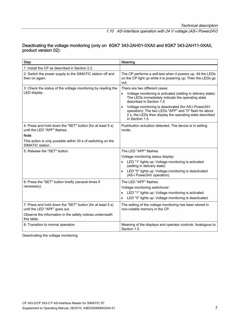
Technical description 1.10 AS-Interface operation with 24 V voltage (AS-i Power24V)
CP 343-2/CP 343-2 P AS-Interface Master for SIMATIC S7 Supplement to Operating Manual, 08/2010, A5E03006584020A-01 7
Deactivating the voltage monitoring (only on 6GK7 343-2AH01-0XA0 and 6GK7 343-2AH11-0XA0, product version 02): Step Meaning 1: Install the CP as described in Section 2.2. 2: Switch the power supply to the SIMATIC station off and then on again.
The CP performs a self-test when it powers up. All the LEDs on the CP light up while it is powering up. Then the LEDs go out.
3: Check the status of the voltage monitoring by reading the LED display.
There are two different cases: Voltage monitoring is activated (setting in delivery state):
The LEDs immediately indicate the operating state described in Section 1.5
Voltage monitoring is deactivated (for AS-i Power24V operation): The two LEDs "APF" and "0" flash for about 2 s, the LEDs then display the operating state described in Section 1.5.
4: Press and hold down the "SET" button (for at least 5 s) until the LED "APF" flashes. Note: This action is only possible within 30 s of switching on the SIMATIC station.
Pushbutton actuation detected. The device is in setting mode.
5: Release the "SET" button. The LED "APF" flashes. Voltage monitoring status display: LED "1" lights up: Voltage monitoring is activated
(setting in delivery state) LED "0" lights up: Voltage monitoring is deactivated
(AS-i Power24V operation).
6: Press the "SET" button briefly (several times if necessary).
The LED "APF" flashes. Voltage monitoring switchover: LED "1" lights up: Voltage monitoring is activated LED "0" lights up: Voltage monitoring is deactivated.
7: Press and hold down the "SET" button (for at least 5 s) until the LED "APF" goes out. Observe the information in the safety notices underneath this table.
The setting of the voltage monitoring has been stored in non-volatile memory in the CP.
8: Transition to normal operation Meaning of the displays and operator controls: Analogous to Section 1.5.
Deactivating the voltage monitoring

Technical description 1.10 AS-Interface operation with 24 V voltage (AS-i Power24V)
CP 343-2/CP 343-2 P AS-Interface Master for SIMATIC S7 8 Supplement to Operating Manual, 08/2010, A5E03006584020A-01
NOTICE Note on step 2: Termination of power-up by pressing the "SET" button: While the CP is powering up, do not press the "SET" button, if you press the "SET" button the CP will switch to a special internal state: An LED running light display is activated (LED "SF" - "PWR" - "APF" - "CER" - "AUP" - "CM"). The CP cannot operate normally in this special state. To cancel this special state, the power supply to the SIMATIC station must be switched off.
NOTICE Note on step 7 (storing the setting): If you want to cancel the setting of the voltage monitoring without saving it, you must switch off the power supply to the SIMATIC station instead of performing step 7.
The CP will be ready to run (normal operation) immediately after powering up.
NOTICE Note on steps 4 to 8: Perform steps 4 to 8 only if you want to change the current setting of the voltage monitoring.

CP 343-2/CP 343-2 P AS-Interface Master for SIMATIC S7 Supplement to Operating Manual, 08/2010, A5E03006584020A-01 9
Using the command interface 55.1 Description of FC "ASI_3422" (supplements)
CAUTION If the receive buffer of the FC ASI_3422 is too short, any bordering memory areas are overwritten. The length specification in the ANY pointer of the parameter RECV when calling the FC ASI_3422 is irrelevant. The required length of the receive buffer can be found in the description of the command. The supplements listed below must be observed.

Using the command interface 5.2 Description of the AS-i-slave commands (supplements)
CP 343-2/CP 343-2 P AS-Interface Master for SIMATIC S7 10 Supplement to Operating Manual, 08/2010, A5E03006584020A-01
5.2 Description of the AS-i-slave commands (supplements)
5.2.17 Read_extended_total_configuration (command number: 39H)
Supplement: The receive buffer must have a length of 221 bytes (byte 0 to 220). The highest bytes 172 to 220 are reserved and may be overwritten by the AS-i master with zero values.
5.2.21 Read_write_CTT2_request (command number: 44H)
Supplement: The receive buffer must have a length of 221 bytes (byte 0 to 220). The number of bytes actually transferred by the AS-i slave depends on the CTT2 response. The additional bytes contained in the receive buffer may be overwritten by the AS-i master with zero values.
5.2.30 Read_AS−i−slave_parameter_string (command number: 41H)
Supplement: The receive buffer must have a length of 221 bytes (byte 0 to 220). The number of bytes actually transferred by the AS-i slave depends on the slave. The additional bytes contained in the receive buffer may be overwritten by the AS-i master with zero values.
5.2.31 Read_AS−i−slave_ID−string (command number: 42H)
Supplement: The receive buffer must have a length of 221 bytes (byte 0 to 220). The number of bytes actually transferred by the AS-i slave depends on the slave. The additional bytes contained in the receive buffer may be overwritten by the AS-i master with zero values.
5.2.32 Read_AS−i−slave_diagnostic_string (command number: 43H)
Supplement: The receive buffer must have a length of 221 bytes (byte 0 to 220). The number of bytes actually transferred by the AS-i slave depends on the slave. The additional bytes contained in the receive buffer may be overwritten by the AS-i master with zero values.

CP 343-2/CP 343-2 P AS-Interface Master for SIMATIC S7 Supplement to Operating Manual, 08/2010, A5E03006584020A-01 11
Dealing with problems / error displays 77.1 Replacing a defective AS-i slave / automatic address programming
7.1.1 Automatic address programming after failure of one or more AS-i slaves (CP with firmware version V3.1 or higher)
AS-i slave replacement with CP 343-2 (6GK7 343-2AH01-0XA0) and CP 343-2 P (6GK7 343-2AH11-0XA0), product version 02/firmware version V3.1 or higher The "Automatic address programming" function makes it particularly easy for you to replace defective AS-i slaves.
Note Automatic address programming: You can use the automatic address programming function only if the CP is operating in "protected mode" and one or more AS-i slaves have failed. If several AS-i slaves have failed, the defective slaves must be uniquely identified in the configuration by their slave profile (I/O configuration, ID code, ID2 code) and ID1 code. The automatic address programming function does not work if two identical slaves have failed. The automatic address programming function also supports slaves with the "CTT5" profile (multi-address slaves) and AS-i devices which contain multiple internal slave addresses. A precondition for support is that each internal slave is uniquely identified (I/O configuration, ID code, ID2 code, ID1 code).
Examples of devices with multiple internal slave addresses which support automatic address programming: ● K60 module with 8DI/2DO (3RK2400-1HQ00-0AA3) ● M200D motor starter AS-i standard (3RK1325- ...). If no address has yet been assigned to these devices (setting in delivery state), only one zero address is visible on the bus. The device automatically suppresses the other internal zero addresses.

Dealing with problems / error displays 7.1 Replacing a defective AS-i slave / automatic address programming
CP 343-2/CP 343-2 P AS-Interface Master for SIMATIC S7 12 Supplement to Operating Manual, 08/2010, A5E03006584020A-01
Note Exceptions Automatic address programming does not work on the following devices as the internal slaves all have identical identifiers (I/O configuration, ID code, ID2 code, ID1 code). K60 module with 8 DI (3RK1200-0DQ00-0AA3, 3RK2200-0DQ00-0AA3,
3RK2200-1DQ00-1AA3) K45 safety-oriented module with 4 F-DI (3RK1205-0CQ00-0AA3).
Detection of a defective AS-i slave An illuminated "AUP" LED signals the following (in "protected operation" only): 1. Slave failure: ● Exactly one slave has failed, or ● A device containing multiple different slaves has failed, or ● Multiple slaves or devices have failed, each of the failed slaves having a unique
configuration (identifier)
2. Automatic address programming by the CP 343-2 is possible. You can identify a failed AS-i slave by flashing of the LED assigned to the slave on the front plate. The corresponding LEDs flash to indicate failure of a device with more than one internal slave address.
Replacement of a defective AS-i slave ● Replace the defective AS-i slave by an identical AS-i slave with address "zero" (setting in
delivery state),or ● Replace the defective AS-I device (containing multiple internal slave addresses) by an
identical AS-i device with address "zero" on all internal slaves (setting in delivery state).
Note Replacement of a defective AS-i slave: Only one address "zero" may be configured on the bus at any one time. If you want to replace several slaves or devices, you must replace them one after the other (with AS-i master switched on).
For the new slave or device, the CP 343-2 programs the address or addresses of the original node which has been replaced. The LEDs "AUP" and "CER" go out once all slaves have been correctly replaced. The newly added slave is signaled by illumination of the relevant LED.

Dealing with problems / error displays 7.1 Replacing a defective AS-i slave / automatic address programming
CP 343-2/CP 343-2 P AS-Interface Master for SIMATIC S7 Supplement to Operating Manual, 08/2010, A5E03006584020A-01 13
7.1.2 Automatic address programming after failure of an AS-i slave (CP with firmware version V3.0 or lower)
AS-i slave replacement with ● CP 343-2 (6GK7 343-2AH01-0XA0) and CP 343-2 P (6GK7 343-2AH11-0XA0),
product version 01 / firmware version V3.0 or earlier, and ● CP 343-2 (6GK7 343-2AH00-0XA0) and CP 343-2 P (6GK7 343-2AH10-0XA0),
all product versions or firmware version V2.x
Replacement The "Automatic address programming" function makes it particularly easy for you to replace defective AS-i slaves.
Note Automatic address programming: You can use the automatic address programming function only if the CP 343-2 is operating in "protected mode" and only one AS-i slave has failed. Slaves with the "CTT5" profile (multi-address slaves) do not support automatic address programming.
Detection of a defective AS-i slave An illuminated "AUP" LED signals the following (in "protected operation" only): ● Exactly one slave has failed ● Automatic address programming by the CP 343-2 is possible. You can identify a failed AS-i slave by flashing of the LED assigned to the slave on the front plate. The corresponding LEDs flash to indicate failure of a device with more than one internal slave address.
Replacement of a defective AS-i slave Replace the defective AS-i slave by an identical AS-i slave with address "zero" (setting in delivery state). For this slave, the CP 343-2 programs the address of the original node which has been replaced. The LEDs "AUP" and "CER" go out once the slave has been correctly replaced. The CP 343-2 signals the newly added slave by illumination of the relevant LED in the slave display.

Dealing with problems / error displays 7.2 Error displays/remedying errors
CP 343-2/CP 343-2 P AS-Interface Master for SIMATIC S7 14 Supplement to Operating Manual, 08/2010, A5E03006584020A-01
7.2 Error displays/remedying errors
7.2.1 Error displays/remedying errors (incompatibilities) Below are listed possible fault indicators, and potential remedial measures, when operating the CP 343−2 with incompatible slaves.
Error Possible cause Remedy CER indicator flickers or lights up, and other LEDs may also flicker or light up (AUP, SF, LEDs 0-9)
A connected slave is not compatible with the AS-i master since the slave operates in accordance with a higher version of the AS-i specification. For examples, see below.
Connect only slaves that are compatible with the AS-i specification of the master, or replace the (older) master with a current AS-i master that is compatible with the connected slaves. A master can process slaves if the version of the slave specification is equal to or lower than the version of the master specification.
Examples of incompatible combinations of AS-i slaves and AS-i master (list not complete): ● Slave of type A/B
including A/B slave with 4 inputs/3 outputs (e.g. 3RK2400-1FQ03-0AA3, in accordance with AS-i spec. V2.1) on master 6GK7342-2AH00-0XA0 (in accordance with AS-i spec. V2.0), especially if the highest output bit of the slave is set in the PLC (output D3 = "1").
● Slave of type A/B (spec. 3.0), including A/B slave with 4 inputs/4 outputs (e.g. 3RK2400-1DQ00-0AA3, in accordance with AS-i spec. V3.0) or A/B slave with 4 outputs (e.g. 3RK2100-1CT30-0AA3, in accordance with AS-i spec. V3.0) or A/B slave with analog profile 7.A.9 (e.g. 3RK2207-1BQ50-0AA3, in accordance with AS-i spec. V3.0) on master 6GK7343-2AH00-0XA0 (AS-i spec. V2.1) or master 6GK7343-2AH10-0XA0 (AS-i spec. V2.1)
● Slaves of the Combined Transaction Type 2-5 (CTT slaves in accordance with AS-i spec. 3.0), including A/B slave with profile 7.A.5 (e.g. 3RK1325-… SIRIUS motor starter M200D AS-i standard with 2 integral AS-i slaves) on master 6GK7343-2AH00-0XA0 (AS-i spec. V2.1) or master 6GK7343-2AH10-0XA0 (AS-i spec. V2.1)