Embed Size (px)
Citation preview

7/29/2019 CP R71 IPS-1Sensor AdminGuide
http://slidepdf.com/reader/full/cp-r71-ips-1sensor-adminguide 1/15
11 April, 2010
Administration Guide
IPS-1 Sensor
R71

7/29/2019 CP R71 IPS-1Sensor AdminGuide
http://slidepdf.com/reader/full/cp-r71-ips-1sensor-adminguide 2/15
More Information
The latest version of this document is at:http://supportcontent.checkpoint.com/documentation_download?ID=10505
For additional technical information about Check Point visit Check Point Support Center (http://supportcenter.checkpoint.com).
Feedback
Check Point is engaged in a continuous effort to improve its documentation. Please help us by sending your comments to us (mailto:[email protected]?subject=Feedback on IPS-1 Sensor R71 Administration Guide).
© 2010 Check Point Software Technologies Ltd.
All rights reserved. This product and related documentation are protected by copyright and distributed under licensing restricting their use, copying, distribution, and decompilation. No part of this product or relateddocumentation may be reproduced in any form or by any means without prior written authorization of CheckPoint. While every precaution has been taken in the preparation of this book, Check Point assumes noresponsibility for errors or omissions. This publication and features described herein are subject to changewithout notice.
RESTRICTED RIGHTS LEGEND:
Use, duplication, or disclosure by the government is subject to restrictions as set forth in subparagraph(c)(1)(ii) of the Rights in Technical Data and Computer Software clause at DFARS 252.227-7013 and FAR52.227-19.
TRADEMARKS:
Please refer to our Copyright page (http://www.checkpoint.com/copyright.html) for a list of our trademarks.
Please refer to our Third Party copyright notices (http://www.checkpoint.com/3rd_party_copyright.html) for alist of relevant copyrights.

7/29/2019 CP R71 IPS-1Sensor AdminGuide
http://slidepdf.com/reader/full/cp-r71-ips-1sensor-adminguide 3/15
Contents
Overview of IPS-1 ..................................................................................................... 4 IPS-1 Key Benefits ................................................................................................. 4
Unified Security Management ........................................................................... 4 Trusted Intrusion Prevention ............................................................................. 4 IPS Simplified .................................................................................................... 4 Dynamic Shielding ............................................................................................. 5
IPS-1 System Architecture ..................................................................................... 5 IPS-1 Sensor Deployment ...................................................................................... 5
Inline Intrusion Prevention ................................................................................. 5 Passive Intrusion Detection ............................................................................... 6
Managing IPS Profiles and Protections .................................................................. 6 Managing the IPS-1 Sensors ................................................................................... 7
Connecting to the IPS-1 Sensor ............................................................................. 7 IPS-1 Sensor Modes .............................................................................................. 7
Changing the Sensor Mode (Software) ............................................................. 8 Changing the Sensor Mode (Hardware) ............................................................ 8
IPS-1 Sensor Configuration ................................................................................... 9 Rebooting the IPS-1 Sensor .................................................................................. 9
IPS-1 Sensor Appliances ....................................................................................... 11 IPS-1 Sensor Appliance Models........................................................................... 11
IPS-1 Sensor 50C ............................................................................................ 11 IPS-1 Sensor 500C .......................................................................................... 11 IPS-1 Sensor 500F .......................................................................................... 12 IPS-1 Sensor 1000C ........................................................................................ 12 IPS-1 Sensor 1000F ........................................................................................ 12
Preparing the Sensor's Environment .................................................................... 12
Setting Up Sensor Appliance Network Connections ....................................... 13 Index ........................................................................................................................ 15
7/29/2019 CP R71 IPS-1Sensor AdminGuide
http://slidepdf.com/reader/full/cp-r71-ips-1sensor-adminguide 4/15

7/29/2019 CP R71 IPS-1Sensor AdminGuide
http://slidepdf.com/reader/full/cp-r71-ips-1sensor-adminguide 5/15
IPS-1 System Architecture
Overview of IPS-1 Page 5
Minimal-impact design
Centralized, scalable management
Customizable desktop GUI with real-time information and management
Dynamic Shielding
Presents network intelligence including OS and application information, CVE vulnerabilities, and impactand remediation details.
Determines anomalous behavior, reduces false positives and recognizes and dynamically shieldsvulnerable hosts against inevitable attacks.
IPS-1 System Architecture An IPS-1 deployment includes the following components:
IPS-1 Sensor : A device that is used exclusively for detecting and preventing network attacks, and sendsalerts to the Security Management Server. The sensor enforces "dedicated" IPS protections.
Security Management Server : The central management server which contains the object databaseand security policies. Security policies and IPS profiles are configured on the Security ManagementServer and installed on the IPS-1 sensors.
Log Server : Receives alert information from the Security Management Server. The Log server can beinstalled with the Security Management server or as a separate server.
SmartConsole: Windows-based remote graphical user interface (GUI) to the Security Managementserver for managing IPS-1 sensors, IPS profiles and IPS protections. The SmartConsole includes anumber of independent interlinked clients, primarily:
SmartDashboard for configuring protections and managing the entire IPS-1 system.
SmartView Tracker for viewing, tracking, and analyzing alerts.
IPS-1 Sensor DeploymentIPS-1 Sensors should be deployed at natural choke points according to network topology. Usually, sensorsshould be just within the network firewall. We do not recommend placing sensors outside the firewallbecause the sensor will not protected by the firewall and unfiltered traffic will place a heavy load on thesensor.
Ideally, network cores should also be protected with sensors. In some cases, such as in a complexswitching environment in a network core, sensors need to be used for intrusion detection in passive mode.
Sensors' monitoring interfaces are layer-3 transparent and do not have IP addresses. Each sensor has amanagement interface that requires an IP address that is routable to and from the Security ManagementServer. For enhanced security, we recommend that the management server be on a separate, out-of-bandnetwork.
Inline Intrusion PreventionFor intrusion prevention, sensors should be connected inline, so that all of the traffic to be monitored flowsthrough the IPS-1 Sensor. In this configuration, sensors can drop traffic containing attacks, according todefined and configurable confidence indexing.
Inline sensors' behavior upon failure can be configured to either open, passing through all traffic; or closed,
severing the traffic path.Inline sensors can be set to Detect-Only, to avoid the possibility dropping false-positive traffic . This way youcan track what the sensor would have done in prevention mode. You can fine-tune your prevention settingsin Detect-only/Monitor-only mode, and later change to prevention mode.

7/29/2019 CP R71 IPS-1Sensor AdminGuide
http://slidepdf.com/reader/full/cp-r71-ips-1sensor-adminguide 6/15

7/29/2019 CP R71 IPS-1Sensor AdminGuide
http://slidepdf.com/reader/full/cp-r71-ips-1sensor-adminguide 7/15
7/29/2019 CP R71 IPS-1Sensor AdminGuide
http://slidepdf.com/reader/full/cp-r71-ips-1sensor-adminguide 8/15
IPS-1 Sensor Modes
Managing the IPS-1 Sensors Page 8
IPS - Inline, fail-open: Inline intrusion prevention. Packets are processed for attack detection and areforwarded to the network only in accordance with protection settings. In fault conditions, all packets areallowed.
IPS - Inline, fail-closed: Inline intrusion prevention. Packets are processed for attack detection and areforwarded to the network only in accordance with protection settings. In fault conditions, all packets aredropped.
Warning - Changing the Working Mode may stop the flow of network traffic. Make surethat your network topology is correct for the IPS-1 Sensor Working Mode that youchoose.
Fault conditions are:
The Sensor has not completing booting and initializing
The Sensor loses power, or other hardware failure (dependent on hardware bypass NIC)
When the Sensor has crashed (dependent on hardware bypass NIC)
When an interface pair is in bypass mode, as a result of a failure, the bypass interfaces in most Sensor models will act as a crossover connection between the two systems on either side of the sensor. The four front-left copper interfaces on the new 200C/F and new 500C/F will act as a straight-though connection
when in bypass mode. All other hardware bypass pairs act as crossover connections when they are inbypass mode
Changing the Sensor Mode (Software)The IPS-1 Sensor mode is set during sensor installation.
To change the sensor mode from the command line:
1. Run: cpconfig
2. Enter 3 to change the IPS-1 Sensor Configuration.
3. Select Network Settings.
4. Select Set operating mode.5. Press Enter to select the Operating Mode and set one of the modes.
6. If you set the sensor to an IPS mode, set the interfaces to for the inline pairs. On certain appliances theinline pairs are already defined and cannot be changed.
7. Select Save.
8. Select Return to main menu.
9. Select Quit.
10. Enter 4 to exit the configuration menu.
11. Run: reboot
To change the sensor mode from the SmartDashboard:
1. Open the properties of the IPS-1 Sensor.
2. In the General page, set one of the Working Modes.
3. Install the policy on the IPS-1 Sensor for the changes to take effect.
Note - If policy installation fails when the IPS-1 Sensor is set to an IPS-InlineWorking Mode, log into the sensor's CLI and check that the interfaces are set towork as inline pairs.
Changing the Sensor Mode (Hardware)
The IPS-1 Sensor 50 models is ordered and delivered as SKU "P" for "IPS Monitor-Only" and "IPS (inlinefail-open)" modes, or SKU "D" for "IPS (inline, fail-closed)" and "IDS (passive)" modes. Switching betweenthe two configurations requires two steps in addition to changing the sensor's operating mode in software:an internal hardware setting change and a BIOS change.
7/29/2019 CP R71 IPS-1Sensor AdminGuide
http://slidepdf.com/reader/full/cp-r71-ips-1sensor-adminguide 9/15

7/29/2019 CP R71 IPS-1Sensor AdminGuide
http://slidepdf.com/reader/full/cp-r71-ips-1sensor-adminguide 10/15

7/29/2019 CP R71 IPS-1Sensor AdminGuide
http://slidepdf.com/reader/full/cp-r71-ips-1sensor-adminguide 11/15
Page 11
Chapter 3
IPS-1 Sensor AppliancesThis chapter discusses setting up Check Point pre-installed appliances. For open servers, see the R71Installation and Upgrade Guide (http://supportcontent.checkpoint.com/documentation_download?ID=10327 ).
For considerations for sensor location and network topology, see IPS-1 Sensor Deployment (on page 5).
In This Chapter
IPS-1 Sensor Appliance Models 11
Preparing the Sensor's Environment 12
IPS-1 Sensor Appliance Models
IPS-1 Sensor 50CFigure 3-1 IPS-1 Sensor 50C from front
Front — Two 10/100Mbps copper Ethernet front-panel interfaces used in IPS (inline) mode as an IPSpair with bypass support, or in IDS (passive) mode as two monitoring interfaces
Two 10/100/1000Mbps copper Ethernet front-panel interfaces, of which one is the managementinterface and the other can be used in IDS (passive) mode as an additional monitoring interface
IPS-1 Sensor 500CFigure 3-2 IPS-1 Sensor500C from front
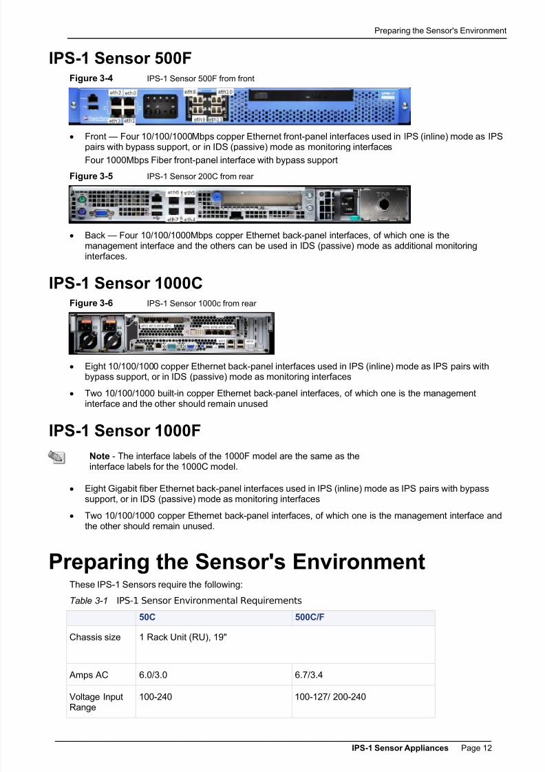
Front — Eight 10/100/1000Mbps copper Ethernet front-panel interfaces used in IPS (inline) mode as IPSpairs with bypass support, or in IDS (passive) mode as monitoring interfaces
Figure 3-3 IPS-1 Sensor 200C from rear
Back — Four 10/100/1000Mbps copper Ethernet back-panel interfaces, of which one is themanagement interface and the others can be used in IDS (passive) mode as additional monitoringinterfaces
7/29/2019 CP R71 IPS-1Sensor AdminGuide
http://slidepdf.com/reader/full/cp-r71-ips-1sensor-adminguide 12/15

7/29/2019 CP R71 IPS-1Sensor AdminGuide
http://slidepdf.com/reader/full/cp-r71-ips-1sensor-adminguide 13/15
Preparing the Sensor's Environment
IPS-1 Sensor Appliances Page 13
50C 500C/F
OperatingTemperature
0°C to +40°C +10°C to +35°C
Non-OperatingTemperature
-20°C to +80°C -40°C to +70°C
Non-OperatingRelativeHumidity
10-90%, non- condensing @ 35°C 90%, non- condensing @35°C
Emissions FCC Class A Device
Setting Up Sensor Appliance Network ConnectionsConnect the management interface to the management network. On the 50C, the management interface is
on the front panel. On other models, it should be one of the two built-in interfaces on the rear panel.For working in IDS (passive), any or all of the remaining interfaces can be used as monitoring ports.
For working in inline IPS mode, the inline pairs must conform to hardware configuration:
For the 50C, the inline pair is marked on the front panel.
For the 500 models, inline pairs are in vertical groupings.

7/29/2019 CP R71 IPS-1Sensor AdminGuide
http://slidepdf.com/reader/full/cp-r71-ips-1sensor-adminguide 14/15

7/29/2019 CP R71 IPS-1Sensor AdminGuide
http://slidepdf.com/reader/full/cp-r71-ips-1sensor-adminguide 15/15